EP4369391A1 - Dispositif de refroidissement - Google Patents
Dispositif de refroidissement Download PDFInfo
- Publication number
- EP4369391A1 EP4369391A1 EP23202535.3A EP23202535A EP4369391A1 EP 4369391 A1 EP4369391 A1 EP 4369391A1 EP 23202535 A EP23202535 A EP 23202535A EP 4369391 A1 EP4369391 A1 EP 4369391A1
- Authority
- EP
- European Patent Office
- Prior art keywords
- cooling
- component
- base
- fluid line
- section
- Prior art date
- Legal status (The legal status is an assumption and is not a legal conclusion. Google has not performed a legal analysis and makes no representation as to the accuracy of the status listed.)
- Pending
Links
Images






Classifications
-
- H—ELECTRICITY
- H05—ELECTRIC TECHNIQUES NOT OTHERWISE PROVIDED FOR
- H05K—PRINTED CIRCUITS; CASINGS OR CONSTRUCTIONAL DETAILS OF ELECTRIC APPARATUS; MANUFACTURE OF ASSEMBLAGES OF ELECTRICAL COMPONENTS
- H05K7/00—Constructional details common to different types of electric apparatus
- H05K7/20—Modifications to facilitate cooling, ventilating, or heating
- H05K7/2039—Modifications to facilitate cooling, ventilating, or heating characterised by the heat transfer by conduction from the heat generating element to a dissipating body
-
- H—ELECTRICITY
- H10—SEMICONDUCTOR DEVICES; ELECTRIC SOLID-STATE DEVICES NOT OTHERWISE PROVIDED FOR
- H10W—GENERIC PACKAGES, INTERCONNECTIONS, CONNECTORS OR OTHER CONSTRUCTIONAL DETAILS OF DEVICES COVERED BY CLASS H10
- H10W40/00—Arrangements for thermal protection or thermal control
- H10W40/40—Arrangements for thermal protection or thermal control involving heat exchange by flowing fluids
- H10W40/47—Arrangements for thermal protection or thermal control involving heat exchange by flowing fluids by flowing liquids, e.g. forced water cooling
-
- H—ELECTRICITY
- H05—ELECTRIC TECHNIQUES NOT OTHERWISE PROVIDED FOR
- H05K—PRINTED CIRCUITS; CASINGS OR CONSTRUCTIONAL DETAILS OF ELECTRIC APPARATUS; MANUFACTURE OF ASSEMBLAGES OF ELECTRICAL COMPONENTS
- H05K7/00—Constructional details common to different types of electric apparatus
- H05K7/20—Modifications to facilitate cooling, ventilating, or heating
- H05K7/20218—Modifications to facilitate cooling, ventilating, or heating using a liquid coolant without phase change in electronic enclosures
- H05K7/20272—Accessories for moving fluid, for expanding fluid, for connecting fluid conduits, for distributing fluid, for removing gas or for preventing leakage, e.g. pumps, tanks or manifolds
-
- H—ELECTRICITY
- H10—SEMICONDUCTOR DEVICES; ELECTRIC SOLID-STATE DEVICES NOT OTHERWISE PROVIDED FOR
- H10W—GENERIC PACKAGES, INTERCONNECTIONS, CONNECTORS OR OTHER CONSTRUCTIONAL DETAILS OF DEVICES COVERED BY CLASS H10
- H10W40/00—Arrangements for thermal protection or thermal control
- H10W40/20—Arrangements for cooling
- H10W40/22—Arrangements for cooling characterised by their shape, e.g. having conical or cylindrical projections
-
- H—ELECTRICITY
- H10—SEMICONDUCTOR DEVICES; ELECTRIC SOLID-STATE DEVICES NOT OTHERWISE PROVIDED FOR
- H10W—GENERIC PACKAGES, INTERCONNECTIONS, CONNECTORS OR OTHER CONSTRUCTIONAL DETAILS OF DEVICES COVERED BY CLASS H10
- H10W40/00—Arrangements for thermal protection or thermal control
- H10W40/70—Fillings or auxiliary members in containers or in encapsulations for thermal protection or control
- H10W40/77—Auxiliary members characterised by their shape
- H10W40/774—Pistons, e.g. spring-loaded members
-
- H—ELECTRICITY
- H10—SEMICONDUCTOR DEVICES; ELECTRIC SOLID-STATE DEVICES NOT OTHERWISE PROVIDED FOR
- H10W—GENERIC PACKAGES, INTERCONNECTIONS, CONNECTORS OR OTHER CONSTRUCTIONAL DETAILS OF DEVICES COVERED BY CLASS H10
- H10W40/00—Arrangements for thermal protection or thermal control
- H10W40/20—Arrangements for cooling
- H10W40/22—Arrangements for cooling characterised by their shape, e.g. having conical or cylindrical projections
- H10W40/226—Arrangements for cooling characterised by their shape, e.g. having conical or cylindrical projections characterised by projecting parts, e.g. fins to increase surface area
Definitions
- the present invention relates to a cooling device for dissipating heat from an object to be cooled, such as an electronic component arranged in particular on a circuit board, for example a processor chip, with a cooling fluid line for the flow of cooling fluid, with a base component which has one or more cooling fluid line sections of the cooling fluid line, and with a heat sink which can be arranged on an object to be cooled and which consists in particular of solid material, preferably in the form of a plate, for absorbing waste heat from the object to be cooled and for forwarding the waste heat to cooling fluid flowing through the cooling fluid line of the cooling device during operation of the cooling device, in particular such a heat sink made of metal or a heat-conducting metal alloy.
- Cooling devices for dissipating heat from objects to be cooled are also known as heat exchangers and are used in many areas of technology. Such cooling devices are particularly important for cooling battery or accumulator systems for electric vehicles, but also power electronics components, busbars or processor chips.
- the cooling device mentioned at the beginning is usually part of a cooling system including a pump and other components, whereby the system ensures that cooling medium, such as water or the like, is continuously fed through the cooling device.
- the actual cooling body which is usually attached to the object to be cooled, is often part of the base component, which has cooling fluid line sections of the cooling fluid line of the cooling device for the inlet and outlet of the cooling medium. It can, for example, form the one-piece flat underside of the base component of the cooling device and can be placed with this on the front sides of several adjacent objects to be cooled.
- This type of cooling device is disadvantageous, among other things, when several adjacent objects are to be cooled at the same time, the front sides of which should theoretically be in the same plane, but have slight differences in height due to manufacturing tolerances, for example. These tolerances can be compensated to a certain extent with intermediate layers of thermal paste. However, depending on the thickness, this thermal paste impairs the heat dissipation from the objects to be cooled. This can be critical for particularly heat-sensitive components or for components that generate a lot of heat, such as high-performance chips, so only very thin layers of thermal paste are permitted. However, the manufacturing tolerances often exceed this permissible layer thickness.
- the object of the present invention is therefore to further develop the cooling devices mentioned at the beginning.
- larger manufacturing tolerances should also be able to be compensated.
- a cooling device is accordingly characterized in that the cooling body is arranged on a cooling component of the cooling device having a cooling fluid line section of the cooling fluid line of the cooling device, which cooling component is movably connected to the base component with a fluid-conducting connection of this cooling fluid line section to a cooling fluid line section of the base component, so that the cooling component and the base component can be moved either towards or away from each other relative to one another as required in order to adjust the position of the cooling body of the cooling component.
- the heat sink is no longer part of the basic component of the cooling device, but is attached to a separate cooling component arranged or possibly part of the same, which in turn is movably connected to the base component.
- the relative position of the cooling body of the cooling component could thus still be changed, for example, even after the base component of the cooling device has already been arranged in a fixed location (before or even during operation of the same).
- the base component prefferably immovable heat sink and for the cooling device to be initially positioned in use in such a way that this further heat sink is arranged on a first object to be cooled or - if necessary with the help of a thermal paste - on its contact surface to be cooled.
- the heat sink of the cooling component movably connected to the base component could then, due to its mobility relative to the base component, be arranged on another object to be cooled, which is, for example, roughly in the same plane as the first object to be cooled, but whose surface to be cooled or its contact surface may deviate slightly in height from the contact surface of the first object to be cooled, for example due to manufacturing tolerances.
- the heat sink of the cooling component movably connected to the base component is concerned, it is preferably plate-shaped and/or has cooling fins.
- the cooling fluid line section of the base component (which is arranged in particular in a stationary manner on the base component) and the cooling fluid line section of the cooling component movably connected to the base component (which is arranged in particular in a stationary manner on the cooling component) each have a preferably terminal, in particular hollow-cylindrical hollow body (partial) section.
- the two hollow body (partial) sections are connected to one another in a fluid-conducting manner, in particular in a sliding, axially movable manner.
- one hollow body section in particular the hollow body section of the cooling component, is inserted or pushed in a precise, coaxial manner into the interior of the other hollow body section, in particular the hollow body section of the base component.
- one sealing ring can be used to seal the two hollow body sections that can move relative to one another.
- the cooling fluid could, for example, be supplied to the cooling component or the cooling fluid line section thereof via the aforementioned hollow body sections.
- the cooling fluid is expediently discharged from the cooling component again once it has absorbed the waste heat from the object to be cooled via the cooling body, preferably back to the base component or back into another/different cooling fluid line section of the base component. Accordingly, the cooling fluid would first flow into the (first) cooling fluid line section of the base component, then pass into the cooling fluid line section of the cooling component and then into the other cooling fluid line section of the base component.
- the cooling fluid line section of the cooling component movably connected to the base component has a second, preferably terminal, in particular hollow-cylindrical hollow body (partial) section, that a further or second cooling fluid line section of the base component has a preferably terminal, in particular hollow-cylindrical hollow body (partial) section, and that for the movable connection of the base component and cooling component, these two hollow body (partial) sections are also connected to one another, in particular in a sliding, axially movable and fluid-conducting manner.
- the one hollow body section, in particular the second hollow body section of the cooling component being inserted coaxially in a precise fit into the interior of the other hollow body section, in particular the hollow body section of the further cooling fluid line of the base component, preferably also using at least one sealing ring that seals the two hollow body sections against one another in a fluid-tight manner.
- the heat sink of the cooling component can extend along a plane that runs at an angle, in particular perpendicular to the two opposite directions of movement, in which the cooling component and the base component can be moved towards or away from each other as required.
- An inner side of the heat sink which extends in particular in a transverse axial plane (transverse axial with regard to the axial relative movement between the respective hollow body sections), can also form one of the inner wall surfaces of the cooling fluid line section of the cooling component that delimits the cooling medium. Accordingly, the cooling medium would/could flow directly past the heat sink on the inside during operation of the cooling device and absorb the waste heat of the object to be cooled.
- the inner wall surfaces of the cooling fluid line section of the cooling component opposite the inside of the cooling body can form force compensation surfaces, so that fluid pressure forces acting on the inside of the cooling body, in particular axial ones (axial with respect to the axial relative movement between the respective hollow body sections) caused by the pressure of a cooling fluid flowing through the cooling component, are canceled out by corresponding oppositely directed fluid pressure forces acting on these force compensation surfaces, in particular axial ones.
- One of the force compensation surfaces can expediently be formed by an inner wall surface of the or each hollow body section of the cooling component, which extends in particular transversely axially and which delimits a terminal, in particular transversely axially extending, connection channel of this hollow body section, via which cooling fluid can flow from the cooling fluid section of the base body to the cooling fluid section of the cooling component (or vice versa).
- the cooling component movably connected to the base component can also be operatively connected to the base component by means of a pre-tensionable clamping element of the cooling device, preferably supported on the one hand on the base component and on the other hand on the cooling component, preferably by means of a spring.
- a pre-tensionable clamping element of the cooling device preferably supported on the one hand on the base component and on the other hand on the cooling component, preferably by means of a spring.
- the pre-tensioning of can be brought about by a relative movement between the cooling component and the base component, which moves the cooling component and the base component towards one another or would move it towards one another.
- the clamping element can exert forces on the cooling component and the base component that move or would move the cooling component and the base component away from each other, so that - if desired - contact or pressing forces can be exerted on the contact surface of the object to be cooled, so that stable heat transfer between the heat sink and the contact surface is guaranteed during operation.
- the base component can furthermore have a first base body made in particular of injection-molded plastic, which is connected in a fluid-tight manner, in particular by forming one or more cooling fluid line sections, to a second base body of the base component, in particular deep-drawn, preferably solid, in particular made of metal or a heat-conducting metal alloy.
- One or each hollow body section of the cooling fluid line section of the base component can preferably be formed by the first base body made of plastic.
- one or each hollow body section of the cooling fluid line section of the base component can extend from a first (in particular large-area) side of the second base body of the base component through a (possibly respective) through hole in this second base body, end on or beyond one or the side of the second base body opposite the first side (in particular large-area) and in particular be axially movably connected there to one or each hollow body section of the cooling fluid line section of the cooling component movably connected to the base component.
- the second base body of the base component can also form, at least in some areas, a further cooling body for absorbing waste heat from objects to be cooled and for passing on the waste heat to cooling fluid flowing through the cooling fluid line of the cooling device during operation of the cooling device.
- a further cooling body for absorbing waste heat from objects to be cooled and for passing on the waste heat to cooling fluid flowing through the cooling fluid line of the cooling device during operation of the cooling device.
- the second base body has at least one cooling region, the inside of which, which is opposite an outside that can be arranged on an object to be cooled (in particular directly without lateral offset), forms an inner wall surface of a cooling fluid line section of the base component.
- the cooling component movably connected to the base component can furthermore have a base body made of plastic, in particular an injection-molded one, which together with the cooling body, to the inside of which this base body of the cooling component is fluid-tightly connected, forms a partial section of the cooling fluid line section of the cooling component.
- the base body made of plastic can also simultaneously form or shape the or each hollow body section of the cooling fluid line section of the cooling component, or the hollow body section or sections can be shaped accordingly by the base body made of plastic.
- the above-mentioned partial section of the cooling fluid line section of the cooling component which is formed by the plastic base body of the cooling component and the heat sink of the cooling component and runs in particular transversely axially, can further connect the two hollow body sections of the cooling fluid line section of the cooling component to one another in a fluid-conducting manner.
- this is preferably a material and/or positive connection.
- This material and/or form-fitting connection can involve nano- and/or microstructures, preferably produced by physical and/or chemical processes, which are introduced into the surface of the connection area of the second base body of the base component or into the surface of the connection area of the cooling body of the cooling component.
- nano- and/or microstructures which cause an increase in the surface in the connection area and/or have depressions comprising undercuts and/or barbs.
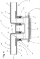
- a cooling device 10 which, according to the invention, has a base component 11 and a cooling component 12 which is movable relative to the base component.
- the cooling device 10 further comprises a cooling fluid line 13, via which cooling fluid, such as water, can be guided along a cooling body 14 of the cooling device 10 in order to dissipate waste heat absorbed by the cooling body 14 from an object 15 to be cooled, in the present case, for example, a high-performance computer chip.
- cooling fluid such as water
- the cooling device 10 is part of an otherwise known cooling system, which has, among other things, a cooling fluid source and a pump which conveys the cooling fluid through the cooling fluid line 13 of the cooling device 10 (in each case not shown).
- the cooling fluid line 13 of the cooling device 10 is composed of several sections.
- the base component 11 here has a cooling fluid line section 16 and a cooling fluid line section 17 of the cooling fluid line 13 and the cooling component 12 has a cooling fluid line section 18.
- the cooling fluid is supplied from the cooling fluid source to the cooling fluid line section 16 of the base component 11, then flows through the cooling fluid line section 18 of the cooling component 12, where it absorbs the waste heat of the heat sink 14 (which in this case is provided with a plurality of cooling fins 34) by flowing along an inner side 19 of the heat sink 14 forming an inner wall of the cooling fluid line section 18, and finally flows into the cooling fluid line section 17 of the base component 11, from which it is then returned to the cooling fluid source.
- the waste heat of the heat sink 14 which in this case is provided with a plurality of cooling fins 34
- Both the cooling fluid line section 16 and the cooling fluid line section 17 of the base component 11 each have a terminal hollow body section 16a or 17a, which each forms a first subsection of the respective cooling fluid line section 16 or 17.
- the end hollow body sections 16a and 17a of the cooling fluid line section 16 and 17 are components of a first base body 21 made of plastic, which also has line walls 22 and 23 connected in one piece to these hollow body sections 16a, 17a.
- the hollow body sections 16a and 17a of the respective cooling fluid line sections 16 and 17 of the base component 11 each extend from a first large-area side 25 of the second base body 24 of the base component 11 through a through hole 29 in this second base body 24 and end on or beyond the large-area second side 26 of the second base body 24 opposite the first side 25.
- the cooling fluid line section 18 of the cooling component 12 also has hollow body sections 18a and 18b, respectively, which form corresponding subsections of the cooling fluid line section 18 of the cooling component 12.
- the hollow body sections 16a and 18a are connected to each other in pairs on the one hand and the hollow body sections 17a and 18b on the other hand.
- connections are designed in such a way that (sliding) axial relative movements between the hollow body sections of the respective hollow body section pair 16a, 18a or 17a, 18b are possible (which, for example, a worker could initiate if necessary), so that as a result the base component 11 and the cooling component 12 can also be moved relative to one another.
- Each hollow body section 18a and 18b has, in a connection region in which the hollow body sections 16a, 18a and 17a, 18b are correspondingly slidably connected to one another, an outer diameter at the end which is slightly smaller than the inner diameter of the respectively associated hollow body section 16a or 17a of the cooling fluid line 16 or 17 of the base component 11, so that during the manufacture of the cooling device 10 each hollow body section 18a, 18b could be inserted coaxially into the interior of the respectively associated hollow body section 16a or 16b with a precise fit.
- the hollow body sections 16a and 18a or the hollow body sections 17a and 18b and thus also the cooling component 12 on the one hand and the base component 11 on the other hand can be moved relative to one another in the axial direction by a worker if necessary (overcoming frictional or holding forces), namely either towards or away from one another.
- a sealing ring 33 which is arranged on the outside of the hollow body section 18a or 18b and on the inside of the hollow body section 16a or 17a between the respective pairs of the associated hollow body sections 16a, 18a or 17a, 18b, fluid tightness is achieved or it is achieved that fluid cannot flow outwards in the respective connection area between the hollow body sections of each pair 16a, 18a or 17a, 18b.
- the possibilities of being able to move the cooling component 12 and the base component 11 axially towards each other if necessary are limited by a respective stop surface 20 or an end stop of the hollow body section 16a or 17a of the base component 11, against which the respective free end of the hollow body section 18a or 18b of the cooling component 12 strikes.
- the cooling component 12 which is movably connected to the base component 11, also has a base body 27, in particular injection-molded, made of plastic, which on the one hand forms the hollow body sections 18a, 18b of the cooling fluid line section 18 of the cooling component 12, which form the respective subsections of the cooling fluid line section 18, and which on the other hand, together with the cooling body 14, to the inner side 19 of which the base body 27 is fluid-tightly connected, forms a transversely axially extending subsection 18c of the cooling fluid line section 18, which connects the two hollow body sections 18a, 18b to one another in a fluid-conducting manner.
- a base body 27, in particular injection-molded, made of plastic which on the one hand forms the hollow body sections 18a, 18b of the cooling fluid line section 18 of the cooling component 12, which form the respective subsections of the cooling fluid line section 18, and which on the other hand, together with the cooling body 14, to the inner side 19 of which the base body 27 is fluid-tightly connected, forms a transversely axially extending subsection 18c of
- This section 18c which runs transversely axially or perpendicularly to the hollow body sections 18a, 18b, is formed by the base body 27 and the cooling body 14 of the cooling component 12 or by its inner side 19.
- this is a material and/or form-fitting connection.
- This involves nano- and/or microstructures produced by physical and/or chemical processes in the metal surface of the corresponding connection area of the second base body 24 made of metal of the base component 11. These are preferably nano- and/or microstructures that cause an enlargement of the metal surface in the connection area and/or have depressions comprising undercuts and/or barbs.
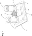
- FIG. 6-10 a further embodiment 28 of a cooling device according to the invention is shown. Identical or similar components are provided with the same reference numbers as in the cooling device 10, unless otherwise stated. The following - unless otherwise stated - will primarily focus on the differences between the cooling device 28 and the cooling device 10.
- a special feature of the cooling device 28 is that the cooling component 12 thereof has suitably arranged and designed force compensation surfaces 31, which ensure that the fluid pressure of the cooling fluid that flows through the cooling device 28 during operation does not trigger any resulting axial forces (i.e. forces in the direction of movement of the cooling component 12 or in the direction of the relative movement between the pairs of hollow body sections 16a, 18a or 17a, 18b) that could possibly damage the object 15 to be cooled.
- any axial forces of the cooling fluid acting on the cooling body 14 in the direction of the object 15 to be cooled are compensated in the cooling device 28 by corresponding axial counterforces acting in the opposite direction, which the cooling fluid simultaneously exerts on the force compensation surfaces 31.
- each hollow body section 18a, 18b extends from the second side 26 of the second base body 24 of the base component 11 (from below) through the respective through hole 29 and ends beyond or on the first side 25 of the second base body 24, namely forming a respective transversely axially extending Connection channel 30, which adjoins the cooling fluid line section 16b or 17b extending (coaxially thereto) on the first side 25 of the second base body 24 and whose transversely axially extending inner wall surface (a region thereof) forms one of the force compensation surfaces 31.
- the hollow body sections 16a, 17a, into which the hollow body sections 18a and 18b are inserted, also extend for the most part on the first side 26 of the second base body 24 of the base component 11.
- cooling component 12 is operatively connected to the base component 11 by means of a pre-tensionable tensioning element 32 of the cooling device, which is supported on the one hand on the base component 11 and on the other hand on the cooling component 12, in this case by means of a spring.
- Cooling device 25 first side second body 11 Basic component Basic component 12 Cooling component 26 second side base body 13 Cooling fluid line cooling device Basic component 14 Heatsink 27 Main body cooling component 15 object to be cooled 28 Cooling device 16 Cooling fluid line section 29 Through hole Basic component 30 Connection channel 16a Hollow body section 31 Force compensation surfaces 16b Cooling fluid line section 32 Clamping element 17 Cooling fluid line section 33 Sealing ring Basic component 34 Cooling fins 17a Hollow body section 17b Cooling fluid line section 18 Cooling fluid line section Cooling component 18a Hollow body section 18b Hollow body section 18c transverse axial Cooling fluid line section 19 Inside heatsink 20 Stop surface hollow body section 21 first basic body basic component 22 Pipe wall 23 Pipe wall 24 second basic body basic component
Landscapes
- Engineering & Computer Science (AREA)
- Microelectronics & Electronic Packaging (AREA)
- Physics & Mathematics (AREA)
- Thermal Sciences (AREA)
- Cooling Or The Like Of Semiconductors Or Solid State Devices (AREA)
- Cooling Or The Like Of Electrical Apparatus (AREA)
Applications Claiming Priority (1)
| Application Number | Priority Date | Filing Date | Title |
|---|---|---|---|
| DE102022126106.9A DE102022126106B4 (de) | 2022-10-10 | 2022-10-10 | Kühleinrichtung |
Publications (1)
| Publication Number | Publication Date |
|---|---|
| EP4369391A1 true EP4369391A1 (fr) | 2024-05-15 |
Family
ID=88297142
Family Applications (1)
| Application Number | Title | Priority Date | Filing Date |
|---|---|---|---|
| EP23202535.3A Pending EP4369391A1 (fr) | 2022-10-10 | 2023-10-09 | Dispositif de refroidissement |
Country Status (4)
| Country | Link |
|---|---|
| US (1) | US12543294B2 (fr) |
| EP (1) | EP4369391A1 (fr) |
| CN (1) | CN117878076A (fr) |
| DE (1) | DE102022126106B4 (fr) |
Families Citing this family (1)
| Publication number | Priority date | Publication date | Assignee | Title |
|---|---|---|---|---|
| DK182224B1 (en) * | 2024-11-12 | 2025-12-17 | Asetek Danmark As | Cooling structure with adjustable cold plate position |
Citations (2)
| Publication number | Priority date | Publication date | Assignee | Title |
|---|---|---|---|---|
| US4977444A (en) * | 1987-10-26 | 1990-12-11 | Hitachi, Ltd. | Semiconductor cooling apparatus |
| US20070091569A1 (en) * | 2005-10-25 | 2007-04-26 | International Business Machines Corporation | Cooling apparatus and method employing discrete cold plates disposed between a module enclosure and electronics components to be cooled |
Family Cites Families (7)
| Publication number | Priority date | Publication date | Assignee | Title |
|---|---|---|---|---|
| US4882654A (en) * | 1988-12-22 | 1989-11-21 | Microelectronics And Computer Technology Corporation | Method and apparatus for adjustably mounting a heat exchanger for an electronic component |
| JP2724033B2 (ja) * | 1990-07-11 | 1998-03-09 | 株式会社日立製作所 | 半導体モジユール |
| JP2792304B2 (ja) * | 1992-01-22 | 1998-09-03 | 日本電気株式会社 | 集積回路用冷却装置 |
| JP2745948B2 (ja) * | 1992-04-06 | 1998-04-28 | 日本電気株式会社 | 集積回路の冷却構造 |
| CA2102662C (fr) * | 1992-11-09 | 1997-10-07 | Shinya Akamatsu | Refroidissement de circuits integres |
| CN110662389B (zh) * | 2018-06-28 | 2021-01-01 | 华为技术有限公司 | 一种散热装置以及电子设备 |
| EP3895231A1 (fr) * | 2018-12-14 | 2021-10-20 | 3M Innovative Properties Company | Ensembles plaque froide de batterie de véhicule électrique |
-
2022
- 2022-10-10 DE DE102022126106.9A patent/DE102022126106B4/de active Active
-
2023
- 2023-10-09 EP EP23202535.3A patent/EP4369391A1/fr active Pending
- 2023-10-10 CN CN202311303487.6A patent/CN117878076A/zh active Pending
- 2023-10-10 US US18/378,448 patent/US12543294B2/en active Active
Patent Citations (2)
| Publication number | Priority date | Publication date | Assignee | Title |
|---|---|---|---|---|
| US4977444A (en) * | 1987-10-26 | 1990-12-11 | Hitachi, Ltd. | Semiconductor cooling apparatus |
| US20070091569A1 (en) * | 2005-10-25 | 2007-04-26 | International Business Machines Corporation | Cooling apparatus and method employing discrete cold plates disposed between a module enclosure and electronics components to be cooled |
Also Published As
| Publication number | Publication date |
|---|---|
| DE102022126106A1 (de) | 2024-04-11 |
| US20240121915A1 (en) | 2024-04-11 |
| DE102022126106B4 (de) | 2026-01-22 |
| CN117878076A (zh) | 2024-04-12 |
| US12543294B2 (en) | 2026-02-03 |
Similar Documents
| Publication | Publication Date | Title |
|---|---|---|
| DE60028660T3 (de) | Rohr sowie Verfahren und Vorrichtung zu seiner Herstellung | |
| DE10125636B4 (de) | Kühler für elektrische und/oder elektronische Bauteile | |
| EP3163242B1 (fr) | Indirekter ladeluftkühler | |
| CH685140A5 (de) | Kühleinrichtung für elektrische Bauelemente. | |
| DE112022004158T5 (de) | Halbleitervorrichtung | |
| EP4343260A2 (fr) | Dissipateur thermique à caloduc pour un fonctionnement pulsé et procédé de fabrication d'un tel dissipateur thermique à caloduc | |
| EP4386304A2 (fr) | Composant de refroidissement | |
| EP4369391A1 (fr) | Dispositif de refroidissement | |
| DE102018111585A1 (de) | Vorrichtung zur Wärmeübertragung sowie Verfahren zum Herstellen der Vorrichtung | |
| DE20121112U1 (de) | Sammelkasten für einen Wärmeaustauscher, insbesondere an Kraftfahrzeugen | |
| WO2023061758A1 (fr) | Ailette de refroidissement de refroidisseur, par lequel un fluide peut s'écouler, pour le refroidissement de l'électronique de puissance | |
| DE102018210141A1 (de) | Diodenlaseranordnung und Verfahren zur Herstellung einer Diodenlaseranordnung | |
| EP0952421A2 (fr) | Echangeur de chaleur à plusieurs passes | |
| EP4616447A1 (fr) | Structure de refroidissement d'un refroidisseur à travers lequel un fluide peut s'écouler | |
| EP3459110B1 (fr) | Unité de boîte de refroidissement et système électronique de puissance doté d'une unité de boîte de refroidissement | |
| DE102023210493A1 (de) | Heatpipekühlkörper | |
| EP3113220B1 (fr) | Dissipateur thermique | |
| DE102019114890B4 (de) | Kühlmechanismus zwischen einem Linearmotorläufer und seiner kombinierten Plattform | |
| DE2059122B2 (de) | Lötverbindung | |
| DE102022209786A1 (de) | Wärmetauscher zur Kühlung von Komponenten | |
| DE102012220435A1 (de) | Kühlplatte | |
| DE102007063641B4 (de) | Verbindungsanordnung für den Installationsbereich | |
| EP3364453B1 (fr) | Boîte de refroidissement, dispositif de refroidissement ainsi que procédé de fabrication d'une boîte de refroidissement | |
| DE102015105481A1 (de) | Profilverbinder | |
| DE102023115116A1 (de) | Kühlbauteil und Verfahren zur Herstellung desselben |
Legal Events
| Date | Code | Title | Description |
|---|---|---|---|
| PUAI | Public reference made under article 153(3) epc to a published international application that has entered the european phase |
Free format text: ORIGINAL CODE: 0009012 |
|
| STAA | Information on the status of an ep patent application or granted ep patent |
Free format text: STATUS: THE APPLICATION HAS BEEN PUBLISHED |
|
| AK | Designated contracting states |
Kind code of ref document: A1 Designated state(s): AL AT BE BG CH CY CZ DE DK EE ES FI FR GB GR HR HU IE IS IT LI LT LU LV MC ME MK MT NL NO PL PT RO RS SE SI SK SM TR |
|
| STAA | Information on the status of an ep patent application or granted ep patent |
Free format text: STATUS: REQUEST FOR EXAMINATION WAS MADE |
|
| 17P | Request for examination filed |
Effective date: 20241113 |
|
| RBV | Designated contracting states (corrected) |
Designated state(s): AL AT BE BG CH CY CZ DE DK EE ES FI FR GB GR HR HU IE IS IT LI LT LU LV MC ME MK MT NL NO PL PT RO RS SE SI SK SM TR |
|
| RAP3 | Party data changed (applicant data changed or rights of an application transferred) |
Owner name: ERWIN QUARDER SYSTEMTECHNIK GMBH |