EP4370200B1 - Système de tomographie par impédance permettant un retour d'alignement d'un dispositif de charge pour un dispositif médical implantable - Google Patents
Système de tomographie par impédance permettant un retour d'alignement d'un dispositif de charge pour un dispositif médical implantable Download PDFInfo
- Publication number
- EP4370200B1 EP4370200B1 EP22751317.3A EP22751317A EP4370200B1 EP 4370200 B1 EP4370200 B1 EP 4370200B1 EP 22751317 A EP22751317 A EP 22751317A EP 4370200 B1 EP4370200 B1 EP 4370200B1
- Authority
- EP
- European Patent Office
- Prior art keywords
- charging device
- medical system
- medical
- coil
- housing surface
- Prior art date
- Legal status (The legal status is an assumption and is not a legal conclusion. Google has not performed a legal analysis and makes no representation as to the accuracy of the status listed.)
- Active
Links
Images


Classifications
-
- A—HUMAN NECESSITIES
- A61—MEDICAL OR VETERINARY SCIENCE; HYGIENE
- A61N—ELECTROTHERAPY; MAGNETOTHERAPY; RADIATION THERAPY; ULTRASOUND THERAPY
- A61N1/00—Electrotherapy; Circuits therefor
- A61N1/18—Applying electric currents by contact electrodes
- A61N1/32—Applying electric currents by contact electrodes alternating or intermittent currents
- A61N1/36—Applying electric currents by contact electrodes alternating or intermittent currents for stimulation
- A61N1/372—Arrangements in connection with the implantation of stimulators
- A61N1/378—Electrical supply
- A61N1/3787—Electrical supply from an external energy source
-
- A—HUMAN NECESSITIES
- A61—MEDICAL OR VETERINARY SCIENCE; HYGIENE
- A61N—ELECTROTHERAPY; MAGNETOTHERAPY; RADIATION THERAPY; ULTRASOUND THERAPY
- A61N1/00—Electrotherapy; Circuits therefor
- A61N1/18—Applying electric currents by contact electrodes
- A61N1/32—Applying electric currents by contact electrodes alternating or intermittent currents
- A61N1/36—Applying electric currents by contact electrodes alternating or intermittent currents for stimulation
- A61N1/372—Arrangements in connection with the implantation of stimulators
- A61N1/37211—Means for communicating with stimulators
- A61N1/37217—Means for communicating with stimulators characterised by the communication link, e.g. acoustic or tactile
- A61N1/37223—Circuits for electromagnetic coupling
- A61N1/37229—Shape or location of the implanted or external antenna
-
- A—HUMAN NECESSITIES
- A61—MEDICAL OR VETERINARY SCIENCE; HYGIENE
- A61N—ELECTROTHERAPY; MAGNETOTHERAPY; RADIATION THERAPY; ULTRASOUND THERAPY
- A61N1/00—Electrotherapy; Circuits therefor
- A61N1/18—Applying electric currents by contact electrodes
- A61N1/32—Applying electric currents by contact electrodes alternating or intermittent currents
- A61N1/36—Applying electric currents by contact electrodes alternating or intermittent currents for stimulation
- A61N1/372—Arrangements in connection with the implantation of stimulators
- A61N1/37211—Means for communicating with stimulators
- A61N1/37252—Details of algorithms or data aspects of communication system, e.g. handshaking, transmitting specific data or segmenting data
- A61N1/37258—Alerting the patient
Definitions
- the present invention relates to a medical system comprising an implantable medical device and an external charging device for charging an energy storage device of the medical device, for example in the form of an implantable pulse generator (IPG).
- IPG implantable pulse generator
- One way to determine alignment is to identify the conductive metallic titanium housings typically used in implants (pacemakers, neurostimulators).
- arrays of magnetic field sensor coils are known to be located on the coil of the charging device.
- the magnetic field sensor coils change amplitude.
- a detection of the primary coil of the charging device metal detector mode
- the presence of a backscatter e.g. LSK
- US 2018/0212451 A1 discloses charging an energy source located in an implantable medical device implanted in a patient, the charging device comprising first and second pairs of electric coils configured to generate first and second uniform magnetic fields in overlapping first and second cylindrical regions located between the respective pairs of electric coils.
- WO 2019/173866 A1 discloses a device for providing sensory stimulation to a subject, the device comprising a coil system having at least one coil and an electronic controller operating in accordance with software instructions.
- the controller receives input signals, performs an analysis of the input signals, and uses the results of the analysis to cause a signal generator to generate stimulation signals, the stimulation signals being applied to the coil system to thereby generate a stimulating electromagnetic field in a target region of the subject.
- Document US-A-2015/174415 discloses the most relevant prior art.
- the present invention is directed to implementing a means for providing rapid alignment feedback to a patient attempting to position an external charging device over their implant for optimal and efficient energy transfer.
- a medical system comprising:
- the charging device has a plurality of metal electrodes which are arranged in front of the primary coil and are each assigned to a segment of a housing surface of the charging device, the segments forming a two-dimensional field or array, and the charging device being designed to use the metal electrodes to calculate an impedance for each segment in order to check whether the primary coil is aligned with respect to the secondary coil for optimum energy transfer, i.e., is opposite the latter, in particular coaxially.
- the system according to the invention thus enables the detection of the position of the implanted medical device and thus the possibility for the charging device to provide alignment feedback (direction and rough distance) to the patient.
- the invention thus promotes efficient energy transfer from the charging device to the implant.
- the charging device has an impedance tomography function to identify the position of the implant (e.g., IPG) and then provide alignment feedback to the user between the coils on both sides.
- the charging device comprises at least two metal electrodes arranged on the housing surface and adapted to contact the skin of a patient.
- the housing surface is formed by a flat substrate connected to a rest of the charging device.
- the flat substrate is a patch or a plaster.
- the energy storing device is a battery.
- a presence of conductors and non-conductors is distinguished by the medical system on the basis of the impedances to determine an orientation of the primary and secondary coils with respect to one another.
- the charging device is adapted to output user feedback for the purpose of aligning the primary coil over the secondary coil.
- the medical system is adapted to provide the user feedback via a hand-held remote control or via warning tones.
- a medical system comprising:
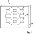
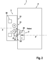
- FIG 1 shows, in connection with Figure 2 , a medical system 1 according to the invention with a wireless power transfer (WPT) system comprising an external charging device 3 and an implantable medical device 2 (e.g. IPG), wherein the charging device 3 includes a primary coil 30, and wherein the implantable medical device 2 implanted in a patient P according to Figure 2 includes a secondary coil 20.
- WPT wireless power transfer
- the charging device 3 includes at least two metal electrodes 31 proximate to the body and adapted to contact the skin of the patient P.
- the electrodes 31 are arranged on a housing surface 33 of the charging device 3.
- the housing surface 33 may also be formed by a flat substrate (e.g. patch or plaster) suitably connected to the rest of the charging device 3.
- the presence of conductors and non-conductors is distinguished on the basis of the impedances, so that it is possible to determine the orientation of the coils 20, 30 with respect to one another.
- the charging device 3 is adapted to output user feedback for the purpose of aligning the charging device 3 or the primary coil 30 over the metallic implant 2 or its secondary coil 20.
- the user feedback can be provided, for example, via a hand-held remote control, via warning tones or the like.
- Figure 3 shows an example of an impedance image that results from calculating the impedances for the segments 32.
- the Z' axis of the secondary coil 20 is too far up and to the right of the center or Z axis of the primary coil 30.
- Another embodiment of the disclosure which is not part of the invention, features a charging device with multiple primary coils in an array. Impedance tomography is used to determine which coil is optimal for activation to achieve high power transfer efficiency. This is the opposite of the single primary coil moving to find the implant; here the correct coil is selected electronically.
- the disclosure allows reliable identification of implant 2 compared to other methods that use multiple sense/search coils to look for disturbances in the excitation field. Impedance tomography may also prove useful for other reasons (e.g., to determine tissue response to the implant, particularly inflammation, scar tissue, etc.).
Landscapes
- Health & Medical Sciences (AREA)
- Engineering & Computer Science (AREA)
- Biomedical Technology (AREA)
- Nuclear Medicine, Radiotherapy & Molecular Imaging (AREA)
- Radiology & Medical Imaging (AREA)
- Life Sciences & Earth Sciences (AREA)
- Animal Behavior & Ethology (AREA)
- General Health & Medical Sciences (AREA)
- Public Health (AREA)
- Veterinary Medicine (AREA)
- Physics & Mathematics (AREA)
- Electromagnetism (AREA)
- Acoustics & Sound (AREA)
- Electrotherapy Devices (AREA)
Claims (9)
- Système médical (1), comprenant :- un dispositif médical implantable (2) comprenant un dispositif de stockage d'énergie destiné à fournir de l'énergie électrique au dispositif médical (2) et une bobine secondaire (20) destinée à transférer l'énergie électrique au dispositif de stockage d'énergie,- un dispositif de chargement (3) qui est conçu pour charger le dispositif de stockage d'énergie, le dispositif de chargement ayant une bobine primaire (30) par l'intermédiaire de laquelle l'énergie électrique peut être transférée au dispositif de stockage d'énergie par l'intermédiaire de la bobine secondaire (20) du dispositif médical implantable (2),caractérisé en ce que
le dispositif de chargement (3) comprend une pluralité d'électrodes métalliques (31) qui sont agencées devant la bobine primaire (30) et sont chacune attribuée à un segment (32) d'une surface de boîtier (33) du dispositif de chargement (3), le dispositif de chargement (3) étant conçu pour utiliser les électrodes métalliques (31) afin de calculer une impédance pour chaque segment (32) et pour utiliser les impédances afin de contrôler si la bobine primaire (30) est alignée pour un transfert d'énergie optimal sur la bobine secondaire (20). - Système médical selon la revendication 1, dans lequel le dispositif de chargement (3) comprend au moins deux électrodes métalliques (31) agencées sur la surface de boîtier (33) et adaptées pour entrer en contact avec la peau d'un patient (P)
- Système médical selon la revendication 1 ou 2, dans lequel la surface de boîtier (33) est formée par un substrat plat connecté à un reste du dispositif de chargement (3).
- Système médical selon la revendication 3, dans lequel le substrat plat est un timbre ou un plâtre.
- Système médical selon l'une des revendications précédentes, dans lequel le dispositif de stockage d'énergie est une batterie.
- Système médical selon l'une des revendications précédentes, dans lequel le dispositif de chargement (3) est adapté pour induire un courant alternatif (I) dans les électrodes métalliques (31) et pour mesurer la tension alternative (V) correspondante induite par ce courant, dans lequel le dispositif de chargement (3) est en outre adapté pour calculer l'impédance complexe (Z = V/I) à partir du courant alternatif (I) et de la tension alternative (V) correspondante pour au moins quatre segments (32) ou pour 16 segments (32) de la surface de boîtier (33).
- Système médical selon la revendication 6, dans lequel sur la base des images qui indiquent les impédances dans les segments individuels (32) une présence de conducteurs et de non conducteurs est distinguée par le système médical sur la base des impédances pour déterminer une orientation des bobines primaire et secondaire (20, 30) l'une par rapport à l'autre.
- Système médical selon l'une des revendications précédentes, dans lequel le dispositif de chargement (3) est adapté pour renvoyer un retour utilisateur dans le but d'aligner la bobine primaire (30) sur la bobine secondaire (20).
- Système médical selon la revendication 8, dans lequel le système médical est adapté pour fournir le retour utilisateur par l'intermédiaire d'une commande à distance portative ou par l'intermédiaire de signaux sonores d'avertissement.
Applications Claiming Priority (3)
| Application Number | Priority Date | Filing Date | Title |
|---|---|---|---|
| US202163221526P | 2021-07-14 | 2021-07-14 | |
| DE202021104268.0U DE202021104268U1 (de) | 2021-08-10 | 2021-08-10 | Impedanztomographiesystem zur Ausrichtungsrückmeldung eines Ladegerätes für ein implantierbares medizinisches Gerät |
| PCT/EP2022/069540 WO2023285503A2 (fr) | 2021-07-14 | 2022-07-13 | Système de tomographie par impédance permettant un retour d'alignement d'un dispositif de charge pour un dispositif médical implantable |
Publications (2)
| Publication Number | Publication Date |
|---|---|
| EP4370200A2 EP4370200A2 (fr) | 2024-05-22 |
| EP4370200B1 true EP4370200B1 (fr) | 2025-03-05 |
Family
ID=82839436
Family Applications (1)
| Application Number | Title | Priority Date | Filing Date |
|---|---|---|---|
| EP22751317.3A Active EP4370200B1 (fr) | 2021-07-14 | 2022-07-13 | Système de tomographie par impédance permettant un retour d'alignement d'un dispositif de charge pour un dispositif médical implantable |
Country Status (3)
| Country | Link |
|---|---|
| US (1) | US20240285958A1 (fr) |
| EP (1) | EP4370200B1 (fr) |
| WO (1) | WO2023285503A2 (fr) |
Family Cites Families (7)
| Publication number | Priority date | Publication date | Assignee | Title |
|---|---|---|---|---|
| US6212430B1 (en) * | 1999-05-03 | 2001-04-03 | Abiomed, Inc. | Electromagnetic field source with detection of position of secondary coil in relation to multiple primary coils |
| US20050187590A1 (en) * | 2003-05-11 | 2005-08-25 | Boveja Birinder R. | Method and system for providing therapy for autism by providing electrical pulses to the vagus nerve(s) |
| WO2009055579A1 (fr) * | 2007-10-26 | 2009-04-30 | Medtronic, Inc. | Recharge longue portée en boucle fermée |
| WO2010042054A1 (fr) * | 2008-10-10 | 2010-04-15 | Milux Holding S.A. | Chargeur pour implant |
| US9878170B2 (en) * | 2013-03-15 | 2018-01-30 | Globus Medical, Inc. | Spinal cord stimulator system |
| US10707692B2 (en) | 2017-01-26 | 2020-07-07 | Medtronic, Inc. | Recharge of implanted medical devices |
| JP2021517502A (ja) | 2018-03-13 | 2021-07-26 | オーグメンテッド バイオニクス ピーティーワイ リミテッド | 感覚刺激装置 |
-
2022
- 2022-07-13 EP EP22751317.3A patent/EP4370200B1/fr active Active
- 2022-07-13 WO PCT/EP2022/069540 patent/WO2023285503A2/fr not_active Ceased
- 2022-07-13 US US18/572,014 patent/US20240285958A1/en active Pending
Also Published As
| Publication number | Publication date |
|---|---|
| WO2023285503A2 (fr) | 2023-01-19 |
| US20240285958A1 (en) | 2024-08-29 |
| WO2023285503A3 (fr) | 2023-02-23 |
| EP4370200A2 (fr) | 2024-05-22 |
Similar Documents
| Publication | Publication Date | Title |
|---|---|---|
| US8473066B2 (en) | External charger for a medical implantable device using field sensing coils to improve coupling | |
| EP2442430B1 (fr) | Dispositif d'alimentation électrique, procédé d'alimentation électrique et système d'alimentation électrique | |
| US6473652B1 (en) | Method and apparatus for locating implanted receiver and feedback regulation between subcutaneous and external coils | |
| US9571166B2 (en) | Testing tuned circuits | |
| AU2017286410B2 (en) | External charger for an implantable medical device having at least one sense coil concentric with a charging coil for determining position | |
| AU2017286411B2 (en) | External charger for an implantable medical device having alignment and centering capabilities | |
| CN109310866B (zh) | 用从至少一个感测线圈确定的谐振频率定位并优化功率传输的可植入医疗设备的外部充电器 | |
| CN115276254B (zh) | 用于向可植入医疗设备(imd)无线地提供能量的外部充电器 | |
| US20190379232A1 (en) | Wireless charging system | |
| US10632318B2 (en) | External charger with three-axis magnetic field sensor to determine implantable medical device position | |
| AU2023233662B2 (en) | Automatically-aligning magnetic field system | |
| US20240285958A1 (en) | Impedance tomography system for alignment feedback of a charging device for an implantable medical device | |
| US20250260266A1 (en) | Method and apparatus for pre-alignment of an automatically aligning magnetic field system | |
| AU2013251210B2 (en) | An improved external charger for a medical implantable device using field sensing coils to improve coupling | |
| JP2025138080A (ja) | インプランタブルデバイスシステム | |
| EP2408524A1 (fr) | Electrode de suivi de rayonnement dotée d'un dispositif de positionnement et d'une unité d'identification |
Legal Events
| Date | Code | Title | Description |
|---|---|---|---|
| STAA | Information on the status of an ep patent application or granted ep patent |
Free format text: STATUS: UNKNOWN |
|
| STAA | Information on the status of an ep patent application or granted ep patent |
Free format text: STATUS: THE INTERNATIONAL PUBLICATION HAS BEEN MADE |
|
| PUAI | Public reference made under article 153(3) epc to a published international application that has entered the european phase |
Free format text: ORIGINAL CODE: 0009012 |
|
| STAA | Information on the status of an ep patent application or granted ep patent |
Free format text: STATUS: REQUEST FOR EXAMINATION WAS MADE |
|
| 17P | Request for examination filed |
Effective date: 20240104 |
|
| AK | Designated contracting states |
Kind code of ref document: A2 Designated state(s): AL AT BE BG CH CY CZ DE DK EE ES FI FR GB GR HR HU IE IS IT LI LT LU LV MC MK MT NL NO PL PT RO RS SE SI SK SM TR |
|
| DAV | Request for validation of the european patent (deleted) | ||
| DAX | Request for extension of the european patent (deleted) | ||
| GRAP | Despatch of communication of intention to grant a patent |
Free format text: ORIGINAL CODE: EPIDOSNIGR1 |
|
| STAA | Information on the status of an ep patent application or granted ep patent |
Free format text: STATUS: GRANT OF PATENT IS INTENDED |
|
| INTG | Intention to grant announced |
Effective date: 20241106 |
|
| GRAS | Grant fee paid |
Free format text: ORIGINAL CODE: EPIDOSNIGR3 |
|
| GRAA | (expected) grant |
Free format text: ORIGINAL CODE: 0009210 |
|
| STAA | Information on the status of an ep patent application or granted ep patent |
Free format text: STATUS: THE PATENT HAS BEEN GRANTED |
|
| AK | Designated contracting states |
Kind code of ref document: B1 Designated state(s): AL AT BE BG CH CY CZ DE DK EE ES FI FR GB GR HR HU IE IS IT LI LT LU LV MC MK MT NL NO PL PT RO RS SE SI SK SM TR |
|
| REG | Reference to a national code |
Ref country code: GB Ref legal event code: FG4D |
|
| REG | Reference to a national code |
Ref country code: CH Ref legal event code: EP |
|
| REG | Reference to a national code |
Ref country code: IE Ref legal event code: FG4D |
|
| REG | Reference to a national code |
Ref country code: DE Ref legal event code: R096 Ref document number: 602022011512 Country of ref document: DE |
|
| P01 | Opt-out of the competence of the unified patent court (upc) registered |
Free format text: CASE NUMBER: APP_12847/2025 Effective date: 20250314 |
|
| PG25 | Lapsed in a contracting state [announced via postgrant information from national office to epo] |
Ref country code: RS Free format text: LAPSE BECAUSE OF FAILURE TO SUBMIT A TRANSLATION OF THE DESCRIPTION OR TO PAY THE FEE WITHIN THE PRESCRIBED TIME-LIMIT Effective date: 20250605 |
|
| PG25 | Lapsed in a contracting state [announced via postgrant information from national office to epo] |
Ref country code: FI Free format text: LAPSE BECAUSE OF FAILURE TO SUBMIT A TRANSLATION OF THE DESCRIPTION OR TO PAY THE FEE WITHIN THE PRESCRIBED TIME-LIMIT Effective date: 20250305 |
|
| REG | Reference to a national code |
Ref country code: NL Ref legal event code: MP Effective date: 20250305 |
|
| PG25 | Lapsed in a contracting state [announced via postgrant information from national office to epo] |
Ref country code: ES Free format text: LAPSE BECAUSE OF FAILURE TO SUBMIT A TRANSLATION OF THE DESCRIPTION OR TO PAY THE FEE WITHIN THE PRESCRIBED TIME-LIMIT Effective date: 20250305 |
|
| REG | Reference to a national code |
Ref country code: LT Ref legal event code: MG9D |
|
| PG25 | Lapsed in a contracting state [announced via postgrant information from national office to epo] |
Ref country code: NO Free format text: LAPSE BECAUSE OF FAILURE TO SUBMIT A TRANSLATION OF THE DESCRIPTION OR TO PAY THE FEE WITHIN THE PRESCRIBED TIME-LIMIT Effective date: 20250605 |
|
| PG25 | Lapsed in a contracting state [announced via postgrant information from national office to epo] |
Ref country code: HR Free format text: LAPSE BECAUSE OF FAILURE TO SUBMIT A TRANSLATION OF THE DESCRIPTION OR TO PAY THE FEE WITHIN THE PRESCRIBED TIME-LIMIT Effective date: 20250305 |
|
| PG25 | Lapsed in a contracting state [announced via postgrant information from national office to epo] |
Ref country code: LV Free format text: LAPSE BECAUSE OF FAILURE TO SUBMIT A TRANSLATION OF THE DESCRIPTION OR TO PAY THE FEE WITHIN THE PRESCRIBED TIME-LIMIT Effective date: 20250305 |
|
| PG25 | Lapsed in a contracting state [announced via postgrant information from national office to epo] |
Ref country code: BG Free format text: LAPSE BECAUSE OF FAILURE TO SUBMIT A TRANSLATION OF THE DESCRIPTION OR TO PAY THE FEE WITHIN THE PRESCRIBED TIME-LIMIT Effective date: 20250305 Ref country code: GR Free format text: LAPSE BECAUSE OF FAILURE TO SUBMIT A TRANSLATION OF THE DESCRIPTION OR TO PAY THE FEE WITHIN THE PRESCRIBED TIME-LIMIT Effective date: 20250606 |
|
| PG25 | Lapsed in a contracting state [announced via postgrant information from national office to epo] |
Ref country code: NL Free format text: LAPSE BECAUSE OF FAILURE TO SUBMIT A TRANSLATION OF THE DESCRIPTION OR TO PAY THE FEE WITHIN THE PRESCRIBED TIME-LIMIT Effective date: 20250305 |
|
| PG25 | Lapsed in a contracting state [announced via postgrant information from national office to epo] |
Ref country code: SE Free format text: LAPSE BECAUSE OF FAILURE TO SUBMIT A TRANSLATION OF THE DESCRIPTION OR TO PAY THE FEE WITHIN THE PRESCRIBED TIME-LIMIT Effective date: 20250305 |
|
| PG25 | Lapsed in a contracting state [announced via postgrant information from national office to epo] |
Ref country code: SM Free format text: LAPSE BECAUSE OF FAILURE TO SUBMIT A TRANSLATION OF THE DESCRIPTION OR TO PAY THE FEE WITHIN THE PRESCRIBED TIME-LIMIT Effective date: 20250305 |
|
| PG25 | Lapsed in a contracting state [announced via postgrant information from national office to epo] |
Ref country code: PT Free format text: LAPSE BECAUSE OF FAILURE TO SUBMIT A TRANSLATION OF THE DESCRIPTION OR TO PAY THE FEE WITHIN THE PRESCRIBED TIME-LIMIT Effective date: 20250707 |
|
| PGFP | Annual fee paid to national office [announced via postgrant information from national office to epo] |
Ref country code: DE Payment date: 20250722 Year of fee payment: 4 |
|
| PG25 | Lapsed in a contracting state [announced via postgrant information from national office to epo] |
Ref country code: PL Free format text: LAPSE BECAUSE OF FAILURE TO SUBMIT A TRANSLATION OF THE DESCRIPTION OR TO PAY THE FEE WITHIN THE PRESCRIBED TIME-LIMIT Effective date: 20250305 Ref country code: IT Free format text: LAPSE BECAUSE OF FAILURE TO SUBMIT A TRANSLATION OF THE DESCRIPTION OR TO PAY THE FEE WITHIN THE PRESCRIBED TIME-LIMIT Effective date: 20250305 |
|
| PG25 | Lapsed in a contracting state [announced via postgrant information from national office to epo] |
Ref country code: AT Free format text: LAPSE BECAUSE OF FAILURE TO SUBMIT A TRANSLATION OF THE DESCRIPTION OR TO PAY THE FEE WITHIN THE PRESCRIBED TIME-LIMIT Effective date: 20250305 |
|
| PGFP | Annual fee paid to national office [announced via postgrant information from national office to epo] |
Ref country code: FR Payment date: 20250723 Year of fee payment: 4 |
|
| PG25 | Lapsed in a contracting state [announced via postgrant information from national office to epo] |
Ref country code: EE Free format text: LAPSE BECAUSE OF FAILURE TO SUBMIT A TRANSLATION OF THE DESCRIPTION OR TO PAY THE FEE WITHIN THE PRESCRIBED TIME-LIMIT Effective date: 20250305 Ref country code: CZ Free format text: LAPSE BECAUSE OF FAILURE TO SUBMIT A TRANSLATION OF THE DESCRIPTION OR TO PAY THE FEE WITHIN THE PRESCRIBED TIME-LIMIT Effective date: 20250305 |
|
| PG25 | Lapsed in a contracting state [announced via postgrant information from national office to epo] |
Ref country code: RO Free format text: LAPSE BECAUSE OF FAILURE TO SUBMIT A TRANSLATION OF THE DESCRIPTION OR TO PAY THE FEE WITHIN THE PRESCRIBED TIME-LIMIT Effective date: 20250305 |
|
| PG25 | Lapsed in a contracting state [announced via postgrant information from national office to epo] |
Ref country code: SK Free format text: LAPSE BECAUSE OF FAILURE TO SUBMIT A TRANSLATION OF THE DESCRIPTION OR TO PAY THE FEE WITHIN THE PRESCRIBED TIME-LIMIT Effective date: 20250305 |
|
| PG25 | Lapsed in a contracting state [announced via postgrant information from national office to epo] |
Ref country code: IS Free format text: LAPSE BECAUSE OF FAILURE TO SUBMIT A TRANSLATION OF THE DESCRIPTION OR TO PAY THE FEE WITHIN THE PRESCRIBED TIME-LIMIT Effective date: 20250705 |
|
| REG | Reference to a national code |
Ref country code: DE Ref legal event code: R097 Ref document number: 602022011512 Country of ref document: DE |
|
| PLBE | No opposition filed within time limit |
Free format text: ORIGINAL CODE: 0009261 |
|
| STAA | Information on the status of an ep patent application or granted ep patent |
Free format text: STATUS: NO OPPOSITION FILED WITHIN TIME LIMIT |
|
| PG25 | Lapsed in a contracting state [announced via postgrant information from national office to epo] |
Ref country code: DK Free format text: LAPSE BECAUSE OF FAILURE TO SUBMIT A TRANSLATION OF THE DESCRIPTION OR TO PAY THE FEE WITHIN THE PRESCRIBED TIME-LIMIT Effective date: 20250305 |
|
| REG | Reference to a national code |
Ref country code: CH Ref legal event code: L10 Free format text: ST27 STATUS EVENT CODE: U-0-0-L10-L00 (AS PROVIDED BY THE NATIONAL OFFICE) Effective date: 20260114 |
|
| 26N | No opposition filed |
Effective date: 20251208 |
|
| REG | Reference to a national code |
Ref country code: CH Ref legal event code: H13 Free format text: ST27 STATUS EVENT CODE: U-0-0-H10-H13 (AS PROVIDED BY THE NATIONAL OFFICE) Effective date: 20260224 |
|
| PG25 | Lapsed in a contracting state [announced via postgrant information from national office to epo] |
Ref country code: LU Free format text: LAPSE BECAUSE OF NON-PAYMENT OF DUE FEES Effective date: 20250713 |
|
| REG | Reference to a national code |
Ref country code: BE Ref legal event code: MM Effective date: 20250731 |
|
| PG25 | Lapsed in a contracting state [announced via postgrant information from national office to epo] |
Ref country code: BE Free format text: LAPSE BECAUSE OF NON-PAYMENT OF DUE FEES Effective date: 20250731 |
|
| PG25 | Lapsed in a contracting state [announced via postgrant information from national office to epo] |
Ref country code: CH Free format text: LAPSE BECAUSE OF NON-PAYMENT OF DUE FEES Effective date: 20250731 |