EP4370274B1 - Procédé de soudage par court-circuit et dispositif de soudage - Google Patents
Procédé de soudage par court-circuit et dispositif de soudage Download PDFInfo
- Publication number
- EP4370274B1 EP4370274B1 EP22747691.8A EP22747691A EP4370274B1 EP 4370274 B1 EP4370274 B1 EP 4370274B1 EP 22747691 A EP22747691 A EP 22747691A EP 4370274 B1 EP4370274 B1 EP 4370274B1
- Authority
- EP
- European Patent Office
- Prior art keywords
- phase
- circuit
- welding
- short
- welding wire
- Prior art date
- Legal status (The legal status is an assumption and is not a legal conclusion. Google has not performed a legal analysis and makes no representation as to the accuracy of the status listed.)
- Active
Links
Images

Classifications
-
- B—PERFORMING OPERATIONS; TRANSPORTING
- B23—MACHINE TOOLS; METAL-WORKING NOT OTHERWISE PROVIDED FOR
- B23K—SOLDERING OR UNSOLDERING; WELDING; CLADDING OR PLATING BY SOLDERING OR WELDING; CUTTING BY APPLYING HEAT LOCALLY, e.g. FLAME CUTTING; WORKING BY LASER BEAM
- B23K9/00—Arc welding or cutting
- B23K9/06—Arrangements or circuits for starting the arc, e.g. by generating ignition voltage, or for stabilising the arc
- B23K9/073—Stabilising the arc
-
- B—PERFORMING OPERATIONS; TRANSPORTING
- B23—MACHINE TOOLS; METAL-WORKING NOT OTHERWISE PROVIDED FOR
- B23K—SOLDERING OR UNSOLDERING; WELDING; CLADDING OR PLATING BY SOLDERING OR WELDING; CUTTING BY APPLYING HEAT LOCALLY, e.g. FLAME CUTTING; WORKING BY LASER BEAM
- B23K9/00—Arc welding or cutting
- B23K9/09—Arrangements or circuits for arc welding with pulsed current or voltage
-
- B—PERFORMING OPERATIONS; TRANSPORTING
- B23—MACHINE TOOLS; METAL-WORKING NOT OTHERWISE PROVIDED FOR
- B23K—SOLDERING OR UNSOLDERING; WELDING; CLADDING OR PLATING BY SOLDERING OR WELDING; CUTTING BY APPLYING HEAT LOCALLY, e.g. FLAME CUTTING; WORKING BY LASER BEAM
- B23K9/00—Arc welding or cutting
- B23K9/095—Monitoring or automatic control of welding parameters
- B23K9/0953—Monitoring or automatic control of welding parameters using computing means
-
- B—PERFORMING OPERATIONS; TRANSPORTING
- B23—MACHINE TOOLS; METAL-WORKING NOT OTHERWISE PROVIDED FOR
- B23K—SOLDERING OR UNSOLDERING; WELDING; CLADDING OR PLATING BY SOLDERING OR WELDING; CUTTING BY APPLYING HEAT LOCALLY, e.g. FLAME CUTTING; WORKING BY LASER BEAM
- B23K9/00—Arc welding or cutting
- B23K9/10—Other electric circuits therefor; Protective circuits; Remote controls
- B23K9/1006—Power supply
- B23K9/1043—Power supply characterised by the electric circuit
- B23K9/1056—Power supply characterised by the electric circuit by using digital means
-
- B—PERFORMING OPERATIONS; TRANSPORTING
- B23—MACHINE TOOLS; METAL-WORKING NOT OTHERWISE PROVIDED FOR
- B23K—SOLDERING OR UNSOLDERING; WELDING; CLADDING OR PLATING BY SOLDERING OR WELDING; CUTTING BY APPLYING HEAT LOCALLY, e.g. FLAME CUTTING; WORKING BY LASER BEAM
- B23K9/00—Arc welding or cutting
- B23K9/12—Automatic feeding or moving of electrodes or work for spot or seam welding or cutting
- B23K9/124—Circuits or methods for feeding welding wire
- B23K9/125—Feeding of electrodes
-
- B—PERFORMING OPERATIONS; TRANSPORTING
- B23—MACHINE TOOLS; METAL-WORKING NOT OTHERWISE PROVIDED FOR
- B23K—SOLDERING OR UNSOLDERING; WELDING; CLADDING OR PLATING BY SOLDERING OR WELDING; CUTTING BY APPLYING HEAT LOCALLY, e.g. FLAME CUTTING; WORKING BY LASER BEAM
- B23K9/00—Arc welding or cutting
- B23K9/16—Arc welding or cutting making use of shielding gas
- B23K9/173—Arc welding or cutting making use of shielding gas and of a consumable electrode
Definitions
- the invention relates to a welding device for carrying out an above-mentioned short-circuit welding method with successive welding cycles, each having an arc phase and a short-circuit phase, wherein the welding device has a welding torch.
- Short-circuit welding processes of the type described above include, in particular, so-called CMT (Cold Metal Transfer) welding processes.
- CMT Cold Metal Transfer
- a welding wire made of meltable material is subjected to a welding current and is alternately moved towards the workpiece and away from it again in order to produce a weld seam or coating. moved.
- the short circuit phase there is a short circuit between the workpiece and the welding wire, which supports the transfer of material from the welding wire to the workpiece.
- the short circuit phase ends and the arc phase begins.
- heat energy is introduced into the welding wire and the workpiece.
- the melting welding wire is conveyed to the workpiece (arc phase) or away from it (short circuit phase) according to a predetermined sequence at fixed speeds and for fixed times. This is known, for example, from the EP 3 292 936 A1 .
- the welding wire is brought to a reverse final speed, which is then reduced again in order to feed the welding wire at a forward final speed in the direction of the workpiece.
- the times in which the welding wire is fed at the final speeds in the respective phases are set in advance. The times are triggered by the onset and breaking of the short circuit.
- the welding wire speed should not be set too high at the time of the short circuit in order to avoid further irregularities in the welding frequency and undesirable effects, such as the welding wire touching the unmelted base material, vibrations in the weld pool and the welding wire "sticking" for a short time. It would therefore be desirable to select the speed of the welding wire in such a way that the welding frequency is as high and, above all, as stable as possible, resulting in high welding quality and avoiding welding spatter.
- the ideal speeds and durations at which the welding wire should be fed at the forward and reverse speeds in the respective phases to stabilize the welding frequency and avoid welding spatter depend on the shape of the weld, the temperature, contamination, the material of the workpiece and other parameters and are therefore difficult to determine. It is therefore not easy, given the current state of the art, to select or achieve the ideal durations or speed profiles for a welding wire in a short-circuit welding process.
- the object of the present invention to alleviate the disadvantages of the prior art or even to eliminate them completely.
- the object of the invention is to keep the welding frequency of a short-circuit welding process as stable as possible in order to improve the welding quality.
- the first time duration of the first backward conveying phase is adjusted by means of a control and/or regulation in such a way that the welding wire does not exceed a predetermined reduced backward speed in the second backward conveying phase at the time the short circuit is broken.
- the first time duration is preferably adjusted by the control and/or regulation in such a way that the welding wire essentially has the predetermined reduced backward speed in the second backward conveying phase at the time the short circuit is broken.
- the first backward conveying phase and thus the conveying of the welding wire at the final backward speed is ended in good time before the short circuit is broken and the reduction of the backward speed of the welding wire begins so that the welding wire is not conveyed too quickly when the material is delivered to the workpiece and welding spatter is thus avoided.
- the control and/or regulation therefore ensures that the backward speed of the welding wire is reduced if it is too high.
- the control and/or regulation ensures that the welding wire in the second reverse feed phase is set to a lower reverse speed value at the time the short circuit is broken, which does not exceed the predetermined reduced reverse speed value. This stabilizes the welding frequency.
- the absolute value of the predetermined reduced reverse speed is lower than the absolute value of the final reverse speed.
- the first time period of the first reverse feed phase is variably adjustable and is adjusted by the control and/or regulation.
- the breaking of the short circuit, as well as the onset of the short circuit, is preferably detected by measuring the welding voltage.
- Typical values for the first time period are, for example, between 1 ms and 10 ms, preferably between 2 and 3 ms with values for the welding frequency between 5 Hz and 200 Hz, preferably between 80 Hz and 150 Hz.
- the adjustment of the first time period by the control and/or regulation can take place from welding cycle to welding cycle or, in some embodiments of the invention, also within a welding cycle. By adjusting the first time period, the first reverse conveying phase shortened or extended.
- the first time period of the first reverse feed phase can be shortened accordingly. If, for example, it is determined that the welding wire is being fed too slowly at the time the short circuit is broken, the first time period of the first reverse feed phase can be extended accordingly.
- the first reverse feed phase begins at the time the welding wire changes from a forward speed to a reverse speed. In the first reverse feed phase, the welding wire is accelerated to the final reverse speed. When the final reverse speed is reached, the acceleration of the welding wire can be stopped and the speed of the welding wire can be kept essentially constant. Preferably, an essentially constant acceleration takes place in the first reverse feed phase.
- the first reverse feed phase is immediately followed by the second reverse feed phase, in which the reverse speed is reduced again by accelerating ("braking") the welding wire (now in the opposite direction).
- Reduction of the reverse speed is understood to mean a reduction in the absolute value and thus a slowing down of the backward movement of the welding wire.
- the short circuit is preferably broken in the second reverse conveying phase, with the control and/or regulation ensuring that the welding wire does not exceed the predetermined reduced reverse speed at the time the short circuit is broken. It is preferred if the control and/or regulation ensures that the welding wire corresponds to the predetermined reduced reverse speed at the time the short circuit is broken.
- the acceleration of the welding wire can be stopped for a holding period. The acceleration can then be continued in the second reverse conveying phase.
- the second reverse conveying phase can be followed by the first forward conveying phase, in which the welding wire is brought to a final forward speed.
- the first forward conveying phase is followed by the second forward conveying phase, in which the forward speed is reduced again by accelerating the welding wire.
- the second forward conveying phase again follows the first backward conveying phase.
- a welding cycle therefore consists of the first and second backward conveying phases and of the first and second forward conveying phases in this order.
- the amount of the backward final speed and/or the amount of the forward final speed can be, for example, between 10 m/min and 70 m/min, in particular between 20 m/min and 60 m/min. In this disclosure, forward speeds have a positive or no sign. To distinguish them, backward speeds are given a negative sign.
- the forward speeds and the backward speeds are selected such that, on average, a forward speed in the direction of the workpiece results over several welding cycles. In other words, the integral over the speed curve over several welding cycles is positive. This is necessary because the melting welding wire releases material to the workpiece to form a weld seam or a coating.
- Typical acceleration values of the welding wire are, for example, in the range between 30,000 m/min/s and 60,000 m/min/s.
- the welding wire is preferably fed by an electric motor, in particular a gearless direct drive.
- the second reverse conveying phase has a first intermediate plateau phase with a substantially constant reverse speed, wherein the welding wire is preferably conveyed away from the workpiece in the first intermediate plateau phase at the predetermined reduced reverse speed.
- the intermediate plateau phase interrupts the acceleration with which the reverse speed of the welding wire is reduced.
- the first time period is adjusted by the control and/or regulation in such a way that the short circuit is broken in the first intermediate plateau phase.
- the acceleration of the welding wire can be suspended for a certain holding period before the acceleration of the welding wire is continued in the second backward conveying phase. After the holding period, the welding wire can be accelerated further until the welding wire is finally conveyed at a forward (final) speed.
- a control system for adjusting the first time period wherein the control is carried out by a control loop with a controller, in particular a P or PI controller, wherein the control adjusts the first time period so that the first intermediate plateau phase corresponds to a first target duration. It is preferred if a manipulated variable of the control loop is formed by the first time period and a reference variable of the control loop is formed by the first target duration of the first intermediate plateau phase.
- the time period of the first intermediate plateau phase can serve as the measured controlled variable.
- the controller adjusts the first time period such that the short circuit is broken in the first intermediate plateau phase.
- the first target duration specifies how long the first intermediate plateau phase should last.
- the first target duration can be between 0.5 ms and 1.5 ms, for example.
- a reference variable can also be referred to as the target variable for the control loop.
- the controller adjusts the first time period from welding cycle to welding cycle. If there is a deviation between the first target duration and the actual duration of the first intermediate plateau phase, the first duration of the first reverse feed phase is adjusted in the next welding cycle. If the actual duration of the first intermediate plateau phase is, the first duration of the first reverse feed phase is shortened. If the actual duration of the first intermediate plateau phase is too long, the first duration of the first reverse feed phase is extended.
- the control system can preferably have parameterizable filters.
- a filter can, for example, determine the maximum rate of change or the edge steepness (slew rate).
- a Filter can be formed, for example, by a PT1 element.
- a control system for adjusting the first time period, wherein the control is carried out by a control loop with a controller, in particular a P or PI controller, wherein a manipulated variable of the control loop is formed by the first time period, a reference variable of the control loop is formed by a target reverse speed of the welding wire, in particular the predetermined reduced reverse speed, and a measured controlled variable of the control loop is formed by a measured reverse speed of the welding wire at the time the short circuit is broken. If the measured reverse speed of the welding wire deviates from the target reverse speed at the time the short circuit is broken, the first time period is adjusted in the next welding cycle.
- a controller in particular a P or PI controller
- the first time period of the first reverse feed phase is shortened or lengthened in the next welding cycle.
- the speed of the welding wire at the time the short circuit is broken can be measured.
- a resistance value is continuously determined from a welding current and a welding voltage and a forecast of the time at which the short circuit will break is made from the resistance value, wherein the first time period is adjusted on the basis of the forecast by starting the second reverse feed phase.
- the continuously determined resistance value allows conclusions to be drawn about the imminent break of the short circuit.
- the first reverse feed phase is ended and the reverse feed speed of the welding wire is reduced so that the welding wire does not exceed the predetermined reduced reverse speed at the time the short circuit breaks or essentially corresponds to it.
- the first The reverse feed phase is terminated in such a timely manner that the short circuit is broken in the first intermediate plateau phase. In this embodiment, the adjustment of the first time period therefore takes place within one welding cycle.
- the forecast is created on the basis of a predetermined resistance threshold value or on the basis of a resistance change rate.
- the first reverse conveying phase can be terminated if the continuously determined resistance value exceeds the predetermined resistance threshold value or the resistance change rate exceeds a predetermined resistance change rate threshold value.
- a particularly efficient embodiment of the invention results when the first backward conveying phase has a first end plateau phase in which the welding wire is conveyed at a substantially constant backward end speed and a time duration of the first end plateau phase is adjusted by the control and/or regulation.
- the adjustment of the first time duration of the backward conveying phase takes place by adjusting the time duration of the first end plateau phase.
- the previous statements relate to the short-circuit phase of the short-circuit welding process.
- the process steps described so far can be applied analogously to the arc phase and the occurrence of the short circuit.
- the second time period of the first forward feed phase is adjusted by means of a further control and/or regulation such that the welding wire in the second forward feed phase does not exceed a predetermined reduced forward speed at the time the short circuit occurs.
- the first forward feed phase is shortened or lengthened so that the welding wire in the second forward feed phase does not exceed the predetermined reduced forward speed at the time the short circuit breaks or essentially corresponds to it.
- the second forward feed phase follows immediately after the first Forward conveying phase.
- the predetermined reduced forward speed is lower in comparison to the final forward speed.
- the second forward conveying phase has a second intermediate plateau phase with a substantially constant forward speed, wherein the welding wire is preferably conveyed at the predetermined reduced forward speed in the second intermediate plateau phase.
- the second time period is adapted by the further control and/or regulation in such a way that the short circuit occurs in the first intermediate plateau phase.
- a further control is therefore provided for adjusting the second time period, wherein the further control is carried out by a further control loop with a further controller, in particular a P or PI controller, wherein the further control adjusts the second time period so that the second intermediate plateau phase has a second target duration. It is preferred if a manipulated variable of the further control loop is formed by the second time period and a reference variable of the further control loop is formed by the second target duration of the second intermediate plateau phase.
- the further controller adjusts the second time period such that the short circuit occurs in the second intermediate plateau phase.
- the second target duration specifies how long the second intermediate plateau phase should last.
- the second target duration of the second intermediate plateau phase can be between 0.5 ms and 2 ms, for example.
- a reference variable can also be referred to as a target variable for the control loop.
- the further controller adjusts the second time period from welding cycle to welding cycle. If there is a deviation between the second target duration and the actual duration of the second intermediate plateau phase, the second duration of the second forward conveying phase is adjusted in the next welding cycle.
- the second target duration is specified and the second duration is adjusted in such a way that the second intermediate plateau phase the second target duration. For example, if the actual duration of the second intermediate plateau phase is too short, the second duration of the first forward conveying phase is shortened. For example, if the actual duration of the second intermediate plateau phase is too long, the second duration of the second forward conveying phase is extended.
- a further control is provided for adjusting the second time period, wherein the further control is carried out by a further control loop with a further controller, in particular a P or PI controller, wherein a manipulated variable of the further control loop is formed by the second time period, a reference variable of the further control loop is formed by a target forward speed of the welding wire, in particular the predetermined reduced forward speed, and a measured controlled variable of the further control loop is formed by the forward speed of the welding wire at the time the short circuit occurs. If the forward speed of the welding wire deviates from the target forward speed, the second time period is adjusted in the next welding cycle. If the welding wire has a forward speed that is too high or too low at the time the short circuit occurs, the second time period of the second forward feed phase is shortened or lengthened in the next welding cycle. The speed of the welding wire at the time the short circuit occurs can be measured.
- a particularly efficient embodiment of the invention results when the first forward conveying phase has a second end plateau phase in which the welding wire is conveyed at a substantially constant forward end speed and a time duration of the second end plateau phase is adjusted by the further control and/or regulation.
- the adjustment of the second time duration of the forward conveying phase takes place by adjusting the time duration of the second end plateau phase.
- the welding device can have a wire feed unit which is designed to feed the welding wire.
- the welding device can have an electric motor, in particular a gearless direct drive.
- the control and/or regulation therefore ensures that the forward speed of the welding wire is reduced if it is too high.
- the control and/or regulation ensures that the welding wire in the second forward feed phase is set to a lower forward speed value at the time the short circuit occurs, which does not exceed the specified reduced forward speed value.
- Fig. 1 shows a welding device 1 with a welding torch 2, which is designed to carry out a short-circuit welding process, in particular a CMT welding process.
- a melting welding wire 3 (electrode) is moved alternately in the direction of a workpiece 5 and back by a conveyor device 4, which can have an electric motor.
- a short-circuit welding process can be divided into arc phases 6 and short-circuit phases 7 (see for example Fig. 2 and 3 ).
- the welding device 1 has a control/regulation unit 8 for controlling and/or regulating the welding wire 3.
- the welding wire 3 is guided from a storage drum 9 into the area of the welding torch 2.
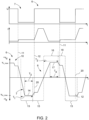
- Fig. 2 shows (below a time profile of a welding voltage U and a time profile of a welding current I) a speed profile 10 of a welding wire 3 in a short-circuit welding process from the prior art with fixed and pre-set time sequences.
- the speed v d is plotted on the ordinate, where +v d denotes a forward speed of the welding wire 3 in the direction of the workpiece 5 and - v d denotes a backward speed of the welding wire 3 away from the workpiece 5.
- the short-circuit welding process can be divided into arc phases 6 and short-circuit phases 7.
- a short-circuit phase 7 begins with the occurrence 11 of the short circuit between the welding wire 3 and the workpiece 5 when the welding wire 3 touches the workpiece 5.
- An arc phase 6 begins with the breaking 12 of the short circuit between the welding wire 3 and the workpiece 5 and ends again when it occurs.
- the welding wire 3 is mainly fed in the direction of the workpiece 5 at a forward speed +v d .
- the welding wire 3 is mainly fed away from the workpiece 5 at a backward speed -v d .
- a welding cycle consists of an arc phase 6 and a short-circuit phase 7.
- the speed curve 10 of the welding wire 3 can be further divided into individual welding wire speed phases with which the welding wire 3 is conveyed.
- a first backward conveying phase 13 the welding wire 3 is accelerated to a final backward speed v re_max .
- the final backward speed v re_max can, for example, be in the range between 10 m/min and 60 m/min, in particular between 20 m/min and 60 m/min.
- the first backward conveying phase 13 has a total duration which is referred to as the first time period T 1 and which can, for example, be 3 ms.
- first final plateau phase 14 with an essentially constant final backward speed v re_max .
- the final plateau phase 14 has the time period T 3 .
- a second backward conveying phase 15 follows, in which the backward speed -v d of the welding wire 3 is reduced again by acceleration.
- the backward speed -v d is reduced to zero in this phase.
- a first forward conveying phase 16 is then provided, in which the welding wire 3 is accelerated to a final forward speed v v_max .
- the total duration of the first forward conveying phase 16 is referred to as the second time period T 2.
- T 4 the time period of which is referred to as T 4 .
- the first forward conveying phase 16 is followed by a second forward conveying phase 18, in which the forward speed +v d is reduced again to zero.
- a first backward conveying phase 13 is then provided again.
- the speed curve shown is a schematic and idealized representation of a target curve. Actual speed curves may differ from the curve shown for physical reasons.
- the speed curve 10 is set over fixed time periods T 1 , T 2 or T 3 , T 4 .
- the first time period T 1 should be set such that the welding wire 3 is fed sufficiently slowly at the time of breaking 12 in order to avoid welding spatter.
- the time of breaking 12 of the short circuit as well as the time of occurrence 11 of the short circuit can vary, however, as shown in Fig. 2 shown, and depend on parameters such as the material, the weld seam, contamination and the temperature etc. Selecting the specified time periods T 1 and T 2 or T 3 , T 4 is therefore not that easy.
- the welding wire 3 is conveyed at too high a reverse conveying speed -v d at the time of breaking 12 of the short circuit, thus causing welding spatter.
- Fig. 2 where the short circuit breaks at times 20 with too high a speed.
- the times 20 vary in time relative to the speed curve 10, as in Fig. 2 is also recognizable.
- the times of occurrence 11 of the short circuit can also vary. Due to the variation in the times of occurrence 11 and breaking 12 of the short circuit, the welding frequency is irregular and therefore not stable.
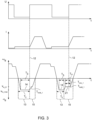
- the first time period T 1 of the first reverse conveying phase 13 is adjusted by means of a control and/or regulation such that the welding wire 3 in the second reverse conveying phase 15 at the time of breaking 12 of the short circuit does not exceed a predetermined reduced reverse speed v re_K , in particular corresponds to this.
- a control and/or regulation can be implemented in the control/regulation unit 8.
- the second backward conveying phase 15 can have a first intermediate plateau phase 21 with a substantially constant backward speed -v d .
- the welding wire 3 is conveyed away from the workpiece 5 in the first intermediate plateau phase 21 at the predetermined reduced backward speed v re_K .
- the control and/or regulation adapts the first time period T 1 in the embodiment shown such that the breaking 12 of the short circuit takes place in the first intermediate plateau phase 21. This can take place within a welding cycle or from welding cycle to welding cycle.
- the predetermined reduced backward speed v re_K of the welding wire 3 is maintained for a holding time period T hold_1 before the acceleration of the welding wire 3 is continued.
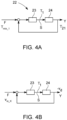
- a block diagram for a control is shown.
- the control is formed by a closed control loop 22 and is designed to adapt the first time period T 1 , in the event of a deviation, from welding cycle to welding cycle, so that the welding wire 3 in the subsequent welding cycle in the second reverse feed phase 15 does not exceed a predetermined reduced reverse speed v re_K at the time of breaking 12 of the short circuit.
- Fig. 3 an adaptation from welding cycle to welding cycle is shown.
- the first time period T 1 can be adjusted so that the short circuit is broken 12 in the first intermediate plateau phase 21.
- the control loop 22 contains a controller 23, which can be designed as a P or PI controller, for example, and the controlled system 24.
- the first time period T 1 is provided as the manipulated variable S in the control loop 22. This can be adjusted by the controller 23.
- the target or reference variable F of the control loop 22 is formed by a first target duration T min_1 of the first intermediate plateau phase 21.
- the duration T 21 of the first intermediate plateau phase 21 is used as the measured controlled variable Y.
- Fig. 4B an alternative embodiment of the control is shown.
- the first time period T 1 is again used as the control variable S of the control circuit 22. This can be adjusted by the controller 23.
- the specified reduced reverse speed v re_K of the welding wire 3, which it should have at the time of breaking 12 of the short circuit is used as the target or reference variable F of the control circuit 22.
- the measured reverse speed -v d of the welding wire 3 at the time of breaking 12 of the short circuit is used as the measured control variable Y.
- the controller 23 adjusts the first time period T 1 in the next welding cycle so that the welding wire 3 is fed at the specified reduced reverse speed v re_K when the short circuit is broken 12.
- An adjustment from welding cycle to welding cycle is possible in Fig. 3 shown.
- the first time period T 1 can be adjusted so that the breaking 12 of the short circuit takes place in the first intermediate plateau phase 21.
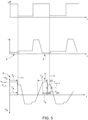
- the second time period T 2 of the first forward feed phase 16 can be adjusted by a further control and/or regulation in a further control/regulation unit 8', so that the welding wire 3 in the second forward feed phase 18 does not exceed a predetermined reduced forward speed v v_K at the time of occurrence 11 of the short circuit.
- Fig. 5 shown in the right arc phase 6.
- the first forward advance phase 16 is therefore terminated in time and the second forward advance phase 18 is initiated before the short circuit occurs 11.
- Fig. 5 also shows a welding current curve and a welding voltage curve.
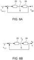
- Fig. 6A a block diagram for a further control is shown.
- the further control is formed by a closed control loop 22' and is designed to change the second time period T 2 , if necessary, from welding cycle to welding cycle. so that the welding wire 3 in the subsequent welding cycle in the second backward conveying phase 18 does not exceed a predetermined reduced forward speed v v_K at the time of occurrence 11 of the short circuit.
- This is in Fig. 5 shown.
- the first time period T 2 can be adjusted so that the onset 11 of the short circuit takes place in a second intermediate plateau phase 25 with a constant, predetermined reduced forward speed v v_K .
- the control loop 22' contains a controller 23, which can be designed as a P or PI controller, for example, and the controlled system 24'.
- the further control loop 22' uses the second time period T 2 as the manipulated variable S. This can be adjusted by the further controller 23'.
- the target or reference variable F of the further control loop 22' is formed by a second target duration T min_2 of the second intermediate plateau phase 25.
- the duration T 25 of the second intermediate plateau phase 25 is used as the measured controlled variable R.
- FIG. 6B an alternative further control loop 22' is shown.
- the second time period T 2 is again used as the control variable S of the further control loop 22'. This can be adjusted by the further controller 23'.
- the specified reduced forward speed v v_K of the welding wire 3, which it should have at the time 11 of the short circuit, is used as the target or reference variable F of the further control loop 22'.
- the measured forward speed v d of the welding wire 3 at the time 11 of the short circuit is used as the measured control variable Y.
- the further controller 23' adjusts the second time period T 2 in the next welding cycle so that the welding wire 3 is fed at the specified reduced forward speed v v_K when the short circuit occurs.
- An adjustment from welding cycle to welding cycle is possible in Fig. 5 shown.
- the second time period T 2 can be adjusted so that the onset 11 of the short circuit takes place in the second intermediate plateau phase 25.
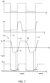
- Fig. 7 shows, below a speed curve 10, a welding voltage curve and a welding current curve, a temporal curve of a resistance value R, on the basis of which the breaking 12 of the short circuit can be predicted.
- the resistance value is calculated from the welding voltage U and the welding current I.
- the first time period T 1 can be adjusted on the basis of the forecast. This can be done within one cycle.
- the adjustment of the first time period T 1 can be done by a controller. If, for example, the resistance value exceeds a resistance threshold value R S or the resistance change rate dR/dt exceeds a predetermined resistance change rate threshold value, the impending breaking 12 of the short circuit can be determined.
- the controller can then end the first reverse feed phase 13 and initiate the second reverse feed phase 15. In this way, the first time period T 1 is adjusted.
Landscapes
- Engineering & Computer Science (AREA)
- Physics & Mathematics (AREA)
- Plasma & Fusion (AREA)
- Mechanical Engineering (AREA)
- Theoretical Computer Science (AREA)
- Arc Welding Control (AREA)
Claims (14)
- Procédé de soudage par court-circuit avec des cycles de soudage successifs, qui comprennent chacun une phase d'arc électrique (6) et une phase de court-circuit (7), avec les étapes suivantes pendant un cycle de soudage :transport d'un fil de soudage à fondre (3) loin d'une pièce (5) pendant la phase de court-circuit (7) avec une vitesse vers l'arrière (-vd), de sorte que le matériau est distribué du fil de soudage (3) à la pièce (5) et un arc électrique est allumé, dans lequel le fil de soudage (3) est amené, pendant la phase de court-circuit (7), dans une première phase de transport vers l'arrière (13) avec une première durée (T1) jusqu'à une vitesse finale vers l'arrière (vre_max) et est transporté avec celle-ci jusqu'au début d'une deuxième phase de transport vers l'arrière (15), dans laquelle la vitesse vers l'arrière (-vd) du fil de soudage (3) est encore réduite, dans lequel la deuxième phase de transport vers l'arrière (15) succède immédiatement à la fin de la première phase de transport vers l'arrière (13) ; ettransport du fil de soudage (3) en direction de la pièce (5) pendant la phase d'arc électrique (6) avec une vitesse vers l'avant (vd), afin d'amener le fil de soudage (3) en contact avec la pièce (5) et de provoquer un court-circuit entre le fil de soudage (3) et la pièce (5), dans lequel le fil de soudage (3) est amené, pendant la phase d'arc électrique (6), dans une première phase de transport vers l'avant (16), avec une deuxième durée (T2) jusqu'à une vitesse finale vers l'avant (vv_max) et est transporté avec celle-ci jusqu'au début d'une deuxième phase de transport vers l'avant (18), dans laquelle la vitesse vers l'avant (vd) du fil de soudage (3) est encore réduite, dans lequel la deuxième phase de transport vers l'avant (18) succède immédiatement à la fin de la première phase de transport vers l'avant (16),caractérisé en ce quela première durée (T1) de la première phase de transport vers l'arrière (13) est adaptée au moyen d'une commande et/ou d'une régulation, de sorte que le fil de soudage (3) ne tombe pas, dans la deuxième phase de transport vers l'arrière (15), au moment de la rupture (12) du court-circuit, en dessous d'une vitesse vers l'arrière réduite (vre_K) prédéterminée, dans lequel l'adaptation de la première durée (T1) permet de raccourcir ou d'allonger la première phase de transport vers l'arrière (13).
- Procédé de soudage par court-circuit selon la revendication 1, caractérisé en ce que la deuxième phase de transport vers l'arrière (15) comprend une première phase de palier intermédiaire (21) avec une vitesse vers l'arrière (-vd) globalement constante, dans lequel le fil de soudage (3) est transporté, dans la première phase de palier intermédiaire (21), de préférence avec la vitesse vers l'arrière réduite (vre_K) prédéterminée loin de la pièce (5).
- Procédé de soudage par court-circuit selon la revendication 2, caractérisé en ce que la première durée (T1) est adaptée par la commande et/ou la régulation de sorte que la rupture (12) du court-circuit a lieu dans la première phase de palier intermédiaire (21).
- Procédé de soudage par court-circuit selon la revendication 3, caractérisé en ce qu'une régulation est prévue pour l'adaptation de la première durée (T1) et la régulation a lieu à l'aide d'un circuit de régulation (22) avec un régulateur (23), plus particulièrement un régulateur P ou PI, dans lequel la régulation adapte la première durée (T1) de sorte que la première phase de palier intermédiaire (21) correspond à une première durée de consigne (Tmin_1).
- Procédé de soudage par court-circuit selon l'une des revendications 1 à 3, caractérisé en ce qu'une régulation est prévue pour l'adaptation de la première durée (T1) et la régulation a lieu à l'aide d'un circuit de régulation (22) avec un régulateur (23), plus particulièrement un régulateur P ou PI, dans lequel une grandeur de réglage (S) du circuit de régulation (22) est constituée de la première durée (T1), une grandeur de guidage (F) du circuit de régulation (22) est constituée d'une vitesse vers l'arrière de consigne du fil de soudage (3), plus particulièrement la vitesse vers l'arrière réduite (vre_K) prédéterminée, et une grandeur de régulation mesurée (Y) du circuit de régulation (22) est constituée d'une vitesse vers l'arrière mesurée (-vd) du fil de soudage (3) au moment de la rupture (12) du court-circuit.
- Procédé de soudage par court-circuit selon l'une des revendications 1 à 3, caractérisé en ce que, de manière continue, une valeur de résistance (R) est déterminée à partir d'un courant de soudage (I) et d'une tension de soudage (U) et un pronostic concernant le moment de la rupture (12) du court-circuit est défini à partir de la valeur de résistance (R), dans lequel la première durée (T1) est adapté sur la base du pronostic, en commençant par la deuxième phase de transport vers l'arrière (15).
- Procédé de soudage par court-circuit selon la revendication 6, caractérisé en ce que le pronostic est défini sur la base d'une valeur seuil de résistance (Rs) prédéterminée ou sur la base d'un taux de variation de résistance (dR/dt).
- Procédé de soudage par court-circuit selon l'une des revendications 1 à 7, caractérisé en ce que la première phase de transport vers l'arrière (13) comprend une première phase de palier final (14), dans laquelle le fil de soudage (3) est transporté avec une vitesse finale vers l'arrière (vre_max) globalement constante et une durée (T3) de la première phase de palier final (14) est adapté par la commande et/ou la régulation.
- Procédé de soudage par court-circuit selon l'une des revendications 1 à 8, caractérisé en ce que la deuxième durée (T2) de la première phase de transport vers l'avant (16) est adaptée au moyen d'une autre commande et/ou régulation de sorte que le fil de soudage (3) ne tombe pas, dans la deuxième phase de transport vers l'avant (18), au moment de l'apparition (11) du court-circuit, en dessous d'une vitesse vers l'avant réduite (Vv_K), dans lequel l'adaptation de la deuxième durée (T2) permet de raccourcir ou d'allonger la première phase de transport vers l'avant (16).
- Procédé de soudage par court-circuit selon la revendication 9, caractérisé en ce que la deuxième phase de transport vers l'avant (18) comprend une deuxième phase de palier intermédiaire (25) avec une vitesse vers l'avant (vd) globalement constante, dans lequel le fil de soudage (3) est transporté, dans la deuxième phase de palier intermédiaire (25), de préférence avec la vitesse vers l'avant réduite (Vv_A) prédéterminée en direction de la pièce (5).
- Procédé de soudage par court-circuit selon la revendication 10, caractérisé en ce que la deuxième durée (T2) est adaptée par l'autre commande et/ou régulation de sorte que l'apparition (11) du court-circuit a lieu dans la deuxième phase de palier intermédiaire (25).
- Procédé de soudage par court-circuit selon la revendication 11, caractérisé en ce qu'une autre régulation est prévue pour l'adaptation de la deuxième durée (T2) et l'autre régulation a lieu à l'aide d'un autre circuit de régulation (22') avec un autre régulateur (23'), plus particulièrement un régulateur P ou PI, dans lequel l'autre régulation adapte la deuxième durée (T2) de sorte que la deuxième phase de palier intermédiaire (25) correspond à une deuxième durée de consigne (Tmin_2).
- Procédé de soudage par court-circuit selon l'une des revendications 9 à 11, caractérisé en ce qu'une autre régulation est prévue pour l'adaptation de la deuxième durée (T2) et l'autre régulation a lieu à l'aide d'un autre circuit de régulation (22') avec un autre régulateur (23'), plus particulièrement un régulateur P ou PI, dans lequel une grandeur de réglage (S) de l'autre circuit de régulation (22') est constituée de la deuxième durée (T2), une grandeur de guidage (F) du circuit de régulation (22') est constituée d'une vitesse vers l'avant de consigne du fil de soudage (3), plus particulièrement la vitesse vers l'avant réduite (vv_K) prédéterminée, et une grandeur de régulation mesurée (Y) de l'autre circuit de régulation (22') est constituée d'une vitesse vers l'avant mesurée (vd) du fil de soudage (3) au moment de l'apparition (11) du court-circuit.
- Dispositif de soudage (1) pour l'exécution d'un procédé de soudage par court-circuit selon l'une des revendications précédentes 1 à 13 avec des cycles de soudage successifs, qui comprennent chacun une phase d'arc électrique (6) et une phase de court-circuit (7), avec un chalumeau de soudage (2), dans lequel le dispositif de soudage (1) est conçupour transporter un fil de soudage à fondre (3) loin de la pièce (5) pendant la phase de court-circuit (7) avec une vitesse vers l'arrière (-vd), de sorte que le matériau du fil de soudage (3) est distribué sur la pièce (5) et qu'un arc électrique est allumé, dans lequel le dispositif de soudage (1) est en outre conçu pour amener le fil de soudage (3), pendant la phase de court-circuit (7), dans une première phase de transport vers l'arrière (13), avec une première durée (T1), à une vitesse finale vers l'arrière (vre_max) et le transporter avec celle-ci jusqu'au début d'une deuxième phase de transport vers l'arrière (15), dans laquelle la vitesse vers l'arrière (-vd) du fil de soudage (3) est encore réduite, dans lequel la deuxième phase de transport vers l'arrière (15) succède immédiatement à la fin de la première phase de transport vers l'arrière (13),et le dispositif de soudage (1) est en outre conçu pour transporter le fil de soudage (3) en direction de la pièce (5) pendant la phase d'arc électrique (6) avec une vitesse vers l'avant (vd), afin de provoquer un court-circuit entre le fil de soudage (3) et la pièce (5), dans lequel le dispositif de soudage (1) est en outre conçu pour amener le fil de soudage (3), pendant la phase d'arc électrique (6), dans une première phase de transport vers l'avant (16), avec une deuxième durée (T2), à une vitesse finale vers l'avant (vv_max) et pour le transporter, avec la vitesse finale vers l'avant (vv_max), jusqu'au début d'une deuxième phase de transport vers l'avant (18), dans laquelle la vitesse vers l'avant (vd) du fil de soudage (3) est encore réduite, dans lequel la deuxième phase de transport vers l'avant (18) succède immédiatement à la fin de la première phase de transport vers l'avant (16),caractérisé en ce queune unité de commande/régulation (8) est prévue, qui est conçue pour adapter la première durée (T1) de la première phase de transport vers l'arrière (13) au moyen d'une commande et/ou régulation de sorte que le fil de soudage (3) ne tombe pas, dans la deuxième phase de transport vers l'arrière (15), au moment de la rupture (12) du court-circuit, en dessous d'une vitesse vers l'arrière réduite (vre_K) prédéterminée, dans lequel l'adaptation de la première durée (T1) permet de raccourcir ou d'allonger la première phase de transport vers l'arrière (13).
Applications Claiming Priority (2)
| Application Number | Priority Date | Filing Date | Title |
|---|---|---|---|
| EP21185397.3A EP4119274A1 (fr) | 2021-07-13 | 2021-07-13 | Procédé de soudage par court-circuit et dispositif de soudage |
| PCT/EP2022/069377 WO2023285416A1 (fr) | 2021-07-13 | 2022-07-12 | Procédé de soudage par court-circuit et dispositif de soudage |
Publications (3)
| Publication Number | Publication Date |
|---|---|
| EP4370274A1 EP4370274A1 (fr) | 2024-05-22 |
| EP4370274C0 EP4370274C0 (fr) | 2025-02-12 |
| EP4370274B1 true EP4370274B1 (fr) | 2025-02-12 |
Family
ID=76920604
Family Applications (2)
| Application Number | Title | Priority Date | Filing Date |
|---|---|---|---|
| EP21185397.3A Withdrawn EP4119274A1 (fr) | 2021-07-13 | 2021-07-13 | Procédé de soudage par court-circuit et dispositif de soudage |
| EP22747691.8A Active EP4370274B1 (fr) | 2021-07-13 | 2022-07-12 | Procédé de soudage par court-circuit et dispositif de soudage |
Family Applications Before (1)
| Application Number | Title | Priority Date | Filing Date |
|---|---|---|---|
| EP21185397.3A Withdrawn EP4119274A1 (fr) | 2021-07-13 | 2021-07-13 | Procédé de soudage par court-circuit et dispositif de soudage |
Country Status (5)
| Country | Link |
|---|---|
| US (1) | US11992904B1 (fr) |
| EP (2) | EP4119274A1 (fr) |
| JP (1) | JP7576717B2 (fr) |
| CN (1) | CN117320830B (fr) |
| WO (1) | WO2023285416A1 (fr) |
Families Citing this family (1)
| Publication number | Priority date | Publication date | Assignee | Title |
|---|---|---|---|---|
| JP7774111B1 (ja) * | 2024-10-04 | 2025-11-20 | 株式会社ダイヘン | パルスアーク溶接制御方法及びパルスアーク溶接電源 |
Family Cites Families (11)
| Publication number | Priority date | Publication date | Assignee | Title |
|---|---|---|---|---|
| AT501489B1 (de) * | 2005-02-25 | 2009-07-15 | Fronius Int Gmbh | Verfahren zum steuern und/oder regeln eines schweissgerätes und schweissgerät |
| US8513568B2 (en) | 2009-06-19 | 2013-08-20 | Panasonic Corporation | Consumable electrode arc welding method and consumable electrode arc welding device |
| JP5538181B2 (ja) | 2010-10-26 | 2014-07-02 | 川崎重工業株式会社 | アーク溶接の制御システムおよび制御方法 |
| EP2732901B1 (fr) * | 2011-07-12 | 2018-08-08 | Panasonic Intellectual Property Management Co., Ltd. | Procédé de commande de soudage à l'arc et dispositif de soudage à l'arc |
| JP6800865B2 (ja) * | 2015-09-30 | 2020-12-16 | 株式会社ダイヘン | アーク溶接装置およびアーク溶接方法 |
| EP3292936A1 (fr) | 2016-09-09 | 2018-03-14 | Fronius International GmbH | Procede de soudage par court-circuit et dispositif d'execution d'un tel procede de soudage par court-circuit |
| CN111989182B (zh) * | 2018-04-18 | 2022-10-18 | 松下知识产权经营株式会社 | 电弧焊接控制方法 |
| EP3599046A1 (fr) | 2018-07-27 | 2020-01-29 | FRONIUS INTERNATIONAL GmbH | Procédé de soudage à l'arc à l'aide d'un fil fusible de soudure |
| JP7188858B2 (ja) * | 2019-02-13 | 2022-12-13 | 株式会社ダイヘン | アーク溶接方法 |
| EP3815828A1 (fr) * | 2019-11-04 | 2021-05-05 | FRONIUS INTERNATIONAL GmbH | Procédé et dispositif de soudage d'un cordon de soudure |
| JP7396779B2 (ja) * | 2019-11-22 | 2023-12-12 | 株式会社ダイヘン | アーク溶接制御方法 |
-
2021
- 2021-07-13 EP EP21185397.3A patent/EP4119274A1/fr not_active Withdrawn
-
2022
- 2022-07-12 JP JP2023577723A patent/JP7576717B2/ja active Active
- 2022-07-12 EP EP22747691.8A patent/EP4370274B1/fr active Active
- 2022-07-12 WO PCT/EP2022/069377 patent/WO2023285416A1/fr not_active Ceased
- 2022-07-12 US US18/283,566 patent/US11992904B1/en active Active
- 2022-07-12 CN CN202280035234.2A patent/CN117320830B/zh active Active
Also Published As
| Publication number | Publication date |
|---|---|
| JP2024525353A (ja) | 2024-07-12 |
| EP4119274A1 (fr) | 2023-01-18 |
| US20240165729A1 (en) | 2024-05-23 |
| CN117320830A (zh) | 2023-12-29 |
| WO2023285416A1 (fr) | 2023-01-19 |
| EP4370274C0 (fr) | 2025-02-12 |
| EP4370274A1 (fr) | 2024-05-22 |
| CN117320830B (zh) | 2024-05-17 |
| JP7576717B2 (ja) | 2024-10-31 |
| US11992904B1 (en) | 2024-05-28 |
Similar Documents
| Publication | Publication Date | Title |
|---|---|---|
| EP2442938B1 (fr) | Procédé de changement d'une opération de soudage au cours d'un procédé de soudage, et procédé d'apport de chaleur avant soudage | |
| DE69117998T2 (de) | Vorrichtung und Verfahren zum Steuern eines Schweisszyklus | |
| EP0369367B1 (fr) | Dispositif et procédé de soudage à l'arc avec court-circuits | |
| EP3509784B2 (fr) | Procédé de soudage par court-circuit | |
| DE202012012969U1 (de) | Vorrichtung zum Kurzschlussschweißen mit Wechselstromwellenform | |
| AT409832B (de) | Schweissverfahren und schweissgerät zur durchführung des schweissverfahrens | |
| DE112013003613T5 (de) | Verfahren und ein System zum Starten und Stoppen eines Warmdrahtsystems | |
| DE19808383A1 (de) | Verfahren zum Metall-Schutzgas-Lichtbogen-Schweißen (MIG/MAG-Schweißen) von zwei oder mehreren Fügepartnern | |
| DE19738785A1 (de) | Elektronische Schweißenergiequelle | |
| EP2359974A2 (fr) | Procédé de soudage à l'arc et source d'électricité de soudage pour la réalisation du procédé | |
| EP2269758B1 (fr) | Procédé de soudage à l'arc à courant continue | |
| EP4370274B1 (fr) | Procédé de soudage par court-circuit et dispositif de soudage | |
| DE102006050297B4 (de) | Impulslichtbogenprozess | |
| EP1253991B1 (fr) | Dispositif et procede de commande de soudage par points | |
| EP3623095A1 (fr) | Appareil de soudage et procédé de soudage à vitesse d'avance du fil de soudage à réglage automatique | |
| EP3755490B1 (fr) | Procédé de soudage à l'arc pourvu d'un fil à souder fusible | |
| EP1944115B1 (fr) | Procédé et dispositif de contrôle de la sortie d'une source de puissance de soudage à l'arc avec électrodes consommables ayant un intervalle de temps avant le rallumage de l'arc | |
| DE3322215C2 (de) | Einrichtung zum Lichtbogenschweißen, insbesondere UP-Lichtbogenschweißen mit mehreren gleichzeitig abschmelzenden Drahtelektroden | |
| EP3903983A1 (fr) | Procédé de soudage et dispositif de soudage permettant de mettre en oeuvre un procédé de soudage | |
| DE10137977C1 (de) | Punktschweiß-Steuervorrichtung | |
| DE3220590A1 (de) | Gleichstromlichtbogenschweissmaschine | |
| EP1412123B1 (fr) | Procede de soudage a l'arc a courte duree et systeme de soudage a l'arc a courte duree | |
| EP4669483B1 (fr) | Procédé de commande et/ou de régulation d'un processus de soudage à l'arc pulsé ainsi que dispositif de soudage pour la mise en oeuvre d'un processus de soudage à l'arc pulsé | |
| EP4079436A1 (fr) | Procédé de commande ou de régulation de la vitesse d'avance d'un fil en matière en fusion dans un procédé de soudage laser ou de brasage laser, ainsi que dispositif de soudage laser ou de brasage laser permettant de mettre en uvre un tel procédé | |
| EP4010142B1 (fr) | Procédé et dispositif de stabilisation d'une transition entre différentes phases d'un procedé de soudage |
Legal Events
| Date | Code | Title | Description |
|---|---|---|---|
| STAA | Information on the status of an ep patent application or granted ep patent |
Free format text: STATUS: UNKNOWN |
|
| STAA | Information on the status of an ep patent application or granted ep patent |
Free format text: STATUS: THE INTERNATIONAL PUBLICATION HAS BEEN MADE |
|
| PUAI | Public reference made under article 153(3) epc to a published international application that has entered the european phase |
Free format text: ORIGINAL CODE: 0009012 |
|
| STAA | Information on the status of an ep patent application or granted ep patent |
Free format text: STATUS: REQUEST FOR EXAMINATION WAS MADE |
|
| 17P | Request for examination filed |
Effective date: 20240119 |
|
| AK | Designated contracting states |
Kind code of ref document: A1 Designated state(s): AL AT BE BG CH CY CZ DE DK EE ES FI FR GB GR HR HU IE IS IT LI LT LU LV MC MK MT NL NO PL PT RO RS SE SI SK SM TR |
|
| GRAP | Despatch of communication of intention to grant a patent |
Free format text: ORIGINAL CODE: EPIDOSNIGR1 |
|
| STAA | Information on the status of an ep patent application or granted ep patent |
Free format text: STATUS: GRANT OF PATENT IS INTENDED |
|
| GRAJ | Information related to disapproval of communication of intention to grant by the applicant or resumption of examination proceedings by the epo deleted |
Free format text: ORIGINAL CODE: EPIDOSDIGR1 |
|
| STAA | Information on the status of an ep patent application or granted ep patent |
Free format text: STATUS: REQUEST FOR EXAMINATION WAS MADE |
|
| DAV | Request for validation of the european patent (deleted) | ||
| DAX | Request for extension of the european patent (deleted) | ||
| INTG | Intention to grant announced |
Effective date: 20240925 |
|
| INTC | Intention to grant announced (deleted) | ||
| GRAP | Despatch of communication of intention to grant a patent |
Free format text: ORIGINAL CODE: EPIDOSNIGR1 |
|
| STAA | Information on the status of an ep patent application or granted ep patent |
Free format text: STATUS: GRANT OF PATENT IS INTENDED |
|
| GRAS | Grant fee paid |
Free format text: ORIGINAL CODE: EPIDOSNIGR3 |
|
| INTG | Intention to grant announced |
Effective date: 20241206 |
|
| GRAA | (expected) grant |
Free format text: ORIGINAL CODE: 0009210 |
|
| STAA | Information on the status of an ep patent application or granted ep patent |
Free format text: STATUS: THE PATENT HAS BEEN GRANTED |
|
| AK | Designated contracting states |
Kind code of ref document: B1 Designated state(s): AL AT BE BG CH CY CZ DE DK EE ES FI FR GB GR HR HU IE IS IT LI LT LU LV MC MK MT NL NO PL PT RO RS SE SI SK SM TR |
|
| REG | Reference to a national code |
Ref country code: GB Ref legal event code: FG4D Free format text: NOT ENGLISH |
|
| REG | Reference to a national code |
Ref country code: CH Ref legal event code: EP |
|
| REG | Reference to a national code |
Ref country code: DE Ref legal event code: R096 Ref document number: 502022002897 Country of ref document: DE |
|
| REG | Reference to a national code |
Ref country code: IE Ref legal event code: FG4D Free format text: LANGUAGE OF EP DOCUMENT: GERMAN |
|
| U01 | Request for unitary effect filed |
Effective date: 20250227 |
|
| U07 | Unitary effect registered |
Designated state(s): AT BE BG DE DK EE FI FR IT LT LU LV MT NL PT RO SE SI Effective date: 20250307 |
|
| PG25 | Lapsed in a contracting state [announced via postgrant information from national office to epo] |
Ref country code: RS Free format text: LAPSE BECAUSE OF FAILURE TO SUBMIT A TRANSLATION OF THE DESCRIPTION OR TO PAY THE FEE WITHIN THE PRESCRIBED TIME-LIMIT Effective date: 20250512 |
|
| PG25 | Lapsed in a contracting state [announced via postgrant information from national office to epo] |
Ref country code: PL Free format text: LAPSE BECAUSE OF FAILURE TO SUBMIT A TRANSLATION OF THE DESCRIPTION OR TO PAY THE FEE WITHIN THE PRESCRIBED TIME-LIMIT Effective date: 20250212 |
|
| PG25 | Lapsed in a contracting state [announced via postgrant information from national office to epo] |
Ref country code: ES Free format text: LAPSE BECAUSE OF FAILURE TO SUBMIT A TRANSLATION OF THE DESCRIPTION OR TO PAY THE FEE WITHIN THE PRESCRIBED TIME-LIMIT Effective date: 20250212 |
|
| PG25 | Lapsed in a contracting state [announced via postgrant information from national office to epo] |
Ref country code: NO Free format text: LAPSE BECAUSE OF FAILURE TO SUBMIT A TRANSLATION OF THE DESCRIPTION OR TO PAY THE FEE WITHIN THE PRESCRIBED TIME-LIMIT Effective date: 20250512 Ref country code: IS Free format text: LAPSE BECAUSE OF FAILURE TO SUBMIT A TRANSLATION OF THE DESCRIPTION OR TO PAY THE FEE WITHIN THE PRESCRIBED TIME-LIMIT Effective date: 20250612 |
|
| PG25 | Lapsed in a contracting state [announced via postgrant information from national office to epo] |
Ref country code: HR Free format text: LAPSE BECAUSE OF FAILURE TO SUBMIT A TRANSLATION OF THE DESCRIPTION OR TO PAY THE FEE WITHIN THE PRESCRIBED TIME-LIMIT Effective date: 20250212 |
|
| PG25 | Lapsed in a contracting state [announced via postgrant information from national office to epo] |
Ref country code: GR Free format text: LAPSE BECAUSE OF FAILURE TO SUBMIT A TRANSLATION OF THE DESCRIPTION OR TO PAY THE FEE WITHIN THE PRESCRIBED TIME-LIMIT Effective date: 20250513 |
|
| U20 | Renewal fee for the european patent with unitary effect paid |
Year of fee payment: 4 Effective date: 20250725 |
|
| PG25 | Lapsed in a contracting state [announced via postgrant information from national office to epo] |
Ref country code: SM Free format text: LAPSE BECAUSE OF FAILURE TO SUBMIT A TRANSLATION OF THE DESCRIPTION OR TO PAY THE FEE WITHIN THE PRESCRIBED TIME-LIMIT Effective date: 20250212 |
|
| PG25 | Lapsed in a contracting state [announced via postgrant information from national office to epo] |
Ref country code: CZ Free format text: LAPSE BECAUSE OF FAILURE TO SUBMIT A TRANSLATION OF THE DESCRIPTION OR TO PAY THE FEE WITHIN THE PRESCRIBED TIME-LIMIT Effective date: 20250212 |
|
| PG25 | Lapsed in a contracting state [announced via postgrant information from national office to epo] |
Ref country code: SK Free format text: LAPSE BECAUSE OF FAILURE TO SUBMIT A TRANSLATION OF THE DESCRIPTION OR TO PAY THE FEE WITHIN THE PRESCRIBED TIME-LIMIT Effective date: 20250212 |
|
| PLBE | No opposition filed within time limit |
Free format text: ORIGINAL CODE: 0009261 |
|
| STAA | Information on the status of an ep patent application or granted ep patent |
Free format text: STATUS: NO OPPOSITION FILED WITHIN TIME LIMIT |
|
| REG | Reference to a national code |
Ref country code: CH Ref legal event code: L10 Free format text: ST27 STATUS EVENT CODE: U-0-0-L10-L00 (AS PROVIDED BY THE NATIONAL OFFICE) Effective date: 20251224 |
|
| 26N | No opposition filed |
Effective date: 20251113 |
|
| REG | Reference to a national code |
Ref country code: CH Ref legal event code: H13 Free format text: ST27 STATUS EVENT CODE: U-0-0-H10-H13 (AS PROVIDED BY THE NATIONAL OFFICE) Effective date: 20260224 |
|
| PG25 | Lapsed in a contracting state [announced via postgrant information from national office to epo] |
Ref country code: CH Free format text: LAPSE BECAUSE OF NON-PAYMENT OF DUE FEES Effective date: 20250731 |