EP4370462B1 - Solution de sécurité pour ascenseurs - Google Patents
Solution de sécurité pour ascenseurs Download PDFInfo
- Publication number
- EP4370462B1 EP4370462B1 EP21742387.0A EP21742387A EP4370462B1 EP 4370462 B1 EP4370462 B1 EP 4370462B1 EP 21742387 A EP21742387 A EP 21742387A EP 4370462 B1 EP4370462 B1 EP 4370462B1
- Authority
- EP
- European Patent Office
- Prior art keywords
- elevator
- safety
- brake
- controller
- movement
- Prior art date
- Legal status (The legal status is an assumption and is not a legal conclusion. Google has not performed a legal analysis and makes no representation as to the accuracy of the status listed.)
- Active
Links
Images


Classifications
-
- B—PERFORMING OPERATIONS; TRANSPORTING
- B66—HOISTING; LIFTING; HAULING
- B66B—ELEVATORS; ESCALATORS OR MOVING WALKWAYS
- B66B5/00—Applications of checking, fault-correcting, or safety devices in elevators
- B66B5/0006—Monitoring devices or performance analysers
- B66B5/0037—Performance analysers
Definitions
- the invention concerns in general the technical field of elevators. More particularly, the invention concerns a safety solution for elevators.
- Elevators have electromechanical hoisting machine brakes as safety devices to apply braking force to a traction sheave or a rotating axis of a hoisting machine of an elevator car. There are normally two, or even four, separate brakes working in tandem. According to elevator safety norms, these brakes shall be dimensioned to stop and hold standstill an elevator car in case of an operational anomaly. Such an operational anomaly may be an overload situation of an elevator car, undesired movement of an elevator car within a landing or an overspeed situation of an ascending elevator car, for example.
- Braking force of the electromechanical hoisting machine brakes may be compromised due to various reasons. For example, an error in conducting elevator maintenance, such as a misconduct in brake adjustment process or if foreign matter, such as oil or grease gets into the braking surfaces. Inadequate braking force may also be caused by an error in elevator masses, causing excessive unbalancing torque on the traction sheave of the elevator hoisting machine. Further reasons for the misbehavior may also exist.
- Inadequate braking force may lead to undesired movement, i.e. undesired drifting of elevator car despite the hoisting machine brakes are engaged. Such undesired movement may be dangerous for elevator users during normal elevator operation, as well as for maintenance personnel working in elevator shaft outside the normal operation periods.
- Patent application EP 2848568 A1 discloses a solution for stopping an elevator car using an elevator drive device, after an attempt to apply a hoisting machine brake has been made. Further examples of managing the stopping of the elevator car are provided in documents US 2016/0167921 A1 and WO 2022/225383 A2 .
- An object of the invention is to present an elevator safety system, a method, a computer program, and an elevator system for safety operation of an elevator system.
- an elevator safety system for an elevator system comprising an elevator drive system, the elevator drive system comprising:
- the safety controller may be configured to generate a safe brake control, SBC, signal for engaging the elevator brake composition.
- the at least one sensor may be adapted to generate data indicative of the movement of at least one of: an elevator hoisting machine; a diverting pulley of an elevator.
- the safety controller may comprise a safety output for the safety signal.
- the safety output of the safety controller may be communicatively connected to an input of a safety function of the motor drive, the safety output is applicable for preventing or enabling a delivery of one or more control pulses to at least one of: control poles of high-side power switching devices of the motor drive; low-side power switching devices of the motor drive.
- the safety controller may be integrated into the motor drive.
- the safety controller may be configured to detect the unallowable movement by detecting at least one of: the elevator car is moving with doors open at the landing zone; a speed of the elevator car exceeds a predefined limit; a deceleration or an acceleration of elevator deviates from allowable limits; a safety contact is opened in an elevator safety chain during elevator run.
- a method for safety operation of an elevator system comprising:
- a safe brake control, SBC, signal is generated, by the safety controller, for engaging the elevator brake composition.
- Data indicative of the movement of at least one of: an elevator hoisting machine; a diverting pulley of an elevator may be generated by the at least one sensor.
- the unallowable movement may be detected, by the safety controller, by detecting at least one of: the elevator car is moving with doors open at the landing zone; a speed of the elevator car exceeds a predefined limit; a deceleration or an acceleration of elevator deviates from allowable limits; a safety contact is opened in an elevator safety chain during elevator run.
- a computer program comprising computer readable program code configured to cause performing of the method steps of the safety controller according to the second aspect as described above when the computer readable program code is run on the safety controller.
- an elevator system comprising:
- the motor drive may comprise a relay or a contactor configured for selectively connecting or isolating the motor drive from its primary power supply.
- a number of refers herein to any positive integer starting from one, e.g. to one, two, or three.
- a plurality of refers herein to any positive integer starting from two, e.g. to two, three, or four.
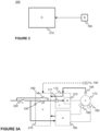
- FIG 1 illustrates schematically an elevator system 1000 according to an example embodiment.
- the elevator system 1000 as disclosed in Figure 1 may comprise an elevator car 110 arranged to be moved or movable in an elevator shaft 120 e.g. along guide rails mounted in the elevator shaft.
- the moving of the elevator car 110 may be implemented by a hoisting rope or belt 130 in connection with a counterweight 140 over a traction sheave 150 or the like.
- the traction sheave 150 belongs to an elevator drive system 160, and to an elevator hoisting machine 165 therein together with an elevator brake composition 180 comprising one or more elevator brakes among other entities.
- the elevator brakes are a type of elevator hoisting machine brakes, but the present invention is applicable also with other types of the elevator brakes, such as with an elevator car brake or a rope brake.
- the elevator hoisting machine brakes are configured to engage against an entity in the elevator hoisting machine 165
- the elevator car brake is configured to engage against the guide rail
- the rope brake is configured to engage against, or grips to, the elevator rope 130.
- the invention is mainly described with respect to the elevator system 1000 comprising the hoisting machine brakes, it is not limited to only such an elevator brake composition 180.
- the elevator hoisting machine 165 comprises an electric motor 170, the traction sheave 150 and the elevator brake composition 180.
- the elevator hoisting machine 165 may be gearless or it may be provided with a gear.
- the electric motor 170 may be controlled with a motor drive 175, such as with a frequency converter, belonging to the elevator drive system 160.
- the control of the electric motor 170 with the motor drive 175 is performed by supplying a variable-amplitude, a variable frequency voltage (VVVF) generated by the motor drive 175 to windings of the electric motor 170 wherein by variating the amplitude and the frequency of the signal a desired control operation may be achieved.
- VVVF variable frequency voltage
- the elevator hoisting machine 165 is configured to operate the traction sheave 150 for moving the elevator car 110 in a known manner.
- the traction sheave 140 may be connected, via a mechanical connection 168, directly or indirectly via the gear to a shaft of the motor 170.
- the traction sheave may also be integrated with the electric motor 170 so that a rotor of the electric motor, such as a rotor of a permanent magnet motor, is formed in the same rotating part with the traction sheave 140.
- the elevator system 1000 may also comprise a machine room or be machine roomless, such as have the motor 170 in the elevator shaft 120.
- the elevator system 1000 may preferably comprise a plurality of landings 10 or landing floors and, for example, landing floor doors and/or openings, between which the elevator car 110 is arranged to be movable during the normal elevator operation, such as to move persons and/or goods between said landings 10.
- the elevator system 1000, and the elevator hoisting machine 165 of the elevator drive system 160 may comprise an elevator brake composition 180 comprising at least one, such as two to four, or even more, elevator brakes configured to prevent a movement of the elevator car 110 in the elevator shaft 120 when such an operation is desired.
- the elevator brake of the brake composition 180 being e.g. the type of the hoisting machine brake(s) may be arranged to engage against the traction sheave 150, or against any other rotating part of the elevator hoisting machine 165, such as against a rotating shaft of the electric motor 170 during the breaking. Therefore, the hoisting machine brake 165 has a brake armature, which moves into brake position to reduce the speed of the elevator car or hold elevator car standstill in elevator shaft.
- the elevator brake composition 180 may be controlled with a brake controller 185 configured to operate the elevator brake composition 180.
- the brake controller 185 may further be in connection and / or integrated with other elements of the elevator 1000, such as an elevator controller 190.
- the brake controller 185 may comprise a control logic as well as an actuator (not shown) for operating the brake composition 180 or at least be in connection with such an actuator.
- the brake controller 185 may be configured to set a control state of the elevator brake composition 180 to either a braking state or to an open state, as is described in more detail in the forthcoming description.
- the elevator controller 190 may also be in communicative connection with other entities, such as with elevator call-giving devices, with the elevator hoisting machine 165, and the motor drive 175, to cause a generation of applicable control signals within the elevator hoisting machine 165 to cause a movement of the elevator car 110 in the shaft 120.
- the elevator controller 190 may also be communicatively connected to the brake controller 185 for causing braking operation when necessary.
- the term "braking operation" refers to a situation wherein brakes are in working order such that, when operated, they provide an adequate braking force to stop and hold elevator car standstill, in accordance with available elevator safety norms.
- the elevator system 1000 may comprise other controllers as well as other components, such as sensors for obtaining measurement data of various events in the elevator system.
- the sensors are denoted with a reference 195 in Figure 1 .
- the elevator car 110 may be provided with a number of sensors 195 for providing measurement data indicative of a movement of the elevator car 110.
- the sensors 195 may also be provided in the elevator hoisting machine 165, or the elevator hoisting machine 165 may comprise entities, such as motor encoder, from which it is possible to obtain data indicative of a movement of respective entities which motor encoder may be considered as a sensor 195 as such.
- one or more sensors 195 may be configured to generated data indicative on an operation of the hoisting machine brakes.
- the sensor(s) 195 may be positioned in the hoisting machine brake so that they may provide data indicative of a position or a movement of a brake armature.
- the sensor(s) 195 may be positioned respectively to generate data indicative of the operation of the elevator brake composition 180. Some sensors 195 may be arranged in the elevator shaft 120 and such sensors 195 may e.g. provide data from which a position the elevator car 110 within the elevator shaft may be derivable. Naturally, the elevator system 1000 may comprise further devices and apparatuses than the ones discussed so far and/or illustrated in Figure 1 . For example, a sensor 195 may be arranged in a diverting pulley of an elevator car or a diverting pulley of an elevator hoisting machine.
- a safety function 177 is implemented to the elevator drive system 160, and specifically to the motor drive 175, which safety function 177 comprises an input for a safety signal receivable from an elevator safety system.
- the safety function 177 is configured at least to selectively control, i.e. to prevent or to enable, a supply of the variable-amplitude, the variable frequency voltage (VVVF) signal to windings of the elevator hoisting machine.
- the decision of the supply of the VVVF voltage signal may be based on a status of the safety signal input to the safety function 177.
- the safety function 177 may be implemented with a hardware solution or a software solution, or any combination of these.
- the hardware solution may e.g. be based on a dedicated circuit board, or on a dedicated logic circuit, for example.
- the present invention relates to an elevator safety system 200 configured to monitor an operation of an elevator system 1000 and to generate measures in response to a detection of a maloperation of the elevator system 1000.
- the operation of the elevator safety system may e.g. be related to a situation that the elevator car 110 remains at the landing zone with the elevator brakes of the elevator brake composition 180 engaged, or travels to a landing, or to any other destination, and is instructed to stop there by controlling the elevator hoisting machine 165, and at some point the elevator brakes of the elevator brake composition 180 are instructed to engage against a counterpart of the elevator, such as the traction sheave 150 or any other rotating entity of the drive system 160 or any other entity corresponding to the type of the elevator brake, and it is assumed that the elevator brakes of the elevator brake composition 180 are capable of holding the elevator car 110 still for the time being.
- the operation may also be related to a situation wherein the elevator safety system commands an emergency stop of an elevator car 110 upon detecting a dangerous situation, such as an overspeed situation or that a deceleration or an acceleration of the elevator is not within allowable limits, or that a safety contact is opened in an elevator safety chain during elevator run.
- a dangerous situation may occur if the elevator brakes of the brake composition 180 are not operational or are not fully operational. For example, when a brake control signal corresponding to a braking state has been issued, but the actual operation of the elevator brake composition 180 does not correspond to the braking state. This may e.g. lead to an unallowed movement, e.g.
- the elevator safety system may be implemented for an elevator system 1000 comprising an elevator drive system 160 having at least an elevator hoisting machine 165 for shifting an elevator car in its travel path and a number of elevator brakes constituting an elevator brake composition 180.
- the elevator brake(s) of the elevator brake composition 180 are configured to engage with an entity through which a movement of an elevator may be limited if the elevator brake composition 180 is operating properly e.g.
- the elevator safety system 200 comprises a safety controller 210 and at least one sensor 195 arranged to measure an operation of the elevator system as is described in the forthcoming description in more detail.
- the safety controller 210 and the at least one sensor 195 are communicatively connected to each other with a wireless communication technology or via a wired connection, such as over a data bus.
- the elevator safety system 200 is communicatively connected to the safety function 177 of the elevator drive system through the input of the safety function 177 to selectively control the supply of the VVVF voltage signal based on a status of a safety signal generated by the safety controller 210.
- the at least one sensor 195 may be any device, or a system, which is suitable for providing data indicative of an operation of the elevator brake composition 180.
- the at least one sensor 195 may be associated to any entity of the elevator system 1000 from which it is possible to obtain data indicative of the operation of the elevator brake composition 180.
- the data may indicate the operation either directly or indirectly wherein the latter may refer to that the data is processed in a predefined manner.
- Such an entity may e.g. be the elevator drive system 160 and the components therein, such as the entities in the elevator hoisting machine 165, but also the elevator car 110, the counterweight 140, or even the elevator rope 130.
- the movement of the elevator may be determined by monitoring of a movement of the elevator car 110 or the counterweight 140 or a diverting pulley with an applicable sensor 195.
- the sensor 195 may be arranged to the elevator car 110 or to the counterweight 140, or even to both.
- the sensor 195 may provide absolute or incremental position data, data indicative of a speed of the respective entity, or data indicative of an acceleration of the respective entity, for example.
- the sensor 195 providing the data indicative of the speed of the respective entity may e.g. be a speedometer whereas the sensor 195 providing the data indicative of the acceleration of the respective entity may e.g. be an accelerometer.
- the data may be obtained from a sensor 195 mounted in the elevator shaft 120.
- the elevator shaft 195 may be provided with a plurality of such sensors 195 e.g. mounted at the landings so that a movement of the elevator car 110 may be detected.
- the detection may e.g. be based on magnetic, optical, or electromagnetic interaction between the sensor and a counterpart mounted e.g. on an outer surface of the elevator car 110 facing the sensor 195 mounted at the landing.
- Sensor may be a camera arranged to observe movement of elevator, in particular movement of a rotating part of an elevator hoisting machine 165.
- the sensor 195 in the elevator shaft 120 may be a radar-based solution for detecting a movement of the elevator, such as the elevator car 110 or the counterweight 140. Such a radar-based solution may be based e.g.
- a sensor 195 may be mounted on a diverting pulley (not shown in Figure 1 ) wherein its possible rotation may be monitored and detected with an applicable sensor 195. The rotation of the diverting pulley directly follows any rotation of the traction sheave 150 if no slipping of the elevator rope is experienced. Still further, any data obtainable from an elevator car 110 encoder as the sensor 195 and / or a door zone sensor 195 may be used as data indicative of a movement of the elevator in at least some embodiments of the invention. Also, a barometer may be used for measuring the movement by detection pressure changes due to the movement.
- the above provided examples are mainly suitable of providing data indicative of the movement of the elevator based on which it is possible to determine aspects on the operation of the elevator brake 180.
- sensors may be e.g. an encoder mounted to elevator car, to a rope pulley or to elevator hoisting machine. Movement may be measured also for example by measuring electromotive force (emf) induced in the windings of the elevator hoisting motor.
- emf electromotive force
- sensors e.g. mounted on the elevator brake composition 180 such as to measure a movement or a position of the armatures of the hoisting machine brake, corresponding data for evaluating the operation of the elevator brake composition 180 may be obtained.
- sensors may be e.g. brake switches or inductive proximity sensors.
- the safety controller 210 of the elevator safety system 200 may be a dedicated apparatus configured to serve the elevator safety system 200 only.
- the operation for the safety controller 210 may be integrated to another entity, such as to another controller, of the elevator system 1000, like as to the elevator controller 190. Its operation may also alternatively be integrated into the motor drive 175 in some implementations.
- similar safety software may run in the DSP (digital signal processing) unit of the motor drive 175, which DSP processing unit also takes care of control of power switching devices of the motor drive 175.
- the operation of the safety controller 210 may also be shared between a plurality of apparatuses as a distributed computing environment wherein the apparatuses may reside locally at a space the elevator system is operating or remotely or at both locations.
- the safety system 200, and especially the safety controller 210 may comprise a safety output for delivering a safety signal to other entities, such as to the input of the safety function 177.
- FIGS 3A , 3B, and 3C illustrate schematically examples of implementing of the present invention.
- the braking of the elevator is arranged so that the elevator brake composition 180 may be used for controlling a rotation of the electric motor 170 e.g. by instructing them to engage against a shaft of the electric motor 170, but as already mentioned the entity referred with 170 in Figures 3A-3C may be any other known entity against which the braking operation may be established, such as a traction sheave of a hoisting machine.
- the brakes of the elevator brake composition 180 may be controlled with a brake controller 185 which may e.g.
- the safety system 200 may also control elevator brakes independent of the motor drive control command.
- the operation of the electric motor 170 may be controlled by the motor drive 175 comprising so-called motor bridge circuit 310 used for modulating the control signal of the electric motor 170 in order to generate a desired VVVF voltage signal in accordance with an input to a safety function 177 of the motor drive 175.
- the examples according to Figures 3A-3C may comprise one or more sensors 195 belonging to the safety system 200.
- the sensors 195 may be associated to any of the entities, as described, and the sensor 195 may e.g.
- motor encoder denoted with a character "E" in the figures
- the data from the motor encoder may be delivered to motor drive 175, and from there e.g. to the safety system 200 as is described in the following.
- a safety controller 210 is arranged to implement the safety operation for the elevator system 1000.
- the safety controller 210 may e.g. be implemented with one or more microprocessors, with a logic circuit and / or a relay logic.
- the safety controller 210 is configured to receive input from a safety chain 320 comprising a number of safety contacts wherein a state of the safety chain 320 may be obtained from a safety relay.
- the safety system 200, and the safety controller 210 may comprise a safety output 330 to provide control to other entities of the elevator system 1000, such as to a safety function 177 of the motor drive 175 by controlling the operation of the motor bridge 310.
- the safety controller 210 may be configured to determine a control state of the elevator brake composition 180 e.g.
- the safety controller 210 may obtain data from at least one sensor 195 to detect if the operation of the elevator brake composition 180 does not correspond to, i.e. deviates from, a braking operation. The detection may e.g. be based on that it is detected that the elevator performs an unallowable movement, such as continues moving even if the control state of the elevator brake composition 180 indicates it is engaged.
- the safety controller 210 may be configured to activate the safety output 330 by controlling a switch followed by a by-pass switch 340 which, in turn, provides voltage to the safety output so activating the motor bridge 310 of the motor drive 175.
- the electric motor 170 may be again controlled, and the motor bridge is instructed to generate such a VVVF voltage signal which causes controlling of a movement of the elevator car 110 with the electric motor 170, which may correspond to limit or brake the movement, and in that manner support the elevator brake composition 180.
- the energy provided for modulating the VVVF voltage signal with the motor bridge may be obtained from mains electricity and/or from an energy regenerated by the rotating electric motor 170, or from any other source called as a primary source.
- the latter is especially advantageous if the provision of the energy from the mains current is prevented by the safety system 200.
- the motor drive 175 may e.g. comprise a relay or a contactor configured for selectively connecting or isolating the motor drive 175 from its primary power supply. A technical effect of this feature is when isolated from primary power supply that the electric motor 170 is prevented to generate acceleration torque which might be dangerous for elevator passengers.
- the safety operation according to an embodiment of the invention is implemented by arranging two separately controllable safety outputs to the safety controller 210 which are referred with 330 and 350 in Figure 3B .
- safety controller 210 may again start determining if the elevator brake 180 is malfunctioning, e.g. if the movement of the elevator, or elevator car 110, continues even if brakes of the elevator brake composition 180 are instructed to be engaged, i.e.
- the control state of the elevator brake composition 180 corresponds to the braking state.
- the safety controller 210 may control the safety output 330 to connect, i.e. to output a voltage therein by closing the relay contact of the safety output 330, which, in turn, re-activates the motor bridge 310 and the limitation of the movement may be performed by controlling the electric motor 170 through an applicable modulation.
- FIG 3C illustrates a still further example of an implementation of the present invention.
- the safety controller 210 or its functionality, is integrated to the motor drive 175 and/or to the brake controller 185.
- the implementation itself may correspond to the one as illustrated in Figure 3B and the functionalities may be shared between the motor drive 175 and/or to the brake controller 185 in a physical sense.
- the safety function may be implemented in a software of a DSP processor, which is configured to generate VVVF control pulses for the power switching device of the motor bridge 310.
- the safety output 330 of the safety controller 210 that is communicatively connected to an input of a safety function 177 of the motor drive 175 as shown in the above described examples may be applied for preventing or enabling a delivery of one or more control pulses to at least one of: control poles of high-side power switching devices of the motor drive 175; low-side power switching devices of the motor drive 175.
- This operation is often referred to as a safety torque off (STO) safety function, in accordance with IEC61508 safety norm.
- High-side switching devices mean e.g. power transistors connected to positive DC link busbar and low-side switching devices mean transistors connected to negative DC link busbar, respectively, of one phase leg of the motor bridge 310.
- the power switching device may correspond to the motor bridge 310 as described in the foregoing description.
- the power switching devices may be a type of one of the following: IGBT-transistors, MOSFET transistors, Silicon carbide, SiC, transistors; Gallium Nitride, GaIN, transistors.
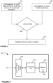
- Figure 4 illustrating schematically a method implemented by an apparatus configured to operate as the safety controller 210 of the elevator safety system 200.
- the at least one brake of the elevator brake composition 180 is controlled by the brake controller 185 by setting the control state of the elevator brake composition 180 to either a braking state or to an open state and the operation of the elevator is monitored at least with the at least one sensor 195 associated to a predefined entity.
- the safety controller 210 is configured to obtain 410 data indicative of the control state of the elevator brake composition 180.
- the control state of the elevator brake composition 180 refers to either that each of the at least one elevator brake 180 of the brake composition are instructed to be engaged or that at least one of the at least one elevator brake of the elevator brake composition 180 is instructed to be not engaged (i.e. it is released) which control states are herein referred as the braking state (when engaged) and the open state (when not engaged), respectively.
- the obtainment of the data 410 performed by the safety controller 210 may comprise a generation of an inquiry to the elevator brake controller 185, or to a plurality of elevator brake controllers 185 if a plurality of elevator brakes of the elevator brake composition 180 are controlled with dedicated brake controllers 185, configured to control the respective brakes and the brake controller 185 may respond to the inquiry by providing an indicator of the current control state of the one or more brakes of the elevator brake composition 180.
- the control state of the elevator brake composition 180 may be obtained by providing access to a control signal of the elevator brake composition 180 for the safety controller 210, such as by measuring a brake coil current of each brake of the elevator brake composition 180 e.g.
- the control signal may e.g. represent a magnetization state of the electromagnets of the elevator brakes in the elevator brake composition 180 either directly or indirectly.
- the brakes of the elevator brake composition 180 may be equipped with applicable brake sensors, such as brake switches, from which a measurement data is obtained by the safety controller 210 either directly or indirectly for determining the control states.
- the hoisting machine comprises a plurality of elevator brakes of the elevator brake composition 180 which are individually controlled, the control states of each of the individual elevator brakes are determined in accordance with the present invention.
- the safety controller 210 may perform a detection between the braking state and the open state of each brake of the elevator brake composition 180. For example, if the elevator brake composition 180 (meaning all the elevator brakes in the elevator brake composition) is controlled to be on the braking state or not. Alternatively or additionally, the control states of the elevator brake composition 180 may be obtained by reading the control states from the brake control logic.
- the safety controller 210 is configured to obtain 420 data from at least one sensor 195.
- the obtained data from the at least one sensor 195 is such that it is indicative of an operation of the elevator brake 180 either directly or indirectly.
- the data shall be such that in indicates, or it is derivable from the data, if the elevator brake 180 composition provides a braking operation, i.e. brakes, at a predefined braking force, or not.
- the predefined braking force may be an elevator dependent and follow specifications set for the elevators.
- the obtainment 410 of the data indicative of the control state of the elevator brake composition 180 and the obtainment 420 of the data from the at least one sensor 195 may advantageously be arranged to occur concurrently and/or continuously to enable a reliable detection in step 430 of the method.
- detections based on the pieces of data may be performed. First, it is detected if the control state of the elevator brake composition 180 corresponds to the braking state. Second, it is detected, based on the data obtained from the at least one sensor 195, if the operation of the elevator brake composition 180 does not correspond to a braking operation, i.e. deviates from the braking operation, with adequate braking force.
- a safety signal may be generated 440 to enable a supply of the VVVF voltage signal to the electric motor 170, because the state of the elevator may cause risks to users of the elevator system e.g. at landings where passengers may enter and exit the elevator car 110, but for some reason the elevator brake composition 180 does not maintain the elevator stationary.
- the elevator hoisting machine 165 is caused to generate a torque for supporting the operation, or non-operation, of the elevator brake composition 180.
- This may e.g. allow to limit, or to brake, the movement of the elevator.
- the VVVF voltage signal may be delivered to the motor bridge 310 of the motor drive 175 in the elevator hoisting machine 165 to cause the electric motor 170 to generate the torque to the traction sheave 150, or any other applicable entity, to brake the movement of the elevator.
- the safety controller 210 may generate the safety signal to the motor drive 175 e.g. having its own controller for defining and generating a desired control for the electric motor 170.
- the motor drive 175 may receive data indicative of a necessary braking torque from the safety controller 210.
- the data may define one or more parameters relating to the movement of the elevator, i.e. the monitored entity, or the part of the elevator system.
- the parameter may e.g. represent a speed of the respective entity, or any respective parameter, based on which the controller may define a necessary torque for the motor 170 to brake the movement, and make e.g.
- a drifting of the elevator car 110 having e.g. heavy load downwards from the landing e.g. during a course of loading the elevator car 110 may be an example of the situation in which the present invention is applied for limiting the movement by generating the braking torque against the gravity with the elevator hoisting machine.
- the generation of the torque for limiting the movement of the elevator may also covers a generation of the torques which causes returning of the elevator car 110 at a desired location, such as to the landing 10, which may correspond to a relevelling operation of the elevator car 110.
- the safety controller 210 of the elevator safety system 200 may be configured to generate an indication to users of the elevator system, such as to the passengers of the elevator car 110, for requesting the users to exit from the elevator car 110 in response to the torque is generated. This may occur with output devices suitable for providing visual or audible, or any other applicable, indications.
- the generation of the indication may be triggered when the elevator car 110 is detected to reside at a door zone of the landing. In response to that the passengers have exited from the elevator car 110 the elevator system 1000 may be set to service mode and its use is prevented.
- This may include, but is not limited to, shifting of the empty elevator car to a safety location, which may e.g. correspond to a space above a topmost door zone so that there is no access to the elevator car 110.
- the safety controller 210 is configured to cause safety shutdown of the elevator upon arrival of elevator car 110 to a shaft 120 end terminal.
- the safety controller 210 may be configured to control SBC (safe brake control) function of the elevator brake composition 180 as well. This means that power supply of brake coils of the elevator brake composition 180 may be allowed or interrupted based on operational state of the elevator safety controller 210. Operation state of the safety controller may be determined based on status of elevator safety chain. Safety chain may be configured such that power supply to brake coils will be interrupted in case an operational anomaly, such as undesired movement of elevator car 110 is detected or opening of a safety contact is detected based on the method in accordance with the present invention. In accordance with the present invention, the safety controller 210 may be configured to, independently of a state of the safety signal, generate the SBC signal for engaging the elevator brake composition 180.
- SBC safety brake control
- the entity arranged to perform the method is a safety controller 210.
- An example of an apparatus configurable to take a role of the safety controller 210 is schematically illustrated in Figure 5 .
- the apparatus comprises a processor 510 and a memory 520.
- the memory 520 may store data, such pieces of data as described but also computer program code 525 causing the safety operation in the described manner.
- the apparatus may further comprise a communication interface, such as a wireless communication interface or a communication interface for wired communication, or both.
- the communication interface may thus comprise one or more modems, antennas, and any other hardware and software for enabling an execution of the communication e.g. under control of the processor 510.
- I/O (input/output) components may be arranged, together with the processor 510 and a portion of the computer program code 525, to provide a user interface for receiving input from a user, such as from a technician, and/or providing output to the user of the apparatus when necessary.
- the user I/O components may include user input means, such as one or more keys or buttons, a keyboard, a touchscreen, or a touchpad, etc.
- the user I/O components may include output means, such as a loudspeaker, a display, or a touchscreen.
- the components of the apparatus may be communicatively connected to each other via data bus that enables transfer of data and control information between the components.
- the memory 520 and a portion of the computer program code 525 stored therein may further be arranged, with the processor 510, to cause the apparatus to perform at least a portion of a method for managing the maintenance as is described herein.
- the processor 510 may be configured to read from and write to the memory 520.
- the processor 510 is depicted as a respective single component, it may be implemented as respective one or more separate processing components.
- the memory 520 is depicted as a respective single component, it may be implemented as respective one or more separate components, some or all of which may be integrated/removable and/or may provide permanent / semi-permanent / dynamic / cached storage.
- the computer program code 525 may comprise computer-executable instructions that implement functions that correspond to steps of the method when the computer program code 525 is loaded into the processor 510 of the safety controller 210 and executed therein.
- the computer program code 525 may include a computer program consisting of one or more sequences of one or more instructions.
- the processor 510 is able to load and execute the computer program by reading the one or more sequences of one or more instructions included therein from the memory 520.
- the one or more sequences of one or more instructions may be configured to, when executed by the processor 510, cause the apparatus to perform a method as explicitly described in the description herein.
- the apparatus may comprise at least one processor 510 and at least one memory 520 including the computer program code 525 for one or more programs, the at least one memory 520 and the computer program code 525 configured to, with the at least one processor 510, cause the apparatus to perform the method.
- the computer program code 525 may be provided e.g. a computer program product comprising at least one computer-readable non-transitory medium having the computer program code 525 stored thereon, which computer program code 525, when executed by the processor 510 causes the apparatus to perform the method.
- the computer-readable non-transitory medium may comprise a memory device or a record medium such as a CD-ROM, a DVD, a Blu-ray disc, or another article of manufacture that tangibly embodies the computer program.
- the computer program may be provided as a signal configured to reliably transfer the computer program.
- the computer program code 525 may comprise a proprietary application, such as computer program code for causing an execution of the method in the manner as described in the description herein.
- the entity performing the method may also be implemented with a plurality of apparatuses, such as the one schematically illustrated in Figure 5 , as a distributed computing environment.
- one of the apparatuses may be communicatively connected with other apparatuses, and e.g. share the data of the method, to cause another apparatus to perform at least one portion of the method.
- the method performed in the distributed computing environment generates the safety operation in the elevator system 1000 in the manner as described.
- an elevator system 1000 comprising an elevator car 110, a counterweight 140, and an elevator drive system 160.
- the elevator drive system comprises an elevator hoisting machine 165 and elevator brake composition 180.
- the elevator system 1000 may comprise hoisting ropes 130 arranged to run between the elevator car 110 and the counterweight 140 via a traction sheave 150 of the elevator hoisting machine 165 and an elevator safety system 200 as described in the foregoing description.
- the elevator hoisting machine 165 may comprise an electric motor 170 being a type of a permanent magnet motor and a motor drive 175 for controlling the electric motor 170.
- the elevator system 1000 in accordance with the present invention may correspond to one as schematically illustrated in Figure 1 wherein the elevator safety system 200 is arranged to.
Landscapes
- Maintenance And Inspection Apparatuses For Elevators (AREA)
Claims (15)
- Système de sécurité d'ascenseur (200) pour un système d'ascenseur (1000) comprenant un système d'entraînement d'ascenseur (160), le système d'entraînement d'ascenseur (160) comprenant :une machine de levage d'ascenseur (165) comprenant un moteur électrique (170) ;une composition de frein d'ascenseur (180) comprenant au moins un frein d'ascenseur ;un dispositif de commande de frein (185) configuré pour définir un état de commande de la composition de frein d'ascenseur (180) sur l'un de : un état de freinage ; un état ouvert ;un entraînement de moteur (175) configuré pour fournir un signal de tension d'amplitude variable et de fréquence variable, VVVF, à des enroulements du moteur électrique (170) de la machine de levage d'ascenseur (165) ;une fonction de sécurité (177) comprenant une entrée pour un signal de sécurité, la fonction de sécurité (177) étant configurée pour empêcher ou permettre de manière sélective la fourniture du signal de tension VVVF sur la base d'un état du signal de sécurité ;le système de sécurité d'ascenseur (200) comprenant :au moins un capteur (195) configuré pour générer des données indicatives d'un fonctionnement de la composition de frein d'ascenseur (180) ;
etun dispositif de commande de sécurité (210) configuré pour :obtenir (410) des données indicatives de l'état de commande de la composition de frein d'ascenseur (180) en identifiant si le dispositif de commande de frein (185) ordonne que l'état de commande de la composition de frein d'ascenseur (180) corresponde à l'état de freinage,obtenir (420) des données en provenance de l'au moins un capteur (195),
etgénérer (440) le signal de sécurité pour permettre une fourniture du signal de tension VVVF en réponse à :une détection (430) du fait que l'état de commande de la composition de frein d'ascenseur (180) correspond à l'état de freinage,
etune détection (430), sur la base des données obtenues en provenance de l'au moins un capteur (195), du fait que le fonctionnement de la composition de frein d'ascenseur (180) ne correspond pas à une opération de freinage,dans lequel l'au moins un capteur (195) est configuré pour générer des données indicatives d'un mouvement d'un ascenseur comme données indicatives du fonctionnement de la composition de frein d'ascenseur (180), etle dispositif de commande de sécurité (210) est configuré pour détecter que le fonctionnement de la composition de frein d'ascenseur (180) ne correspond pas à l'opération de freinage en réponse à une détection d'un mouvement non admissible de l'ascenseur,
oudans lequel l'au moins un capteur (195) est configuré pour générer des données indicatives d'un mouvement ou d'une position de chaque armature de la composition de frein d'ascenseur (180) comme données indicatives du fonctionnement de la composition de frein d'ascenseur (180), etle dispositif de commande de sécurité (210) est configuré pour détecter que le fonctionnement de la composition de frein d'ascenseur (180) ne correspond pas à l'opération de freinage sur la base de données indicatives de la position ou du mouvement de chaque armature ;et dans lequel le dispositif de commande de sécurité (210) est configuré pour amener l'entraînement de moteur (175) à générer un couple pour limiter ou freiner un mouvement de la cabine d'ascenseur (110) en réponse à la génération du signal de sécurité. - Système de sécurité (200) selon la revendication 1, dans lequel le dispositif de commande de sécurité (210) est configuré pour générer un signal de commande de freinage de sécurité, SBC, pour activer la composition de frein d'ascenseur (180).
- Système de sécurité (200) selon l'une quelconque des revendications précédentes, dans lequel l'au moins un capteur (195) est adapté pour générer des données indicatives du mouvement d'au moins l'un de ce qui suit : une machine de levage d'ascenseur (165) ; une poulie de renvoi d'un ascenseur.
- Système de sécurité (200) selon l'une quelconque des revendications précédentes, dans lequel le dispositif de commande de sécurité (210) comprend une sortie de sécurité (330) pour le signal de sécurité.
- Système de sécurité (200) selon la revendication 4, dans lequel la sortie de sécurité (330) du dispositif de commande de sécurité (210) est reliée en communication à une entrée d'une fonction de sécurité (177) de l'entraînement de moteur (175), la sortie de sécurité (330) est applicable pour empêcher ou permettre une fourniture d'une ou plusieurs impulsions de commande à au moins l'un de ce qui suit : des pôles de commande de dispositifs de commutation de puissance côté haut de l'entraînement de moteur (175) ; des dispositifs de commutation de puissance côté bas de l'entraînement de moteur (175).
- Système de sécurité (200) selon l'une quelconque des revendications précédentes, dans lequel le dispositif de commande de sécurité (210) est intégré dans l'entraînement de moteur (175).
- Système de sécurité (200) selon l'une quelconque des revendications précédentes 2 à 6, dans lequel le dispositif de commande de sécurité (210) est configuré pour détecter le mouvement non admissible en détectant au moins l'un de ce qui suit : la cabine d'ascenseur (110) se déplace avec des portes ouvertes au niveau de la zone d'atterrissage ; une vitesse de la cabine d'ascenseur (110) dépasse une limite prédéfinie ; une décélération ou une accélération d'ascenseur s'écarte de limites admissibles ; un contact de sécurité est ouvert dans une chaîne de sécurité d'ascenseur pendant un trajet d'ascenseur.
- Procédé de fonctionnement de sécurité d'un système d'ascenseur (1000), le système d'ascenseur (1000) comprenant un système d'entraînement d'ascenseur (160) comprenant :une machine de levage d'ascenseur (165) comprenant un moteur électrique (170) ;une composition de frein d'ascenseur (180) comprenant au moins un frein d'ascenseur ;un dispositif de commande de frein (185) configuré pour définir un état de commande de la composition de frein d'ascenseur (180) sur l'un de : un état de freinage ; un état ouvert ;un entraînement de moteur (175) configuré pour fournir un signal de tension d'amplitude variable et de fréquence variable, VVVF, à des enroulements du moteur électrique (170) de la machine de levage d'ascenseur (165) ;une fonction de sécurité (177) comprenant une entrée pour un signal de sécurité, la fonction de sécurité (177) étant configurée pour empêcher ou permettre de manière sélective la fourniture du signal de tension VVVF sur la base d'un état du signal de sécurité ;le procédé, réalisé par un dispositif de commande de sécurité (210) d'un système de sécurité d'ascenseur (200), comprend :l'obtention (410) de données indicatives de l'état de commande de la composition de frein d'ascenseur (180) en identifiant si le dispositif de commande de frein (185) ordonne que l'état de commande de la composition de frein d'ascenseur (180) corresponde à l'état de freinage,l'obtention (420) de données en provenance de l'au moins un capteur (195), etla génération (440) du signal de sécurité pour permettre une fourniture du signal de tension VVVF en réponse à :une détection (430) du fait que l'état de commande de la composition de frein d'ascenseur (180) correspond à l'état de freinage,
etune détection (430), sur la base des données obtenues en provenance de l'au moins un capteur (195), du fait que le fonctionnement de la composition de frein d'ascenseur (180) ne correspond pas à une opération de freinage,dans lequel l'au moins un capteur (195) est configuré pour générer des données indicatives d'un mouvement d'un ascenseur comme données indicatives du fonctionnement de la composition de frein d'ascenseur (180), etle dispositif de commande de sécurité (210) est configuré pour détecter que le fonctionnement de la composition de frein d'ascenseur (180) ne correspond pas à l'opération de freinage en réponse à une détection d'un mouvement non admissible de l'ascenseur,
oudans lequel l'au moins un capteur (195) est configuré pour générer des données indicatives d'un mouvement ou d'une position de chaque armature de la composition de frein d'ascenseur (180) comme données indicatives du fonctionnement de la composition de frein d'ascenseur (180), etle dispositif de commande de sécurité (210) est configuré pour détecter que le fonctionnement de la composition de frein d'ascenseur (180) ne correspond pas à l'opération de freinage sur la base de données indicatives de la position ou du mouvement de chaque armature ;et le fait d'amener l'entraînement de moteur (175) à générer un couple pour limiter ou freiner un mouvement de la cabine d'ascenseur (110) en réponse à la génération du signal de sécurité. - Procédé selon la revendication 8, dans lequel un signal de commande de freinage de sécurité, SBC, est généré, par le dispositif de commande de sécurité (210), pour activer la composition de frein d'ascenseur (180).
- Procédé selon la revendication 8 ou la revendication 9, dans lequel des données indicatives du mouvement d'au moins l'un de ce qui suit : une machine de levage d'ascenseur (165) ; une poulie de renvoi d'un ascenseur sont générées par l'au moins un capteur (195).
- Procédé selon l'une quelconque des revendications précédentes 8 à 10, dans lequel une sortie de sécurité (330) du dispositif de commande de sécurité (210) est appliquée pour empêcher ou permettre une fourniture d'une ou plusieurs impulsions de commande à au moins l'un de ce qui suit : des pôles de commande de dispositifs de commutation de puissance côté haut de l'entraînement de moteur (175) ; des dispositifs de commutation de puissance côté bas de l'entraînement de moteur (175).
- Procédé selon l'une quelconque des revendications précédentes 8 à 11, dans lequel le mouvement non admissible est détecté, par le dispositif de commande de sécurité (210), en détectant au moins l'un de ce qui suit : la cabine d'ascenseur (110) se déplace avec des portes ouvertes au niveau de la zone d'atterrissage ; une vitesse de la cabine d'ascenseur (110) dépasse une limite prédéfinie ; une décélération ou une accélération d'ascenseur s'écarte de limites admissibles ; un contact de sécurité est ouvert dans une chaîne de sécurité d'ascenseur pendant le trajet d'ascenseur.
- Programme informatique comprenant du code de programme lisible par ordinateur configuré pour entraîner la réalisation des étapes de procédé du dispositif de commande de sécurité (210) selon la revendication 8 lorsque le code de programme lisible par ordinateur est exécuté sur le dispositif de commande de sécurité (210).
- Système d'ascenseur (1000) comprenant :une cabine d'ascenseur (110),un système de sécurité d'ascenseur (200) selon l'une quelconque des revendications 1 à 7.
- Système d'ascenseur (1000) selon la revendication 14, dans lequel l'entraînement de moteur (175) comprend un relais ou un contacteur configuré pour relier ou isoler de manière sélective l'entraînement de moteur et sa source d'alimentation électrique principale.
Applications Claiming Priority (1)
| Application Number | Priority Date | Filing Date | Title |
|---|---|---|---|
| PCT/EP2021/069329 WO2023284938A1 (fr) | 2021-07-12 | 2021-07-12 | Solution de sécurité pour ascenseurs |
Publications (2)
| Publication Number | Publication Date |
|---|---|
| EP4370462A1 EP4370462A1 (fr) | 2024-05-22 |
| EP4370462B1 true EP4370462B1 (fr) | 2025-03-19 |
Family
ID=76943011
Family Applications (1)
| Application Number | Title | Priority Date | Filing Date |
|---|---|---|---|
| EP21742387.0A Active EP4370462B1 (fr) | 2021-07-12 | 2021-07-12 | Solution de sécurité pour ascenseurs |
Country Status (3)
| Country | Link |
|---|---|
| EP (1) | EP4370462B1 (fr) |
| CN (1) | CN116601100A (fr) |
| WO (1) | WO2023284938A1 (fr) |
Family Cites Families (14)
| Publication number | Priority date | Publication date | Assignee | Title |
|---|---|---|---|---|
| CN1146421A (zh) * | 1996-02-10 | 1997-04-02 | 中国科学院合肥智能机械研究所 | 无介面接口的电梯语音报站方法及装置 |
| CN1144752C (zh) * | 1999-03-16 | 2004-04-07 | 西安高能电机控制技术有限责任公司 | 直流无刷电梯拖动控制系统 |
| KR100874571B1 (ko) * | 2003-10-07 | 2008-12-16 | 오티스 엘리베이터 컴파니 | 전기 엘리베이터 구조 시스템 |
| CN101077747A (zh) * | 2006-05-22 | 2007-11-28 | 东芝电梯株式会社 | 电梯控制柜 |
| CN101259927B (zh) * | 2007-03-05 | 2012-05-23 | 铃木电梯(中国)有限公司 | 具有主副电脑板的电梯控制系统 |
| EP2315717B1 (fr) * | 2008-08-18 | 2013-07-10 | Inventio AG | Procédé de surveillance d'un système de frein dans une installation d'ascenseur et moniteur de frein correspondant pour une installation d'ascenseur |
| FI123506B (fi) * | 2012-05-31 | 2013-06-14 | Kone Corp | Hissin käyttölaite sekä hissin turvajärjestely |
| FI125316B (fi) * | 2013-09-10 | 2015-08-31 | Kone Corp | Menetelmä hätäpysäytyksen suorittamiseksi sekä hissin turvajärjestely |
| EP2848568B1 (fr) | 2013-09-17 | 2022-07-20 | KONE Corporation | Procédé et ascenseur pour arrêter une cabine d'ascenseur au moyen d'entraînement de l'ascenseur |
| CN105692400A (zh) * | 2016-04-19 | 2016-06-22 | 苏州莱茵电梯股份有限公司 | 一种单柱悬臂式家庭电梯 |
| EP3239086B1 (fr) * | 2016-04-28 | 2022-06-01 | KONE Corporation | Solution pour contrôler un frein d'ascenseur |
| CN109305615A (zh) * | 2017-07-27 | 2019-02-05 | 奥的斯电梯公司 | 电梯制动器的制动力矩检测 |
| EP3556704B1 (fr) * | 2018-04-16 | 2023-08-30 | KONE Corporation | Frein d'ascenseur |
| CN113748076B (zh) * | 2019-05-07 | 2023-07-11 | 因温特奥股份公司 | 电梯设备的驱动装置 |
-
2021
- 2021-07-12 CN CN202180078029.XA patent/CN116601100A/zh active Pending
- 2021-07-12 EP EP21742387.0A patent/EP4370462B1/fr active Active
- 2021-07-12 WO PCT/EP2021/069329 patent/WO2023284938A1/fr not_active Ceased
Also Published As
| Publication number | Publication date |
|---|---|
| EP4370462A1 (fr) | 2024-05-22 |
| CN116601100A (zh) | 2023-08-15 |
| WO2023284938A1 (fr) | 2023-01-19 |
Similar Documents
| Publication | Publication Date | Title |
|---|---|---|
| US12258241B2 (en) | Elevator including safety monitoring that prevents excessive deceleration during slowdown failure | |
| US8167094B2 (en) | Elevator apparatus | |
| CN101468769B (zh) | 电梯的开门行驶防止系统 | |
| EP2448854B2 (fr) | Phase de départ à entraînement par gravité dans une opération de secours pour ascenseur à alimentation limitée | |
| US9434575B2 (en) | Method and device for a safe emergency stop of an elevator | |
| EP3287404B1 (fr) | Ascenseur comprennent un dispositif de freinage et une commande électrique | |
| US9604819B2 (en) | Elevator monitoring arrangement configured to monitor operation of a safety device of an elevator, a controller and method for performing same | |
| CN112678637B (zh) | 用于监视电梯的制动拖曳的方法 | |
| EP4370462B1 (fr) | Solution de sécurité pour ascenseurs | |
| CN106966248B (zh) | 轿厢意外移动保护装置和方法 | |
| JP4537043B2 (ja) | エレベーターのブレーキ制御装置 | |
| EP3753891A1 (fr) | Dispositif de freinage d'urgence | |
| KR20120014003A (ko) | 엘리베이터의 제어 장치 | |
| EP2436635A1 (fr) | Dispositif élévateur | |
| HK40098717A (zh) | 用於电梯的安全方案 | |
| WO2018008220A1 (fr) | Ascenseur | |
| WO2022228657A1 (fr) | Solution de sécurité pour ascenseurs | |
| HK40046326A (en) | A method for monitoring brake dragging of an elevator | |
| HK40046326B (zh) | 用於监视电梯的制动拖曳的方法 | |
| HK40022610B (en) | Elevator |
Legal Events
| Date | Code | Title | Description |
|---|---|---|---|
| STAA | Information on the status of an ep patent application or granted ep patent |
Free format text: STATUS: UNKNOWN |
|
| STAA | Information on the status of an ep patent application or granted ep patent |
Free format text: STATUS: THE INTERNATIONAL PUBLICATION HAS BEEN MADE |
|
| PUAI | Public reference made under article 153(3) epc to a published international application that has entered the european phase |
Free format text: ORIGINAL CODE: 0009012 |
|
| STAA | Information on the status of an ep patent application or granted ep patent |
Free format text: STATUS: REQUEST FOR EXAMINATION WAS MADE |
|
| 17P | Request for examination filed |
Effective date: 20240108 |
|
| AK | Designated contracting states |
Kind code of ref document: A1 Designated state(s): AL AT BE BG CH CY CZ DE DK EE ES FI FR GB GR HR HU IE IS IT LI LT LU LV MC MK MT NL NO PL PT RO RS SE SI SK SM TR |
|
| P01 | Opt-out of the competence of the unified patent court (upc) registered |
Free format text: CASE NUMBER: APP_40172/2024 Effective date: 20240705 |
|
| GRAP | Despatch of communication of intention to grant a patent |
Free format text: ORIGINAL CODE: EPIDOSNIGR1 |
|
| STAA | Information on the status of an ep patent application or granted ep patent |
Free format text: STATUS: GRANT OF PATENT IS INTENDED |
|
| DAV | Request for validation of the european patent (deleted) | ||
| DAX | Request for extension of the european patent (deleted) | ||
| INTG | Intention to grant announced |
Effective date: 20241008 |
|
| GRAS | Grant fee paid |
Free format text: ORIGINAL CODE: EPIDOSNIGR3 |
|
| GRAA | (expected) grant |
Free format text: ORIGINAL CODE: 0009210 |
|
| STAA | Information on the status of an ep patent application or granted ep patent |
Free format text: STATUS: THE PATENT HAS BEEN GRANTED |
|
| AK | Designated contracting states |
Kind code of ref document: B1 Designated state(s): AL AT BE BG CH CY CZ DE DK EE ES FI FR GB GR HR HU IE IS IT LI LT LU LV MC MK MT NL NO PL PT RO RS SE SI SK SM TR |
|
| REG | Reference to a national code |
Ref country code: GB Ref legal event code: FG4D |
|
| REG | Reference to a national code |
Ref country code: CH Ref legal event code: EP |
|
| REG | Reference to a national code |
Ref country code: DE Ref legal event code: R096 Ref document number: 602021027837 Country of ref document: DE |
|
| REG | Reference to a national code |
Ref country code: IE Ref legal event code: FG4D |
|
| PG25 | Lapsed in a contracting state [announced via postgrant information from national office to epo] |
Ref country code: RS Free format text: LAPSE BECAUSE OF FAILURE TO SUBMIT A TRANSLATION OF THE DESCRIPTION OR TO PAY THE FEE WITHIN THE PRESCRIBED TIME-LIMIT Effective date: 20250619 |
|
| PG25 | Lapsed in a contracting state [announced via postgrant information from national office to epo] |
Ref country code: FI Free format text: LAPSE BECAUSE OF FAILURE TO SUBMIT A TRANSLATION OF THE DESCRIPTION OR TO PAY THE FEE WITHIN THE PRESCRIBED TIME-LIMIT Effective date: 20250319 |
|
| REG | Reference to a national code |
Ref country code: LT Ref legal event code: MG9D |
|
| PG25 | Lapsed in a contracting state [announced via postgrant information from national office to epo] |
Ref country code: NO Free format text: LAPSE BECAUSE OF FAILURE TO SUBMIT A TRANSLATION OF THE DESCRIPTION OR TO PAY THE FEE WITHIN THE PRESCRIBED TIME-LIMIT Effective date: 20250619 |
|
| PG25 | Lapsed in a contracting state [announced via postgrant information from national office to epo] |
Ref country code: HR Free format text: LAPSE BECAUSE OF FAILURE TO SUBMIT A TRANSLATION OF THE DESCRIPTION OR TO PAY THE FEE WITHIN THE PRESCRIBED TIME-LIMIT Effective date: 20250319 |
|
| PG25 | Lapsed in a contracting state [announced via postgrant information from national office to epo] |
Ref country code: LV Free format text: LAPSE BECAUSE OF FAILURE TO SUBMIT A TRANSLATION OF THE DESCRIPTION OR TO PAY THE FEE WITHIN THE PRESCRIBED TIME-LIMIT Effective date: 20250319 |
|
| PG25 | Lapsed in a contracting state [announced via postgrant information from national office to epo] |
Ref country code: BG Free format text: LAPSE BECAUSE OF FAILURE TO SUBMIT A TRANSLATION OF THE DESCRIPTION OR TO PAY THE FEE WITHIN THE PRESCRIBED TIME-LIMIT Effective date: 20250319 Ref country code: GR Free format text: LAPSE BECAUSE OF FAILURE TO SUBMIT A TRANSLATION OF THE DESCRIPTION OR TO PAY THE FEE WITHIN THE PRESCRIBED TIME-LIMIT Effective date: 20250620 |
|
| REG | Reference to a national code |
Ref country code: NL Ref legal event code: MP Effective date: 20250319 |
|
| PG25 | Lapsed in a contracting state [announced via postgrant information from national office to epo] |
Ref country code: NL Free format text: LAPSE BECAUSE OF FAILURE TO SUBMIT A TRANSLATION OF THE DESCRIPTION OR TO PAY THE FEE WITHIN THE PRESCRIBED TIME-LIMIT Effective date: 20250319 |
|
| PG25 | Lapsed in a contracting state [announced via postgrant information from national office to epo] |
Ref country code: SE Free format text: LAPSE BECAUSE OF FAILURE TO SUBMIT A TRANSLATION OF THE DESCRIPTION OR TO PAY THE FEE WITHIN THE PRESCRIBED TIME-LIMIT Effective date: 20250319 |
|
| PG25 | Lapsed in a contracting state [announced via postgrant information from national office to epo] |
Ref country code: SM Free format text: LAPSE BECAUSE OF FAILURE TO SUBMIT A TRANSLATION OF THE DESCRIPTION OR TO PAY THE FEE WITHIN THE PRESCRIBED TIME-LIMIT Effective date: 20250319 |
|
| PG25 | Lapsed in a contracting state [announced via postgrant information from national office to epo] |
Ref country code: ES Free format text: LAPSE BECAUSE OF FAILURE TO SUBMIT A TRANSLATION OF THE DESCRIPTION OR TO PAY THE FEE WITHIN THE PRESCRIBED TIME-LIMIT Effective date: 20250319 Ref country code: PT Free format text: LAPSE BECAUSE OF FAILURE TO SUBMIT A TRANSLATION OF THE DESCRIPTION OR TO PAY THE FEE WITHIN THE PRESCRIBED TIME-LIMIT Effective date: 20250721 |
|
| PGFP | Annual fee paid to national office [announced via postgrant information from national office to epo] |
Ref country code: DE Payment date: 20250722 Year of fee payment: 5 |
|
| PG25 | Lapsed in a contracting state [announced via postgrant information from national office to epo] |
Ref country code: PL Free format text: LAPSE BECAUSE OF FAILURE TO SUBMIT A TRANSLATION OF THE DESCRIPTION OR TO PAY THE FEE WITHIN THE PRESCRIBED TIME-LIMIT Effective date: 20250319 Ref country code: IT Free format text: LAPSE BECAUSE OF FAILURE TO SUBMIT A TRANSLATION OF THE DESCRIPTION OR TO PAY THE FEE WITHIN THE PRESCRIBED TIME-LIMIT Effective date: 20250319 |
|
| PG25 | Lapsed in a contracting state [announced via postgrant information from national office to epo] |
Ref country code: AT Free format text: LAPSE BECAUSE OF FAILURE TO SUBMIT A TRANSLATION OF THE DESCRIPTION OR TO PAY THE FEE WITHIN THE PRESCRIBED TIME-LIMIT Effective date: 20250319 |
|
| PGFP | Annual fee paid to national office [announced via postgrant information from national office to epo] |
Ref country code: FR Payment date: 20250725 Year of fee payment: 5 |
|
| PG25 | Lapsed in a contracting state [announced via postgrant information from national office to epo] |
Ref country code: EE Free format text: LAPSE BECAUSE OF FAILURE TO SUBMIT A TRANSLATION OF THE DESCRIPTION OR TO PAY THE FEE WITHIN THE PRESCRIBED TIME-LIMIT Effective date: 20250319 Ref country code: CZ Free format text: LAPSE BECAUSE OF FAILURE TO SUBMIT A TRANSLATION OF THE DESCRIPTION OR TO PAY THE FEE WITHIN THE PRESCRIBED TIME-LIMIT Effective date: 20250319 |
|
| PG25 | Lapsed in a contracting state [announced via postgrant information from national office to epo] |
Ref country code: RO Free format text: LAPSE BECAUSE OF FAILURE TO SUBMIT A TRANSLATION OF THE DESCRIPTION OR TO PAY THE FEE WITHIN THE PRESCRIBED TIME-LIMIT Effective date: 20250319 |
|
| PG25 | Lapsed in a contracting state [announced via postgrant information from national office to epo] |
Ref country code: SK Free format text: LAPSE BECAUSE OF FAILURE TO SUBMIT A TRANSLATION OF THE DESCRIPTION OR TO PAY THE FEE WITHIN THE PRESCRIBED TIME-LIMIT Effective date: 20250319 |
|
| PG25 | Lapsed in a contracting state [announced via postgrant information from national office to epo] |
Ref country code: IS Free format text: LAPSE BECAUSE OF FAILURE TO SUBMIT A TRANSLATION OF THE DESCRIPTION OR TO PAY THE FEE WITHIN THE PRESCRIBED TIME-LIMIT Effective date: 20250719 |
|
| REG | Reference to a national code |
Ref country code: DE Ref legal event code: R097 Ref document number: 602021027837 Country of ref document: DE |
|
| PG25 | Lapsed in a contracting state [announced via postgrant information from national office to epo] |
Ref country code: DK Free format text: LAPSE BECAUSE OF FAILURE TO SUBMIT A TRANSLATION OF THE DESCRIPTION OR TO PAY THE FEE WITHIN THE PRESCRIBED TIME-LIMIT Effective date: 20250319 |
|
| PLBE | No opposition filed within time limit |
Free format text: ORIGINAL CODE: 0009261 |
|
| STAA | Information on the status of an ep patent application or granted ep patent |
Free format text: STATUS: NO OPPOSITION FILED WITHIN TIME LIMIT |
|
| REG | Reference to a national code |
Ref country code: CH Ref legal event code: L10 Free format text: ST27 STATUS EVENT CODE: U-0-0-L10-L00 (AS PROVIDED BY THE NATIONAL OFFICE) Effective date: 20260128 |
|
| REG | Reference to a national code |
Ref country code: CH Ref legal event code: H13 Free format text: ST27 STATUS EVENT CODE: U-0-0-H10-H13 (AS PROVIDED BY THE NATIONAL OFFICE) Effective date: 20260224 |
|
| 26N | No opposition filed |
Effective date: 20251222 |
|
| PG25 | Lapsed in a contracting state [announced via postgrant information from national office to epo] |
Ref country code: LU Free format text: LAPSE BECAUSE OF NON-PAYMENT OF DUE FEES Effective date: 20250712 |
|
| GBPC | Gb: european patent ceased through non-payment of renewal fee |
Effective date: 20250712 |
|
| REG | Reference to a national code |
Ref country code: BE Ref legal event code: MM Effective date: 20250731 |
|
| PG25 | Lapsed in a contracting state [announced via postgrant information from national office to epo] |
Ref country code: GB Free format text: LAPSE BECAUSE OF NON-PAYMENT OF DUE FEES Effective date: 20250712 |
|
| PG25 | Lapsed in a contracting state [announced via postgrant information from national office to epo] |
Ref country code: BE Free format text: LAPSE BECAUSE OF NON-PAYMENT OF DUE FEES Effective date: 20250731 |
|
| PG25 | Lapsed in a contracting state [announced via postgrant information from national office to epo] |
Ref country code: CH Free format text: LAPSE BECAUSE OF NON-PAYMENT OF DUE FEES Effective date: 20250731 |