EP4370809B1 - Gasdruckfeder mit temperaturausgleich, verfahren zur herstellung der gasdruckfeder - Google Patents
Gasdruckfeder mit temperaturausgleich, verfahren zur herstellung der gasdruckfeder Download PDFInfo
- Publication number
- EP4370809B1 EP4370809B1 EP22741320.0A EP22741320A EP4370809B1 EP 4370809 B1 EP4370809 B1 EP 4370809B1 EP 22741320 A EP22741320 A EP 22741320A EP 4370809 B1 EP4370809 B1 EP 4370809B1
- Authority
- EP
- European Patent Office
- Prior art keywords
- cylinder
- compensating
- working cylinder
- gas pressure
- pressure spring
- Prior art date
- Legal status (The legal status is an assumption and is not a legal conclusion. Google has not performed a legal analysis and makes no representation as to the accuracy of the status listed.)
- Active
Links
Images

Classifications
-
- F—MECHANICAL ENGINEERING; LIGHTING; HEATING; WEAPONS; BLASTING
- F16—ENGINEERING ELEMENTS AND UNITS; GENERAL MEASURES FOR PRODUCING AND MAINTAINING EFFECTIVE FUNCTIONING OF MACHINES OR INSTALLATIONS; THERMAL INSULATION IN GENERAL
- F16F—SPRINGS; SHOCK-ABSORBERS; MEANS FOR DAMPING VIBRATION
- F16F9/00—Springs, vibration-dampers, shock-absorbers, or similarly-constructed movement-dampers using a fluid or the equivalent as damping medium
- F16F9/02—Springs, vibration-dampers, shock-absorbers, or similarly-constructed movement-dampers using a fluid or the equivalent as damping medium using gas only or vacuum
- F16F9/0209—Telescopic
-
- F—MECHANICAL ENGINEERING; LIGHTING; HEATING; WEAPONS; BLASTING
- F16—ENGINEERING ELEMENTS AND UNITS; GENERAL MEASURES FOR PRODUCING AND MAINTAINING EFFECTIVE FUNCTIONING OF MACHINES OR INSTALLATIONS; THERMAL INSULATION IN GENERAL
- F16F—SPRINGS; SHOCK-ABSORBERS; MEANS FOR DAMPING VIBRATION
- F16F9/00—Springs, vibration-dampers, shock-absorbers, or similarly-constructed movement-dampers using a fluid or the equivalent as damping medium
- F16F9/32—Details
- F16F9/3207—Constructional features
- F16F9/3235—Constructional features of cylinders
Definitions
- the invention relates to a gas pressure spring according to the preamble of claim 1 and a method for producing the gas pressure spring.
- Gas pressure springs are known from the state of the art in which a temperature dependence of the spring force is to be compensated by a compensating medium.
- the printed matter EP 1 795 777 A2 Describes a gas spring with a working cylinder in which a working piston is slidably guided.
- the annular space formed between the working cylinder and a compensating cylinder is filled with a compensating medium that expands when the temperature rises.
- the open end of the working cylinder, opposite the piston outlet end, is closed by a cup-shaped compensating piston. As the compensating medium expands, it displaces the compensating piston, increasing the volume of the working cylinder.
- the printed matter DE 31 41 295 A1 relates to a gas spring consisting of a container, along whose inner wall a piston connected to the piston rod slides.
- a space filled with expanding material is located between a partition wall fixed to the container and a disc piston, with this disc piston forming a movable partition wall for the space filled with expanding material.
- the gas spring further comprises a working chamber with a pressurized gas filling. As the temperature increases, the expanding material expands and causes the disc piston to move further away from the partition wall fixed to the container, thereby enlarging the working space.
- the object of the invention is to provide a cost-effective and simply constructed gas spring and a cost-effective and reliable method for its production, wherein the spring force of the gas spring is independent of the temperature over the widest possible temperature range.
- the present invention provides a gas spring according to claim 1, which solves the technical problem.
- the problem is also solved by a method for producing the gas spring according to claim 12.
- Advantageous embodiments emerge from the dependent claims.
- the gas spring comprises a working piston that is displaceably guided in a working cylinder along a stroke axis over a stroke range.
- the working piston is preferably displaceable relative to the working cylinder along the stroke axis.
- the working cylinder is preferably hollow-cylindrical in shape and/or arranged coaxially with the stroke axis.
- the gas spring comprises a compensating cylinder that surrounds the working cylinder radially relative to the stroke axis.
- the compensating cylinder is preferably hollow-cylindrical and/or arranged coaxially with the stroke axis.
- the compensating cylinder is preferably rigidly attached to the working cylinder.
- the compensating cylinder is preferably made of one piece, making the gas spring particularly easy to manufacture.
- the working cylinder has one open end along the stroke axis. "Open" means at least that gas can freely exit and enter the working cylinder through the open end. Preferably, the open end is completely open.
- a piston rod of the gas spring preferably attached to the working piston, extends out of the working cylinder through a sealing device.
- the sealing device preferably seals off the piston rod end to prevent gas from entering or escaping from the working cylinder. "Closed" means that no gas can escape from the working cylinder at the piston rod end.
- the compensating cylinder forms a projection over the working cylinder at the open end with a closed end along the stroke axis.
- the piston rod of the gas spring is preferably guided out of the compensating cylinder through a sealing device.
- the sealing device preferably closes the piston rod end to a gas.
- the sealing device preferably seals the piston rod end of the compensating cylinder and the piston rod end of the working cylinder.
- the sealing device preferably also serves as a guide device for guiding the piston rod along the stroke axis.
- the working cylinder is preferably attached to the compensating cylinder via the sealing device.
- the sealing device can comprise a preferably one-piece fastening element, for example made of aluminum, which is fastened to the compensating cylinder and to the working cylinder, for example, by positively locking and/or materially bonding, in particular by deformation of the compensating cylinder and/or the working cylinder.
- the sealing device can comprise a number of sealing elements, for example sealing rings, which seal the fastening element of the sealing device to the working cylinder, the compensating cylinder, and/or the piston rod.
- the sealing device can comprise an outer part that seals the piston rod end of the compensating cylinder and an inner part that seals the piston rod end of the working cylinder.
- the advantage of this two-part design is that the inner part can be constructed without a compensating cylinder, just like a standard gas spring.
- the outer part of the sealing device can comprise at least one external fastening element, for example a sleeve, which fastens the compensating cylinder to the working cylinder, for example in a form-fitting, force-fitting, and/or material-fitting manner.
- the outer part of the sealing device can comprise at least one external sealing element, for example a sealing ring, which seals the working cylinder to the compensating cylinder.
- the inner part of the sealing device may comprise at least one guide element, for example a guide bushing, which guides the piston rod along the stroke axis.
- the inner part of the sealing device may comprise at least one inner sealing element, for example, a sealing ring that seals the working cylinder to the piston rod.
- a disc particularly a metal disc with a corrosion-resistant surface, can be arranged between the piston rod end of the working cylinder and the piston rod end of the compensating cylinder.
- the disc can increase the strength of the sealing device, particularly so that the sealing device is not damaged when the compensating cylinder is rolled shut.
- the disc can be connected, for example, to the external fastening element of the sealing device via a snap-in connection.
- the compensating piston separates, preferably in a gas-tight manner, a working chamber arranged in the working cylinder, a compensating chamber arranged between the working cylinder and the compensating cylinder, and a return chamber arranged in the projection.
- a compensating medium is preferably arranged in the compensating chamber, which moves the compensating piston toward the closed end when the compensating medium heats up.
- the pressure of the compensating medium is, for example, between 70 bar and 350 bar.
- the compensating medium preferably comprises an expansion material, in particular an expansion wax, particularly preferably a mixture of an expansion wax and an oil.
- the compensating medium can in particular consist of the expansion material, the expansion wax, or the mixture of expansion wax and oil.
- the compensating medium can, for example, be designed as described in the publication EP 1 795 777 A2
- the expansion wax can, for example, be designed like the one described in the application DE 10 2020 113 749 described expanding wax.
- a return means is preferably arranged in the return chamber, which moves the compensating piston away from the closed end when the compensating medium cools down.
- the reset means preferably comprises or is a reset gas, wherein the reset gas is preferably the same gas that fills the working chamber as the working gas.
- the reset gas and/or the working gas is, for example, nitrogen.
- the reset means can comprise or be formed from a mechanical reset element, for example, a spring, in particular a helical compression spring.
- the working gas pressure for example, ranges from 20 bar to 250 bar.
- the return gas pressure for example, ranges from 20 bar to 350 bar.
- a distance of the compensating cylinder from the working cylinder, measured radially to the stroke axis, is preferably greater in the stroke area than in an end area of the working cylinder located between the stroke area and the open end of the working cylinder.
- the smaller distance at the end results in a smaller cross-sectional area of the compensation chamber perpendicular to the stroke axis at the end.
- the compensation piston is displaced further toward the closed end of the compensation cylinder due to the expansion of the compensation medium, thus increasing the working space and providing greater compensation for the temperature dependence of the gas spring's spring force.
- the compensation chamber can still accommodate a sufficient amount of compensation medium for effective temperature compensation.
- the disadvantage of designing different distances between the stroke range and the end range is that it makes the production of the gas spring more complex. Furthermore, in the transition area between the stroke range and the end range, material weakening can occur due to deformation of the working cylinder and/or compensating cylinder, or leaks can occur at the joints between parts of the working cylinder and/or compensating cylinder. Thus, the different distances could jeopardize the reliable functioning of the gas spring.
- the distance is, for example, 10% to 50%, preferably 20% to 40%, particularly preferably 30% smaller in the end region than in the stroke region.
- the distance is, for example, 1 mm to 8 mm, preferably 2 mm to 4 mm, particularly preferably 2.5 mm in the end region.
- the distance is, for example, 2 mm to 12 mm, preferably 3 mm to 6 mm, particularly preferably 3 mm to 3.5 mm in the stroke range.
- the distance between the compensating cylinder and the working cylinder in the end region and/or in the stroke region is independent of a position along the stroke axis.
- the distance is constant in the end region and/or in the stroke region along the stroke axis, making the gas spring particularly easy to manufacture.
- An end region outer diameter of the working cylinder, measured radially to the stroke axis, is preferably larger in the end region of the working cylinder than a stroke region outer diameter of the working cylinder, measured radially to the stroke axis, in the stroke region.
- the end-range outer diameter of the working cylinder is preferably from 101% to 150%, preferably from 105% to 130%, particularly preferably from 110% to 120%, most preferably 112% to 113%, of the stroke-range outer diameter of the working cylinder.
- the end-range outer diameter is, for example, from 15 mm to 25 mm, preferably from 16 mm to 22 mm, particularly preferably from 18 mm to 21 mm.
- the stroke-range outer diameter is, for example, from 10 mm to 20 mm, preferably from 15 mm to 19 mm, particularly preferably 17 mm to 18 mm.
- the outer diameter of the working cylinder in the end region and/or in the stroke region is independent of a position along the stroke axis.
- the outer diameter is constant in the end region and/or in the stroke region along the stroke axis, making the gas spring particularly easy to manufacture.
- a compensating cylinder inner diameter of the compensating cylinder measured radially to the stroke axis is preferably from 110% to 200%, preferably from 140% to 170%, particularly preferably 150% to 160%, most preferably 155% to 157%, of the stroke range outer diameter of the working cylinder.
- the compensating cylinder inner diameter is, for example, from 20 mm to 30 mm, preferably from 23 mm to 27 mm, particularly preferably 25 mm.
- the inner diameter of the compensating cylinder is independent of a position along the stroke axis.
- the inner diameter of the compensating cylinder is constant along the stroke axis, making the gas spring particularly easy to manufacture.
- the stroke area and the end area of the working cylinder are preferably connected in one piece, making the gas spring particularly easy to manufacture.
- the working cylinder can be widened in the end area transverse to the stroke axis relative to the stroke area.
- the stroke area and the end area can, for example, be connected to one another in a materially bonded manner, in particular welded, soldered, and/or glued.
- the stroke area and the end area can, for example, be connected to one another in a form-fitting and/or force-fitting manner, in particular screwed, latched, and/or clamped.
- the working cylinder may, for example, comprise or consist of a metal, in particular a steel, and/or a plastic.
- the wall thickness of the working cylinder radially to the stroke axis is preferably the same in the stroke region and in the end region of the working cylinder.
- the wall thickness is considered to be the same in particular if it is the same except for a reduction in wall thickness caused by an expansion of the working cylinder in the end region, for example, a reduction of up to 0.2 mm.
- the wall thickness is preferably independent of a position along the stroke axis. In this embodiment, the wall thickness of the working cylinder is constant along the stroke axis, which makes the gas spring particularly easy to manufacture.
- the wall thickness of the compensating cylinder radially to the stroke axis is preferably independent of the position along the stroke axis.
- the wall thickness of the compensating cylinder is constant along the stroke axis, making the gas spring particularly easy to manufacture.
- the compensating piston is preferably made in one piece, making the gas spring particularly easy to manufacture.
- the compensating piston preferably comprises aluminum or a plastic.
- the compensating piston is particularly preferably made of aluminum or a plastic.
- the compensating piston is preferably hollow-cylindrical in shape and is arranged in particular coaxially to the stroke axis.
- the compensating piston preferably has a cylinder base on its underside.
- the cylinder base is preferably aligned perpendicular to the stroke axis and/or closed.
- the compensating piston preferably comprises a cylinder jacket that extends around the stroke axis.
- the cylinder jacket is preferably closed.
- the compensating piston is open at the top of the compensating piston, opposite the cylinder base along the stroke axis. This offers the advantage that the interior of the compensating piston can serve as part of the working chamber or the return chamber, allowing the gas spring to be designed particularly compactly.
- the compensating piston is preferably pot-shaped, with the cylinder bottom corresponding to a pot bottom and the cylinder jacket corresponding to a pot wall.
- a hollow cylindrical or pot-shaped compensating piston has the advantage that it can separate the working chamber, the compensation chamber and the return chamber with a particularly low mass.
- a compensating cylinder seal is preferably arranged on the compensating piston, sealing the compensating piston to the compensating cylinder, in particular in a gas-tight manner.
- the compensating cylinder seal can be attached to the compensating piston.
- the compensating cylinder seal can comprise or be formed by a sealing ring, in particular an O-ring, that runs, in particular coaxially, around the stroke axis.
- the compensating piston preferably comprises a cylinder rim, preferably adjacent to the top side, projecting radially outwards beyond the cylinder jacket in relation to the stroke axis, wherein the compensating cylinder seal is arranged, in particular fastened, on the cylinder rim.
- the compensating cylinder seal can be brought into reliable sealing contact with the compensating cylinder with little material expenditure.
- the top of the compensating piston is preferably open to the return chamber. This makes the interior of the compensating piston part of the return chamber, allowing more volume for the return fluid relative to the working gas. With a smaller working gas volume relative to the return fluid volume, the temperature dependence of the spring force can be more easily compensated.
- a working cylinder seal that seals the compensating piston to the working cylinder, in particular in a gas-tight manner, is preferably arranged, in particular attached, on the compensating piston, preferably on the cylinder jacket of the compensating piston, or on the working cylinder.
- the working cylinder seal can comprise or be formed by a sealing ring, in particular an O-ring, that runs, in particular coaxially, around the stroke axis.
- the compensating piston preferably the cylinder barrel of the compensating piston and particularly preferably also the cylinder base of the compensating piston, is preferably arranged at least partially in the end region of the working cylinder. This increases the volume of the compensating chamber and/or the reset chamber relative to the volume of the working chamber, thereby achieving more effective compensation for the temperature dependence of the spring force of the gas spring.
- the compensating piston is preferably completely enclosed within the compensating cylinder. This has the advantage that the length of the gas spring measured along the stroke axis does not change when the compensating piston moves. The length of the gas spring is therefore not temperature-dependent.
- the gas spring preferably comprises a number of support elements, for example one, two, three, four, five, or more, wherein the number of support elements supports the working cylinder on the compensating cylinder.
- the support elements advantageously prevent relative movements of the working cylinder relative to the compensating cylinder that could impair the sealing of the compensating piston with respect to the working cylinder or the compensating cylinder, or the displaceability of the compensating piston along the stroke axis.
- the support elements are preferably arranged at a distance from one another around the stroke axis, and/or the support elements preferably have openings along the stroke axis. As a result, the support elements prevent expansion or compression of a compensating medium in the compensating chamber along the stroke axis between the working cylinder and the compensating cylinder is not significant.
- the support elements are preferably evenly distributed around the lifting axis. This allows the support elements to support the working cylinder particularly reliably against the compensating cylinder.
- the support elements are preferably arranged at the end of the working cylinder. Since the end is adjacent to the compensating piston, the support elements at the end can particularly effectively ensure the sealing and mobility of the compensating piston.
- the support elements can be designed as a ring with a perforation along the stroke axis, which is arranged coaxially to the stroke axis and mechanically connects the working cylinder to the compensating cylinder.
- the ring is preferably arranged in the stroke region of the working cylinder. At the stroke region, the ring impedes the expansion or compression of a compensating medium in the compensating chamber along the stroke axis to a particularly small extent.
- the number of support elements is preferably integral with the working cylinder or the compensating cylinder. This reduces the number of components of the gas spring, making it particularly easy, quick, and cost-effective to manufacture.
- the support elements can be formed, for example, by deforming the working cylinder and/or the compensating cylinder. This allows the support elements to be formed particularly quickly and easily.
- the deformations include, for example, widenings of the working cylinder to fit the compensating cylinder and/or, in particular, point-shaped depressions of the compensating cylinder to fit the working cylinder. Due to the short distance between the working cylinder and the compensating cylinder in the end region, the support elements can be formed particularly easily in the end region by the deformations.
- the method for producing the gas spring preferably comprises providing a working cylinder blank, wherein the working cylinder blank is shaped as a hollow cylinder and has an outer diameter transverse to the longitudinal axis that is independent of a position along its longitudinal axis. The outer diameter is therefore constant along the stroke axis.
- the working cylinder blank can in particular be a working cylinder of a known gas spring.
- the working cylinder blank preferably has material properties dependent on an azimuth relative to its longitudinal axis, for example, through a weld seam along the longitudinal axis. Such a working cylinder blank is particularly easy and cost-effective to manufacture, for example, by drawing it from steel and welding it.
- the method preferably comprises forming the working cylinder blank into the working cylinder of the gas spring, wherein the forming comprises widening the outer diameter of the working cylinder blank in an end region of the working cylinder blank.
- the method preferably comprises arranging the compensating piston of the gas pressure spring at least in sections in the end region of the working cylinder of the gas pressure spring.
- the expansion preferably comprises inserting a mandrel into the end region and preferably arranging a sleeve extending around the longitudinal axis around the end region of the working cylinder blank prior to inserting the mandrel, such that the end region rests against the sleeve after expansion.
- the method preferably comprises forming the working cylinder of the gas spring and/or the compensating cylinder of the gas spring to produce a number of support elements, wherein the number of support elements supports the working cylinder on the compensating cylinder.
- the support elements can be configured as described above, resulting in the advantages mentioned therein.
- the forming process for producing the support elements comprises, for example, widening the working cylinder to the compensating cylinder and/or deepening the compensating cylinder to the working cylinder, in particular in a point-like manner.
- the expansion of the working cylinder to produce the support elements takes place in the same step as the expansion of the end region of the working cylinder blank to form the working cylinder.
- a mandrel can be inserted into the end region of the working cylinder blank, wherein the mandrel preferably has a number of projections for producing the support elements. during the expansion of the end region of the working cylinder blank to form the working cylinder.
- the method preferably comprises forming or machining a balance piston blank to produce the balance piston. Forming allows the balance piston to be manufactured with particularly low material requirements.
- the balance piston can be produced, for example, by deep-drawing a balance piston blank made of aluminum.
- the balance piston can be produced, for example, by forming a balance piston blank made of steel.
- the balance piston blank can, for example, be shaped like a hollow cylinder.
- the hollow cylindrical balance piston blank can be expanded at one end along its longitudinal axis, for example, from an inner diameter of 18 mm to an inner diameter of 23 mm, to form an outwardly projecting cylinder rim.
- the hollow cylindrical balance piston blank can be closed at its other end by roll closing and/or plasma welding to form a closed cylinder base. Beads can be rolled into the cylinder jacket of the balance cylinder blank around its longitudinal axis to partially accommodate the balance cylinder seal and/or the working cylinder seal.
- the working cylinder of the gas pressure spring preferably has a groove on an inner side of a jacket wall of the working cylinder through which a gas contained in the working cylinder can flow along the stroke axis of the gas pressure spring past the working piston of the gas pressure spring.
- a cross-sectional area of the groove, oriented orthogonally to the stroke axis, preferably varies along the stroke axis.
- the cross-sectional area is preferably minimal at the ends of the stroke range of the working cylinder and maximal in a central section between the ends of the stroke range. This results in a higher flow resistance on the gas at the ends of the stroke range. Consequently, the gas spring produces a higher damping force near a maximum insertion of the piston rod into the gas spring and near a maximum extension of the piston rod from the gas spring than in intermediate positions of the piston rod.
- the increased damping force near the maximum insertion and maximum extension causes a movement of the piston rod to be decelerated more strongly there, so that a Damage to the gas spring is avoided by reaching the maximum insertion or extension at high speed.
- the cross-sectional area of the groove preferably varies by a variable depth of the groove perpendicular to the inside of the jacket wall of the working cylinder.
- the cross-sectional area of the groove increases along the stroke axis from an extension end of the stroke range of the working cylinder facing the piston rod end of the working cylinder in the direction of the open end of the working cylinder in an extension transition area, preferably linearly; runs constantly in a central area adjoining the extension transition area, falls, preferably linearly, in an insertion transition area adjoining the central area and runs constantly in an insertion end area adjoining the insertion transition area up to an insertion end of the stroke range facing the open end of the working cylinder.
- the aforementioned cross-sectional shape achieves a high damping force when the piston rod is inserted into the gas spring and approaches maximum insertion. This prevents, in particular, a flap supported by the gas spring from closing completely too quickly, which could otherwise lead to damage to the flap or injury to the flap operator.
- the working piston of the gas spring preferably comprises a seal, in particular a sealing ring, which seals the piston to the inside of a casing wall of the working cylinder.
- the seal is preferably rigid enough that it does not penetrate a groove arranged on the inside of the casing wall. This prevents the seal from closing the groove, which would otherwise block the gas spring.
- the flap can be, for example, a flap of a vehicle, in particular a bonnet, a trunk lid, a luggage compartment lid or a wing door.
- Drive systems for a flap with a gas pressure spring to support the flap and an electromechanical drive to drive the flap are known in the prior art. Except for the use of a gas pressure spring according to the invention instead of a generic gas pressure spring, the drive system according to the invention can be used like a corresponding drive system from the prior art, for example from DE 103 13 440 A1 or DE 10 2008 045 903 A1 , be constructed.
- the gas spring of the drive system serves to hold the flap in any position against gravity, while the electromechanical drive serves to open and close the flap.
- the electromechanical drive serves to open and close the flap.
- the gas spring must have such a high spring force that it can hold the flap closed even at low ambient temperatures. Since the spring force of conventional gas springs increases with temperature, this means that at high temperatures, a very high force must be applied by the electromechanical drive or an operator to close the flap. Therefore, the drive system must include a very powerful electromechanical drive, which is expensive, requires a lot of space, and consumes a lot of energy during operation. Furthermore, this leads to significant wear on the electromechanical drive and other parts mechanically connected to the flap, such as hinges.
- a spring strut instead of the gas spring (e.g. DE 10 2008 045 903 A1 , paragraph [0021]).
- a spring strut has a spring force that is almost independent of temperature, it is larger, heavier and more expensive than a gas spring with comparable spring force.
- a gas spring designed to support the same load has a higher damping force due to its high gas pressure. This is especially true for high retraction speeds due to the fluid dynamic flow resistance of the gas in the gas spring, which increases with the speed at which the piston rod is inserted into the gas spring.
- a gas spring only slightly slows down slow movements of the flap that occur when the flap is actuated as intended by the drive. Fast movements of the flap, which can occur, for example, if the flap is opened due to incorrect operation or a malfunction of the drive, the gas spring brakes strongly.
- the drive system is particularly lightweight, cost-effective, space-saving, and safe.
- a temperature-compensated gas spring according to the invention instead of a conventional gas spring, the aforementioned disadvantages of conventional gas springs are overcome.
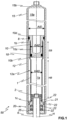
- Figure 1 shows a schematic longitudinal section along the stroke axis H of an embodiment of the gas pressure spring 50 according to the invention.
- the gas pressure spring 50 shown comprises a working piston 2 which is displaceably guided in a working cylinder 1 along a stroke axis H over a stroke range HB, a compensating cylinder 12 which surrounds the working cylinder 1 radially to the stroke axis H, and a hollow-cylindrically shaped compensating piston 10 which is displaceably guided in the compensating cylinder 12 along the stroke axis H relative to the working cylinder 1 and the compensating cylinder 12.
- the working cylinder 1 has an open end 1b along the stroke axis H, wherein the compensating cylinder 12 forms a projection 15 at the open end 1b over the working cylinder 1 with a closed end 15b along the stroke axis H.
- the compensating piston 10 separates a working chamber 1a arranged in the working cylinder 1, a compensating chamber 12a arranged between the working cylinder 1 and the compensating cylinder 12 and a return chamber 15a arranged in the projection 15.
- the compensating piston 10 comprises, on a lower side of the compensating piston 10 facing the working chamber 1a, a cylinder base 10b and a Cylinder jacket 10c rotating around the stroke axis H.
- the cylinder base 10b and a part of the cylinder jacket 10c are arranged in the working cylinder 1.
- the compensating piston 10 is open at an upper side 10a of the compensating piston 10 facing the return chamber 15a.
- a compensating cylinder seal 8 is arranged on the compensating piston 10, sealing the compensating piston 10 to the compensating cylinder 12.
- the compensating piston 10 comprises a cylinder rim 10d projecting radially outwards beyond the cylinder jacket 10c relative to the stroke axis H, wherein the compensating cylinder seal 8 is arranged on the cylinder rim 10d.
- a working cylinder seal 18 sealing the compensating piston 10 to the working cylinder 1 is arranged on the cylinder jacket 10c of the compensating piston 10.
- a piston rod 6 fastened to the working piston 2 is led out of the working cylinder 1 through a sealing device 20.
- the sealing device 20 comprises a fastening element 21, for example made in one piece from aluminum, which is fastened, for example in a form-fitting manner, to the compensating cylinder 12 and to the working cylinder 1.
- the sealing device 20 comprises a number of sealing elements 22, for example four sealing rings, which seal the fastening element 21 of the sealing device 20 to the working cylinder 1, the compensating cylinder 12, and the piston rod 6.
- a distance of the compensating cylinder 12 from the working cylinder 1 measured radially to the stroke axis H in the stroke range HB is greater than in an end region EB of the working cylinder 1 lying between the stroke range HB and the open end 1b of the working cylinder 1.
- the reduced distance in the end region EB is due to the fact that an end region outer diameter EAD of the working cylinder 1, measured radially to the stroke axis H, is larger than a stroke region outer diameter HAD of the working cylinder 1 in the stroke region HB, measured radially to the stroke axis H.
- the end region outer diameter EAD is, for example, 18 mm to 20 mm.
- the stroke region outer diameter HAD is, for example, 16 mm.
- the compensating cylinder inner diameter AID of the compensating cylinder 12 is 25 mm.
- Figure 2 shows a schematic longitudinal section along the stroke axis H of an alternative embodiment of the sealing device 20 of a gas pressure spring 5 according to the invention.
- the sealing device 20 shown comprises an outer part which closes the piston rod end 12c of the compensating cylinder 12 and an inner part which closes the piston rod end 1c of the working cylinder 1.
- the outer part of the sealing device 20 comprises an external fastening element 23, for example a sleeve, which fastens the compensating cylinder 12 to the working cylinder 1, for example by means of a material bond, in particular by means of an adhesive.
- the outer part of the sealing device comprises an external sealing element 24, for example a sealing ring, which seals the working cylinder 1 to the compensating cylinder 12.
- the inner part of the sealing device 20 comprises a guide element 26, for example a guide bushing, which guides the piston rod 6 of the gas spring 5 along the stroke axis H.
- the inner part of the sealing device 20 comprises at least one inner sealing element 27, for example a sealing ring or two sealing rings, which seals the working cylinder 1 to the piston rod 6.
- a disc 25 in particular a metal disc with a corrosion-protected surface, is arranged between the piston rod end 1c of the working cylinder 1 and the piston rod end 12c of the compensating cylinder 12.
- Figure 3 shows schematically a profile of a depth d of a groove on an inner side of a casing wall of the working cylinder of a gas pressure spring according to the invention depending on a position x along the stroke axis of the gas pressure spring.
- the depth of the groove increases linearly along the stroke axis from an extension end AE of the stroke range of the working cylinder facing the piston rod end of the working cylinder in the direction of the open end of the working cylinder in an extension transition area AUB; runs constant in a central area ZB adjoining the extension transition area AUB, decreases linearly in a retraction transition area EUB adjoining the central area ZB and runs in a
- the insertion end area EEB adjoining the insertion transition area EUB up to an insertion end EE of the stroke area facing the open end of the working cylinder remains constant.
Landscapes
- Engineering & Computer Science (AREA)
- General Engineering & Computer Science (AREA)
- Mechanical Engineering (AREA)
- Fluid-Damping Devices (AREA)
Description
- Die Erfindung betrifft eine Gasdruckfeder gemäß dem Oberbegriff des Anspruchs 1 und ein Verfahren zur Herstellung der Gasdruckfeder.
- Aus dem Stand der Technik, sind Gasdruckfedern bekannt, bei denen eine Temperaturabhängigkeit der Federkraft durch ein Ausgleichsmedium ausgeglichen werden soll.
- Die Druckschrift
EP 1 795 777 A2 beschreibt eine Gasfeder mit einem Arbeitszylinder, in dem ein Arbeitskolben verschiebbar geführt ist. Der zwischen dem Arbeitszylinder und einem Ausgleichszylinder gebildete Ringraum ist mit einem Ausgleichsmedium gefüllt, das sich bei Temperaturerhöhung ausdehnt. Das einem Kolbenaustrittsende entgegengesetzte, offene Ende des Arbeitszylinders ist mittels eines topfförmigen Ausgleichskolbens verschlossen. Wenn sich das Ausgleichsmedium ausdehnt, verschiebt es den Ausgleichskolben so, dass sich das Volumen des Arbeitszylinders vergrößert. - Die Druckschrift
DE 31 41 295 A1 betrifft eine Gasfeder, die aus einem Behälter besteht, an dessen Innenwand ein mit der Kolbenstange verbundener Kolben gleitet. Ein mit Ausdehnungsstoff gefüllter Raum befindet sich zwischen einer behälterfesten Trennwand und einem Scheibenkolben, wobei dieser Scheibenkolben eine bewegliche Trennwand für den mit Ausdehnungsstoff gefüllten Raum darstellt. Die Gasfeder umfasst ferner einen Arbeitsraum mit einer unter Druck stehenden Gasfüllung. Bei Temperaturerhöhung dehnt sich der Ausdehnungsstoff aus und bewirkt, dass sich der Scheibenkolben von der behälterfesten Trennwand weiter entfernt, wodurch der Arbeitsraum vergrößert wird. - Bekannte Gasdruckfedern mit Temperaturausgleich sind in der Regel kompliziert aufgebaut, beanspruchen einen deutlich größeren Bauraum als Gasdruckfedern ohne Temperaturausgleich oder können die Temperaturabhängigkeit nicht über den ganzen anwendungsrelevanten Temperaturbereich ausgleichen.
- Die Aufgabe der Erfindung ist es, eine kostengünstige und einfach aufgebaute Gasdruckfeder und ein kostengünstiges und zuverlässiges Verfahren zu deren Herstellung zu schaffen, wobei die Federkraft der Gasdruckfeder über einen möglichst weiten Temperaturbereich von der Temperatur unabhängig ist.
- Die vorliegende Erfindung stellt eine Gasdruckfeder gemäß Anspruch 1 bereit, die die technische Aufgabe löst. Ebenso wird die Aufgabe durch ein Verfahren zur Herstellung der Gasdruckfeder gemäß Anspruch 12 gelöst. Vorteilhafte Ausgestaltungen ergeben sich aus den abhängigen Ansprüchen.
- Die Gasdruckfeder umfasst einen in einem Arbeitszylinder entlang einer Hubachse über einen Hubbereich verschieblich geführten Arbeitskolben. Der Arbeitskolben ist vorzugsweise relativ zu dem Arbeitszylinder entlang der Hubachse verschieblich. Der Arbeitszylinder ist vorzugsweise hohlzylindrisch geformt und/oder koaxial zur Hubachse angeordnet.
- Die Gasdruckfeder umfasst einen den Arbeitszylinder radial zur Hubachse umschließenden Ausgleichszylinder. Der Ausgleichszylinder ist vorzugsweise hohlzylindrisch geformt und/oder koaxial zur Hubachse angeordnet. Der Ausgleichszylinder ist vorzugsweise starr an dem Arbeitszylinder befestigt. Der Ausgleichszylinder ist vorzugsweise einstückig, sodass die Gasdruckfeder besonders einfach herstellbar ist.
- Der Arbeitszylinder weist entlang der Hubachse ein offenes Ende auf. "Offen" bedeutet zumindest, dass ein Gas durch das offene Ende ungehindert aus dem Arbeitszylinder austreten und in den Arbeitszylinder eintreten kann. Vorzugsweise ist das offene Ende vollständig offen.
- An einem dem offenen Ende entlang der Hubachse gegenüberliegenden Kolbenstangen-Ende des Arbeitszylinders ist vorzugsweise eine an dem Arbeitskolben befestigte Kolbenstange der Gasdruckfeder durch eine Dichtvorrichtung aus dem Arbeitszylinder herausgeführt. Durch die Dichtvorrichtung ist das Kolbenstangen-Ende vorzugsweise für ein Gas geschlossen. "Geschlossen" bedeutet, dass am Kolbenstangen-Ende kein Gas aus dem Arbeitszylinder austreten oder in den Arbeitszylinder eintreten kann.
- Der Ausgleichszylinder bildet an dem offenen Ende einen Überstand über den Arbeitszylinder mit einem geschlossenen Ende entlang der Hubachse.
- An einem dem geschlossenen Ende entlang der Hubachse gegenüberliegenden Kolbenstangen-Ende des Ausgleichszylinders ist vorzugsweise die Kolbenstange der Gasdruckfeder durch eine Dichtvorrichtung aus dem Ausgleichszylinder herausgeführt. Durch die Dichtvorrichtung ist das Kolbenstangen-Ende vorzugsweise für ein Gas geschlossen.
- Die Dichtvorrichtung verschließt vorzugsweise das Kolbenstangen-Ende des Ausgleichszylinders und das Kolbenstangen-Ende des Arbeitszylinders. Die Dichtvorrichtung dient vorzugsweise auch als Führungsvorrichtung zur Führung der Kolbenstange entlang der Hubachse. Der Arbeitszylinder ist vorzugsweise über die Dichtvorrichtung an dem Ausgleichszylinder befestigt.
- Die Dichtvorrichtung kann ein, vorzugsweise einstückiges, Befestigungselement, beispielsweise aus Aluminium, umfassen, das an dem Ausgleichszylinder und an dem Arbeitszylinder befestigt, beispielsweise formschlüssig und/oder stoffschlüssig befestigt. insbesondere durch Umformungen des Ausgleichszylinders und/oder des Arbeitszylinders befestigt, ist. Die Dichtvorrichtung kann eine Anzahl von Dichtelementen, beispielsweise Dichtringen, umfassen, die das Befestigungselement der Dichtvorrichtung zum Arbeitszylinder, zum Ausgleichszylinder und/oder zur Kolbenstange abdichten.
- Die Dichtvorrichtung kann einen Außenteil, der das Kolbenstangen-Ende des Ausgleichszylinders verschließt, und einen Innenteil, der das Kolbenstangen-Ende des Arbeitszylinders verschließt, umfassen. Der Vorteil dieses zweiteiligen Aufbaus ist, dass der Innenteil wie bei einer fachüblichen Gasdruckfeder ohne Ausgleichszylinder aufgebaut sein kann.
- Der Außenteil der Dichtvorrichtung kann zumindest ein Außen-Befestigungselement, beispielsweise eine Hülse, umfassen, das den Ausgleichszylinder, beispielsweise formschlüssig, kraftschlüssig und/oder stoffschlüssig, an dem Arbeitszylinder befestigt. Der Außenteil der Dichtvorrichtung kann zumindest ein Außen-Dichtelement, beispielsweise einen Dichtring, umfassen, das den Arbeitszylinder zum Ausgleichszylinder abdichtet.
- Der Innenteil der Dichtvorrichtung kann zumindest ein Führungselement, beispielsweise eine Führungsbuchse, umfassen, das die Kolbenstange entlang der Hubachse führt. Der Innenteil der Dichtvorrichtung kann zumindest ein Innen-Dichtelement, beispielsweise einen Dichtring, umfassen, das den Arbeitszylinder zur Kolbenstange abdichtet.
- Zwischen dem Kolbenstangen-Ende des Arbeitszylinders und dem Kolbenstangen-Ende des Ausgleichszylinders kann eine Scheibe, insbesondere eine Metallscheibe mit einer korrosionsgeschützten Oberfläche, angeordnet sein. Die Scheibe kann die Festigkeit der Dichtvorrichtung erhöhen, insbesondere damit die Dichtvorrichtung bei einem Rollschließen des Ausgleichszylinders nicht beschädigt wird. Die Scheibe kann beispielsweise über eine Rastverbindung mit dem Außen-Befestigungselement der Dichtvorrichtung verbunden sein.
- Der Ausgleichskolben trennt einen in dem Arbeitszylinder angeordneten Arbeitsraum, einen zwischen dem Arbeitszylinder und dem Ausgleichszylinder angeordneten Ausgleichsraum und einen in dem Überstand angeordneten Rückstellraum, vorzugsweise gasdicht, voneinander.
- In dem Ausgleichsraum ist vorzugsweise ein Ausgleichsmedium angeordnet, das den Ausgleichskolben bei Erwärmung des Ausgleichsmediums auf das geschlossene Ende zu verschiebt. Ein Druck des Ausgleichsmediums beträgt beispielsweise von 70 bar bis 350 bar.
- Das Ausgleichsmedium umfasst vorzugsweise einen Dehnstoff, insbesondere ein Dehnwachs, besonders bevorzugt ein Gemisch aus einem Dehnwachs und einem Öl. Das Ausgleichsmedium kann insbesondere aus dem Dehnstoff, dem Dehnwachs oder dem Gemisch aus Dehnwachs und Öl bestehen. Das Ausgleichsmedium kann beispielsweise so ausgestaltet sein wie das in der Druckschrift
EP 1 795 777 A2 beschriebene Ausgleichsmedium. Das Dehnwachs kann beispielsweise so ausgestaltet sein wie das in der AnmeldungDE 10 2020 113 749 beschriebene Dehnwachs. - In dem Rückstellraum ist vorzugsweise ein Rückstellmittel angeordnet, das den Ausgleichskolben bei Abkühlung des Ausgleichsmediums von dem geschlossenen Ende weg verschiebt.
- Das Rückstellmittel umfasst oder ist vorzugsweise ein Rückstellgas, wobei das Rückstellgas bevorzugt das gleiche Gas ist, das als Arbeitsgas den Arbeitsraum füllt. Das Rückstellgas und/oder das Arbeitsgas ist beispielsweise Stickstoff. Das Rückstellmittel kann ein mechanisches Rückstellelement, beispielsweise eine Feder, insbesondere eine Schraubendruckfeder, umfassen oder davon gebildet sein.
- Ein Gasdruck des Arbeitsgases beträgt beispielsweise von 20 bar bis 250 bar. Ein Gasdruck des Rückstellgases beträgt beispielsweise von 20 bar bis 350 bar.
- Ein radial zur Hubachse gemessener Abstand des Ausgleichszylinders von dem Arbeitszylinder ist vorzugsweise in dem Hubbereich größer als in einem zwischen dem Hubbereich und dem offenen Ende des Arbeitszylinders liegenden Endbereich des Arbeitszylinders.
- Der kleinere Abstand im Endbereich bewirkt eine kleinere Querschnittsfläche des Ausgleichsraumes senkrecht zur Hubachse im Endbereich. Dadurch wird der Ausgleichskolben bei einer gegebenen Temperaturerhöhung durch eine Ausdehnung des Ausgleichsmediums weiter zum geschlossenen Ende des Ausgleichszylinders verschoben, sodass der Arbeitsraum stärker vergrößert wird, und eine stärkere Kompensation der Temperaturabhängigkeit der Federkraft der Gasdruckfeder stattfindet.
- Da der Abstand im Hubbereich nicht verkleinert ist, kann der Ausgleichsraum insgesamt noch eine für einen wirksame Temperaturkompensation ausreichende Menge an Ausgleichsmedium aufnehmen.
- Den Abstand im Hubbereich und im Endbereich voneinander unterschiedlich zu gestalten, hat den Nachteil, dass dadurch die Herstellung der Gasdruckfeder aufwändiger wird. Außerdem kann es in einem Übergangsbereich zwischen dem Hubbereich und dem Endbereich zu einer Materialschwächung durch eine Umformung des Arbeitszylinders und/oder Ausgleichszylinders oder zu Undichtigkeiten durch Verbindungsstellen zwischen Teilen das Arbeitszylinders und/oder Ausgleichszylinders kommen. Somit könnte der unterschiedliche Abstand eine zuverlässige Funktion der Gasdruckfeder gefährden.
- Der Abstand ist beispielsweise im Endbereich um 10 % bis 50 %, bevorzugt um 20 % bis 40 %, besonders bevorzugt um 30 %, kleiner als im Hubbereich. Der Abstand beträgt beispielsweise im Endbereich 1 mm bis 8 mm, bevorzugt 2 mm bis 4 mm, besonders bevorzugt 2,5 mm. Der Abstand beträgt beispielsweise im Hubbereich 2 mm bis 12 mm, bevorzugt 3 mm bis 6 mm, besonders bevorzugt 3 mm bis 3,5 mm. Mit den genannten Werten des Abstands kann über einen typischen Einsatz-Temperaturbereich der Gasdruckfeder, beispielsweise von -10 °C bis +60 °C, eine weitgehende, insbesondere vollständige, Kompensation der Temperaturabhängigkeit der Federkraft der Gasdruckfeder erreicht werden.
- Vorzugsweise ist der Abstand des Ausgleichszylinders von dem Arbeitszylinder in dem Endbereich und/oder in dem Hubbereich jeweils unabhängig von einer Position entlang der Hubachse. Der Abstand ist in dieser Ausgestaltung im Endbereich und/oder im Hubbereich jeweils entlang der Hubachse konstant, wodurch die Gasdruckfeder besonders einfach herstellbar ist.
- Ein radial zur Hubachse gemessener Endbereichs-Außendurchmesser des Arbeitszylinders ist in dem Endbereich des Arbeitszylinders vorzugsweise größer als ein radial zur Hubachse gemessener Hubbereichs-Außendurchmesser des Arbeitszylinders in dem Hubbereich. Eine solche Aufweitung des Arbeitszylinders im Endbereich bewirkt einen verringerten Abstand zwischen Arbeitszylinder und Ausgleichszylinder ohne Veränderung des Ausgleichszylinders oder der Form des Arbeitszylinders im Hubbereich. Somit wird der verringerte Abstand mit möglichst wenigen Änderungen gegenüber einer Gasdruckfeder aus dem Stand der Technik erreicht. Die Gasdruckfeder ist damit besonders einfach und kostengünstig, insbesondere unter Verwendung bekannter Komponenten und Verfahren, herstellbar.
- Der Endbereichs-Außendurchmesser des Arbeitszylinders beträgt vorzugsweise von 101 % bis 150 %, bevorzugt von 105 % bis 130 %, besonders bevorzugt von 110 % bis 120 %, meist bevorzugt 112 % bis 113 %, des Hubbereichs-Außendurchmessers des Arbeitszylinders. Der Endbereichs-Außendurchmesser beträgt beispielsweise von 15 mm bis 25 mm, bevorzugt von 16 mm bis 22 mm, besonders bevorzugt von 18 mm bis 21 mm. Der Hubbereichs-Außendurchmesser beträgt beispielsweise von 10 mm bis 20 mm, bevorzugt von 15 mm bis 19 mm, besonders bevorzugt 17 mm bis 18 mm. Mit den genannten Werten der Außendurchmesser kann über einen typischen Einsatz-Temperaturbereich der Gasdruckfeder eine weitgehende Kompensation der Temperaturabhängigkeit der Federkraft der Gasdruckfeder erreicht werden.
- Vorzugsweise ist der Außendurchmesser des Arbeitszylinders in dem Endbereich und/oder in dem Hubbereich jeweils unabhängig von einer Position entlang der Hubachse. Der Außendurchmesser ist in dieser Ausgestaltung im Endbereich und/oder im Hubbereich jeweils entlang der Hubachse konstant, wodurch die Gasdruckfeder besonders einfach herstellbar ist.
- Ein radial zur Hubachse gemessener Ausgleichszylinder-Innendurchmesser des Ausgleichszylinders beträgt vorzugsweise von 110 % bis 200 %, bevorzugt von 140 % bis 170 %, besonders bevorzugt von 150 % bis 160 %, meist bevorzugt 155 % bis 157 %, des Hubbereichs-Außendurchmessers des Arbeitszylinders. Der Ausgleichszylinder-Innendurchmesser beträgt beispielsweise von 20 mm bis 30 mm, bevorzugt von 23 mm bis 27 mm, besonders bevorzugt 25 mm. Mit den genannten Werten des Ausgleichszylinder-Innendurchmessers kann über einen typischen Einsatz-Temperaturbereich der Gasdruckfeder eine weitgehende Kompensation der Temperaturabhängigkeit der Federkraft der Gasdruckfeder erreicht werden.
- Vorzugsweise ist der Innendurchmesser des Ausgleichszylinders unabhängig von einer Position entlang der Hubachse. Der Innendurchmesser des Ausgleichszylinders ist in dieser Ausgestaltung entlang der Hubachse konstant, wodurch die Gasdruckfeder besonders einfach herstellbar ist.
- Der Hubbereich und der Endbereich des Arbeitszylinders sind vorzugsweise einstückig miteinander verbunden, sodass die Gasdruckfeder besonders einfach herstellbar ist. Beispielsweise kann der Arbeitszylinder in dem Endbereich quer zur Hubachse relativ zum Hubbereich aufgeweitet sein.
- Der Hubbereich und der Endbereich können beispielsweise stoffschlüssig miteinander verbunden, insbesondere miteinander verschweißt, verlötet und/oder verklebt, sein. Der Hubbereich und der Endbereich können beispielsweise formschlüssig und/oder kraftschlüssig miteinander verbunden, insbesondere miteinander verschraubt, verrastet und/oder verklemmt, sein.
- Der Arbeitszylinder kann beispielsweise ein Metall, insbesondere einen Stahl, und/oder einen Kunststoff umfassen oder daraus bestehen.
- Eine Wandstärke des Arbeitszylinders radial zur Hubachse ist vorzugsweise im Hubbereich und im Endbereich des Arbeitszylinders gleich. Die Wandstärke gilt insbesondere als gleich, wenn sie bis auf eine durch eine Aufweitung des Arbeitszylinders im Endbereich bewirkte Verringerung der Wandstärke, beispielsweise bis auf eine Verringerung um bis zu 0,2 mm, gleich ist. Die Wandstärke ist vorzugsweise unabhängig von einer Position entlang der Hubachse. Die Wandstärke des Arbeitszylinders ist in dieser Ausgestaltung entlang der Hubachse konstant, wodurch die Gasdruckfeder besonders einfach herstellbar ist.
- Eine Wandstärke des Ausgleichszylinders radial zur Hubachse ist vorzugsweise unabhängig von einer Position entlang der Hubachse. Die Wandstärke des Ausgleichszylinders ist in dieser Ausgestaltung entlang der Hubachse konstant, wodurch die Gasdruckfeder besonders einfach herstellbar ist.
- Der Ausgleichskolben ist vorzugsweise einstückig, sodass die Gasdruckfeder besonders einfach herstellbar ist.
- Der Ausgleichskolben umfasst bevorzugt Aluminium oder einen Kunststoff. Besonders bevorzugt besteht der Ausgleichskolben aus Aluminium oder einem Kunststoff.
- Der Ausgleichskolben ist vorzugsweise hohlzylindrisch geformt und insbesondere koaxial zur Hubachse angeordnet.
- Der Ausgleichskolben weist vorzugsweise an einer Unterseite des Ausgleichskolbens einen Zylinderboden auf. Der Zylinderboden ist vorzugsweise senkrecht zur Hubachse ausgerichtet und/oder geschlossen.
- Der Ausgleichskolben umfasst vorzugsweise einen um die Hubachse umlaufenden Zylindermantel. Der Zylindermantel ist vorzugsweise geschlossen.
- Der Ausgleichskolben ist an einer dem Zylinderboden entlang der Hubachse gegenüberliegenden Oberseite des Ausgleichskolbens offen. Daraus ergibt sich der Vorteil, dass das Innere des Ausgleichskolbens als Teil des Arbeitsraums oder des Rückstellraums dienen kann, sodass die Gasdruckfeder besonders kompakt aufgebaut sein kann.
- Der Ausgleichskolben ist vorzugsweise topfförmig, wobei der Zylinderboden einem Topfboden entspricht und der Zylindermantel einer Topfwand.
- Ein hohlzylindrischer oder topfförmiger Ausgleichskolben hat die Vorteile, dass er den Arbeitsraum, den Ausgleichsraum und den Rückstellraum mit einer besonders geringen Masse voneinander trennen kann.
- An dem Ausgleichskolben ist vorzugsweise eine den Ausgleichskolben zum Ausgleichszylinder, insbesondere gasdicht, abdichtende Ausgleichszylinderdichtung angeordnet. Die Ausgleichszylinderdichtung kann an dem Ausgleichskolben befestigt sein. Die Ausgleichszylinderdichtung kann einen, insbesondere koaxial, um die Hubachse umlaufenden Dichtring, insbesondere einen O-Ring, umfassen oder davon gebildet sein.
- Der Ausgleichskolben umfasst vorzugsweise eine, bevorzugt an die Oberseite angrenzende, radial zur Hubachse nach außen über den Zylindermantel überstehende Zylinderkrempe, wobei an der Zylinderkrempe die Ausgleichszylinderdichtung angeordnet, insbesondere befestigt, ist. Mit Hilfe der Zylinderkrempe kann die Ausgleichszylinderdichtung mit geringem Materialaufwand zuverlässig dichtend in Kontakt mit dem Ausgleichszylinder gebracht werden.
- Die Oberseite des Ausgleichskolbens ist vorzugsweise zum Rückstellraum offen. Dadurch wird das Innere des Ausgleichskolbens Teil des Rückstellraums, sodass für das Rückstellmittel relativ zum Arbeitsgas mehr Volumen zur Verfügung steht. Mit einem relativ zum Rückstellmittelvolumen kleineren Arbeitsgasvolumen kann die Temperaturabhängigkeit der Federkraft einfacher ausgeglichen werden.
- An dem Ausgleichskolben, bevorzugt an dem Zylindermantel des Ausgleichskolbens, oder an dem Arbeitszylinder ist vorzugsweise eine den Ausgleichskolben zum Arbeitszylinder, insbesondere gasdicht, abdichtende Arbeitszylinderdichtung angeordnet, insbesondere befestigt. Die Arbeitszylinderdichtung kann einen, insbesondere koaxial, um die Hubachse umlaufenden Dichtring, insbesondere einen O-Ring, umfassen oder davon gebildet sein.
- Der Ausgleichskolben, bevorzugt der Zylindermantel des Ausgleichskolbens und besonders bevorzugt auch der Zylinderboden des Ausgleichskolbens, ist vorzugsweise zumindest abschnittsweise in dem Endbereich des Arbeitszylinders angeordnet. Dadurch wird das Volumen des Ausgleichsraums und/oder des Rückstellraums relativ zum Volumen des Arbeitsraums vergrößert, wodurch eine wirksamere Kompensation der Temperaturabhängigkeit der Federkraft der Gasdruckfeder erreicht wird.
- Der Ausgleichskolben ist vorzugsweise vollständig in dem Ausgleichszylinder angeordnet. Daraus ergibt sich der Vorteil, dass sich eine entlang der Hubachse gemessene Länge der Gasdruckfeder nicht ändert, wenn sich der Ausgleichskolben verschiebt. Die Länge der Gasdruckfeder ist somit nicht temperaturabhängig.
- Die Gasdruckfeder umfasst vorzugsweise eine Anzahl von, beispielsweise ein, zwei, drei, vier, fünf oder mehr, Stützelementen, wobei die Anzahl von Stützelementen den Arbeitszylinder an dem Ausgleichszylinder abstützt. Die Stützelemente verhindern vorteilhafterweise Relativbewegungen des Arbeitszylinders relativ zu dem Ausgleichszylinder, die eine Abdichtung des Ausgleichskolbens zum Arbeitszylinder oder zum Ausgleichszylinder oder eine Verschieblichkeit des Ausgleichskolbens entlang der Hubachse beeinträchtigen könnten.
- Die Stützelemente sind vorzugsweise um die Hubachse voneinander beabstandet angeordnet, und/oder die Stützelemente weisen vorzugsweise Durchbrechungen entlang der Hubachse auf. Dadurch behindern die Stützelemente eine Expansion oder Kompression eines Ausgleichsmediums in dem Ausgleichsraum entlang der Hubachse zwischen dem Arbeitszylinder und dem Ausgleichszylinder nicht wesentlich.
- Die Stützelemente sind vorzugsweise gleichmäßig um die Hubachse verteilt. Dadurch können die Stützelemente den Arbeitszylinder besonders zuverlässig an dem Ausgleichszylinder abstützen.
- Die Stützelemente sind vorzugsweise an dem Endbereich des Arbeitszylinders angeordnet. Da der Endbereich an den Ausgleichskolben angrenzt, können die Stützelemente an dem Endbereich besonders wirksam die Abdichtung und Verschieblichkeit des Ausgleichskolbens sicherstellen.
- Die Stützelemente können als entlang der Hubachse durchbrochener Ring ausgestaltet sein, der zur Hubachse koaxial angeordnet ist und den Arbeitszylinder mechanisch mit dem Ausgleichszylinder verbindet. Der Ring ist vorzugsweise an dem Hubbereich des Arbeitszylinders angeordnet. An dem Hubbereich behindert der Ring eine Expansion oder Kompression eines Ausgleichsmediums in dem Ausgleichsraum entlang der Hubachse besonders wenig.
- Die Anzahl von Stützelementen ist vorzugsweise einstückig mit dem Arbeitszylinder oder mit dem Ausgleichszylinder. Dadurch wird die Anzahl der Bauteile der Gasdruckfeder reduziert, sodass die Gasdruckfeder besonders einfach, schnell und kostengünstig herstellbar ist.
- Die Stützelemente können beispielsweise durch Umformungen des Arbeitszylinders und/oder des Ausgleichszylinders gebildet sein. Dadurch können die Stützelemente besonders schnell und einfach gebildet werden. Die Umformungen umfassen beispielsweise Aufweitungen des Arbeitszylinders an den Ausgleichszylinder und/oder, insbesondere punktförmige, Vertiefungen des Ausgleichszylinders an den Arbeitszylinder. Aufgrund des geringen Abstands des Arbeitszylinders von dem Ausgleichszylinder in dem Endbereich können die Stützelemente besonders einfach in dem Endbereich durch die Umformungen gebildet werden.
- Das Verfahren zur Herstellung der Gasdruckfeder umfasst vorzugsweise ein Bereitstellen eines Arbeitszylinderrohlings wobei der Arbeitszylinderrohling hohlzylindrisch geformt ist und einen von einer Position entlang seiner Längsachse unabhängigen Außendurchmesser quer zur Längsachse hat. Der Außendurchmesser ist also entlang der Hubachse konstant. Der Arbeitszylinderrohling kann insbesondere ein Arbeitszylinder einer bekannten Gasdruckfeder sein. Der Arbeitszylinderrohling hat vorzugsweise von einem Azimut bezüglich seiner Längsachse abhängige Materialeigenschaften, beispielsweise durch eine Schweißnaht entlang der Längsachse. Ein solcher Arbeitszylinderrohling ist besonders einfach und kostengünstig herstellbar, beispielsweise indem er aus Stahl gezogen und geschweißt wird.
- Das Verfahren umfasst vorzugsweise ein Umformen des Arbeitszylinderrohlings zu dem Arbeitszylinder der Gasdruckfeder, wobei das Umformen ein Aufweiten des Außendurchmessers des Arbeitszylinderrohlings in einem Endbereich des Arbeitszylinderrohlings umfasst.
- Das Verfahren umfasst vorzugsweise ein Anordnen des Ausgleichskolbens der Gasdruckfeder zumindest abschnittsweise in dem Endbereich des Arbeitszylinders der Gasdruckfeder.
- Das Aufweiten umfasst vorzugsweise ein Einführen eines Dorns in den Endbereich und bevorzugt ein Anordnen einer um die Längsachse umlaufende Hülse um den Endbereich des Arbeitszylinderrohlings vor dem Einführen des Dorns, sodass der Endbereich nach dem Aufweiten an der Hülse anliegt. Dadurch lässt sich vorteilhafterweise der Durchmesser eines Arbeitszylinderrohlings, dessen Materialeigenschaften von einem Azimut bezüglich seiner Längsachse abhängig sind, zu einem von dem Azimut unabhängigen Durchmesser aufweiten.
- Das Verfahren umfasst vorzugsweise ein Umformen des Arbeitszylinders der Gasdruckfeder und/oder des Ausgleichszylinders der Gasdruckfeder zur Erzeugung einer Anzahl von Stützelementen, wobei die Anzahl von Stützelementen den Arbeitszylinder an dem Ausgleichszylinder abstützt. Die Stützelemente können wie oben beschrieben ausgestaltet sein, woraus sich die dort genannten Vorteile ergeben.
- Das Umformen zur Erzeugung der Stützelemente umfasst beispielsweise ein Aufweiten des Arbeitszylinders an den Ausgleichszylinder und/oder ein, insbesondere punktförmiges, Vertiefen des Ausgleichszylinders an den Arbeitszylinder.
- Besonders bevorzugt erfolgt das Aufweiten des Arbeitszylinders zur Erzeugung der Stützelemente im gleichen Schritt wie das Aufweiten des Endbereichs des Arbeitszylinderrohlings zu dem Arbeitszylinder. Dazu kann beispielsweise ein Dorn in den Endbereich des Arbeitszylinderrohlings eingeführt werden, wobei der Dorn vorzugsweise eine Anzahl von Vorsprüngen zur Erzeugung der Stützelemente während des Aufweitens des Endbereichs des Arbeitszylinderrohlings zu dem Arbeitszylinder aufweist.
- Das Verfahren umfasst vorzugsweise ein Umformen oder eine zerspanende Bearbeitung eines Ausgleichskolbenrohlings zu dem Ausgleichskolben. Ein Umformen erlaubt eine Herstellung des Ausgleichskolbens mit besonders geringem Materialbedarf. Der Ausgleichskolben kann beispielsweise durch Tiefziehen eines Ausgleichskolbenrohlings aus Aluminium hergestellt werden. Der Ausgleichskolben kann beispielsweise durch Umformen aus einem Ausgleichskolbenrohling aus Stahl hergestellt werden.
- Der Ausgleichskolbenrohling kann beispielsweise hohlzylindrisch geformt sein. Der hohlzylindrische Ausgleichskolbenrohling kann an einem Ende entlang seiner Längsachse aufgeweitet werden, beispielsweise von einem Innendurchmesser von 18 mm auf einen Innendurchmesser von 23 mm, um eine nach außen vorstehende Zylinderkrempe zu bilden. Der hohlzylindrische Ausgleichskolbenrohling kann an seinem anderen Ende durch Rollschließen und/oder Plasmaschweißen verschlossen werden, um einen geschlossenen Zylinderboden zu bilden. In den Zylindermantel des Ausgleichszylinderrohlings können um seine Längsachse umlaufende Sicken eingerollt werden, um die Ausgleichszylinderdichtung und/oder die Arbeitszylinderdichtung teilweise aufzunehmen.
- Der Arbeitszylinder der Gasdruckfeder weist vorzugsweise an einer Innenseite einer Mantelwand des Arbeitszylinders eine Nut auf, durch die ein in dem Arbeitszylinder enthaltenes Gas entlang der Hubachse der Gasdruckfeder an dem Arbeitskolben der Gasdruckfeder vorbei strömen kann.
- Eine orthogonal zur Hubachse ausgerichtete Querschnittsfläche der Nut variiert vorzugsweise entlang der Hubachse. Vorzugsweise ist die Querschnittsfläche an den Enden des Hubbereichs des Arbeitszylinders minimal und in einem zentralen Abschnitt zwischen den Enden des Hubbereichs maximal. Dadurch wird an den Enden des Hubbereichs ein höherer Strömungswiderstand auf das Gas bewirkt. Folglich bewirkt die Gasdruckfeder nahe eines maximalen Einschubs der Kolbenstange in die Gasdruckfeder und nahe eines maximalen Ausschubs der Kolbenstange aus der Gasdruckfeder jeweils eine höhere Dämpfkraft als in dazwischen liegenden Positionen der Kolbenstange. Die erhöhte Dämpfkraft nahe des maximalen Einschubs und des maximalen Ausschubs bewirkt, dass eine Bewegung der Kolbenstange dort stärker abgebremst wird, sodass eine Beschädigung der Gasdruckfeder durch Erreichen des maximalen Einschubs oder Ausschubs mit hoher Geschwindigkeit vermieden wird.
- Die Querschnittsfläche der Nut variiert vorzugsweise durch eine variable Tiefe der Nut senkrecht zu der Innenseite der Mantelwand des Arbeitszylinders.
- In einer, insbesondere für die unten beschriebene Verwendung der Gasdruckfeder in einem Antriebssystem, besonders vorteilhaften Ausgestaltung steigt die Querschnittsfläche der Nut entlang der Hubachse von einem dem Kolbenstangen-Ende des Arbeitszylinders zugewandten Ausschub-Ende des Hubbereichs des Arbeitszylinders in Richtung zum offenen Ende des Arbeitszylinders in einem Ausschub-Übergangsbereich, vorzugsweise linear, an; verläuft in einem sich an den Ausschub -Übergangsbereich anschließenden Zentralbereich konstant, fällt in einem sich an den Zentralbereich anschließenden Einschub-Übergangsbereich, vorzugsweise linear, ab und verläuft in einem sich an den Einschub-Übergangsbereich anschließenden Einschub-Endbereich bis zu einem dem offenen Ende des Arbeitszylinders zugewandten Einschub-Ende des Hubbereichs konstant.
- Durch den vorgenannten Verlauf der Querschnittsfläche wird eine hohe Dämpfkraft erreicht, wenn die Kolbenstange in die Gasdruckfeder eingeschoben wird und sich dem maximalen Einschub nähert. Dadurch kann insbesondere verhindert werden, dass sich eine von der Gasdruckfeder unterstützte Klappe zu schnell vollständig schließt, was sonst zu Beschädigungen der Klappe oder Verletzungen eines Bedieners der Klappe führen könnte.
- Der Arbeitskolben der Gasdruckfeder umfasst vorzugsweise eine Dichtung, insbesondere einen Dichtring, die den Kolben zu einer Innenseite einer Mantelwand des Arbeitszylinders abdichtet. Die Dichtung ist vorzugsweise so steif, dass sie nicht in eine an der Innenseite der Mantelwand angeordnete Nut eindringt. Dadurch wird verhindert, dass die Dichtung die Nut verschließt, wodurch die Gasdruckfeder blockiert würde.
- Die Erfindung betrifft ein Antriebssystem für eine Klappe mit
- a. einer erfindungsgemäßen Gasdruckfeder zur Unterstützung der Klappe und
- b. einem elektromechanischen Antrieb, beispielsweise einem Linearantrieb, insbesondere einem Spindelantrieb, zum Antrieb der Klappe.
- Bei der Klappe kann es sich beispielsweise um eine Klappe eines Fahrzeugs, insbesondere um eine Motorhaube, eine Kofferraumklappe, eine Gepäckraumklappe oder eine Flügeltür, handeln.
- Antriebssysteme für eine Klappe mit einer Gasdruckfeder zur Unterstützung der Klappe und einem elektromechanischen Antrieb zum Antrieb der Klappe sind im Stand der Technik bekannt. Bis auf die Verwendung einer erfindungsgemäßen anstelle einer gattungsgemäßen Gasdruckfeder kann das erfindungsgemäße Antriebssystem wie ein entsprechendes Antriebssystem aus dem Stand der Technik, beispielsweise aus
DE 103 13 440 A1 oderDE 10 2008 045 903 A1 , aufgebaut sein. - Die Gasdruckfeder des Antriebssystems dient dazu, die Klappe in einer beliebigen Stellung gegen die Schwerkraft zu halten, während der elektromechanische Antrieb dazu dient, die Klappe zu öffnen und zu schließen. Zusätzlich kann wie in
DE 103 13 440 A1 undDE 10 2008 045 903 A1 eine manuelle Betätigung der Klappe vorgesehen sein. - Die Gasdruckfeder muss eine so hohe Federkraft aufweisen, dass sie die Klappe auch bei niedrigen Umgebungstemperaturen halten kann. Da die Federkraft bei üblichen Gasdruckfedern mit steigender Temperatur steigt, führt dies dazu, dass bei hohen Temperaturen von dem elektromechanischen Antrieb oder einem Bediener eine sehr hohe Kraft aufgebracht werden muss, um die Klappe zu schließen. Daher muss das Antriebssystem einen sehr kraftvollen elektromechanischen Antrieb umfassen, der teuer ist, viel Bauraum beansprucht und im Betrieb viel Energie verbraucht. Außerdem kommt es zu einem hohen Verschleiß des elektromechanischen Antriebs und von anderen mit der Klappe mechanisch verbundenen Teilen, beispielsweise Scharnieren.
- Im Stand der Technik werden diese Probleme durch Verwendung eines Federbeins anstelle der Gasdruckfeder umgangen (z.B.
DE 10 2008 045 903 A1 , Abs. [0021]). Ein Federbein hat zwar eine nahezu temperaturunabhängige Federkraft, ist aber größer, schwerer und teurer als eine Gasdruckfeder mit vergleichbarer Federkraft. - Im Verhältnis eines zur Stützung einer gegebenen Last ausgelegten Federbeins hat eine zur Stützung der gleichen Last ausgelegte Gasdruckfeder aufgrund ihres hohen Gasdrucks eine höhere Dämpfkraft. Das gilt wegen des fluiddynamisch mit zunehmender Einschubgeschwindigkeit der Kolbenstange in die Gasdruckfeder steigenden Strömungswiderstands des Gases der Gasdruckfeder insbesondere für hohe Einschubgeschwindigkeiten. Dadurch bremst eine Gasdruckfeder langsame Bewegungen der Klappe, die bei einer bestimmungsgemäßen Betätigung der Klappe durch den Antrieb auftreten, nur geringfügig ab. Schnelle Bewegungen der Klappe, die beispielsweise auftreten können, wenn die Klappe durch eine Fehlbedienung oder eine Fehlfunktion des Antriebs herabfällt, bremst die Gasdruckfeder hingegen stark ab.
- Somit ist das Antriebssystem durch die Verwendung einer Gasdruckfeder anstatt eines Federbeins besonders leicht, kostengünstig, platzsparend und sicher. Durch die Verwendung einer erfindungsgemäßen, temperaturkompensierten Gasdruckfeder anstelle einer fachüblichen Gasdruckfeder werden die vorgenannten Nachteile fachüblicher Gasdruckfedern überkommen.
-
-
Figur 1 zeigt beispielhaft einen schematischen Längsschnitt entlang der Hubachse einer erfindungsgemäßen Ausgestaltung der Gasdruckfeder. -
Figur 2 zeigt einen schematischen Längsschnitt einer alternativen Ausgestaltung der Dichtvorrichtung einer erfindungsgemäßen Gasdruckfeder. -
Figur 3 zeigt schematisch einen Verlauf einer Tiefe einer Nut an einer Innenseite einer Mantelwand des Arbeitszylinders einer erfindungsgemäßen Gasdruckfeder. -
Figur 1 zeigt einen schematischen Längsschnitt entlang der Hubachse H einer erfindungsgemäßen Ausgestaltung der Gasdruckfeder 50. - Die gezeigte Gasdruckfeder 50 umfasst einen in einem Arbeitszylinder 1 entlang einer Hubachse H über einen Hubbereich HB verschieblich geführten Arbeitskolben 2, einen den Arbeitszylinder 1 radial zur Hubachse H umschließenden Ausgleichszylinder 12, und einen in dem Ausgleichszylinder 12 entlang der Hubachse H relativ zu dem Arbeitszylinder 1 und dem Ausgleichszylinder 12 verschieblich geführten und hohlzylindrisch geformten Ausgleichskolben 10.
- Der Arbeitszylinder 1 weist entlang der Hubachse H ein offenes Ende 1b auf, wobei der Ausgleichszylinder 12 an dem offenen Ende 1b einen Überstand 15 über den Arbeitszylinder 1 mit einem geschlossenen Ende 15b entlang der Hubachse H bildet.
- Der Ausgleichskolben 10 trennt einen in dem Arbeitszylinder 1 angeordneten Arbeitsraum 1a, einen zwischen dem Arbeitszylinder 1 und dem Ausgleichszylinder 12 angeordneten Ausgleichsraum 12a und einen in dem Überstand 15 angeordneten Rückstellraum 15a voneinander.
- Der Ausgleichskolben 10 umfasst an einer dem Arbeitsraum 1a zugewandten Unterseite des Ausgleichskolbens 10 einen Zylinderboden 10b und einen um die Hubachse H umlaufenden Zylindermantel 10c. Der Zylinderboden 10b und ein Teil des Zylindermantels 10c sind in dem Arbeitszylinder 1 angeordnet. Der Ausgleichskolben 10 ist an einer dem Rückstellraum 15a zugewandten Oberseite 10a des Ausgleichskolbens 10 offen.
- An dem Ausgleichskolben 10 ist eine den Ausgleichskolben 10 zum Ausgleichszylinder 12 abdichtende Ausgleichszylinderdichtung 8 angeordnet.
- Der Ausgleichskolben 10 umfasst eine radial zur Hubachse H nach außen über den Zylindermantel 10c überstehende Zylinderkrempe 10d, wobei die Ausgleichszylinderdichtung 8 an der Zylinderkrempe 10d angeordnet ist.
- An dem Zylindermantel 10c des Ausgleichskolbens 10 ist eine den Ausgleichskolben 10 zum Arbeitszylinder 1 abdichtende Arbeitszylinderdichtung 18 angeordnet.
- An einem dem offenen Ende 1b entlang der Hubachse H gegenüberliegenden Kolbenstangen-Ende 1c des Arbeitszylinders 1 ist eine an dem Arbeitskolben 2 befestigte Kolbenstange 6 durch eine Dichtvorrichtung 20 aus dem Arbeitszylinder 1 herausgeführt.
- Die Dichtvorrichtung 20 umfasst ein, beispielsweise einstückig aus Aluminium gefertigtes, Befestigungselement 21, das an dem Ausgleichszylinder 12 und an dem Arbeitszylinder 1, beispielsweise formschlüssig, befestigt, ist. Die Dichtvorrichtung 20 umfasst eine Anzahl von Dichtelementen 22, beispielsweise vier Dichtringe, umfassen, die das Befestigungselement 21 der Dichtvorrichtung 20 zum Arbeitszylinder 1, zum Ausgleichszylinder 12 und zur Kolbenstange 6 abdichten.
- Ein radial zur Hubachse H gemessener Abstand des Ausgleichszylinders 12 von dem Arbeitszylinder 1 in dem Hubbereich HB ist größer als in einem zwischen dem Hubbereich HB und dem offenen Ende 1b des Arbeitszylinders 1 liegenden Endbereich EB des Arbeitszylinders 1.
- Der im Endbereich EB verkleinerte Abstand kommt dadurch zustande, dass ein radial zur Hubachse H gemessener Endbereichs-Außendurchmesser EAD des Arbeitszylinders 1 größer ist als ein radial zur Hubachse H gemessener Hubbereichs-Außendurchmesser HAD des Arbeitszylinders 1 in dem Hubbereich HB. Der Endbereichs-Außendurchmesser EAD beträgt beispielsweise 18 mm bis 20 mm. Der Hubbereichs-Außendurchmesser HAD beträgt beispielsweise 16 mm.
- Ein Ausgleichszylinder-Innendurchmesser AID des Ausgleichszylinders 12 beträgt beispielsweise 25 mm.
-
Figur 2 zeigt einen schematischen Längsschnitt entlang der Hubachse H einer alternative Ausgestaltung der Dichtvorrichtung 20 einer erfindungsgemäßen Gasdruckfeder 5. - Die in
Figur 2 gezeigte Dichtvorrichtung 20 umfasst einen Außenteil, der das Kolbenstangen-Ende 12c des Ausgleichszylinders 12 verschließt, und einen Innenteil, der das Kolbenstangen-Ende 1c des Arbeitszylinders 1 verschließt. - Der Außenteil der Dichtvorrichtung 20 umfasst ein Außen-Befestigungselement 23, beispielsweise eine Hülse, das den Ausgleichszylinder 12, beispielsweise stoffschlüssig, insbesondere durch einen Klebstoff, an dem Arbeitszylinder 1 befestigt. Der Außenteil der Dichtvorrichtung umfasst ein Außen-Dichtelement 24, beispielsweise einen Dichtring, das den Arbeitszylinder 1 zum Ausgleichszylinder 12 abdichtet.
- Der Innenteil der Dichtvorrichtung 20 umfasst ein Führungselement 26, beispielsweise eine Führungsbuchse, das die Kolbenstange 6 der Gasdruckfeder 5 entlang der Hubachse H führt. Der Innenteil der Dichtvorrichtung20 umfasst zumindest ein Innen-Dichtelement 27, beispielsweise ein Dichtring oder zwei Dichtringe, das den Arbeitszylinder 1 zur Kolbenstange 6 abdichtet.
- Zwischen dem Kolbenstangen-Ende 1c des Arbeitszylinders 1 und dem Kolbenstangen-Ende 12c des Ausgleichszylinders 12 ist beispielsweise eine Scheibe 25, insbesondere eine Metallscheibe mit einer korrosionsgeschützten Oberfläche, angeordnet.
-
Figur 3 zeigt schematisch einen Verlauf einer Tiefe d einer Nut an einer Innenseite einer Mantelwand des Arbeitszylinders einer erfindungsgemäßen Gasdruckfeder abhängig von einer Position x entlang der Hubachse der Gasdruckfeder. - Im dargestellten Beispiel steigt die Tiefe der Nut entlang der Hubachse von einem dem Kolbenstangen-Ende des Arbeitszylinders zugewandten Ausschub-Ende AE des Hubbereichs des Arbeitszylinders in Richtung zum offenen Ende des Arbeitszylinders in einem Ausschub-Übergangsbereich AUB linear an; verläuft in einem sich an den Ausschub -Übergangsbereich AUB anschließenden Zentralbereich ZB konstant, fällt in einem sich an den Zentralbereich ZB anschließenden Einschub-Übergangsbereich EUB linear ab und verläuft in einem sich an den Einschub-Übergangsbereich EUB anschließenden Einschub-Endbereich EEB bis zu einem dem offenen Ende des Arbeitszylinders zugewandten Einschub-Ende EE des Hubbereichs konstant.
Liste der Bezugszeichen 1 Arbeitszylinder 23 Außen-Befestigungselement 1a Innerer Arbeitsraum 24 Außen-Dichtelement 1b offenes Ende 25 Scheibe 1c Kolbenstangen-Ende 26 Führungselement 2 Arbeitskolben 27 Innen-Dichtelement 6 Kolbenstange 50 Gasdruckfeder 8 Ausgleichszylinderdichtung 10 Ausgleichskolben AE Ausschub-Ende 10b Zylinderboden AID Ausgleichszylinder-Innendurchmesser 10c Zylindermantel AUB Ausschub-Übergangsbereich 10d Zylinderkrempe d Tiefe 12 Ausgleichszylinder EAD Endbereichs-Außendurchmesser 12a Ausgleichsraum EB Endbereich 12c Kolbenstangen-Ende EE Einschub-Ende 15 Überstand EEB Einschub-Endbereich 15a Rückstellraum EUB Einschub-Übergangsbereich 15b geschlossenes Ende H Hubachse 18 Arbeitszylinderdichtung HAD Hubbereichs-Außendurchmesser 20 Dichtvorrichtung HB Hubbereich 21 Befestigungselement x Position entlang der Hubachse 22 Dichtelement ZB Zentralbereich
Claims (15)
- Gasdruckfeder (50), umfassenda. einen in einem Arbeitszylinder (1) entlang einer Hubachse (H) über einen Hubbereich (HB) verschieblich geführten Arbeitskolben (2),b. einen den Arbeitszylinder (1) radial zur Hubachse (H) umschließenden Ausgleichszylinder (12), undc. einen in dem Ausgleichszylinder (12) entlang der Hubachse (H) verschieblich geführten Ausgleichskolben (10),d. wobei der Arbeitszylinder (1) entlang der Hubachse (H) ein offenes Ende (1b) aufweist,e. wobei der Ausgleichszylinder (12) an dem offenen Ende (1b) einen Überstand (15) über den Arbeitszylinder (1) mit einem geschlossenen Ende (15b) entlang der Hubachse (H) bildet,f. wobei der Ausgleichskolben (10) einen in dem Arbeitszylinder (1) angeordneten Arbeitsraum (1a), einen zwischen dem Arbeitszylinder (1) und dem Ausgleichszylinder (12) angeordneten Ausgleichsraum (12a) und einen in dem Überstand (15) angeordneten Rückstellraum (15a) voneinander trennt,g. wobei ein radial zur Hubachse (H) gemessener Abstand des Ausgleichszylinders (12) von dem Arbeitszylinder (1) in dem Hubbereich (HB) größer ist als in einem zwischen dem Hubbereich (HB) und dem offenen Ende (1b) des Arbeitszylinders (1) liegenden Endbereich (EB) des Arbeitszylinders (1),
dadurch gekennzeichnet, dassh. der Ausgleichskolben (10) zumindest abschnittsweise in dem Endbereich (EB) des Arbeitszylinders (1) angeordnet ist. - Gasdruckfeder (50) nach Anspruch 1,
dadurch gekennzeichnet, dass
eine Wandstärke (WS) des Arbeitszylinders (1) radial zur Hubachse (H) im Hubbereich (HB) und im Endbereich (EB) des Arbeitszylinders (1) gleich ist. - Gasdruckfeder (50) nach einem der Ansprüche 1 bis 2,
dadurch gekennzeichnet, dass
der Ausgleichskolben (10) einstückig ist. - Gasdruckfeder (50) nach einem der Ansprüche 1 bis 3,
dadurch gekennzeichnet, dass
der Ausgleichskolben (10) Aluminium oder einen Kunststoff umfasst. - Gasdruckfeder (50) nach einem der Ansprüche 1 bis 4,
dadurch gekennzeichnet, dass
der Ausgleichskolben (10) hohlzylindrisch geformt ist, wobei der Ausgleichskolben (10)a. an einer Unterseite des Ausgleichskolbens (10) einen geschlossenen Zylinderboden (10b) umfasst,b. einen um die Hubachse (H) umlaufenden Zylindermantel (10c) umfasst,c. an einer dem Zylinderboden (10b) entlang der Hubachse (H) gegenüberliegenden Oberseite des Ausgleichskolbens (10) offen ist undd. wobei an dem Ausgleichskolben (10) eine den Ausgleichskolben (10) zum Ausgleichszylinder (12) abdichtende Ausgleichszylinderdichtung (8) angeordnet ist. - Gasdruckfeder (50) nach Anspruch 5,
dadurch gekennzeichnet, dass
der Ausgleichskolben (10)a. eine radial zur Hubachse (H) nach außen über den Zylindermantel (10c) überstehende Zylinderkrempe (10d) umfasst,b. wobei die Ausgleichszylinderdichtung (8) an der Zylinderkrempe (10d) angeordnet ist. - Gasdruckfeder (50) nach einem der Ansprüche 5 bis 6,
dadurch gekennzeichnet, dass
die Oberseite des Ausgleichskolbens (10) zum Rückstellraum (15a) offen ist. - Gasdruckfeder (50) nach einem der Ansprüche 1 bis 7,
dadurch gekennzeichnet, dass
an dem Ausgleichskolben (10) eine den Ausgleichskolben (10) zum Arbeitszylinder (1) abdichtende Arbeitszylinderdichtung (18) angeordnet ist. - Gasdruckfeder (50) nach einem der Ansprüche 1 bis 8,
dadurch gekennzeichnet, dass
die Gasdruckfeder (50) eine Anzahl von Stützelementen umfasst, wobei die Anzahl von Stützelementen den Arbeitszylinder (1) an dem Ausgleichszylinder (12) abstützt. - Gasdruckfeder (50) nach Anspruch 9,
dadurch gekennzeichnet, dass
die Anzahl von Stützelementen einstückig mit dem Arbeitszylinder (1) oder mit dem Ausgleichszylinder (12) ist. - Gasdruckfeder (50) nach einem der Ansprüche 1 bis 10,
dadurch gekennzeichnet, dass
der Ausgleichskolben (10) vollständig in dem Ausgleichszylinder (12) angeordnet ist. - Verfahren zur Herstellung der Gasdruckfeder (50) nach einem der Ansprüche 1 bis 11,
gekennzeichnet durch folgende Schritte:a. Bereitstellen eines Arbeitszylinderrohlings, wobei der Arbeitszylinderrohling hohlzylindrisch geformt ist und einen von einer Position entlang seiner Längsachse unabhängigen Außendurchmesser quer zur Längsachse hat,b. Umformen des Arbeitszylinderrohlings zu dem Arbeitszylinder (1) der Gasdruckfeder (50), wobei das Umformen ein Aufweiten des Außendurchmessers des Arbeitszylinderrohlings in einem Endbereich des Arbeitszylinderrohlings umfasst, undc. Anordnen des Ausgleichskolbens (10) der Gasdruckfeder (50) zumindest abschnittsweise in dem Endbereich (EB) des Arbeitszylinders (1) der Gasdruckfeder (50). - Verfahren nach Anspruch 12,
dadurch gekennzeichnet, dass
das Aufweiten ein Einführen eines Dorns in den Endbereich und bevorzugt ein Anordnen einer um die Längsachse umlaufende Hülse um den Endbereich vor dem Einführen des Dorns umfasst, sodass der Endbereich nach dem Aufweiten an der Hülse anliegt. - Verfahren nach einem der Ansprüche 12 bis 13,
gekennzeichnet durch folgenden Schritt:
Umformen des Arbeitszylinders (1) der Gasdruckfeder (50) und/oder des Ausgleichszylinders (12) der Gasdruckfeder (50) zur Erzeugung einer Anzahl von Stützelementen, wobei die Anzahl von Stützelementen den Arbeitszylinder (1) an dem Ausgleichszylinder (12) abstützt. - Antriebssystem für eine Klappe mita. einer Gasdruckfeder (50) nach einem der Ansprüche 1 bis 11 zur Unterstützung der Klappe undb. einem elektromechanischen Antrieb, bevorzugt einem Spindelantrieb, zum Antrieb der Klappe.
Applications Claiming Priority (3)
| Application Number | Priority Date | Filing Date | Title |
|---|---|---|---|
| DE102021118492 | 2021-07-16 | ||
| DE102021124843.4A DE102021124843A1 (de) | 2021-07-16 | 2021-09-27 | Gasdruckfeder mit Temperaturausgleich, Verfahren zur Herstellung der Gasdruckfeder |
| PCT/EP2022/069788 WO2023285615A1 (de) | 2021-07-16 | 2022-07-14 | Gasdruckfeder mit temperaturausgleich, verfahren zur herstellung der gasdruckfeder |
Publications (2)
| Publication Number | Publication Date |
|---|---|
| EP4370809A1 EP4370809A1 (de) | 2024-05-22 |
| EP4370809B1 true EP4370809B1 (de) | 2025-06-25 |
Family
ID=82493877
Family Applications (1)
| Application Number | Title | Priority Date | Filing Date |
|---|---|---|---|
| EP22741320.0A Active EP4370809B1 (de) | 2021-07-16 | 2022-07-14 | Gasdruckfeder mit temperaturausgleich, verfahren zur herstellung der gasdruckfeder |
Country Status (7)
| Country | Link |
|---|---|
| US (1) | US20240318702A1 (de) |
| EP (1) | EP4370809B1 (de) |
| JP (1) | JP2024523577A (de) |
| KR (1) | KR102937502B1 (de) |
| BR (1) | BR112023025426A2 (de) |
| MX (1) | MX2023014203A (de) |
| WO (1) | WO2023285615A1 (de) |
Families Citing this family (1)
| Publication number | Priority date | Publication date | Assignee | Title |
|---|---|---|---|---|
| DE102022103750B4 (de) * | 2022-02-17 | 2024-10-31 | Stabilus Gmbh | Gasdruckfeder mit Überdrucksicherung |
Family Cites Families (9)
| Publication number | Priority date | Publication date | Assignee | Title |
|---|---|---|---|---|
| DE3141295A1 (de) | 1981-10-17 | 1983-04-28 | Stabilus Gmbh, 5400 Koblenz | Gasfeder mit temperaturabhngig gesteuerter ausschubkraft |
| DE10313440A1 (de) | 2003-03-26 | 2004-10-07 | Valeo Sicherheitssysteme Gmbh | Vorrichtung zum automatischen Verschwenken einer auch manuell betätigbaren Fahrzeugtür |
| DE102005038115A1 (de) | 2005-06-16 | 2006-12-28 | Stabilus Gmbh | Gasfeder |
| DE102008045903B4 (de) | 2008-09-04 | 2013-10-31 | Audi Ag | Kraftfahrzeug mit Mechanismus zum Bewegen einer Klappe |
| US9683623B2 (en) * | 2015-04-08 | 2017-06-20 | GM Global Technology Operations LLC | Pressure valve for gas spring |
| US10113605B2 (en) * | 2016-09-29 | 2018-10-30 | Dadco, Inc. | Overtravel relief assembly for a gas spring |
| CN208331091U (zh) | 2018-06-29 | 2019-01-04 | 新乡北方液压传动机械有限公司 | 一种被动悬挂系统的油气弹簧 |
| DE102020113749A1 (de) | 2020-05-20 | 2021-11-25 | Stabilus Gmbh | Gasdruckfeder mit einem Dehnwachs, Antriebssystem mit der Gasdruckfeder |
| DE102021203895B4 (de) * | 2021-04-20 | 2024-11-14 | Zf Friedrichshafen Ag | Schwingungsdämpfer mit einem hydraulischen Druckanschlag |
-
2022
- 2022-07-14 EP EP22741320.0A patent/EP4370809B1/de active Active
- 2022-07-14 JP JP2023579658A patent/JP2024523577A/ja active Pending
- 2022-07-14 MX MX2023014203A patent/MX2023014203A/es unknown
- 2022-07-14 US US18/577,864 patent/US20240318702A1/en active Pending
- 2022-07-14 KR KR1020237044508A patent/KR102937502B1/ko active Active
- 2022-07-14 BR BR112023025426A patent/BR112023025426A2/pt unknown
- 2022-07-14 WO PCT/EP2022/069788 patent/WO2023285615A1/de not_active Ceased
Also Published As
| Publication number | Publication date |
|---|---|
| WO2023285615A1 (de) | 2023-01-19 |
| US20240318702A1 (en) | 2024-09-26 |
| KR102937502B1 (ko) | 2026-03-10 |
| KR20240031966A (ko) | 2024-03-08 |
| EP4370809A1 (de) | 2024-05-22 |
| BR112023025426A2 (pt) | 2024-02-20 |
| JP2024523577A (ja) | 2024-06-28 |
| MX2023014203A (es) | 2024-01-18 |
Similar Documents
| Publication | Publication Date | Title |
|---|---|---|
| EP3746676B1 (de) | Schwingungsdämpfer für ein fahrzeug | |
| EP4028688B1 (de) | Druckbehälter und verfahren zur herstellung eines druckbehälters | |
| EP4153884B1 (de) | Gasdruckfeder und herstellungsverfahren der gasdruckfeder | |
| DE112019005271T5 (de) | Dämpfer mit zweiteiliger Schale | |
| DE19727180A1 (de) | Hydraulisches Ventil, insbesondere zur Steuerung einer Nockenwellenverstellung in einem Kraftfahrzeug | |
| DE202014010614U1 (de) | Spanneinrichtung und Bauteil mit einer derartigen Spanneinrichtung | |
| EP3967898B1 (de) | Gasdruckfeder, verfahren zur herstellung der gasdruckfeder, antrieb für eine klappe mit der gasdruckfeder | |
| EP4370809B1 (de) | Gasdruckfeder mit temperaturausgleich, verfahren zur herstellung der gasdruckfeder | |
| DE102011015682A1 (de) | Kappe zur Verwendung in einer Fluiddruckvorrichtung und Befestigungsverfahren hierfür | |
| EP4174358A1 (de) | Druckbehälter mit mehreren seitlichen ausströmöffnungen | |
| DE19944183A1 (de) | Hydraulischer Stossdämpfer für Kraftfahrzeuge | |
| DE102021124843A1 (de) | Gasdruckfeder mit Temperaturausgleich, Verfahren zur Herstellung der Gasdruckfeder | |
| DE102013020543B4 (de) | Kolbenspeicher | |
| EP4487029B1 (de) | Gasdruckfeder mit temperaturausgleich, verfahren zur herstellung der gasdruckfeder | |
| DE19631608C1 (de) | Schwingungsdämpfer mit veränderbarer Dämpfkraft | |
| WO2017001174A1 (de) | Hydraulischer schwingungsdämpfer | |
| DE102018206916A1 (de) | Kolben-Kraftstoffhochdruckpumpe | |
| DE102017102842A1 (de) | Wellendurchführung sowie Ventil mit einer solchen Wellendurchführung und Verfahren zur Herstellung einer Wellendurchführung | |
| EP3173561A1 (de) | Gehäuse für einen antrieb einer tür oder eines fensters | |
| EP1669659B1 (de) | Pulsationsdämpfer und Verfahren zur Herstellung von Pulsationsdämpfern | |
| EP1995490A2 (de) | Zylinderrohr | |
| DE102022119474B4 (de) | Elektromagnetisch betätigbares Ventil mit durchströmbarer Ankerstange | |
| DE102019133667A1 (de) | Vorrichtung zur Regelung von Drücken eines Strömungsmittels mit einem Ven-til | |
| DE102005030403A1 (de) | Verstellelement | |
| DE202016004091U1 (de) | Schwingungsdämpfer |
Legal Events
| Date | Code | Title | Description |
|---|---|---|---|
| STAA | Information on the status of an ep patent application or granted ep patent |
Free format text: STATUS: UNKNOWN |
|
| STAA | Information on the status of an ep patent application or granted ep patent |
Free format text: STATUS: THE INTERNATIONAL PUBLICATION HAS BEEN MADE |
|
| PUAI | Public reference made under article 153(3) epc to a published international application that has entered the european phase |
Free format text: ORIGINAL CODE: 0009012 |
|
| STAA | Information on the status of an ep patent application or granted ep patent |
Free format text: STATUS: REQUEST FOR EXAMINATION WAS MADE |
|
| 17P | Request for examination filed |
Effective date: 20231116 |
|
| AK | Designated contracting states |
Kind code of ref document: A1 Designated state(s): AL AT BE BG CH CY CZ DE DK EE ES FI FR GB GR HR HU IE IS IT LI LT LU LV MC MK MT NL NO PL PT RO RS SE SI SK SM TR |
|
| P01 | Opt-out of the competence of the unified patent court (upc) registered |
Free format text: CASE NUMBER: APP_35601/2024 Effective date: 20240613 |
|
| DAV | Request for validation of the european patent (deleted) | ||
| DAX | Request for extension of the european patent (deleted) | ||
| GRAP | Despatch of communication of intention to grant a patent |
Free format text: ORIGINAL CODE: EPIDOSNIGR1 |
|
| STAA | Information on the status of an ep patent application or granted ep patent |
Free format text: STATUS: GRANT OF PATENT IS INTENDED |
|
| INTG | Intention to grant announced |
Effective date: 20250407 |
|
| GRAS | Grant fee paid |
Free format text: ORIGINAL CODE: EPIDOSNIGR3 |
|
| GRAA | (expected) grant |
Free format text: ORIGINAL CODE: 0009210 |
|
| STAA | Information on the status of an ep patent application or granted ep patent |
Free format text: STATUS: THE PATENT HAS BEEN GRANTED |
|
| AK | Designated contracting states |
Kind code of ref document: B1 Designated state(s): AL AT BE BG CH CY CZ DE DK EE ES FI FR GB GR HR HU IE IS IT LI LT LU LV MC MK MT NL NO PL PT RO RS SE SI SK SM TR |
|
| REG | Reference to a national code |
Ref country code: GB Ref legal event code: FG4D Free format text: NOT ENGLISH |
|
| REG | Reference to a national code |
Ref country code: CH Ref legal event code: EP |
|
| REG | Reference to a national code |
Ref country code: DE Ref legal event code: R096 Ref document number: 502022004419 Country of ref document: DE |
|
| REG | Reference to a national code |
Ref country code: CH Ref legal event code: EP |
|
| REG | Reference to a national code |
Ref country code: IE Ref legal event code: FG4D Free format text: LANGUAGE OF EP DOCUMENT: GERMAN |
|
| PG25 | Lapsed in a contracting state [announced via postgrant information from national office to epo] |
Ref country code: FI Free format text: LAPSE BECAUSE OF FAILURE TO SUBMIT A TRANSLATION OF THE DESCRIPTION OR TO PAY THE FEE WITHIN THE PRESCRIBED TIME-LIMIT Effective date: 20250625 |
|
| PGFP | Annual fee paid to national office [announced via postgrant information from national office to epo] |
Ref country code: DE Payment date: 20250731 Year of fee payment: 4 |
|
| REG | Reference to a national code |
Ref country code: LT Ref legal event code: MG9D |
|
| PG25 | Lapsed in a contracting state [announced via postgrant information from national office to epo] |
Ref country code: NO Free format text: LAPSE BECAUSE OF FAILURE TO SUBMIT A TRANSLATION OF THE DESCRIPTION OR TO PAY THE FEE WITHIN THE PRESCRIBED TIME-LIMIT Effective date: 20250925 Ref country code: GR Free format text: LAPSE BECAUSE OF FAILURE TO SUBMIT A TRANSLATION OF THE DESCRIPTION OR TO PAY THE FEE WITHIN THE PRESCRIBED TIME-LIMIT Effective date: 20250926 |
|
| PG25 | Lapsed in a contracting state [announced via postgrant information from national office to epo] |
Ref country code: BG Free format text: LAPSE BECAUSE OF FAILURE TO SUBMIT A TRANSLATION OF THE DESCRIPTION OR TO PAY THE FEE WITHIN THE PRESCRIBED TIME-LIMIT Effective date: 20250625 |
|
| PG25 | Lapsed in a contracting state [announced via postgrant information from national office to epo] |
Ref country code: HR Free format text: LAPSE BECAUSE OF FAILURE TO SUBMIT A TRANSLATION OF THE DESCRIPTION OR TO PAY THE FEE WITHIN THE PRESCRIBED TIME-LIMIT Effective date: 20250625 |
|
| PGFP | Annual fee paid to national office [announced via postgrant information from national office to epo] |
Ref country code: AT Payment date: 20251020 Year of fee payment: 4 |
|
| PG25 | Lapsed in a contracting state [announced via postgrant information from national office to epo] |
Ref country code: RS Free format text: LAPSE BECAUSE OF FAILURE TO SUBMIT A TRANSLATION OF THE DESCRIPTION OR TO PAY THE FEE WITHIN THE PRESCRIBED TIME-LIMIT Effective date: 20250925 |
|
| PG25 | Lapsed in a contracting state [announced via postgrant information from national office to epo] |
Ref country code: LV Free format text: LAPSE BECAUSE OF FAILURE TO SUBMIT A TRANSLATION OF THE DESCRIPTION OR TO PAY THE FEE WITHIN THE PRESCRIBED TIME-LIMIT Effective date: 20250625 |
|
| REG | Reference to a national code |
Ref country code: NL Ref legal event code: MP Effective date: 20250625 |
|
| PG25 | Lapsed in a contracting state [announced via postgrant information from national office to epo] |
Ref country code: NL Free format text: LAPSE BECAUSE OF FAILURE TO SUBMIT A TRANSLATION OF THE DESCRIPTION OR TO PAY THE FEE WITHIN THE PRESCRIBED TIME-LIMIT Effective date: 20250625 |
|
| PG25 | Lapsed in a contracting state [announced via postgrant information from national office to epo] |
Ref country code: PT Free format text: LAPSE BECAUSE OF FAILURE TO SUBMIT A TRANSLATION OF THE DESCRIPTION OR TO PAY THE FEE WITHIN THE PRESCRIBED TIME-LIMIT Effective date: 20251027 |
|
| PG25 | Lapsed in a contracting state [announced via postgrant information from national office to epo] |
Ref country code: IS Free format text: LAPSE BECAUSE OF FAILURE TO SUBMIT A TRANSLATION OF THE DESCRIPTION OR TO PAY THE FEE WITHIN THE PRESCRIBED TIME-LIMIT Effective date: 20251025 |
|
| PG25 | Lapsed in a contracting state [announced via postgrant information from national office to epo] |
Ref country code: SM Free format text: LAPSE BECAUSE OF FAILURE TO SUBMIT A TRANSLATION OF THE DESCRIPTION OR TO PAY THE FEE WITHIN THE PRESCRIBED TIME-LIMIT Effective date: 20250625 |
|
| PG25 | Lapsed in a contracting state [announced via postgrant information from national office to epo] |
Ref country code: CZ Free format text: LAPSE BECAUSE OF FAILURE TO SUBMIT A TRANSLATION OF THE DESCRIPTION OR TO PAY THE FEE WITHIN THE PRESCRIBED TIME-LIMIT Effective date: 20250625 |
|
| PG25 | Lapsed in a contracting state [announced via postgrant information from national office to epo] |
Ref country code: PL Free format text: LAPSE BECAUSE OF FAILURE TO SUBMIT A TRANSLATION OF THE DESCRIPTION OR TO PAY THE FEE WITHIN THE PRESCRIBED TIME-LIMIT Effective date: 20250625 |
|
| PG25 | Lapsed in a contracting state [announced via postgrant information from national office to epo] |
Ref country code: EE Free format text: LAPSE BECAUSE OF FAILURE TO SUBMIT A TRANSLATION OF THE DESCRIPTION OR TO PAY THE FEE WITHIN THE PRESCRIBED TIME-LIMIT Effective date: 20250625 |
|
| PG25 | Lapsed in a contracting state [announced via postgrant information from national office to epo] |
Ref country code: SK Free format text: LAPSE BECAUSE OF FAILURE TO SUBMIT A TRANSLATION OF THE DESCRIPTION OR TO PAY THE FEE WITHIN THE PRESCRIBED TIME-LIMIT Effective date: 20250625 |
|
| PG25 | Lapsed in a contracting state [announced via postgrant information from national office to epo] |
Ref country code: ES Free format text: LAPSE BECAUSE OF FAILURE TO SUBMIT A TRANSLATION OF THE DESCRIPTION OR TO PAY THE FEE WITHIN THE PRESCRIBED TIME-LIMIT Effective date: 20250625 |
|
| REG | Reference to a national code |
Ref country code: CH Ref legal event code: H13 Free format text: ST27 STATUS EVENT CODE: U-0-0-H10-H13 (AS PROVIDED BY THE NATIONAL OFFICE) Effective date: 20260224 |
|
| REG | Reference to a national code |
Ref country code: CH Ref legal event code: W10 Free format text: ST27 STATUS EVENT CODE: U-0-0-W10-W00 (AS PROVIDED BY THE NATIONAL OFFICE) Effective date: 20260304 |
|
| PG25 | Lapsed in a contracting state [announced via postgrant information from national office to epo] |
Ref country code: RO Free format text: LAPSE BECAUSE OF FAILURE TO SUBMIT A TRANSLATION OF THE DESCRIPTION OR TO PAY THE FEE WITHIN THE PRESCRIBED TIME-LIMIT Effective date: 20250625 Ref country code: LU Free format text: LAPSE BECAUSE OF NON-PAYMENT OF DUE FEES Effective date: 20250714 |
|
| REG | Reference to a national code |
Ref country code: BE Ref legal event code: MM Effective date: 20250731 |
|
| PG25 | Lapsed in a contracting state [announced via postgrant information from national office to epo] |
Ref country code: MC Free format text: LAPSE BECAUSE OF FAILURE TO SUBMIT A TRANSLATION OF THE DESCRIPTION OR TO PAY THE FEE WITHIN THE PRESCRIBED TIME-LIMIT Effective date: 20250625 |
|
| RAP4 | Party data changed (patent owner data changed or rights of a patent transferred) |
Owner name: STABILUS GMBH |
|
| PG25 | Lapsed in a contracting state [announced via postgrant information from national office to epo] |
Ref country code: DK Free format text: LAPSE BECAUSE OF FAILURE TO SUBMIT A TRANSLATION OF THE DESCRIPTION OR TO PAY THE FEE WITHIN THE PRESCRIBED TIME-LIMIT Effective date: 20250625 |
|
| PG25 | Lapsed in a contracting state [announced via postgrant information from national office to epo] |
Ref country code: BE Free format text: LAPSE BECAUSE OF NON-PAYMENT OF DUE FEES Effective date: 20250731 Ref country code: IT Free format text: LAPSE BECAUSE OF FAILURE TO SUBMIT A TRANSLATION OF THE DESCRIPTION OR TO PAY THE FEE WITHIN THE PRESCRIBED TIME-LIMIT Effective date: 20250625 |
|
| PG25 | Lapsed in a contracting state [announced via postgrant information from national office to epo] |
Ref country code: CH Free format text: LAPSE BECAUSE OF NON-PAYMENT OF DUE FEES Effective date: 20250731 |
|
| PLBE | No opposition filed within time limit |
Free format text: ORIGINAL CODE: 0009261 |
|
| STAA | Information on the status of an ep patent application or granted ep patent |
Free format text: STATUS: NO OPPOSITION FILED WITHIN TIME LIMIT |