EP4370837B1 - Appareil extérieur à accumulation d'énergie - Google Patents
Appareil extérieur à accumulation d'énergie Download PDFInfo
- Publication number
- EP4370837B1 EP4370837B1 EP22744473.4A EP22744473A EP4370837B1 EP 4370837 B1 EP4370837 B1 EP 4370837B1 EP 22744473 A EP22744473 A EP 22744473A EP 4370837 B1 EP4370837 B1 EP 4370837B1
- Authority
- EP
- European Patent Office
- Prior art keywords
- air
- energy
- exhaust air
- energy storage
- storage device
- Prior art date
- Legal status (The legal status is an assumption and is not a legal conclusion. Google has not performed a legal analysis and makes no representation as to the accuracy of the status listed.)
- Active
Links
Images


Classifications
-
- F—MECHANICAL ENGINEERING; LIGHTING; HEATING; WEAPONS; BLASTING
- F24—HEATING; RANGES; VENTILATING
- F24F—AIR-CONDITIONING; AIR-HUMIDIFICATION; VENTILATION; USE OF AIR CURRENTS FOR SCREENING
- F24F1/00—Room units for air-conditioning, e.g. separate or self-contained units or units receiving primary air from a central station
- F24F1/0003—Room units for air-conditioning, e.g. separate or self-contained units or units receiving primary air from a central station characterised by a split arrangement, wherein parts of the air-conditioning system, e.g. evaporator and condenser, are in separately located units
-
- F—MECHANICAL ENGINEERING; LIGHTING; HEATING; WEAPONS; BLASTING
- F24—HEATING; RANGES; VENTILATING
- F24F—AIR-CONDITIONING; AIR-HUMIDIFICATION; VENTILATION; USE OF AIR CURRENTS FOR SCREENING
- F24F1/00—Room units for air-conditioning, e.g. separate or self-contained units or units receiving primary air from a central station
- F24F1/06—Separate outdoor units, e.g. outdoor unit to be linked to a separate room comprising a compressor and a heat exchanger
- F24F1/46—Component arrangements in separate outdoor units
-
- F—MECHANICAL ENGINEERING; LIGHTING; HEATING; WEAPONS; BLASTING
- F24—HEATING; RANGES; VENTILATING
- F24F—AIR-CONDITIONING; AIR-HUMIDIFICATION; VENTILATION; USE OF AIR CURRENTS FOR SCREENING
- F24F1/00—Room units for air-conditioning, e.g. separate or self-contained units or units receiving primary air from a central station
- F24F1/06—Separate outdoor units, e.g. outdoor unit to be linked to a separate room comprising a compressor and a heat exchanger
- F24F1/46—Component arrangements in separate outdoor units
- F24F1/48—Component arrangements in separate outdoor units characterised by air airflow, e.g. inlet or outlet airflow
-
- F—MECHANICAL ENGINEERING; LIGHTING; HEATING; WEAPONS; BLASTING
- F24—HEATING; RANGES; VENTILATING
- F24F—AIR-CONDITIONING; AIR-HUMIDIFICATION; VENTILATION; USE OF AIR CURRENTS FOR SCREENING
- F24F1/00—Room units for air-conditioning, e.g. separate or self-contained units or units receiving primary air from a central station
- F24F1/06—Separate outdoor units, e.g. outdoor unit to be linked to a separate room comprising a compressor and a heat exchanger
- F24F1/60—Arrangement or mounting of the outdoor unit
- F24F1/66—Arrangement or mounting of the outdoor unit under the floor level
-
- F—MECHANICAL ENGINEERING; LIGHTING; HEATING; WEAPONS; BLASTING
- F24—HEATING; RANGES; VENTILATING
- F24F—AIR-CONDITIONING; AIR-HUMIDIFICATION; VENTILATION; USE OF AIR CURRENTS FOR SCREENING
- F24F5/00—Air-conditioning systems or apparatus not covered by F24F1/00 or F24F3/00, e.g. using solar heat or combined with household units such as an oven or water heater
- F24F5/0007—Air-conditioning systems or apparatus not covered by F24F1/00 or F24F3/00, e.g. using solar heat or combined with household units such as an oven or water heater cooling apparatus specially adapted for use in air-conditioning
- F24F5/001—Compression cycle type
-
- F—MECHANICAL ENGINEERING; LIGHTING; HEATING; WEAPONS; BLASTING
- F24—HEATING; RANGES; VENTILATING
- F24F—AIR-CONDITIONING; AIR-HUMIDIFICATION; VENTILATION; USE OF AIR CURRENTS FOR SCREENING
- F24F5/00—Air-conditioning systems or apparatus not covered by F24F1/00 or F24F3/00, e.g. using solar heat or combined with household units such as an oven or water heater
- F24F5/0007—Air-conditioning systems or apparatus not covered by F24F1/00 or F24F3/00, e.g. using solar heat or combined with household units such as an oven or water heater cooling apparatus specially adapted for use in air-conditioning
- F24F5/0017—Air-conditioning systems or apparatus not covered by F24F1/00 or F24F3/00, e.g. using solar heat or combined with household units such as an oven or water heater cooling apparatus specially adapted for use in air-conditioning using cold storage bodies, e.g. ice
-
- F—MECHANICAL ENGINEERING; LIGHTING; HEATING; WEAPONS; BLASTING
- F24—HEATING; RANGES; VENTILATING
- F24F—AIR-CONDITIONING; AIR-HUMIDIFICATION; VENTILATION; USE OF AIR CURRENTS FOR SCREENING
- F24F5/00—Air-conditioning systems or apparatus not covered by F24F1/00 or F24F3/00, e.g. using solar heat or combined with household units such as an oven or water heater
- F24F5/0007—Air-conditioning systems or apparatus not covered by F24F1/00 or F24F3/00, e.g. using solar heat or combined with household units such as an oven or water heater cooling apparatus specially adapted for use in air-conditioning
- F24F5/0017—Air-conditioning systems or apparatus not covered by F24F1/00 or F24F3/00, e.g. using solar heat or combined with household units such as an oven or water heater cooling apparatus specially adapted for use in air-conditioning using cold storage bodies, e.g. ice
- F24F2005/0025—Air-conditioning systems or apparatus not covered by F24F1/00 or F24F3/00, e.g. using solar heat or combined with household units such as an oven or water heater cooling apparatus specially adapted for use in air-conditioning using cold storage bodies, e.g. ice using heat exchange fluid storage tanks
Definitions
- the invention relates to an outdoor energy storage unit of a system for air conditioning the interior of a building.
- Such an outdoor energy storage unit is arranged outside the building and at least partially submerged in the ground.
- a system for air conditioning the interior spaces of a building may include an energy storage system for energy transfer and storage with a water heat exchanger in a liquid reservoir.
- the liquid reservoir is located outside the building, while a heat pump for the water heat exchanger and the building is located inside the building.
- DE 10 2020 119 653 B3 describes such an energy storage system.
- Other building services components, such as heating and hot water, are also located inside the building. Although these devices are easily accessible and protected inside the building, they require a considerable amount of space.
- the EP 2 450 641 A2 relates to a building comprising several rooms distributed over at least one floor and having a heating system.
- the building further comprises one or more supply air devices for the air supply, one or more exhaust air ducts for collecting and discharging the exhaust air, and an exhaust air duct for discharging the collected exhaust air.
- the building has a heat recovery system comprising a heat pump with an evaporator, a condenser, a first fan, and at least one compressor, as well as a water pipe.
- the heat recovery system is arranged at least above the floor.
- a heat recovery system is described which comprises an exhaust air chamber into which the exhaust air duct opens and from which the second fan extracts the exhaust air via the exhaust air duct. whereby the heat pump is arranged so that the exhaust air flowing past the evaporator is guided from and to the exhaust air chamber.
- the GB2247072A describes a heat pump unit with heat storage and heat recovery from an exhaust air stream, and the accommodation of the main components with the exception of the heat storage in a single unit.
- the task is to provide a space-saving device for an air conditioning system.
- the energy storage external unit can be arranged outside the building and partially submerged in the ground.
- the energy storage external unit comprises an energy storage unit for energy transfer and energy storage with a liquid reservoir, a water heat exchanger in the liquid reservoir, and an air heat exchanger above the liquid reservoir, a heat pump coupled to the water heat exchanger and the air heat exchanger, and an exhaust air connection for the building's exhaust air, which is coupled to the energy storage unit and the heat pump, such that the exhaust air flowing in through the exhaust air connection tempers the heat pump at least in some areas before the exhaust air flows into the energy storage unit.
- the heat pump is designed as at least one stackable functional module
- the energy storage external unit comprises at least one further stackable functional module which is designed to control heating, cooling and/or ventilation in the system, wherein the functional modules are arranged such that the exhaust air flows between the functional modules to the energy storage and tempers the functional modules.
- the energy storage outdoor unit is a compact outdoor unit for the air conditioning system that can be installed underground. It can be delivered pre-installed as a complete unit and requires no space inside the building. Unlike conventional systems, where only the energy storage unit with its liquid reservoir is installed outside the house, is installed, additional functional modules, in particular the water pump, which would otherwise be located inside the building, are relocated outside.
- the operation of the functional modules with cold-sensitive electrical circuits is insensitive to cold even at low outside temperatures in winter due to the temperature control of the water pump and the optional additional functional modules via the exhaust air, so no heating is required in the energy storage external unit.
- “Temperature control” includes, in particular, heating but also cooling. The latter is relevant in hot summers.
- the liquid reservoir enables energy storage in the liquid.
- Energy transfer in the energy storage system occurs via both the air heat exchanger and the water heat exchanger.
- the exhaust air is the indoor air extracted from the building, whose thermal energy is channeled through the energy storage system for heat or cold recovery. Prior to this, it is used for temperature control, particularly for heating the functional modules in the energy storage outdoor unit, ensuring safe operation even at low outside temperatures.
- the heat pump is designed so that the exhaust air flows past it and/or through it to enable energy transfer between the exhaust air and the heat pump.
- the exhaust air serves, in particular, to regulate the temperature of an electrical circuit of the heat pump.
- the heat pump is designed as at least one functional module.
- the same principle is used to control the temperature of other functional modules, particularly their electrical circuits.
- the functional module forms a closed functional unit, usually with its own housing within the energy storage external unit.
- the functional modules are interchangeable, which facilitates maintenance and repair.
- In the electrical A circuit is a combination of electrical and/or electromechanical components in a functional arrangement that, for example, controls the functional module or its interaction with other functional modules, the energy storage system, or other system components, which can also be buildings. Electrical circuits are sensitive to cold and often the limiting factor for the functional module's operation at low temperatures, so temperature control, especially of the electrical circuits, improves the operational reliability of the entire energy storage external unit.
- the functional modules are designed in such a way that waste heat from electrical components in the heat pump supports the temperature control, so that not only the exhaust air is used for heating.
- one or more additional stackable functional modules are provided, which are advantageously designed to control heating, cooling, and/or ventilation in the system.
- multiple functional modules are provided, they are arranged so that the exhaust air flows between the functional modules to the energy storage unit and tempers the functional modules.
- the stackable functional modules enable a flexible and space-saving design of the energy storage external unit. The range of functions can be flexibly configured by selecting the functional modules.
- the gap directs the exhaust air towards the energy storage unit and at the same time guides the exhaust air past the functional modules.
- the gap is shaped such that it directs the exhaust air towards an energy storage unit inlet through which the exhaust air flows into the energy storage unit.
- the shape of the gap can taper horizontally and in particular vertically towards the energy storage unit inlet in order to re-focus the exhaust air, which may have cooled several stacked functional modules on either side of the gap.
- the energy storage unit inlet can be shaped and/or arranged such that it directs the flow behavior of the exhaust air.
- the energy storage outdoor unit comprises a base plate, a lid, and a surrounding side wall between the base plate and lid, which enclose the space in which the energy storage unit and the functional modules are housed.
- the base plate can have a raised edge, resulting in a tub-like shape.
- the energy storage outdoor unit can be installed partially submerged in the ground, so that only the lid and the upper side wall protrude above the ground. They can be integrated into the design of the outdoor space, for example, by planting plants or providing a seating area on the lid.
- the energy storage device has an exhaust air-conducting heat exchanger designed to direct the exhaust air over the liquid reservoir before flowing to the air heat exchanger in the energy storage device. In this way, an energy transfer already takes place between the exhaust air and the liquid in the liquid reservoir before the thermal energy of the exhaust air is utilized in the air heat exchanger.
- a cavity is arranged inside the liquid reservoir as a drinking or service water storage facility, offering an additional usage option.
- a water pump designed as a functional module, is coupled to the cavity and enables the supply of drinking or service water to the building, thus also allowing drinking or service water storage and supply outside the building.
- FIG. 1 One exemplary embodiment shows a system 2 for air conditioning interior spaces 4 of a building 6.
- the building 6 can be, for example, a residential building or an office building. However, such a system 2 can be applied to different building types. The example shown should therefore be considered non-limiting.
- Each of the interior spaces 4 is connected via an exhaust air opening 8 to an exhaust air duct 10, which discharges exhaust air from the interior spaces 4.
- the exhaust air duct 10 is connected via a supply line 12 to an exhaust air connection 42 of an energy storage outdoor unit 40.
- the energy storage outdoor unit 40 is arranged outside the building 6, for example in the garden or on the outdoor area, and is at least partially sunk into the ground, so that only the upper area of the energy storage outdoor unit 40 protrudes from the ground.
- the energy storage outdoor unit 40 has an energy storage unit 14 with a water heat exchanger 18 in a liquid reservoir 16 and an air heat exchanger 22 above the liquid reservoir 16.
- the energy storage outdoor unit 40 further has a heat pump 30 as a functional module 50, which is coupled to the water heat exchanger 18 and the air heat exchanger 22.
- An exhaust air connection 42 for exhaust air from the building 2 is coupled to the energy storage unit 14 and the heat pump 30, so that the exhaust air flowing in through the exhaust air connection 42 tempers the heat pump 30 before the exhaust air flows into the energy storage unit 14. From the exhaust air connection 42 to the energy storage unit 14, the exhaust air flows past or through the heat pump 30.
- the liquid reservoir 16 has a cavity 46 inside it for storing drinking and/or service water, from which drinking and/or service water can be provided for the building 6.
- the cavity 46 is cylindrical and is laterally enclosed by the liquid reservoir 16, which is hollow-cylindrical in shape. Alternative shapes of the cavity 46, which is enclosed laterally and/or top and/or bottom by the liquid reservoir 16, are conceivable.
- the liquid reservoir 16 is filled with water or a paraffin compound.
- the air heat exchanger 22 is arranged in several segments around a central region 24 of the energy storage device 14.
- a heat exchanger 44 with flow guides is arranged below the insulation layer 20.
- the heat exchanger 44 is designed so that an air flow is directed over the liquid in the liquid reservoir 16 before the air flows onto the air heat exchanger 22 in the energy storage device 14.
- the heat exchanger 44 directs the air radially outward over the liquid.
- the air is then guided radially from the outside through the air heat exchanger 22.
- In the central area 24 there is a fan which sucks in the exhaust air from the heat exchanger 44 with air flowing in radially from the outside in the direction of the central area 24, where the air then leaves the energy storage unit 14.
- the heat pump 30 is connected to the fluid circuit of the water heat exchanger 18.
- the heat pump 30 is also connected to a fluid circuit of the air heat exchanger 18, which comprises a plurality of pipes.
- a heat transfer medium flows through the pipes, removing heat or cold from the air flowing past the pipes.
- Two pumping devices can be provided in the heat pump 30 for the water heat exchanger 18 and the air heat exchanger 22.
- a further fluid circuit 32 leads into the building 6 via a fluid connection 48 on the energy storage external unit 40 and connects the heat pump 30 to an air conditioning unit 34, which, in addition to the connection to the further fluid circuit 32, has a supply of outside air via an opening 36 by means of the supply line 38.
- a water pump coupled to the drinking and/or domestic water storage tank is provided as a further functional module 50. It is designed to pump drinking and/or domestic water from the cavity 46 designed as a drinking and/or domestic water storage tank into building 6.
- a drinking and/or domestic water connection 54 is provided on the energy storage external unit 40, which is connected to a water line 52 leading into building 6.
- the connections provided for this purpose form an interface whose connections, like those already mentioned above, can be spatially combined in a main connection 56, to which the lines to building 6 are connected.
- the main connection 56 can be connected to a functional module 50 designed as a main connection module.
- the main connection module controls the interface and its connections, as well as the coupling and communication of the other functional modules 50 within the energy storage outdoor unit.
- Figure 2 shows a three-dimensional exploded view of an embodiment of an energy storage outdoor unit 40. It comprises a base plate 64, a cover 66 with a recess 68 for exhaust air discharge, and a circumferential side wall 60 between the base plate 64 and the cover 66.
- the side wall 60 is formed by a trough-shaped raised edge region of the base plate 64 and boards arranged above it, which protrude at least partially from the ground. Fresh air can flow through the boards or openings provided for this purpose.
- the base plate 64 can be made of concrete, for example. It supports the energy storage unit 14 and the functional modules 50, in particular for heating, cooling, and ventilating the building, including the heat pump 30 and the water pump.
- the cover 66 can be made of metal, for example. It protects the interior of the energy storage unit, but at the same time allows the exhaust air from the energy storage unit 14 to escape as exhaust air through the circular recess 68.
- the surface of the cover 66 can be integrated into the outdoor design, for example, by planting vegetation.
- the energy storage outdoor unit 40 contains functional modules 50 for heating, cooling, and ventilating the building 6.
- the functional modules 50 also include the previously described heat pump 30 and water pump. Additional functional modules 50 can be provided for controlling a heating system or hot water supply.
- the functional modules 50 are stackable and arranged in two stacks next to one another.
- a frame 58 is arranged on the base plate 64, in which the functional modules 50 are stacked and secured. Between the stacks is a gap 70 through which the exhaust air flows between the exhaust air connection and the energy storage unit 14, flowing past the functional modules 50.
- the shape of the gap 70 can taper horizontally and, in particular, vertically towards an energy storage unit inlet 26 of the energy storage unit 14, which faces the gap 70, in order to re-bundle the exhaust air, which has tempered several stacked functional modules on both sides of the gap 70, and guide it into the energy storage unit inlet 26.
- other means for directing or bundling the exhaust air on its way to the energy storage unit inlet 26 can be provided.
- the functional modules 50 can be designed so that at least part of the exhaust air flows through them, for example by providing air inlets and outlets in the housing of the functional module 50.
- the gap 70 serves for heat recovery, as the exhaust air flowing through it tempers the functional modules 50 before the exhaust air flows into the energy storage unit 14.
- the functional modules 50 are designed such that their cold-sensitive components, in particular electrical circuits, are arranged adjacent to the passing exhaust air.
- the cold-sensitive circuits are arranged in the functional modules 50 on the sides facing the gap 70. The heating is greater in the area of the passing exhaust air, so it is advantageous to place the cold-sensitive components close to the passing exhaust air.
- the temperature control provided by the exhaust air causes the functional modules 50 to be heated, thus increasing their operational reliability and performance. This temperature control effect is supported by the waste heat from the electrical circuits in the functional modules 50, which also contribute to the heating. Heating the energy storage external unit 40 is not required.
- the temperature control causes the functional modules 50 to be cooled, since the cooler exhaust air also dissipates heat from the electrical circuits.
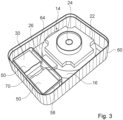
- Figure 3 shows a three-dimensional view of the interior of the energy storage external unit 40 without the cover.
- the view corresponds to the energy storage external unit 40 sunk into the ground, since only the above-ground area of the side wall 60 is shown, so that the underground interface is not visible.
- the rectangular gap 70 for heat recovery, through which the exhaust air flows between the stacked functional modules 50, is clearly visible.
- the funnel-shaped energy storage inlet 26, through which the exhaust air flows into the energy storage 14, projects into the gap 70.
- the walls of the energy storage inlet 26 extend to the corners of the functional modules 50, so that the exhaust air cannot flow past the energy storage 14, but into the
- the upper functional modules 50 are the heat pump 30 and the main connection module.
Landscapes
- Engineering & Computer Science (AREA)
- Chemical & Material Sciences (AREA)
- Combustion & Propulsion (AREA)
- Mechanical Engineering (AREA)
- General Engineering & Computer Science (AREA)
- Life Sciences & Earth Sciences (AREA)
- Sustainable Development (AREA)
- Central Heating Systems (AREA)
- Other Air-Conditioning Systems (AREA)
Claims (9)
- Appareil extérieur accumulateur d'énergie (40) d'un système (2) pour la climatisation d'espaces intérieurs (4) d'un bâtiment (6), dans lequel l'appareil extérieur accumulateur d'énergie (40) peut être disposé à l'extérieur du bâtiment (6), peut être partiellement enfoncé dans le sol et comprend- un accumulateur d'énergie (14) pour la transmission d'énergie et l'accumulation d'énergie, comportant un réservoir de liquide (16), un échangeur de chaleur à eau (18) dans le réservoir de liquide (16) et un échangeur de chaleur à air (22) au-dessus du réservoir de liquide (16),- une pompe à chaleur (30) qui est accouplée à l'échangeur de chaleur à eau (18) et à l'échangeur de chaleur à air (22),- un raccord pour air évacué (42) pour l'air évacué du bâtiment (6), lequel raccord est accouplé à l'accumulateur d'énergie (14),caractérisé en ce que le raccord pour air évacué (42) est également accouplé à la pompe à chaleur (30), de sorte que l'air évacué entrant en s'écoulant par le raccord pour air évacué (42) régule la température de la pompe à chaleur (30) au moins dans certaines zones, avant que l'air évacué ne s'écoule dans l'accumulateur d'énergie (14),dans lequel la pompe à chaleur (30) est conçue comme au moins un module fonctionnel (50) empilable et l'appareil extérieur accumulateur d'énergie (40) comprend au moins un autre module fonctionnel (50) empilable qui est conçu pour commander le chauffage, le refroidissement et/ou la ventilation dans le système, et les modules fonctionnels (50) sont disposés de telle sorte que l'air évacué s'écoule entre les modules fonctionnels (50) vers l'accumulateur d'énergie (14) et régule la température des modules fonctionnels (50).
- Appareil extérieur accumulateur d'énergie (40) selon la revendication 1, dans lequel la pompe à chaleur (30) est conçue de sorte que l'air évacué s'écoule devant et/ou à travers celle-ci et régule en particulier la température d'un circuit électrique de la pompe à chaleur (30).
- Appareil extérieur accumulateur d'énergie (40) selon la revendication 2, dans lequel la pompe à chaleur (30) est conçue de telle sorte que de la chaleur dissipée du circuit électrique assiste la régulation de la température.
- Appareil extérieur accumulateur d'énergie (40) selon l'une des revendications précédentes, dans lequel il y a un espace vertical (70) entre les modules fonctionnels (50), à travers lequel l'air évacué peut s'écouler vers l'accumulateur d'énergie (14).
- Appareil extérieur accumulateur d'énergie (40) selon l'une des revendications précédentes, dans lequel les modules fonctionnels (50) sont conçus de telle sorte que de la chaleur dissipée de circuits électriques dans les modules fonctionnels (50) assiste la régulation de la température.
- Appareil extérieur accumulateur d'énergie (40) selon l'une des revendications précédentes, lequel comprend une plaque de fond (64), un élément de recouvrement (66) et une paroi latérale périphérique (60) entre la plaque de fond (64) et l'élément de recouvrement (66).
- Appareil extérieur accumulateur d'énergie (40) selon l'une des revendications précédentes, dans lequel l'accumulateur d'énergie (14) présente un échangeur de chaleur à guidage d'air évacué (44) qui est conçu de sorte que l'air évacué est dirigé vers le réservoir de liquide (16) avant de s'écouler sur l'échangeur de chaleur à air (22).
- Appareil extérieur accumulateur d'énergie (40) selon l'une des revendications précédentes, dans lequel une cavité (46) conçue comme un réservoir d'eau potable et/ou d'eau non potable est disposée à l'intérieur du réservoir de liquide (16).
- Appareil extérieur accumulateur d'énergie (40) selon la revendication 10, dans lequel une pompe à eau, laquelle est conçue comme un module fonctionnel (50), est accouplée à la cavité (46).
Applications Claiming Priority (2)
| Application Number | Priority Date | Filing Date | Title |
|---|---|---|---|
| DE102021118417.7A DE102021118417A1 (de) | 2021-07-16 | 2021-07-16 | Energiespeicheraußengerät |
| PCT/EP2022/069919 WO2023285684A1 (fr) | 2021-07-16 | 2022-07-15 | Dispositif de stockage d'énergie extérieur |
Publications (3)
| Publication Number | Publication Date |
|---|---|
| EP4370837A1 EP4370837A1 (fr) | 2024-05-22 |
| EP4370837B1 true EP4370837B1 (fr) | 2025-05-07 |
| EP4370837C0 EP4370837C0 (fr) | 2025-05-07 |
Family
ID=82655183
Family Applications (1)
| Application Number | Title | Priority Date | Filing Date |
|---|---|---|---|
| EP22744473.4A Active EP4370837B1 (fr) | 2021-07-16 | 2022-07-15 | Appareil extérieur à accumulation d'énergie |
Country Status (10)
| Country | Link |
|---|---|
| US (1) | US20240318839A1 (fr) |
| EP (1) | EP4370837B1 (fr) |
| JP (1) | JP2024525788A (fr) |
| KR (1) | KR20240036605A (fr) |
| CN (1) | CN117616233A (fr) |
| AU (1) | AU2022309991A1 (fr) |
| CA (1) | CA3226417A1 (fr) |
| DE (1) | DE102021118417A1 (fr) |
| WO (1) | WO2023285684A1 (fr) |
| ZA (1) | ZA202400353B (fr) |
Families Citing this family (1)
| Publication number | Priority date | Publication date | Assignee | Title |
|---|---|---|---|---|
| DE202023105495U1 (de) | 2023-09-21 | 2025-01-08 | Smart Cube 360 GmbH | Wärmepumpenanordnung zur Beheizung eines Gebäudes |
Citations (1)
| Publication number | Priority date | Publication date | Assignee | Title |
|---|---|---|---|---|
| GB2247072A (en) * | 1990-06-13 | 1992-02-19 | Solmate Inc | Heating or cooling system |
Family Cites Families (46)
| Publication number | Priority date | Publication date | Assignee | Title |
|---|---|---|---|---|
| US2241060A (en) * | 1939-08-24 | 1941-05-06 | Gen Electric | Heat pump system |
| US2808494A (en) * | 1952-04-22 | 1957-10-01 | Telkes Maria | Apparatus for storing and releasing heat |
| US4139055A (en) * | 1976-06-17 | 1979-02-13 | Thomason Harry E | Solar heating (cooling) |
| US4237859A (en) * | 1977-04-25 | 1980-12-09 | Goettl Adam D | Thermal energy storage and utilization system |
| US4196719A (en) * | 1977-12-19 | 1980-04-08 | Solaray, Inc. | Heat storage means for solar heating system |
| US4350200A (en) * | 1978-07-24 | 1982-09-21 | Mcelwain John A | Solar energy collector and system |
| DE2952216C2 (de) * | 1979-12-22 | 1983-01-27 | Mannesmann AG, 4000 Düsseldorf | Verfahren und Vorrichtung zur Rückgewinnung und Wiederverwertung von Wärme aus den Abgasen metallurgischer Prozesse |
| GB2076139B (en) | 1980-04-03 | 1984-11-28 | Ti Creda Manufacturing Ltd | Heating systems |
| US4307778A (en) * | 1980-04-11 | 1981-12-29 | Carrier Corporation | Heat exchange unit having an internal support |
| US4452229A (en) * | 1981-11-13 | 1984-06-05 | Kim Powers | Thermal heat storage and cooling system |
| US4632180A (en) * | 1986-03-04 | 1986-12-30 | Lauderdale Robert J | Potable water heat exchanger |
| US5318101A (en) * | 1991-06-13 | 1994-06-07 | Kim Han Joong | Thermal accumulation type heating and cooling device using heat transfer medium |
| US5181552A (en) * | 1991-11-12 | 1993-01-26 | Eiermann Kenneth L | Method and apparatus for latent heat extraction |
| US5493871A (en) * | 1991-11-12 | 1996-02-27 | Eiermann; Kenneth L. | Method and apparatus for latent heat extraction |
| WO1995027873A1 (fr) * | 1994-04-08 | 1995-10-19 | Winston Mackelvie | Appareil servant a recuperer la chaleur des eaux de decharge |
| US5485879A (en) * | 1993-06-29 | 1996-01-23 | Bradford White Corporation | Combined water heater and heat exchanger |
| DE10321646A1 (de) * | 2002-06-03 | 2004-07-15 | Rubitherm Gmbh | Verfahren zur Wärme- und Kälteversorgung eines Raumes und Gebäude mit einer Mehrzahl mit einer Mehrzahl von Räumen |
| US7617697B2 (en) * | 2006-05-16 | 2009-11-17 | Mccaughan Michael | In-ground geothermal heat pump system |
| JP2009008318A (ja) * | 2007-06-27 | 2009-01-15 | Denso Corp | 排熱回収装置 |
| GB2455332A (en) * | 2007-12-05 | 2009-06-10 | Oxycom Beheer Bv | A combined heat exchange system supplying cooled air |
| DE202008002131U1 (de) | 2008-02-15 | 2009-06-25 | Henkenjohann, Walter | Wärmepumpenanlage |
| US7549418B1 (en) * | 2008-03-23 | 2009-06-23 | Moorman William E | Method and device for capture, storage and recirculation of heat energy |
| CA2628605C (fr) * | 2008-05-09 | 2011-06-28 | Huazi Lin | Pompe autonome pour liquide chauffe, circuit de chauffage de fluide, reservoir de stockage et systeme de chauffage de fluide utilisant celle-ci |
| WO2010095470A1 (fr) * | 2009-02-23 | 2010-08-26 | ダイキン工業株式会社 | Echangeur de chaleur, unité d'extérieur et dispositif de congélation |
| WO2010098610A2 (fr) * | 2009-02-26 | 2010-09-02 | 엘지전자 주식회사 | Système d'air conditionné et unité extérieure |
| US10422587B2 (en) * | 2009-11-05 | 2019-09-24 | Tai-Her Yang | Vertical fluid heat exchanger installed within natural thermal energy body |
| US8434509B2 (en) * | 2009-11-13 | 2013-05-07 | Eurotecnica Melamine Luxemburg | Tank for containing liquids |
| US8943848B2 (en) * | 2010-06-16 | 2015-02-03 | Reznor Llc | Integrated ventilation unit |
| SE535353C2 (sv) * | 2010-11-03 | 2012-07-03 | Climate Solutions Lnrj Ab | Värmeåtervinningsanläggning med en frånluftsvärmepump, en byggnad samt användning av anläggningen i byggnaden |
| DK2847442T3 (da) * | 2012-05-11 | 2019-10-14 | Vladan Petrovic | Langtidsvarmelager og fremgangsmåde til langvarig varmelagring af solenergi samt andre typer af energi med skiftende tilgængelighed |
| US20140144919A1 (en) * | 2012-11-27 | 2014-05-29 | Turki Awwad Al-Dhafiri | Insulated water tank |
| DE102015104909B3 (de) * | 2015-03-30 | 2016-09-29 | MBS Naturstromspeicher GmbH | Energiespeicher, Kraftwerksanlage mit Energiespeicher und Verfahren zum Betrieb desselben |
| CA2911796C (fr) * | 2015-11-12 | 2016-10-11 | Paul Zammit | Methode et systeme d'extraction de chaleur d'un gaz de combustion |
| DE102015121177A1 (de) * | 2015-12-04 | 2017-06-08 | Naturspeicher Gmbh | Verfahren und Vorrichtung zum Einbringen und zur Entnahme von Wärmeenergie in bzw. aus einem Gewässer |
| WO2017100768A1 (fr) * | 2015-12-12 | 2017-06-15 | Micro-Utilities, Inc. | Systèmes de stockage d'énergie passifs et procédés associés |
| EP3339790A1 (fr) * | 2016-12-21 | 2018-06-27 | L'air Liquide Societe Anonyme Pour L'etude Et L'exploitation Des Procedes Georges Claude | Échangeur de chaleur et procédé d'échange de chaleur l'utilisant |
| US12385654B2 (en) * | 2017-04-18 | 2025-08-12 | Nortek Air Solutions Canada, Inc. | Systems and methods for managing conditions in enclosed space |
| GB201815626D0 (en) * | 2018-09-25 | 2018-11-07 | Hughes Safety Showers Ltd | Water cooler |
| US11339977B2 (en) * | 2019-09-06 | 2022-05-24 | Carrier Corporation | Apparatus and method for providing adequate cooling inside an electrical equipment |
| AU2021208487A1 (en) * | 2020-01-13 | 2022-09-01 | Other Lab, Llc | Thermal storage system and method |
| DE102020119653B3 (de) | 2020-07-24 | 2021-07-15 | Envola GmbH | System zur Klimatisierung von Innenräumen eines Gebäudes |
| GB202101678D0 (en) * | 2021-02-07 | 2021-03-24 | Octopus Energy Ltd | Methods and systems and apparatus to support reduced energy and water usage |
| US11655996B2 (en) * | 2021-06-02 | 2023-05-23 | Lubnevskiy Konstantin Kazimirovich | Air to air heat pump with heat recovery function and exhaust air humidity for heating ventilation and air conditioning systems |
| AU2022356567B2 (en) * | 2021-09-30 | 2024-07-04 | Daikin Industries, Ltd. | Ventilation device and air-conditioning system |
| US12467696B2 (en) * | 2022-03-14 | 2025-11-11 | Timothy Patrick Cooper | Cooking apparatus with thermal energy storage system |
| US12474079B2 (en) * | 2023-10-23 | 2025-11-18 | Schlumberger Technology Corporation | Thermal system with exhaust heat exchanger |
-
2021
- 2021-07-16 DE DE102021118417.7A patent/DE102021118417A1/de active Pending
-
2022
- 2022-07-15 WO PCT/EP2022/069919 patent/WO2023285684A1/fr not_active Ceased
- 2022-07-15 CN CN202280048619.2A patent/CN117616233A/zh active Pending
- 2022-07-15 AU AU2022309991A patent/AU2022309991A1/en active Pending
- 2022-07-15 CA CA3226417A patent/CA3226417A1/fr active Pending
- 2022-07-15 KR KR1020247004851A patent/KR20240036605A/ko active Pending
- 2022-07-15 US US18/577,727 patent/US20240318839A1/en active Pending
- 2022-07-15 EP EP22744473.4A patent/EP4370837B1/fr active Active
- 2022-07-15 JP JP2024502002A patent/JP2024525788A/ja active Pending
-
2024
- 2024-01-10 ZA ZA2024/00353A patent/ZA202400353B/en unknown
Patent Citations (1)
| Publication number | Priority date | Publication date | Assignee | Title |
|---|---|---|---|---|
| GB2247072A (en) * | 1990-06-13 | 1992-02-19 | Solmate Inc | Heating or cooling system |
Also Published As
| Publication number | Publication date |
|---|---|
| DE102021118417A1 (de) | 2023-01-19 |
| CN117616233A (zh) | 2024-02-27 |
| JP2024525788A (ja) | 2024-07-12 |
| AU2022309991A1 (en) | 2024-01-25 |
| EP4370837A1 (fr) | 2024-05-22 |
| EP4370837C0 (fr) | 2025-05-07 |
| WO2023285684A1 (fr) | 2023-01-19 |
| ZA202400353B (en) | 2025-03-26 |
| CA3226417A1 (fr) | 2023-01-19 |
| US20240318839A1 (en) | 2024-09-26 |
| KR20240036605A (ko) | 2024-03-20 |
Similar Documents
| Publication | Publication Date | Title |
|---|---|---|
| EP2278231B1 (fr) | Installation de climatisation | |
| DE202013012529U1 (de) | Steuerung der Kühlung von Rechenzentren | |
| WO2024133883A1 (fr) | Dispositif extérieur de stockage d'énergie | |
| EP4370837B1 (fr) | Appareil extérieur à accumulation d'énergie | |
| EP3165838B1 (fr) | Dispositif d'aération de locaux | |
| DE202011110056U1 (de) | Klimaschrank | |
| EP0462402A1 (fr) | Sortie | |
| EP0041658A2 (fr) | Dispositif pour chauffer et refraîchir des pièces climatisées dans des résidences, des serres ou similaires | |
| DE102010013639A1 (de) | Kühlaggregat für Schaltschränke | |
| DE102013109702A1 (de) | Luftauslass sowie Verfahren zu dessen Umrüstung | |
| DE3834440A1 (de) | Vorrichtung mit waermerueckgewinnung zur be- und entlueftung von raeumen mit waermeueberschuss | |
| EP3370491A1 (fr) | Système de refroidissement destiné au refroidissement d'une armoire de serveur disposée dans un espace | |
| EP3399251A1 (fr) | Appareil de climatisation pour systèmes à double sol | |
| DE202009017577U1 (de) | Heiz- und Kühleinrichtungen mit einer Wärmepumpe | |
| EP4437280B1 (fr) | Système pour la climatisation d'un bâtiment | |
| DE102009053527B4 (de) | Klimaanlage | |
| DE6924985U (de) | Geraet zur vollklimatisierung und beckenwasserbeheizung von hallenschwimmbaedern | |
| DE10255172A1 (de) | Raumlüftungsgerät | |
| DE102015101022B3 (de) | Rechenzentrum | |
| DE29906375U1 (de) | Lüftungsanordnung für in Gebäuden untergebrachten Räumen | |
| DE4409500C2 (de) | Verfahren zur Klimatisierung von Schaltschränken o. dgl. | |
| AT512902A4 (de) | Freiluftschaltschrank | |
| DE202023106934U1 (de) | Ausseneinheitsanordnung von Wärmepumpen | |
| EP3763179A1 (fr) | Dispositif de refroidissement dans un bâtiment d'une unité technique fonctionnelle, en particulier pour refroidir un centre informatique | |
| DE19626923A1 (de) | Verfahren und Anlage zum Kühlen von Räumen |
Legal Events
| Date | Code | Title | Description |
|---|---|---|---|
| STAA | Information on the status of an ep patent application or granted ep patent |
Free format text: STATUS: UNKNOWN |
|
| STAA | Information on the status of an ep patent application or granted ep patent |
Free format text: STATUS: THE INTERNATIONAL PUBLICATION HAS BEEN MADE |
|
| PUAI | Public reference made under article 153(3) epc to a published international application that has entered the european phase |
Free format text: ORIGINAL CODE: 0009012 |
|
| STAA | Information on the status of an ep patent application or granted ep patent |
Free format text: STATUS: REQUEST FOR EXAMINATION WAS MADE |
|
| 17P | Request for examination filed |
Effective date: 20240216 |
|
| AK | Designated contracting states |
Kind code of ref document: A1 Designated state(s): AL AT BE BG CH CY CZ DE DK EE ES FI FR GB GR HR HU IE IS IT LI LT LU LV MC MK MT NL NO PL PT RO RS SE SI SK SM TR |
|
| DAV | Request for validation of the european patent (deleted) | ||
| DAX | Request for extension of the european patent (deleted) | ||
| GRAP | Despatch of communication of intention to grant a patent |
Free format text: ORIGINAL CODE: EPIDOSNIGR1 |
|
| STAA | Information on the status of an ep patent application or granted ep patent |
Free format text: STATUS: GRANT OF PATENT IS INTENDED |
|
| GRAS | Grant fee paid |
Free format text: ORIGINAL CODE: EPIDOSNIGR3 |
|
| INTG | Intention to grant announced |
Effective date: 20250227 |
|
| GRAA | (expected) grant |
Free format text: ORIGINAL CODE: 0009210 |
|
| STAA | Information on the status of an ep patent application or granted ep patent |
Free format text: STATUS: THE PATENT HAS BEEN GRANTED |
|
| AK | Designated contracting states |
Kind code of ref document: B1 Designated state(s): AL AT BE BG CH CY CZ DE DK EE ES FI FR GB GR HR HU IE IS IT LI LT LU LV MC MK MT NL NO PL PT RO RS SE SI SK SM TR |
|
| REG | Reference to a national code |
Ref country code: GB Ref legal event code: FG4D Free format text: NOT ENGLISH |
|
| REG | Reference to a national code |
Ref country code: CH Ref legal event code: EP |
|
| REG | Reference to a national code |
Ref country code: DE Ref legal event code: R096 Ref document number: 502022003900 Country of ref document: DE |
|
| REG | Reference to a national code |
Ref country code: IE Ref legal event code: FG4D Free format text: LANGUAGE OF EP DOCUMENT: GERMAN |
|
| U01 | Request for unitary effect filed |
Effective date: 20250606 |
|
| U07 | Unitary effect registered |
Designated state(s): AT BE BG DE DK EE FI FR IT LT LU LV MT NL PT RO SE SI Effective date: 20250616 |
|
| PG25 | Lapsed in a contracting state [announced via postgrant information from national office to epo] |
Ref country code: ES Free format text: LAPSE BECAUSE OF FAILURE TO SUBMIT A TRANSLATION OF THE DESCRIPTION OR TO PAY THE FEE WITHIN THE PRESCRIBED TIME-LIMIT Effective date: 20250507 |
|
| PG25 | Lapsed in a contracting state [announced via postgrant information from national office to epo] |
Ref country code: NO Free format text: LAPSE BECAUSE OF FAILURE TO SUBMIT A TRANSLATION OF THE DESCRIPTION OR TO PAY THE FEE WITHIN THE PRESCRIBED TIME-LIMIT Effective date: 20250807 Ref country code: GR Free format text: LAPSE BECAUSE OF FAILURE TO SUBMIT A TRANSLATION OF THE DESCRIPTION OR TO PAY THE FEE WITHIN THE PRESCRIBED TIME-LIMIT Effective date: 20250808 |
|
| PG25 | Lapsed in a contracting state [announced via postgrant information from national office to epo] |
Ref country code: PL Free format text: LAPSE BECAUSE OF FAILURE TO SUBMIT A TRANSLATION OF THE DESCRIPTION OR TO PAY THE FEE WITHIN THE PRESCRIBED TIME-LIMIT Effective date: 20250507 |
|
| PG25 | Lapsed in a contracting state [announced via postgrant information from national office to epo] |
Ref country code: HR Free format text: LAPSE BECAUSE OF FAILURE TO SUBMIT A TRANSLATION OF THE DESCRIPTION OR TO PAY THE FEE WITHIN THE PRESCRIBED TIME-LIMIT Effective date: 20250507 |
|
| PG25 | Lapsed in a contracting state [announced via postgrant information from national office to epo] |
Ref country code: RS Free format text: LAPSE BECAUSE OF FAILURE TO SUBMIT A TRANSLATION OF THE DESCRIPTION OR TO PAY THE FEE WITHIN THE PRESCRIBED TIME-LIMIT Effective date: 20250807 |
|
| U20 | Renewal fee for the european patent with unitary effect paid |
Year of fee payment: 4 Effective date: 20250916 |
|
| PG25 | Lapsed in a contracting state [announced via postgrant information from national office to epo] |
Ref country code: IS Free format text: LAPSE BECAUSE OF FAILURE TO SUBMIT A TRANSLATION OF THE DESCRIPTION OR TO PAY THE FEE WITHIN THE PRESCRIBED TIME-LIMIT Effective date: 20250907 |
|
| PG25 | Lapsed in a contracting state [announced via postgrant information from national office to epo] |
Ref country code: SM Free format text: LAPSE BECAUSE OF FAILURE TO SUBMIT A TRANSLATION OF THE DESCRIPTION OR TO PAY THE FEE WITHIN THE PRESCRIBED TIME-LIMIT Effective date: 20250507 |
|
| PG25 | Lapsed in a contracting state [announced via postgrant information from national office to epo] |
Ref country code: CZ Free format text: LAPSE BECAUSE OF FAILURE TO SUBMIT A TRANSLATION OF THE DESCRIPTION OR TO PAY THE FEE WITHIN THE PRESCRIBED TIME-LIMIT Effective date: 20250507 |
|
| PG25 | Lapsed in a contracting state [announced via postgrant information from national office to epo] |
Ref country code: SK Free format text: LAPSE BECAUSE OF FAILURE TO SUBMIT A TRANSLATION OF THE DESCRIPTION OR TO PAY THE FEE WITHIN THE PRESCRIBED TIME-LIMIT Effective date: 20250507 |
|
| REG | Reference to a national code |
Ref country code: CH Ref legal event code: H13 Free format text: ST27 STATUS EVENT CODE: U-0-0-H10-H13 (AS PROVIDED BY THE NATIONAL OFFICE) Effective date: 20260224 |
|
| PLBE | No opposition filed within time limit |
Free format text: ORIGINAL CODE: 0009261 |
|
| STAA | Information on the status of an ep patent application or granted ep patent |
Free format text: STATUS: NO OPPOSITION FILED WITHIN TIME LIMIT |
|
| REG | Reference to a national code |
Ref country code: CH Ref legal event code: L10 Free format text: ST27 STATUS EVENT CODE: U-0-0-L10-L00 (AS PROVIDED BY THE NATIONAL OFFICE) Effective date: 20260318 |
|
| 26N | No opposition filed |
Effective date: 20260210 |
|
| PG25 | Lapsed in a contracting state [announced via postgrant information from national office to epo] |
Ref country code: CH Free format text: LAPSE BECAUSE OF NON-PAYMENT OF DUE FEES Effective date: 20250731 |