EP4370845B1 - Gleichrichter für einen kältemitteldampferzeuger für absorptionswärmemaschinen und generator umfassend einen solchen gleichrichter - Google Patents
Gleichrichter für einen kältemitteldampferzeuger für absorptionswärmemaschinen und generator umfassend einen solchen gleichrichter Download PDFInfo
- Publication number
- EP4370845B1 EP4370845B1 EP22741293.9A EP22741293A EP4370845B1 EP 4370845 B1 EP4370845 B1 EP 4370845B1 EP 22741293 A EP22741293 A EP 22741293A EP 4370845 B1 EP4370845 B1 EP 4370845B1
- Authority
- EP
- European Patent Office
- Prior art keywords
- rectifier
- tubes
- flows
- refrigerant
- generator
- Prior art date
- Legal status (The legal status is an assumption and is not a legal conclusion. Google has not performed a legal analysis and makes no representation as to the accuracy of the status listed.)
- Active
Links
Images


Classifications
-
- F—MECHANICAL ENGINEERING; LIGHTING; HEATING; WEAPONS; BLASTING
- F25—REFRIGERATION OR COOLING; COMBINED HEATING AND REFRIGERATION SYSTEMS; HEAT PUMP SYSTEMS; MANUFACTURE OR STORAGE OF ICE; LIQUEFACTION SOLIDIFICATION OF GASES
- F25B—REFRIGERATION MACHINES, PLANTS OR SYSTEMS; COMBINED HEATING AND REFRIGERATION SYSTEMS; HEAT PUMP SYSTEMS
- F25B33/00—Boilers; Analysers; Rectifiers
-
- F—MECHANICAL ENGINEERING; LIGHTING; HEATING; WEAPONS; BLASTING
- F25—REFRIGERATION OR COOLING; COMBINED HEATING AND REFRIGERATION SYSTEMS; HEAT PUMP SYSTEMS; MANUFACTURE OR STORAGE OF ICE; LIQUEFACTION SOLIDIFICATION OF GASES
- F25B—REFRIGERATION MACHINES, PLANTS OR SYSTEMS; COMBINED HEATING AND REFRIGERATION SYSTEMS; HEAT PUMP SYSTEMS
- F25B2333/00—Details of boilers; Analysers; Rectifiers
- F25B2333/006—Details of boilers; Analysers; Rectifiers the generator or boiler having a rectifier
-
- Y—GENERAL TAGGING OF NEW TECHNOLOGICAL DEVELOPMENTS; GENERAL TAGGING OF CROSS-SECTIONAL TECHNOLOGIES SPANNING OVER SEVERAL SECTIONS OF THE IPC; TECHNICAL SUBJECTS COVERED BY FORMER USPC CROSS-REFERENCE ART COLLECTIONS [XRACs] AND DIGESTS
- Y02—TECHNOLOGIES OR APPLICATIONS FOR MITIGATION OR ADAPTATION AGAINST CLIMATE CHANGE
- Y02A—TECHNOLOGIES FOR ADAPTATION TO CLIMATE CHANGE
- Y02A30/00—Adapting or protecting infrastructure or their operation
- Y02A30/27—Relating to heating, ventilation or air conditioning [HVAC] technologies
Definitions
- the present invention relates to a rectifier for a generator of refrigerant vapour for thermal machines based on an absorption cycle, and to a generator comprising such a rectifier.
- absorption thermal machines typically chillers or heat pumps, are thermal machines that exploit the capability of a substance, whether liquid or solid, to 'absorb' a second chemical species in the gaseous state; for example an unsaturated solution of water and ammonia can absorb ammonia vapour.
- thermochemical compressor the refrigerant vapour at low-pressure is not compressed with an electrically powered mechanical compressor, but absorbed by the absorbent solution, which is then pumped at high pressure with reduced power consumption and sent to a generator or desorber. In the generator, the solution is heated to boiling, resulting in the production of high-pressure refrigerant vapour necessary for realizing the refrigeration cycle.
- the refrigerant-rich, high-pressure vapour is sent to a condenser and then, passing through an evaporator, returns to an absorber.
- the hot, depleted solution exiting the generator flows into a solution heat exchanger (SHX), which has the purpose of recovering the heat of the depleted solution by preheating the refrigerant-rich solution pumped towards the generator, which then passes through a thermal expansion valve and also returns to the absorber, where it absorbs the refrigerant vapour.
- SHX solution heat exchanger
- the refrigerant vapour is generated in the boiler of the generator, in which the refrigerant-rich solution is kept boiling by the heat supplied by a high-temperature source, e.g. a burner.
- the generator When the vapour pressure of the absorbent of the solution is relatively high, e.g. in the case of water-ammonia thermal machines, the generator also comprises a rectifier, which serves to reduce the concentration of absorber in the vapour flow produced by the boiler by mass exchange with the solution rich of refrigerant entering the generator and partial condensation of the vapour itself, and thus to increase the refrigerant content of the high-pressure vapour exiting the generator itself.
- a rectifier which serves to reduce the concentration of absorber in the vapour flow produced by the boiler by mass exchange with the solution rich of refrigerant entering the generator and partial condensation of the vapour itself, and thus to increase the refrigerant content of the high-pressure vapour exiting the generator itself.
- the rectifier commonly comprises a stripping column or stripper or analyser, in which the refrigerant vapour is stripped from the refrigerant-rich solution by means of direct contact with the hot vapour flows produced by the boiler, as well as a dephlegmator or partial condenser that allows for a further increase in the purity of the refrigerant contained in the vapour flows produced.
- the generator of an absorption thermal machine in particular an absorption heat pump, must manage significant power variations in input to the burner, significant variations in the flow rate and level of the solution in the various sections, and significant variations of the temperature and internal pressure. All of this while ensuring complete protection from leakages to the outside, particularly when ammonia is used, with no maintenance over tens of thousands of hours of operation, and without adversely affecting the efficiency of the heat and mass exchanges in the various components.
- the components of the rectifier are important in terms of the construction and overall performance of the generator.
- a typical solution for the stripper or analyser provides for the use of a plate column, as is typical in distillation processes, sometimes with the insertion of a filler, e.g. metal raschig rings or ceramic saddles.
- a filler e.g. metal raschig rings or ceramic saddles.
- Ad hoc solutions such as the use of a triple coil described in patent US 4,106,309 A , or plate columns that include the circuit of the refrigerant-depleted solution in the plates themselves, result in an increase of the internal heat recovery, but increase the complexity and costs of the stripping column.
- the dephlegmator which is commonly arranged above the analyser, uses a coolant to which the vapour flows passing through it yield the condensation heat.
- this heat may be variously reintroduced into the thermodynamic cycle; currently, three fluids are usually used: air, water, or the same solution rich of refrigerant is used to generate the refrigerant vapour, typically a solution of water and ammonia directed at the inlet of the generator.
- the most common practice is to cool the vapour flow in the dephlegmator by means of the refrigerant-rich solution pumped in the generator.
- the energy recovery in this case is greater than the aforementioned cases, because the enthalpy of the condensation of the vapour becomes the enthalpy of the rich solution that must be brought to a boil in the generator, and thus it does not affect the overall COP of the thermal machine.
- the thermal power of absorption machines results from evaporation, condensation, and absorption processes characterised by very high specific enthalpies; thus, the flow rate of the rich solution, which is a vector of the refrigerant, is small, on the order of a few kg/h per kW of thermal power in the case of heat pumps.
- the small flow rate implies a low thermal capacity; the solution heats up rapidly in the dephlegmator, and the mean difference in temperature between the flows, which is the motor of the heat exchange, is reduced.
- the low flow rate also results in very low heat exchange coefficients between the solution and the surfaces of the dephlegmator.
- Another possible way of obviating low heat exchange coefficients is to reduce the flow passage section of the rich solution in order to increase its speed and turbulence.
- both solutions result in an increased pressure loss, which is particularly critical where, as is common with small machines, the pump of the solution is an alternative volumetric pump, for example a membrane-based pump.
- heating the rich solution in the dephlegmator results in reduced cooling capacity of the depleted solution in the so-called solution-cooled absorbers (SCA) in the case of machines based on GAX (generator-absorber heat exchange) or SHX (in the case of single-effect cycles) cycles, thus significantly reducing the benefit of the internal recovery obtained.
- SCA solution-cooled absorbers
- the dephlegmator is realized as a vertical component inside the head of the generator, thus increasing its height and thus the overall dimensions of the machine, in particular if the exchange surfaces are important due to the limited turbulence of the rich solution and/or to the limited mean temperature difference between the vapour flow to be condensed and the rich solution.
- the dephlegmator is commonly a separate component from the generator, extending horizontally or inclined and has a siphon through which the condensation flows back into the generator.
- vapour bypass i.e. a certain amount of vapour does not come into contact with the cold surfaces of the dephlegmator, i.e. the surfaces that transfer heat to the coolant, and thus does not undergo the intended partial condensation.
- the main scope of the present invention is to provide a rectifier for a generator of refrigerant vapour for absorption thermal machines that is capable of at least partially mitigating one or more of the aforementioned drawbacks.
- one object of the present invention is to provide a rectifier for a generator of refrigerant vapour for absorption thermal machines that allows obtaining vapour flows having an adequate degree of refrigerant purity, according to a structure that is compact, functionally efficient, and can be realized at relatively low cost.
- Another object of the present invention is that of providing a rectifier allowing for adequate exploitation of the auto-analysis effect and minimising, if not completely avoiding, any bypass by the vapour flows passing through it.
- a further object of the present invention is to provide a rectifier allowing for optimal control of the purity of the refrigerant over the entire broad operating range of the heat pump, with the possibility of limiting purity in favour of reduced maximum pressure in the case of hot water production.
- Figures 1-6 and 9 show embodiments being useful for understanding the invention, which are outside the subject-matter of the claims.
- Figures 7 and 8 show embodiments according to the present invention, which disclose a rectifier according to claim 1.
- transversal or “transversally” are used herein they are to be understood as including a direction that is not parallel to the reference part or parts or direction(s)/ axis to which they refer; and perpendicularity is to be considered one specific case of transversal direction.
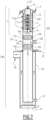
- Fig. 7 and 8 are schematic representations of two possible exemplary embodiments of a vapour generator 200 in which a rectifier according to the invention (indicated as a whole by the reference number 100) may be used.
- the generator 200 extends vertically along a substantially vertical reference axis Y, and, at its bottom, there is provided a boiler, schematically represented by the reference numeral 50, which is suitable for boiling a liquid solution containing an absorbent substance and an absorbed refrigerant substance so as to generate vapour flows containing the refrigerant.
- a solution comprising water and ammonia may be inserted into the boiler 50 via the conduit 52 and boiled by means of a burner 51, and then exit the boiler 50 via the conduit 53; the hot fumes generated by the burner 51, on the other hand, may exit via the conduit 54.
- the boiler 50 may be of any embodiment and operating modality known in the prior art and/or can be easily realized by a person skilled in the art, and, in any case, are not relevant for the purposes of describing the rectifier 100 according to the invention; as such, they are not described in further detail herein.
- vapour flows rich of refrigerant generated, indicated by the arrows V in figures 7 and 8 , rise towards the top of the generator 200 for appropriate modification by the rectifier (100) according to claim 1.
- the rectifier 100 has a modular configuration in which more or fewer rectification stages are applied to the vapour flows V depending on the number of inlets, corresponding to different solution temperature levels, that are provided in the generator for the rich solution.
- the rectifier 100 comprises at least one casing 101 that extends along a substantially vertical reference axis X; when the rectifier is used in the generator 200, the vertical reference axis X preferably substantially coincides with the axis Y along which the generator 200 itself extends vertically.
- At least one first transverse conduit 102 suited to allow the introduction of flows of the liquid solution L to be boiled in the subjacent boiler 50 is used in addition to the first conduit 52; according to the invention, the temperature of the liquid solution introduced via the conduit 102 is less than that of the solution introduced via the conduit 52.
- the rectifier 100 additionally comprises at least one first body, one exemplary embodiment of which is shown in fig. 6 and indicated therein by the reference numeral 105, which consists of an open-cell ceramic foam, which is contained in the casing 101 below the conduit 102.
- the first body 105 is arranged along the casing 101 so as to be traversed in one direction by flows of the liquid solution L to be boiled, introduced via the conduit 102, which descend due to gravity towards the boiler 50 and wet the surfaces of the first body 105 itself, and in particular those of its open cells.
- the first body 105 is traversed by flows of vapour V generated by boiling, which rise up from the boiler 50 as a countercurrent to the solution L and exchange heat with the solution itself that is wetting the surfaces of the first body 105, causing simultaneous evaporation of refrigerant from the solution L and condensation of at least some of the absorbent substance contained in the rising vapour flows V.
- the rectifier 100 advantageously comprises at least one second body, also consisting of an open-cell ceramic foam, that is substantially equivalent to the first body 105 and is indicated in fig. 6 - 8 by the reference numeral 110.
- the second body 110 is contained in the casing 101, above and spaced apart from the first body 105, and is advantageously contained within the casing above the conduit 102, which opens into the area between the two bodies 105 and 110 themselves.
- the second body 110 may be contained in the casing above the conduit 102; in the embodiment of fig. 7 , no other inlets are provided for the flows of the rich solution L above the conduit 102 itself.
- the second body 110 is traversed from top to bottom only by the backflow of condensate, indicated by the arrows Vc, produced by the heat exchange between the rising vapours V and a coolant, indicated by the arrows F, used in the dephlegmator.
- This condensate backflow wets the surfaces of the open cells of the body 110; in this way, the rising vapour flows traverse the second body 110 as a countercurrent to the condensate backflow and exchanges heat with the backflow itself and the surfaces wet by it, generating new flows of vapour that contain refrigerant.
- Vc condensate
- F coolant
- the rectifier 100 comprises another transverse conduit 104, below which the second body 110 is positioned; in this case, the conduit 104 constitutes another inlet for the flow of rich solution L at a lower temperature than that of the flow entering via the second conduit 102.
- the second body 110 is also traversed by flows of the liquid solution L to be boiled, which are introduced via the conduit 104, and descend due to gravity towards the boiler 50, wetting the surfaces of the second body 110 itself, and in particular those of its open cells.
- the second body 110 is traversed by vapour flows V generated by boiling, which rise from the boiler 50 to first traverse the first body 105 and the second body 110 itself, and then exchange heat with the solution itself that wets the surfaces of the second body 110, causing simultaneous evaporation of refrigerant from the solution L introduced via the third conduit 104 and condensation of at least some more of the absorbent substance contained in the rising vapour flows V.
- the first body 105 and the second body 110 have a shape geometrically conjugated with the inner surface of the casing 101 and are connected in a fluid-tight fashion along the inner walls of the casing itself 101, for example by means of PTFE rings or tapes, indicated schematically in fig. 7 and 8 by reference numeral 106, which are arranged at least along the edges of the bodies 105 and 110 and the adjacent surfaces of the inner walls of the casing 101.
- the casing 101 has a substantially cylindrical configuration extending along the substantially vertical reference axis X, and the first body 105 and second body 110 each are cylindrical in form with a diameter substantially equal or slightly smaller than the internal diameter of the casing 101, within the tolerance strictly required to ensure their insertion and for the insertion of the sealing elements 106.
- the first and second bodies 105, 110 are for example made of aluminium oxide-based open cell ceramic foam, which combines extremely low cost with increased chemical inertness, resistance to high temperatures, and good wettability.
- the rectifier 100 further comprises a dephlegmator (indicated as a whole by reference numeral 1), which is suitable to carry out a further condensation of the absorbent remaining in the vapours rectified via the first body 105 and, if applicable, the second body 110, so as to obtain even higher purity of the refrigerant contained in the rectified vapours.
- a dephlegmator indicated as a whole by reference numeral 1
- the dephlegmator 1 comprises at least a plurality of tubes 2 for circulating the coolant fluid F, which is suitable for cooling the vapour flows V rising through the dephlegmator 1 by heat exchange.
- each tube 2 comprises at least one rectilinear portion 3 extending longitudinally in a direction substantially parallel to the reference axis X.
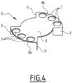
- the dephlegmator 1 comprises at least a plurality of plates 6, which, as shown for example in figures 2 and 5 , are stacked up in sequence one on top of the other along the reference axis X.
- each plate 6 comprises a plurality of through holes 7 that are each traversed by a corresponding rectilinear portion 3 of a tube 2 of the plurality of tubes, and the plates 6 are suitably configured and mutually arranged so as to convey at least part of the vapour flows V traversing the dephlegmator 1 along the outer walls of the longitudinal portions 3 of one or more tubes 2 of the plurality of tubes 2.
- each plate 6 is rotated of a predefined angle ⁇ relative to the immediately subjacent plate 6 in a transversal plane, in particular perpendicular, to the reference axis X.
- the angle of rotation ⁇ is between 85° and 95°, preferably substantially equal to 90°.
- this angle of rotation ⁇ may be taken to be in the clockwise or anticlockwise direction; for example starting from the bottom in fig. 2 , the second plate 6 is rotated 90° clockwise/anticlockwise relative to the first plate 6, whilst the third plate 6 is rotated 90° clockwise/anticlockwise relative to the second plate 6, etc.
- the plates 6 are substantially identical.
- FIG 4 An example of a plate 6 is shown in figure 4 , and comprises a substantially flat base 8 extending in a transversal plane, in particular substantially perpendicular to the reference axis X, and has, for instance, a substantially circular planform, on which the plurality of through holes 7 is formed; additionally, each plate 6 has one or more side walls 9 extending transversely from the base 8 in a direction substantially parallel to the reference axis X.
- the plurality of through holes 7 comprises a first series of through holes 7 adjacent to one another and arranged at a first edge 8a of the base 8 and a second series of through holes 7 adjacent to one another and arranged at a second edge 8b of the base 8 that is opposite the first edge 8a relative to the reference axis X.
- the one or more side walls 9 comprise, for example, a first and a second side walls 9 extending transversely from the base 8 in a direction substantially parallel to the reference axis X with the first series of through holes 7 arranged between them, and a third and fourth side walls 9 extending transversely from the base 8 in a direction substantially parallel to the reference axis X with the second series of through holes 7 arranged between them.
- each plate 6 is made from a steel sheet that is perforated and then appropriately cut along the two opposite unperforated edges, with the side walls 9 being obtained by bending.
- the plates 6 may be made of any other suitable material, e.g. of technopolymers that are resistant to the operating temperatures of the dephlegmator.
- the plates 6 are stacked with the walls 9 acting as spacers between the plates and as supports on the base 8 of the immediately subjacent plate 6.
- each tube 2 comprises a substantially U- or C-shaped body having a first and a second rectilinear portions 3 extending longitudinally along said direction substantially parallel to the reference axis X, and a central portion 4 which connects the respective first and second rectilinear portions 3 at their first end 3a.
- the plurality of U- or C-shaped tubes 2 comprises a first series of tubes 2a that are arranged side by side to each other, and a second series of tubes 2b that are arranged side by side with the respective first and second rectilinear portions 3 substantially parallel to one another; the tubes 2a of the first series of tubes 2 are inserted transversely within the concavity defined by the U- or C-shaped bodies of the tubes 2 of the second series of tubes 2b, with their curved parts arranged above the corresponding curved parts of the tubes of the second series 2b.
- the tubes of the two series 2a and 2b are arranged substantially perpendicularly to one another, with the former (tubes 2a) partially inserted into the space defined by the latter (tubes 2b), thus providing a solution that is compact in design and extends vertically.
- the dephlegmator 1 it is possible to use more than two series of tubes 2, e.g. three series of tubes arranged at 60° to one another; accordingly, the plates 6 may be provided with three series of through holes, and may be arranged rotated at 60° to one another.
- the dephlegmator 1 further comprises a plate 10, shown in detail in fig. 3 , e.g. made of steel.
- the plate 10 which extends, for example substantially planarly in a tranversal, in particular perpendicular, plane relative to the reference axis X, and has a substantially circular planform with the axis X passing through the centre, has a plurality of through holes 11 arranged sequentially at a peripheral edge 12 of the plate 10 itself.
- the dephlegmator 1 may comprise a bottom cover or conveyor tube 13, shown in fig. 3 , which is affixed, e.g. welded, to the plate 10 in a substantially central position, and is suited to be connected to a condenser external to the generator 200, towards which the rectified vapour flows V R that have passed through the dephlegmator 1 and have been cooled by it and at least partially purified by the absorbent substance are to be conveyed.
- the plates 6 are stacked with the vertical walls 9 of each plate supported on the base 8 of the subjacent plate 6; the fact that each plate 6 is rotated relative to the subjacent plate 6 at the angle of rotation ⁇ , e.g. 90°, makes it possible to have an alternating sequence of plates and, ultimately, to obtain four mutually aligned series of through holes 7, of which two series of through holes 7 are those of the plates 6 arranged in the stack in even-numbered positions, and the other two series of through holes 7 consist of the holes of the plates 6 arranged in the stack in odd-numbered positions.
- ⁇ e.g. 90°
- the tubes 2 are simply inserted into the respective holes 7 of the plates 6.
- each tube 2 of the first series of tubes 2a is coupled with the stack of plates 6 by inserting the respective rectilinear portions 3, each into a corresponding series of vertically aligned holes 7, more specifically in those of the plates 6 in the odd-numbered positions in the stack;
- the tubes of the second series of tubes 2b are coupled with the stack of plates 6 by inserting the respective rectilinear portions 3, each into a corresponding series of vertically aligned holes 7, more specifically in those of the plates 6 in the even-numbered positions in the stack.
- the plates 6 can be assembled together and with the tubes 2, without any need to weld the parts together.
- the plate 10 is connected to the tubes 2; in particular, the plate 10 is welded to each tube 2 at the second free end 3b of its first and second rectilinear portions.
- each tube 2 is associated with two respective peripheral holes 11 suitable for one to allow the coolant fluid F to enter each tube 2 and the other to flow out of it, respectively.
- the assembly thus obtained may be inserted into the casing 101, for example by positioning the perforated plate 10, pre-welded to the tubes 2, abutting the upper surface of the casing 101, and then affixing it in a suitable fashion, e.g. by welding.
- the rectifier 100 thus obtained may be marketed separately or installed directly in a generator 200, for example by connecting its casing 101 to the subjacent part containing the boiler 50.
- the vapour generated by the boiler 50 by boiling the initial solution, indicated by the arrows V rises through the stripper or analyser, passing through the first body 105 and, if applicable, the second body 110.
- the solution L inserted through the conduit 102 flows downward, wetting the surface of the ceramic foam and coming into contact with the rising vapour V, so as to maximise the exchange surface and obtain continuous distillation.
- the vapours thus initially rectified rise to reach the dephlegmator 1 if used.
- the flow of coolant fluid F for example the water to be heated by the heat pump in which the dephlegmator is installed, enters the tubes 2 of the dephlegmator 1 via the upper plate 10, and first flows as a countercurrent to, and then in co-current together with, the rising vapour V flow.
- This atypical configuration has a very slight adverse effect on the efficiency of the dephlegmator 1, because the flow rate of the fluid F flow, and in particular of water, is elevated compared to the power exchanged in the dephlegmator 1, and its temperature variation whilst passing through the dephlegmator 1 is insignificant compared to the mean temperature difference between the coolant fluid and the vapour V flow.
- the plates 6 convey the vapour V along the outer surface of the tubes 2, and, in particular, along the respective rectilinear portions 3, where, due to the heat exchange with the coolant fluid F, the vapour V is further cooled, resulting in an additional condensation of the absorbent, e.g. water, contained in the vapour flows V.
- the absorbent e.g. water
- the purity of the refrigerant contained in the rectified vapour flows (arrow V R ) that have passed through the dephlegmator 1 and leave the generator 200 via the conveyor tube 13 is advantageously increased.
- the plates 6 cause them restirring continuously to minimize any bypass, thus preventing, or at least minimising, the possibility that some of the vapour V bypasses the dephlegmator 1 without getting into contact with the tubes 2 and without transferring heat to the coolant fluid F.
- this condensate reflux wets, or contributes to the wetting of, the surface of the ceramic foam of the second body 110, and thereafter of the first body 105, thus increasing the efficacy of the heat exchange carried out therein.
- the rectifier 100 further comprises a jacket 15 arranged on the outside of the plurality of tubes 2 and is in fluid communication with the inlets and outlets 3b of the tubes 2 themselves.
- This jacket 15 is suited to circulate inside it flows of coolant fluid F, e.g. water, exiting the tubes 2.
- coolant fluid F e.g. water
- This configuration allows increasing the heat exchange surface area between water and vapour, thus allowing for further reductions in the height of the dephlegmator 1, and thus of the generator 200 as a whole, with equal performance.
- the outer jacket 15 is shown installed on the outside of at least the casing 101 that accommodates the other components of the dephlegmator 1, thus cooling its walls after flowing in the tubes 2.
- the rectifier 100 advantageously also comprises control means suitable for regulating the flow rate of the water introduced into the plurality of tubes 2.
- a bypass branch 16 is arranged parallel to the dephlegmator 1, because the full flow rate of water must be ensured, and the flow of water is divided between the condenser 205 and the absorber 210 of the absorption machine in which the generator 200 is used so as to minimise pressure losses.
- control means comprises for example a proportional mixing valve 17 installed downstream of the tubes 2 of the dephlegmator 1, and is actuated under the control of a suitable control unit 18.
- the actuation of the mixing valve 17 allows modifying, in a regulated way, the total flow rate of the water flowing through the dephlegmator 1; thus, the capacity of the dephlegmator 1 is controlled, and, in particular, the rectification process is regulated, thus ultimately varying the purity of the refrigerant vapour, and, with it, the pressure in the condenser.
- the flow rate of the water flowing within it is reduced, thus reducing both the mean temperature difference between the water and the vapour V and the heat exchange coefficient between the water and the tubes 2.
- a refrigerant vapour is obtained that is less pure and condenses at lower pressures.
- This entails a reduction in the performance of the evaporator, but in the case of producing high-temperature hot water, e.g. for the production of sanitary hot water (SHW), this reduction in the maximum operating pressure of the heat pump results in significant benefits design, cost, and useful life, in particular in the case of water-ammonia heat pumps, where the production of hot water at 70°C may result in pressures above 30 absolute bar in the condenser.
- SHW sanitary hot water
- this regulation is carried out so as to ensure a minimum flow rate in any case, in order to avoid the water boiling in the dephlegmator, with the resultant adverse fluid-dynamic effects (cavitation) in the water circuit.
- the rectifier 100 achieves the indicated scope and objectives since it allows obtaining, in a highly efficient way, rectified vapour with an adequate refrigerant purity and according to a compact, highly efficient structure that can be realized at relatively low cost.
- the rectifier 100 according to the invention may be made with more rectification stages or phases depending on the applications and the number of inlets for liquid solution at various temperature levels, and, in particular, on the desired degree of purity, and it may be advantageously used in generators of refrigerant vapour for absorption thermal machines.
- another object of this invention is a generator 200 of vapour containing a refrigerant for absorption thermal machines, which includes a boiler 50 arranged at the base of the generator 200 and suitable for boiling a liquid solution L comprising at least one absorbent substance and one refrigerant substance absorbed so as to generate vapour flows V containing said absorbed refrigerant substance and possibly a percentage of absorbent substance.
- a generator 200 is characterised by the fact that it further comprises at least one rectifier 100 according to claim 1, which is arranged above said boiler 50 and is adapted to be crossed by and modify, in particular increase, the percentage of the refrigerant substance present in the vapour flows V generated by boiling.
- the present invention also includes an absorption thermal machines, e.g. a heat pump or chiller, wherein it comprises such a generator 200 and at least one rectifier 100 according to one or more of the appended claims.
- absorption thermal machines e.g. a heat pump or chiller
- the housing 101 may be made of several separate parts that are assembled together, e.g. a first part to hold only the open cell ceramic foam body(ies) constituting the stripper/analyser, and a second part to hold the components of the dephlegmator 1, when used; the solution employed may consist of components other than water and ammonia; the second body 110 may be made of different ceramic materials, e.g. using silicon carbide; depending on the thermodynamic cycle carried out by the thermal machine, a different number of inlet conduits for the liquid solution L for boiling may be used, etc.
Landscapes
- Engineering & Computer Science (AREA)
- Power Engineering (AREA)
- Physics & Mathematics (AREA)
- Mechanical Engineering (AREA)
- Thermal Sciences (AREA)
- General Engineering & Computer Science (AREA)
- Sorption Type Refrigeration Machines (AREA)
- Vaporization, Distillation, Condensation, Sublimation, And Cold Traps (AREA)
Claims (16)
- Gleichrichter (100) für einen Kältemitteldampferzeuger (200), wobei der Gleichrichter angepasst ist, um den Prozentsatz einer Kältemittelsubstanz zu modifizieren, die in Dampfströmen (V) vorhanden ist, die durch Sieden einer flüssigen Lösung (L) erzeugt werden, umfassend mindestens eine absorbierende Substanz und die absorbierte Kältemittelsubstanz, und wobei er mindestens Folgendes umfasst:- ein Gehäuse (101), das sich entlang einer im Wesentlichen vertikalen Bezugsachse (X) erstreckt und mindestens einen ersten Querkanal (102) beinhaltet, der konstruiert ist, um die Einführung von Strömen der zu siedenden flüssigen Lösung (L) zu ermöglichen;- mindestens einen ersten Körper (105), der in dem Gehäuse (101) unter dem ersten Kanal (102) untergebracht ist, um von Strömen der zu siedenden flüssigen Lösung (L), die nach unten fließen und seine Oberflächen benetzen, und von Dampfströmen (V), die durch das Kochen erzeugt werden und nach oben fließen, durch Wärmeaustausch mit der Lösung an sich, die die Oberflächen des ersten Körpers (105) benetzt, durchströmt zu werden, was gleichzeitig eine Verdampfung des Kältemittelss aus der flüssigen Lösung (L) und eine Kondensation von mindestens einem Teil der absorbierenden Substanz, die in den nach oben gerichteten Dampfströmen (V) enthalten ist, bewirkt, dadurch gekennzeichnet, dass der erste Körper (105) aus einem offenzelligen Keramikschaum besteht.
- Gleichrichter (100) nach Anspruch 1, ferner umfassend einen zweiten Körper (110), der aus einem offenzelligen Keramikschaum besteht und in dem Gehäuse (101) untergebracht ist, das von dem ersten Körper (105) beabstandet ist und über dem ersten Kanal (102) angeordnet ist.
- Gleichrichter (100) nach Anspruch 2, ferner umfassend einen weiteren Kanal (104), der über dem zweiten Körper (110) angeordnet und angepasst ist, um die Einleitung weiterer Ströme der zu siedenden flüssigen Lösung (L) mit einer niedrigeren Temperatur als die Ströme der zu siedenden flüssigen Lösung (L), die aus dem ersten Kanal (102) eintreten, zu ermöglichen.
- Gleichrichter (100) nach einem oder mehreren der vorherigen Ansprüche, wobei der erste Körper (105) und/oder der zweite Körper (110) eine Form aufweisen, die geometrisch mit der Innenfläche des Gehäuses (101) konjugiert ist, und fluiddicht entlang der Innenwände des Gehäuses an sich (101) verbunden sind.
- Gleichrichter (100) nach Anspruch 4, wobei das Gehäuse (101) eine im Wesentlichen zylindrische Konfiguration aufweist, die sich entlang der im Wesentlichen vertikalen Bezugsachse (X) erstreckt, und wobei der erste und der zweite Körper (105, 110) beide eine zylindrische Form aufweisen.
- Gleichrichter (100) nach einem oder mehreren der vorherigen Ansprüche, ferner umfassend einen Dephlegmator (1), der in dem Gehäuse (101) über dem ersten und dem zweiten Körper (105, 110) untergebracht ist, der Dephlegmator (1) umfassend mindestens:- eine Vielzahl von Rohren (2), die jeweils mindestens einen geradlinigen Abschnitt (3) aufweisen, der sich in Längsrichtung in einer Richtung erstreckt, die im Wesentlichen parallel zu der im Wesentlichen vertikalen Bezugsachse (X) des Dephlegmators (1) ist, wobei die Rohre (2) ausgelegt sind, dass in ihrem Inneren ein Kühlfluid (F) zirkuliert, das zum Kühlen von Dampfströmen (V) geeignet ist, die den ersten Körper (105) und/oder den zweiten Körper (110) durchlaufen haben;- eine Vielzahl von Platten (6), die nacheinander entlang der Bezugsachse (X) gestapelt sind und jeweils eine Vielzahl von Durchgangslöchern (7) aufweisen, die jeweils von einem entsprechenden geradlinigen Abschnitt (3) eines Rohrs ( 2) gekreuzt werden, wobei die Platten (6) ferner konfiguriert und gegenseitig dazwischen angeordnet sind, um mindestens die Dampfströme (V), die den ersten Körper (105) und/oder die zweiten Körper (110) durchlaufen haben, entlang der Außenwände der geradlinigen Abschnitte (3) eines oder mehrerer Rohre (2) der Vielzahl von Rohren zu befördern, um Wärme mit dem Kühlfluid (F) auszutauschen und die Kondensation zumindest eines weiteren Teils der in den Dampfströmen (V) enthaltenen absorbierenden Substanz zu bewirken.
- Gleichrichter (100) nach Anspruch 6, wobei jede Platte (6) der Vielzahl von Platten (6) in Bezug auf die unmittelbar darunter liegende Platte (6) um einen vordefinierten Winkel (α) in einer Querebene in Bezug auf die im Wesentlichen vertikale Bezugsachse (X) gedreht ist.
- Gleichrichter (100) nach Anspruch 7, wobei der Winkel (α) im Wesentlichen gleich 90° ist.
- Gleichrichter (100) nach einem oder mehreren der Ansprüche 6 bis 8, wobei die Platten (6) im Wesentlichen identisch zueinander sind.
- Gleichrichter (100) nach einem oder mehreren der Ansprüche 6 bis 9, wobei die Platten (6) Folgendes umfassen:- eine im Wesentlichen flache Basis (8), auf der mindestens eine erste Reihe von Durchgangslöchern (7), die aneinander angrenzen und an einem ersten Rand (8a) der Basis (8) angeordnet sind, und mindestens eine zweite Reihe von Durchgangslöchern (7), die aneinander angrenzen und an einem zweiten Rand (8b) der Basis (8) gegenüber dem ersten Rand (8a) in Bezug auf die Bezugsachse (X) angeordnet sind, bereitgestellt ist; und- eine oder mehrere Seitenwände (9), die sich quer von der Basis (8) in einer Richtung im Wesentlichen parallel zu der Bezugsachse (X) erstrecken.
- Gleichrichter (100) nach einem oder mehreren der Ansprüche 6 bis 10, wobei jedes Rohr (2) einen im Wesentlichen U- oder C-förmigen Körper, der einen ersten und einem zweiten geradlinigen Abschnitt (3) aufweist, die sich in Längsrichtung entlang der Richtung im Wesentlichen parallel zu der Bezugsachse (X) erstrecken, und einen mittleren Abschnitt (4), der den ersten und den zweiten geradlinigen Abschnitt (3) an ihrem ersten Ende (3a) verbindet, umfasst.
- Gleichrichter (100) nach Anspruch 11, wobei die Vielzahl von U- oder C-förmigen Rohren (2) mindestens eine erste Reihe von Rohren (2a), die Seite an Seite mit ihren jeweiligen ersten und zweiten geradlinigen Abschnitten (3) im Wesentlichen parallel zueinander angeordnet sind, und mindestens eine zweite Reihe von Rohren (2b), die Seite an Seite mit ihren jeweiligen ersten und zweiten geradlinigen Abschnitten ( 3) im Wesentlichen parallel zueinander angeordnet sind, umfasst, wobei die Rohre (2a) der ersten Reihe von Rohren quer zu den Rohren (2b) der zweiten Reihe von Rohren angeordnet sind.
- Gleichrichter (100) nach Anspruch 12, ferner umfassend:- eine im Wesentlichen ebene Platte (10), die eine Vielzahl von peripheren Durchgangslöchern (11) aufweist, die in Folge an einer peripheren Kante (12) der Platte (10) an sich angeordnet sind, wobei jedes Rohr (2) die zweiten freien Enden (3b) seiner ersten und zweiten geradlinigen Abschnitte (3) aufweist, die an der Platte (10) an zwei peripheren Löchern (12) befestigt sind, die angepasst sind, um jeweils einen Eintritt bzw. Austritt des Kühlfluids in jedes Rohr (2) zu ermöglichen.- ein Förderrohr (13), das an einer im Wesentlichen mittleren Position an der Platte (10) befestigt ist und geeignet ist, um mit einem Kondensator verbunden zu werden, zu dem die Dampfströme (V), die aus dem Gleichrichter (100) austreten, gefördert werden.
- Gleichrichter (100) nach einem oder mehreren der vorherigen Ansprüche, ferner umfassend einen Mantel (15) umfasst, der außerhalb der Vielzahl von Rohren (2) angeordnet ist und in Fluidverbindung mit den Rohren (2) ist und in der Lage ist, aus den Rohren (2) austretende Kühlfluidströme (F) zu seinem Inneren zu zirkulieren.
- Gleichrichter (100) nach einem oder mehreren der vorherigen Ansprüche, wobei das Kühlfluid (F) Wasser ist und der Gleichrichter (100) ferner Steuereinrichtungen (17, 18) umfasst, die geeignet sind, um die Durchflussrate von Wasser, das in die Vielzahl von Rohren (2) eingeleitet wird, zu regulieren.
- Dampferzeuger (200), der ein Kältemittel für Absorptionswärmemaschinen enthält, umfassend einen Kessel (50), der an der Basis des Generators (200) angeordnet und geeignet ist, um eine flüssige Lösung (L) zu sieden, die mindestens eine absorbierende Substanz und eine absorbierte kühlende Substanz umfasst, um Dampfströme (V) zu erzeugen, die die absorbierte kühlende Substanz und möglicherweise einen Prozentsatz der absorbierenden Substanz enthalten, wobei der Generator (200) dadurch gekennzeichnet ist, dass er ferner mindestens einen Gleichrichter (100) nach einem oder mehreren der vorhergehenden Ansprüche umfasst, der über dem Kessel (50) angeordnet und geeignet ist, um von dem Prozentsatz der in den durch Sieden erzeugten Dampfströmen (V) vorhandenen kühlenden Substanz durchquert zu werden und diesen zu verändern.
Applications Claiming Priority (2)
| Application Number | Priority Date | Filing Date | Title |
|---|---|---|---|
| IT202100018323 | 2021-07-12 | ||
| PCT/EP2022/069295 WO2023285364A1 (en) | 2021-07-12 | 2022-07-11 | Rectifier for a generator of refrigerant vapour for absorption thermal machines, and generator comprising such rectifier |
Publications (3)
| Publication Number | Publication Date |
|---|---|
| EP4370845A1 EP4370845A1 (de) | 2024-05-22 |
| EP4370845C0 EP4370845C0 (de) | 2025-02-12 |
| EP4370845B1 true EP4370845B1 (de) | 2025-02-12 |
Family
ID=78049636
Family Applications (1)
| Application Number | Title | Priority Date | Filing Date |
|---|---|---|---|
| EP22741293.9A Active EP4370845B1 (de) | 2021-07-12 | 2022-07-11 | Gleichrichter für einen kältemitteldampferzeuger für absorptionswärmemaschinen und generator umfassend einen solchen gleichrichter |
Country Status (3)
| Country | Link |
|---|---|
| EP (1) | EP4370845B1 (de) |
| CN (1) | CN117940721A (de) |
| WO (1) | WO2023285364A1 (de) |
Family Cites Families (4)
| Publication number | Priority date | Publication date | Assignee | Title |
|---|---|---|---|---|
| US4106309A (en) | 1977-05-13 | 1978-08-15 | Allied Chemical Corporation | Analyzer and rectifier method and apparatus for absorption heat pump |
| NL8403281A (nl) * | 1984-10-30 | 1986-05-16 | Philips Nv | Absorptiewarmtepomp met geintegreerde generator en rectificator. |
| US6126723A (en) * | 1994-07-29 | 2000-10-03 | Battelle Memorial Institute | Microcomponent assembly for efficient contacting of fluid |
| CN2485604Y (zh) * | 2001-06-01 | 2002-04-10 | 热能科技开发股份有限公司 | 吸收扩散式冷冻循环的蒸发装置 |
-
2022
- 2022-07-11 CN CN202280049463.XA patent/CN117940721A/zh active Pending
- 2022-07-11 WO PCT/EP2022/069295 patent/WO2023285364A1/en not_active Ceased
- 2022-07-11 EP EP22741293.9A patent/EP4370845B1/de active Active
Also Published As
| Publication number | Publication date |
|---|---|
| EP4370845C0 (de) | 2025-02-12 |
| CN117940721A (zh) | 2024-04-26 |
| EP4370845A1 (de) | 2024-05-22 |
| WO2023285364A1 (en) | 2023-01-19 |
Similar Documents
| Publication | Publication Date | Title |
|---|---|---|
| KR100907513B1 (ko) | 흡수냉온수기 및 흡수냉온수기용 재생기 | |
| WO1991012472A1 (en) | Heat transfer apparatus for heat pumps | |
| US4195485A (en) | Distillation/absorption engine | |
| US6314752B1 (en) | Mass and heat transfer devices and methods of use | |
| KR20000071835A (ko) | 열 교환기 | |
| EP1058069B1 (de) | Absorber | |
| CN102121763B (zh) | 一种扩散吸收式热变换器 | |
| EP4370845B1 (de) | Gleichrichter für einen kältemitteldampferzeuger für absorptionswärmemaschinen und generator umfassend einen solchen gleichrichter | |
| EP4370843B1 (de) | Dephlegmator für einen kältemitteldampferzeuger für wärmeabsorptionsmaschinen und einen solchen dephlegmator umfassender kältemitteldampferzeuger | |
| EP0897516A1 (de) | Wärmetausch-vorrichtung und -verfahren zum wärmeaustausch zwischen austreiber und absorber und verwendung davon in einer wärmepumpe | |
| CN209802143U (zh) | 一种实现低温差双相变的节能换热装置 | |
| KR100315627B1 (ko) | 급탕기능이부가된흡수식냉난방시스템 | |
| CN113577813B (zh) | 一种能源梯级利用的精馏系统与精馏工艺 | |
| JP3617724B2 (ja) | 吸収式冷凍装置 | |
| JP3604805B2 (ja) | 吸収式冷凍装置 | |
| CN118987658A (zh) | 一种基于吸收式制冷机组的热泵节能型精馏系统及工艺 | |
| WO2023285381A1 (en) | Direct flame boiler, in particular for a generator of coolant vapor for absorption thermal machines, and generator including such a boiler | |
| JP2004108712A (ja) | ヒートポンプ式給湯機用熱交換器 | |
| KR100364717B1 (ko) | 암모니아 흡수식 히트펌프의 팽창탱크 | |
| KR100314470B1 (ko) | 암모니아를이용한흡수식열펌프의정류기 | |
| JP2004053085A (ja) | 三重効用吸収式冷凍装置 | |
| CN117367194A (zh) | 换热元件、全焊接板式制冷机/热泵及制冷机/热泵 | |
| JPH0262793B2 (de) | ||
| KR100426572B1 (ko) | 흡수식냉난방시스템의재생기 | |
| KR20000007340A (ko) | 흡수식 냉난방 시스템의 재생기와 용액열교환기 |
Legal Events
| Date | Code | Title | Description |
|---|---|---|---|
| STAA | Information on the status of an ep patent application or granted ep patent |
Free format text: STATUS: UNKNOWN |
|
| STAA | Information on the status of an ep patent application or granted ep patent |
Free format text: STATUS: THE INTERNATIONAL PUBLICATION HAS BEEN MADE |
|
| PUAI | Public reference made under article 153(3) epc to a published international application that has entered the european phase |
Free format text: ORIGINAL CODE: 0009012 |
|
| STAA | Information on the status of an ep patent application or granted ep patent |
Free format text: STATUS: REQUEST FOR EXAMINATION WAS MADE |
|
| 17P | Request for examination filed |
Effective date: 20240109 |
|
| AK | Designated contracting states |
Kind code of ref document: A1 Designated state(s): AL AT BE BG CH CY CZ DE DK EE ES FI FR GB GR HR HU IE IS IT LI LT LU LV MC MK MT NL NO PL PT RO RS SE SI SK SM TR |
|
| GRAP | Despatch of communication of intention to grant a patent |
Free format text: ORIGINAL CODE: EPIDOSNIGR1 |
|
| STAA | Information on the status of an ep patent application or granted ep patent |
Free format text: STATUS: GRANT OF PATENT IS INTENDED |
|
| DAV | Request for validation of the european patent (deleted) | ||
| DAX | Request for extension of the european patent (deleted) | ||
| INTG | Intention to grant announced |
Effective date: 20240905 |
|
| GRAS | Grant fee paid |
Free format text: ORIGINAL CODE: EPIDOSNIGR3 |
|
| GRAA | (expected) grant |
Free format text: ORIGINAL CODE: 0009210 |
|
| STAA | Information on the status of an ep patent application or granted ep patent |
Free format text: STATUS: THE PATENT HAS BEEN GRANTED |
|
| AK | Designated contracting states |
Kind code of ref document: B1 Designated state(s): AL AT BE BG CH CY CZ DE DK EE ES FI FR GB GR HR HU IE IS IT LI LT LU LV MC MK MT NL NO PL PT RO RS SE SI SK SM TR |
|
| REG | Reference to a national code |
Ref country code: GB Ref legal event code: FG4D |
|
| REG | Reference to a national code |
Ref country code: CH Ref legal event code: EP |
|
| REG | Reference to a national code |
Ref country code: DE Ref legal event code: R096 Ref document number: 602022010587 Country of ref document: DE |
|
| REG | Reference to a national code |
Ref country code: IE Ref legal event code: FG4D |
|
| U01 | Request for unitary effect filed |
Effective date: 20250311 |
|
| U07 | Unitary effect registered |
Designated state(s): AT BE BG DE DK EE FI FR IT LT LU LV MT NL PT RO SE SI Effective date: 20250319 |
|
| PG25 | Lapsed in a contracting state [announced via postgrant information from national office to epo] |
Ref country code: RS Free format text: LAPSE BECAUSE OF FAILURE TO SUBMIT A TRANSLATION OF THE DESCRIPTION OR TO PAY THE FEE WITHIN THE PRESCRIBED TIME-LIMIT Effective date: 20250512 |
|
| PG25 | Lapsed in a contracting state [announced via postgrant information from national office to epo] |
Ref country code: PL Free format text: LAPSE BECAUSE OF FAILURE TO SUBMIT A TRANSLATION OF THE DESCRIPTION OR TO PAY THE FEE WITHIN THE PRESCRIBED TIME-LIMIT Effective date: 20250212 |
|
| PG25 | Lapsed in a contracting state [announced via postgrant information from national office to epo] |
Ref country code: ES Free format text: LAPSE BECAUSE OF FAILURE TO SUBMIT A TRANSLATION OF THE DESCRIPTION OR TO PAY THE FEE WITHIN THE PRESCRIBED TIME-LIMIT Effective date: 20250212 |
|
| PG25 | Lapsed in a contracting state [announced via postgrant information from national office to epo] |
Ref country code: NO Free format text: LAPSE BECAUSE OF FAILURE TO SUBMIT A TRANSLATION OF THE DESCRIPTION OR TO PAY THE FEE WITHIN THE PRESCRIBED TIME-LIMIT Effective date: 20250512 Ref country code: IS Free format text: LAPSE BECAUSE OF FAILURE TO SUBMIT A TRANSLATION OF THE DESCRIPTION OR TO PAY THE FEE WITHIN THE PRESCRIBED TIME-LIMIT Effective date: 20250612 |
|
| PG25 | Lapsed in a contracting state [announced via postgrant information from national office to epo] |
Ref country code: HR Free format text: LAPSE BECAUSE OF FAILURE TO SUBMIT A TRANSLATION OF THE DESCRIPTION OR TO PAY THE FEE WITHIN THE PRESCRIBED TIME-LIMIT Effective date: 20250212 |
|
| PG25 | Lapsed in a contracting state [announced via postgrant information from national office to epo] |
Ref country code: GR Free format text: LAPSE BECAUSE OF FAILURE TO SUBMIT A TRANSLATION OF THE DESCRIPTION OR TO PAY THE FEE WITHIN THE PRESCRIBED TIME-LIMIT Effective date: 20250513 |
|
| U20 | Renewal fee for the european patent with unitary effect paid |
Year of fee payment: 4 Effective date: 20250729 |
|
| PG25 | Lapsed in a contracting state [announced via postgrant information from national office to epo] |
Ref country code: SM Free format text: LAPSE BECAUSE OF FAILURE TO SUBMIT A TRANSLATION OF THE DESCRIPTION OR TO PAY THE FEE WITHIN THE PRESCRIBED TIME-LIMIT Effective date: 20250212 |
|
| PG25 | Lapsed in a contracting state [announced via postgrant information from national office to epo] |
Ref country code: CZ Free format text: LAPSE BECAUSE OF FAILURE TO SUBMIT A TRANSLATION OF THE DESCRIPTION OR TO PAY THE FEE WITHIN THE PRESCRIBED TIME-LIMIT Effective date: 20250212 |
|
| PG25 | Lapsed in a contracting state [announced via postgrant information from national office to epo] |
Ref country code: SK Free format text: LAPSE BECAUSE OF FAILURE TO SUBMIT A TRANSLATION OF THE DESCRIPTION OR TO PAY THE FEE WITHIN THE PRESCRIBED TIME-LIMIT Effective date: 20250212 |
|
| PLBE | No opposition filed within time limit |
Free format text: ORIGINAL CODE: 0009261 |
|
| STAA | Information on the status of an ep patent application or granted ep patent |
Free format text: STATUS: NO OPPOSITION FILED WITHIN TIME LIMIT |
|
| REG | Reference to a national code |
Ref country code: CH Ref legal event code: L10 Free format text: ST27 STATUS EVENT CODE: U-0-0-L10-L00 (AS PROVIDED BY THE NATIONAL OFFICE) Effective date: 20251224 |
|
| 26N | No opposition filed |
Effective date: 20251113 |
|
| REG | Reference to a national code |
Ref country code: CH Ref legal event code: H13 Free format text: ST27 STATUS EVENT CODE: U-0-0-H10-H13 (AS PROVIDED BY THE NATIONAL OFFICE) Effective date: 20260224 |