EP4370855B1 - Wärmetauscher - Google Patents
Wärmetauscher Download PDFInfo
- Publication number
- EP4370855B1 EP4370855B1 EP22741788.8A EP22741788A EP4370855B1 EP 4370855 B1 EP4370855 B1 EP 4370855B1 EP 22741788 A EP22741788 A EP 22741788A EP 4370855 B1 EP4370855 B1 EP 4370855B1
- Authority
- EP
- European Patent Office
- Prior art keywords
- tube
- shoulder
- heat exchanger
- rear face
- front face
- Prior art date
- Legal status (The legal status is an assumption and is not a legal conclusion. Google has not performed a legal analysis and makes no representation as to the accuracy of the status listed.)
- Active
Links
Images


Classifications
-
- F—MECHANICAL ENGINEERING; LIGHTING; HEATING; WEAPONS; BLASTING
- F24—HEATING; RANGES; VENTILATING
- F24H—FLUID HEATERS, e.g. WATER OR AIR HEATERS, HAVING HEAT-GENERATING MEANS, e.g. HEAT PUMPS, IN GENERAL
- F24H1/00—Water heaters, e.g. boilers, continuous-flow heaters or water-storage heaters
- F24H1/22—Water heaters other than continuous-flow or water-storage heaters, e.g. water heaters for central heating
- F24H1/40—Water heaters other than continuous-flow or water-storage heaters, e.g. water heaters for central heating with water tube or tubes
- F24H1/43—Water heaters other than continuous-flow or water-storage heaters, e.g. water heaters for central heating with water tube or tubes helically or spirally coiled
-
- F—MECHANICAL ENGINEERING; LIGHTING; HEATING; WEAPONS; BLASTING
- F24—HEATING; RANGES; VENTILATING
- F24H—FLUID HEATERS, e.g. WATER OR AIR HEATERS, HAVING HEAT-GENERATING MEANS, e.g. HEAT PUMPS, IN GENERAL
- F24H9/00—Details
- F24H9/0005—Details for water heaters
- F24H9/001—Guiding means
- F24H9/0026—Guiding means in combustion gas channels
-
- F—MECHANICAL ENGINEERING; LIGHTING; HEATING; WEAPONS; BLASTING
- F28—HEAT EXCHANGE IN GENERAL
- F28D—HEAT-EXCHANGE APPARATUS, NOT PROVIDED FOR IN ANOTHER SUBCLASS, IN WHICH THE HEAT-EXCHANGE MEDIA DO NOT COME INTO DIRECT CONTACT
- F28D7/00—Heat-exchange apparatus having stationary tubular conduit assemblies for both heat-exchange media, the media being in contact with different sides of a conduit wall
- F28D7/02—Heat-exchange apparatus having stationary tubular conduit assemblies for both heat-exchange media, the media being in contact with different sides of a conduit wall the conduits being helically coiled
- F28D7/024—Heat-exchange apparatus having stationary tubular conduit assemblies for both heat-exchange media, the media being in contact with different sides of a conduit wall the conduits being helically coiled the conduits of only one medium being helically coiled tubes, the coils having a cylindrical configuration
-
- F—MECHANICAL ENGINEERING; LIGHTING; HEATING; WEAPONS; BLASTING
- F28—HEAT EXCHANGE IN GENERAL
- F28F—DETAILS OF HEAT-EXCHANGE AND HEAT-TRANSFER APPARATUS, OF GENERAL APPLICATION
- F28F1/00—Tubular elements; Assemblies of tubular elements
- F28F1/02—Tubular elements of cross-section which is non-circular
-
- F—MECHANICAL ENGINEERING; LIGHTING; HEATING; WEAPONS; BLASTING
- F28—HEAT EXCHANGE IN GENERAL
- F28F—DETAILS OF HEAT-EXCHANGE AND HEAT-TRANSFER APPARATUS, OF GENERAL APPLICATION
- F28F17/00—Removing ice or water from heat-exchange apparatus
- F28F17/005—Means for draining condensates from heat exchangers, e.g. from evaporators
-
- F—MECHANICAL ENGINEERING; LIGHTING; HEATING; WEAPONS; BLASTING
- F28—HEAT EXCHANGE IN GENERAL
- F28D—HEAT-EXCHANGE APPARATUS, NOT PROVIDED FOR IN ANOTHER SUBCLASS, IN WHICH THE HEAT-EXCHANGE MEDIA DO NOT COME INTO DIRECT CONTACT
- F28D21/00—Heat-exchange apparatus not covered by any of the groups F28D1/00 - F28D20/00
- F28D2021/0019—Other heat exchangers for particular applications; Heat exchange systems not otherwise provided for
- F28D2021/0024—Other heat exchangers for particular applications; Heat exchange systems not otherwise provided for for combustion apparatus, e.g. for boilers
-
- F—MECHANICAL ENGINEERING; LIGHTING; HEATING; WEAPONS; BLASTING
- F28—HEAT EXCHANGE IN GENERAL
- F28F—DETAILS OF HEAT-EXCHANGE AND HEAT-TRANSFER APPARATUS, OF GENERAL APPLICATION
- F28F2240/00—Spacing means
Definitions
- the invention relates to the field of heat exchangers, in particular those used to produce domestic hot water or water for a heating network.
- the invention relates more particularly to a heat exchanger as defined in the preamble of claim 1, and as illustrated in the document US 2015/153067A .
- Such a heat exchanger is already known in the state of the art.
- the helical winding of the tube is arranged so as to provide a small gap between its adjacent turns.
- the hot gases, produced or brought into the winding pass through the gaps, from the inside to the outside and are then evacuated to the outside of the heat exchanger through a flue gas evacuation sleeve, provided for this purpose.
- the tube has an oblong cross-section with a front face and a rear face, which are flat or substantially flat, that the gap between two neighboring turns can become clogged and even blocked over time, because slag, that is to say soot or unburned particles carried by the hot gases, is deposited there.
- This total or partial obstruction of certain gaps has the effect of creating an increase in the pressure of the gases circulating inside the combustion chamber, which requires increasing the speed of the fan bringing the air/fuel mixture into the burner or bringing hot air into the chamber and therefore increasing the electrical consumption of this fan.
- This obstruction of certain interstices also has the effect of reducing the heat exchange surface between the fluid to be heated and the hot gases and therefore of generating a heating of the fluid circulating in the tube, which is not uniform over its entire length and results in a drop in the efficiency of the heat exchanger.
- a heating appliance with a door and an integrated burner.
- This appliance comprises a tube inside which a fluid to be heated can circulate.
- This tube is wound in a helix so as to form a helical winding whose turns are spaced apart by a gap allowing the passage of hot gases produced by the burner.
- These gaps are calibrated using point bosses formed on one of the flat faces of the tube as can be seen in the figures of this document.
- a heat exchanger comprising a tube wound in a helix and arranged inside an enclosure and around a burner.
- the gaps between the turns are calibrated by a comb with teeth, arranged on the extrados side of the tube.
- This tube also has, on the intrados side, a plurality of wings intended to increase the contact surface and the heat transfer between the hot gases produced by the burner and the tube and therefore the fluid to be heated which circulates therein. These wings are formed at the intrados ends of the tube (on the short sides of the latter).
- An aim of the invention is therefore to propose a heat exchanger making it possible to solve the aforementioned problems and in particular to limit the fouling of the interstices between two neighboring turns of the tube of this exchanger.
- This shoulder allows the soot or slag resulting from the combustion of gases by the burner to be recovered, while keeping the gap between two neighboring turns clear.
- the hot gases can thus continue to pass through this gap and heat the water circulating in the helical winding.
- This shoulder therefore makes it possible to delay the speed of fouling of the coils, to limit the increase in pressure in the combustion chamber, to not generate excess electrical consumption of the exchanger, to maintain the efficiency of the exchanger and to delay and space out maintenance/cleaning work carried out on the heat exchanger tube.
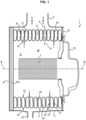
- FIG. 1 represents a heat exchanger 1 comprising only a combustion chamber. In this figure, it is shown in its normal position of use.
- This heat exchanger 1 comprises a casing 2, means for supplying and/or producing hot gases inside said casing and at least one tube 4, inside which circulates the fluid to be heated, in particular water.
- a pump not visible in the figures ensures this circulation of water.
- the casing 2 has a generally tubular shape and extends along a longitudinal axis X-X'. In a known manner, it has at its upper part a sleeve 21 for discharging burnt gases and at its lower part, an outlet orifice connected to a condensate discharge conduit 22.
- the envelope 2 is closed at its rear end by a bottom 23, equipped on its internal face with a disc 230 made of thermally insulating material.
- a facade 24 is fixed to the front of the envelope 2. It includes a central opening, capable of being closed by a door 25.
- the tube 4 is made of a thermally good conductive material, such as metal. It is wound on itself in a helix, so as to form a helical winding 40 and it is arranged inside the casing 2 so that its longitudinal axis X-X' coincides with the longitudinal axis X-X' of the casing 2.
- the means for producing hot gases are preferably a burner 3, for example a gas or fuel oil burner.
- This burner 3 is preferably tubular in shape, and it is arranged inside the casing 2 and inside the winding 40, so that its longitudinal axis X-X' coincides with the longitudinal axis X-X' of the casing 2.
- Burner 3 is fixed on the internal face of door 25.
- the hot gas supply means (not shown in the figures) comprise a burner arranged outside the exchanger and a fan fixed to the door 25 to introduce the hot gases inside the casing 2, into the helical winding 40.
- the space which extends inside the winding 40 thus constitutes a combustion chamber 26.
- the tube 4 has two ends forming an inlet mouth and an outlet mouth, from which the fluid to be heated is respectively introduced and extracted.
- One of these mouths 400 is visible on the Figure 2 .
- the tube 4 has an oblong cross-section, which can be oval or rectangular or rectangular with small sides which can be protruding and curved (as shown in the figures) or protruding and V-shaped.
- the tube 4 thus has an opposite front face 41 and a rear face 42.
- front face designates the face facing the front of the exchanger, i.e. towards the facade 24, while the term “rear face” designates the face facing the rear of the exchanger, i.e. towards the bottom 23.
- the tube 4 has an intrados side 43, oriented towards the axis X-X' and towards the combustion chamber 26 (or towards the burner 3 when the latter is present) and an opposite extrados side 44, oriented towards the casing 2.
- intrados 43 and extrados 44 sides correspond to the short sides of the tube 4.
- the front 41 and rear 42 faces are flat and parallel to each other.
- these front 41 and rear 42 faces could not be strictly flat but substantially flat (for example slightly curved).
- the winding of the tube 4 is carried out in such a way that the major axis Y-Y' of the cross-section of the tube is perpendicular to the longitudinal axis X-X' of the helical winding 40.
- this major axis Y-Y' could also be slightly inclined relative to the longitudinal axis X-X' of the helical winding 40 without departing from the scope of the invention.
- the helical winding 40 has a series of neighboring turns and there is a gap 45 between two neighboring turns, the value of which is calibrated as will be detailed later.
- the front face 41 and the rear face 42 of the tube 4 are located on either side of the gap 45 as seen in the figures 1 And 3 .
- the gases are then evacuated to the outside through the sleeve 21, (see the arrows ii).
- the tube 4 has on its front face 41 and/or its rear face 42, a shoulder 46.
- This shoulder 46 extends from the intrados side 43 towards the extrados side 44 over a part of the height H1 of the straight section of the tube 4.
- this shoulder 46 extends over a height H2 (measured from the intrados 43) less than H1.
- H2 measured from the intrados 43
- H1 the external width L2 of the cross-section of the tube 4 taken at the level of the shoulder 46
- the height H2 measures up to about one-third of the height H1.
- the shoulder 46 may extend over the entire length of the tube 4. Preferably, and as can be seen in the Figure 2 , this shoulder 46 is continuous.
- the first turn of the winding applied against the front 24 does not have this shoulder 46. It could be the same on the last turn of the winding applied against the bottom 23 and the plate 230, in the case where the shoulder 46 is provided on the rear face 42.
- the shoulder 46 makes it possible to create a housing for recovering the soot and slag which are entrained in the hot gases which pass through the interstices 45.
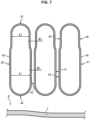
- the gap (or the width) between two neighboring turns, measured at the level of this shoulder 46 is referenced E1 when there is a shoulder 46 only on the front face 41 (see figures 5 And 6 ) or only on the rear face 42 and is referenced E2 when it has a shoulder 46 on the front face 41 and a shoulder 46 on the rear face 42 (see Figure 7 ).
- This gap E1, E2 is therefore wider than the gap (or width) E3 between two neighboring turns, measured where there is no shoulder 46, which makes it possible both to trap the slag in the shoulder 46 and to keep space for the passage of hot gases.
- the winding 40 therefore becomes clogged less quickly, which makes it possible to reduce the frequency of cleaning operations.
- the gaps 45 between two neighboring turns are advantageously calibrated so as to be all identical and thus so that the flows of hot gases circulating there are homogeneous and the heating of the fluid is regular over the entire length of the tube.
- the interstices 45 can be calibrated using one or more combs 5, such as that shown for example in the Figure 4 .
- This comb 5 has a plurality of teeth 50 parallel to each other.
- This comb 5 is arranged relative to the winding 40, so that each of its teeth 50 is introduced into a gap 45, on the extrados side 44 of the tube 4, in order to calibrate this gap 45.
- Each tooth 50 is thus in contact with the front face 41 of a turn of the tube 4 and the rear face 42 of the neighboring turn of the tube 4.
- the teeth 50 do not extend to the level of the shoulder 46.
- the gaps 45 can be calibrated using projecting elements, such as bosses 47 (corrugations) formed on the front face 41 of the tube 4, (as shown in the figures 1 , 2 And 5 ) or on the rear face 42 (not visible in the figures). These bosses are preferably distributed uniformly over the entire length of the tube to obtain gaps 45 of a constant width.
- Each projecting element formed on the front face 41 and/or on the rear face 42 of the tube 4 bears respectively against the rear face 42 and/or the front face 41 of the adjacent turn.
- bosses 47 and the shoulder 46 are made on the same front or rear face of the tube 4, for example on the front face 41 as shown in the Figure 2 , then the bosses 47 are advantageously made on the portion referenced 49 of the face of the tube which does not include the shoulder 46, (see also Figure 5 ).
- the projecting elements such as the bosses 47
- the shoulder 46 are produced on opposite faces of the tube 4 (for example the shoulder 46 on the front face 41 and the projecting elements on the rear face 42 or vice versa), then the projecting elements bear against the portion 49 of the face of the tube which does not include the shoulder 46.
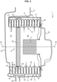
- This exchanger 1' differs from the exchanger 1, in that it comprises a discoidal deflector 6, arranged inside the helical winding 40 of the tube 4, perpendicular to the axis X-X', so as to provide inside the casing 2, on the one hand the combustion chamber 26 which extends between the door 25 and this deflector 6 and where the hot gases are produced or brought, and on the other hand, a condensation chamber 27, which extends between the deflector 6 and the bottom 23 of the casing 2.
- the gas discharge sleeve 21 is connected to the condensation chamber 27.
- the deflector 6 comprises a disc 61 made of thermally insulating material, carried by a thin metal sheet frame 62, provided with a radial peripheral collar 63.
- the deflector 6 is mounted inside the winding 40 of the tube 4, so that its collar 63 is inserted and positioned in a gas-tight manner, in the gap 45 existing between the last turn of the tube 4 located in the combustion chamber 26 and the first turn of the tube 4 located in the condensation chamber 27.
- the shoulder 46 is formed only on the turns of the tube 4 which are located in the combustion chamber 26 and not on the turns of the tube which are located in the condensation chamber 27.
- the hot gases produced by the burner 3 exit the combustion chamber 26 by passing through the gaps 45 formed in the turns of the tube 4 which are located in this combustion chamber 26, (see arrows i) and the slag is trapped in the shoulder 46. Then, the hot gases abut against the casing 2 and are guided towards the extrados side 44 of the turns of the tube 4 located in the condensation chamber 27 (see arrows iii). These hot gases then pass through the gaps 45 formed between the turns, this time from the outside to the inside, towards the condensation chamber 27 (see arrows iv). These hot gases then no longer contain slag, so that the shoulder 46 is not necessary.
- the heat exchanger 1 or 1' comprises a single tube 4 wound in a helix.
- a portion of the turns of the single tube 4 extends into the combustion chamber 26 and the other portion of the turns into the condensation chamber 27.
- the tube 4 can be manufactured by different processes. Two non-limiting examples of manufacturing processes are given below.
- Such a method has the advantage of being able to vary the profile of the section of the tube 4 throughout the helical winding 40 and in particular of forming the shoulder 46. only over a certain part of the length of the tube 4.
- this method makes it possible to create the shoulder 46 only on the turns which are located in the combustion chamber 26, in the case of the condensation heat exchanger 1'.
- this process also makes it possible to have a tube whose faces of the first turn and the last turn are flat, which simplifies the design of the bottom and the front of the exchanger.
Landscapes
- Engineering & Computer Science (AREA)
- Physics & Mathematics (AREA)
- Thermal Sciences (AREA)
- Mechanical Engineering (AREA)
- General Engineering & Computer Science (AREA)
- Chemical & Material Sciences (AREA)
- Combustion & Propulsion (AREA)
- Geometry (AREA)
- Heat-Exchange Devices With Radiators And Conduit Assemblies (AREA)
- Details Of Fluid Heaters (AREA)
Claims (7)
- Wärmetauscher (1, 1'), umfassend:- einen gasdichten Mantel (2), der mit einer Manschette (21) zum Abführen der verbrannten Gase versehen ist,- mindestens ein Rohr (4), das aus einem thermisch gut leitenden Material hergestellt ist und in dessen Innerem ein zu erwärmendes Fluid wie Wasser zirkulieren kann, wobei dieses Rohr (4) schraubenförmig gewickelt ist, um eine schraubenförmige Wicklung (40) mit einer Längsachse (X-X') zu bilden, wobei diese schraubenförmige Wicklung (40) im Inneren des Mantels (2) angeordnet ist,- Mittel zum Zuführen und/oder Erzeugen von heißen Gasen im Inneren des Mantels (2), wie ein Gas-oder Ölbrenner (3), um dort eine Brennkammer (26) zu definieren, wobei diese schraubenförmige Wicklung (40) derart angeordnet ist, dass ein Spalt (45) zwischen zwei benachbarten Windungen entsteht,wobei das mindestens eine Rohr (4) eine Vorderseite (41) und eine Rückseite (42), die sich gegenüberliegen, eine zur Längsachse (X-X') hin ausgerichtete Unterseite (43) und eine gegenüberliegende Oberseite (44) aufweist, die zum Mantel (2) hin ausgerichtet ist, wobei die Vorderseite (41) und die Rückseite (42) des Rohrs (4) eben oder im Wesentlichen eben sind und sich auf beiden Seiten des Spalts (45) befinden, wobei das mindestens eine Rohr (4) auf seiner Vorderseite (41) und/oder seiner Rückseite (42) eine Schulter (46) aufweist, wobei sich diese Schulter (46) ab der Unterseite (43) des Rohrs in Richtung seiner Oberseite (44) über einen Teil der Höhe (H1) des geraden Abschnitts dieses Rohrs (4) erstreckt, wobei dieser Wärmetauscher dadurch gekennzeichnet ist, dass sich diese Schulter (46) ebenfalls entweder über die gesamte Länge des mindestens einen Rohrs (4) erstreckt, das sich in der Brennkammer (26) befindet, oder über die gesamte Länge des mindestens einen Rohrs (4), das sich in der Brennkammer (26) befindet, mit Ausnahme der ersten oder der letzten Windung der schraubenförmigen Wicklung (40),und dass jeder Spalt (45) zwischen zwei benachbarten Windungen entweder mit Hilfe eines Zahns (50) eines Kamms (5), der in den Spalt (45) zwischen zwei Windungen eingeführt wird, auf der Oberseite (44) des Rohrs (4) oder mithilfe mehrerer vorstehender Elemente, wie beispielsweise Erhebungen (47), die auf der Vorderseite (41) und/oder auf der Rückseite (42) des mindestens einen Rohrs (4) ausgebildet sind, kalibriert wird, wobei jedes vorstehende Element, das an einer Windung des Rohrs (4) ausgebildet ist, jeweils an der Rückseite (42) und/oder der Vorderseite (41) der benachbarten Windung anliegt,so dass die Schulter (46) das Auffangen von Ruß und Schlacke ermöglicht, die in den heißen Gasen mitgerissen werden, die durch die Spalte (45) strömen.
- Wärmetauscher (1, 1') nach Anspruch 1, dadurch gekennzeichnet, dass sich die Schulter (46) über eine Höhe (H2), gemessen ab der Unterseite (43), erstreckt, die bis zu etwa einem Drittel der Höhe (H1) des geraden Abschnitts des Rohrs (4) misst.
- Wärmetauscher (1') nach Anspruch 1 oder 2, dadurch gekennzeichnet, dass der Abstand (E1, E2) zwischen zwei benachbarten Windungen, gemessen dort, wo sich die Schulter(n) (46) befindet/befinden, breiter ist als der Abstand (E3) zwischen zwei benachbarten Windungen, gemessen dort, wo es die Schulter (46) nicht gibt.
- Wärmetauscher (1, 1') nach einem der vorhergehenden Ansprüche, dadurch gekennzeichnet, dass ein scheibenförmiger Deflektor (6) im Inneren der schraubenförmigen Wicklung (40) gasdicht angebracht ist, dass dieser scheibenförmige Deflektor (6) im Inneren des Mantels (2) eine Kondensationskammer (27), die sich zwischen dem scheibenförmigen Deflektor (6) und dem Boden des Mantels (2) erstreckt, ausbildet, und eine Brennkammer (26), die sich zwischen dem scheibenförmigen Deflektor (6) und einer Fassade (24) des Mantels (2) erstreckt, an der eine Tür (25) angebracht ist, die die Mittel zum Zuführen und/oder Erzeugen von heißen Gasen trägt und dass die Schulter (46) ausschließlich auf dem Rohr (4) oder den Rohren (4) oder dem Abschnitt des Rohrs (4) ausgebildet ist, das in der Brennkammer (26) positioniert ist.
- Wärmetauscher (1, 1') nach einem der vorhergehenden Ansprüche, dadurch gekennzeichnet, dass der Spalt (45) zwischen den benachbarten Windungen mithilfe mehrerer vorstehender Elemente, wie beispielsweise Erhebungen (47), kalibriert wird, die an der Vorderseite (41) und/oder an der Rückseite (42) des mindestens einen Rohrs (4) ausgebildet sind, wobei jedes vorstehende Element, das an einer Windung des Rohrs (4) ausgebildet ist, jeweils an der Rückseite (42) und/oder an der Vorderseite (41) der benachbarten Windung anliegt, und dass jedes vorstehende Element an dem Teil (49) der Vorderseite und/oder der Rückseite ausgebildet ist, der nicht die Schulter (46) umfasst.
- Wärmetauscher (1, 1') nach einem der Ansprüche 1 bis 4, dadurch gekennzeichnet, dass der Spalt (45) zwischen den benachbarten Windungen mit Hilfe mehrerer vorstehender Elemente, wie beispielsweise Erhebungen (47), kalibriert wird, die an der Vorderseite (41) oder an der Rückseite (42) des mindestens einen Rohrs (4) ausgebildet sind, dass die vorstehenden Elemente und die Schulter (46) auf gegenüberliegenden Seiten des Rohrs (4) ausgebildet sind und dass die vorstehenden Elemente an dem Abschnitt (49) der Seite des Rohrs anliegen, der die Schulter (46) nicht umfasst.
- Wärmetauscher (1, 1') nach einem der vorhergehenden Ansprüche, dadurch gekennzeichnet, dass das Rohr (4) hydrogeformt ist.
Applications Claiming Priority (2)
| Application Number | Priority Date | Filing Date | Title |
|---|---|---|---|
| FR2107688A FR3125326B1 (fr) | 2021-07-16 | 2021-07-16 | Echangeur de chaleur |
| PCT/EP2022/069914 WO2023285680A1 (fr) | 2021-07-16 | 2022-07-15 | Echangeur de chaleur |
Publications (3)
| Publication Number | Publication Date |
|---|---|
| EP4370855A1 EP4370855A1 (de) | 2024-05-22 |
| EP4370855C0 EP4370855C0 (de) | 2025-03-26 |
| EP4370855B1 true EP4370855B1 (de) | 2025-03-26 |
Family
ID=77411919
Family Applications (1)
| Application Number | Title | Priority Date | Filing Date |
|---|---|---|---|
| EP22741788.8A Active EP4370855B1 (de) | 2021-07-16 | 2022-07-15 | Wärmetauscher |
Country Status (8)
| Country | Link |
|---|---|
| US (1) | US12474123B2 (de) |
| EP (1) | EP4370855B1 (de) |
| JP (1) | JP2024525838A (de) |
| KR (1) | KR20240036012A (de) |
| CN (1) | CN117642594A (de) |
| CA (1) | CA3221971A1 (de) |
| FR (1) | FR3125326B1 (de) |
| WO (1) | WO2023285680A1 (de) |
Family Cites Families (13)
| Publication number | Priority date | Publication date | Assignee | Title |
|---|---|---|---|---|
| FR2700608B1 (fr) | 1993-01-15 | 1995-04-07 | Joseph Le Mer | Elément échangeur de chaleur, procédé et dispositif pour le fabriquer. |
| US7096931B2 (en) * | 2001-06-08 | 2006-08-29 | Exxonmobil Research And Engineering Company | Increased heat exchange in two or three phase slurry |
| FR2854229A1 (fr) * | 2003-04-25 | 2004-10-29 | Realisation Mecaniques Engenee | Echangeur de chaleur a condensation |
| JP4852980B2 (ja) * | 2005-11-02 | 2012-01-11 | 株式会社ノーリツ | 温水装置 |
| FR2896856B1 (fr) * | 2006-01-30 | 2008-05-16 | Mer Joseph Le | Echangeur de chaleur a condensation |
| FR2913105B1 (fr) * | 2007-02-28 | 2009-05-08 | Mer Joseph Le | "echangeur de chaleur a condensation comprenant deux faisceaux primaires et un faisceau secondaire" |
| ITMI20071330A1 (it) * | 2007-07-04 | 2009-01-05 | Fondital Spa | Scambiatore di calore per una caldaia a gas e caldaia a gas, in particolare caldaia a condensazione, provvista di tale scambiatore di calore |
| FR2942866B1 (fr) * | 2009-03-06 | 2012-03-23 | Mer Joseph Le | Porte a bruleur integre pour appareil de chauffage |
| FR2955929B1 (fr) * | 2010-02-01 | 2014-04-18 | Mer Joseph Le | Echangeur de chaleur a condensation pour plusieurs fluides et dispositif de production de fluides chauds comprenant un tel echangeur |
| ITTO20130927A1 (it) * | 2013-11-15 | 2015-05-16 | Elbi Int Spa | Scambiatore di calore, in particolare per una caldaia a condensazione |
| JP6223298B2 (ja) * | 2014-07-31 | 2017-11-01 | 株式会社コベルコ マテリアル銅管 | 管内単相流用伝熱管 |
| ITUB20153489A1 (it) * | 2015-09-08 | 2017-03-08 | Riello Spa | Pettine distanziale, scambiatore di calore comprendente tale pettine distanziale e metodo per realizzare tale pettine distanziale |
| CN106322765A (zh) * | 2016-11-09 | 2017-01-11 | 河南省健泰实业有限公司 | 一种用于全预混冷凝式壁挂炉的换热器 |
-
2021
- 2021-07-16 FR FR2107688A patent/FR3125326B1/fr active Active
-
2022
- 2022-07-15 CA CA3221971A patent/CA3221971A1/fr active Pending
- 2022-07-15 CN CN202280049131.1A patent/CN117642594A/zh active Pending
- 2022-07-15 US US18/578,991 patent/US12474123B2/en active Active
- 2022-07-15 WO PCT/EP2022/069914 patent/WO2023285680A1/fr not_active Ceased
- 2022-07-15 EP EP22741788.8A patent/EP4370855B1/de active Active
- 2022-07-15 JP JP2024502214A patent/JP2024525838A/ja active Pending
- 2022-07-15 KR KR1020247002632A patent/KR20240036012A/ko active Pending
Also Published As
| Publication number | Publication date |
|---|---|
| EP4370855C0 (de) | 2025-03-26 |
| FR3125326A1 (fr) | 2023-01-20 |
| EP4370855A1 (de) | 2024-05-22 |
| JP2024525838A (ja) | 2024-07-12 |
| US12474123B2 (en) | 2025-11-18 |
| WO2023285680A1 (fr) | 2023-01-19 |
| CA3221971A1 (fr) | 2023-01-19 |
| KR20240036012A (ko) | 2024-03-19 |
| CN117642594A (zh) | 2024-03-01 |
| FR3125326B1 (fr) | 2023-07-14 |
| US20240337448A1 (en) | 2024-10-10 |
Similar Documents
| Publication | Publication Date | Title |
|---|---|---|
| EP1618341B1 (de) | Brennwertwärmetauscher | |
| EP1965146B1 (de) | Kondensationswärmetauscher, der zwei Primärwärmetauscher und einen Sekundärwärmetauscher umfasst | |
| CA2493393C (fr) | Echangeur de chaleur a condensation a double faisceau de tubes | |
| EP3405723B1 (de) | Kondensationswärmetauscher mit einer wärmetauschervorrichtung | |
| FR3029959A1 (fr) | Refroidissement de composants de moteur | |
| EP0044529B1 (de) | Ablenkgitter für eine Fluidumströmung und seine Anwendung in einer Vorrichtung | |
| EP4370855B1 (de) | Wärmetauscher | |
| LU82393A1 (fr) | Echangeur de chaleur a enceinte en spirale | |
| CA3013114C (fr) | Deflecteur pour echangeur de chaleur a condensation et echangeur muni d'un tel deflecteur | |
| EP0117829A1 (de) | Rohrbündelwärmetauscher | |
| EP1366326B1 (de) | Kondensierender wärmetauscher für einen kessel | |
| FR3079605A1 (fr) | Echangeur thermique a plaques muni d'un bouclier de repartition de debit d'un fluide pour turbomoteur | |
| EP1947386B1 (de) | Heizgaswirbler, insbesondere für Rauchrohrkessel und entsprechender Kessel | |
| EP4370840B1 (de) | Kondensationswärmetauscher | |
| FR3026171A1 (fr) | Dispositif de conditionnement thermique d'un fluide pour vehicule automobile | |
| FR2602857A1 (fr) | Echangeur de chaleur fumee/eau pour une chaudiere a combustible gazeux ou liquide pour production d'eau chaude, et corps de chauffe comportant un tel echangeur de chaleur | |
| WO2004053410A2 (fr) | Tubes de radiateur comportant des perturbateurs et radiateurs associes | |
| WO2000028270A1 (fr) | Echangeur thermique a plaques | |
| BE525890A (de) | ||
| FR2793304A1 (fr) | Bruleur a gaz refroidi a premelange total | |
| BE477253A (de) |
Legal Events
| Date | Code | Title | Description |
|---|---|---|---|
| STAA | Information on the status of an ep patent application or granted ep patent |
Free format text: STATUS: UNKNOWN |
|
| STAA | Information on the status of an ep patent application or granted ep patent |
Free format text: STATUS: THE INTERNATIONAL PUBLICATION HAS BEEN MADE |
|
| PUAI | Public reference made under article 153(3) epc to a published international application that has entered the european phase |
Free format text: ORIGINAL CODE: 0009012 |
|
| STAA | Information on the status of an ep patent application or granted ep patent |
Free format text: STATUS: REQUEST FOR EXAMINATION WAS MADE |
|
| 17P | Request for examination filed |
Effective date: 20240209 |
|
| AK | Designated contracting states |
Kind code of ref document: A1 Designated state(s): AL AT BE BG CH CY CZ DE DK EE ES FI FR GB GR HR HU IE IS IT LI LT LU LV MC MK MT NL NO PL PT RO RS SE SI SK SM TR |
|
| DAV | Request for validation of the european patent (deleted) | ||
| DAX | Request for extension of the european patent (deleted) | ||
| GRAP | Despatch of communication of intention to grant a patent |
Free format text: ORIGINAL CODE: EPIDOSNIGR1 |
|
| STAA | Information on the status of an ep patent application or granted ep patent |
Free format text: STATUS: GRANT OF PATENT IS INTENDED |
|
| INTG | Intention to grant announced |
Effective date: 20241025 |
|
| GRAS | Grant fee paid |
Free format text: ORIGINAL CODE: EPIDOSNIGR3 |
|
| GRAA | (expected) grant |
Free format text: ORIGINAL CODE: 0009210 |
|
| STAA | Information on the status of an ep patent application or granted ep patent |
Free format text: STATUS: THE PATENT HAS BEEN GRANTED |
|
| AK | Designated contracting states |
Kind code of ref document: B1 Designated state(s): AL AT BE BG CH CY CZ DE DK EE ES FI FR GB GR HR HU IE IS IT LI LT LU LV MC MK MT NL NO PL PT RO RS SE SI SK SM TR |
|
| REG | Reference to a national code |
Ref country code: GB Ref legal event code: FG4D Free format text: NOT ENGLISH |
|
| REG | Reference to a national code |
Ref country code: CH Ref legal event code: EP |
|
| REG | Reference to a national code |
Ref country code: DE Ref legal event code: R096 Ref document number: 602022012328 Country of ref document: DE |
|
| REG | Reference to a national code |
Ref country code: IE Ref legal event code: FG4D Free format text: LANGUAGE OF EP DOCUMENT: FRENCH |
|
| U01 | Request for unitary effect filed |
Effective date: 20250416 |
|
| U07 | Unitary effect registered |
Designated state(s): AT BE BG DE DK EE FI FR IT LT LU LV MT NL PT RO SE SI Effective date: 20250424 |
|
| PG25 | Lapsed in a contracting state [announced via postgrant information from national office to epo] |
Ref country code: RS Free format text: LAPSE BECAUSE OF FAILURE TO SUBMIT A TRANSLATION OF THE DESCRIPTION OR TO PAY THE FEE WITHIN THE PRESCRIBED TIME-LIMIT Effective date: 20250626 |
|
| PG25 | Lapsed in a contracting state [announced via postgrant information from national office to epo] |
Ref country code: NO Free format text: LAPSE BECAUSE OF FAILURE TO SUBMIT A TRANSLATION OF THE DESCRIPTION OR TO PAY THE FEE WITHIN THE PRESCRIBED TIME-LIMIT Effective date: 20250626 |
|
| PG25 | Lapsed in a contracting state [announced via postgrant information from national office to epo] |
Ref country code: HR Free format text: LAPSE BECAUSE OF FAILURE TO SUBMIT A TRANSLATION OF THE DESCRIPTION OR TO PAY THE FEE WITHIN THE PRESCRIBED TIME-LIMIT Effective date: 20250326 |
|
| PG25 | Lapsed in a contracting state [announced via postgrant information from national office to epo] |
Ref country code: GR Free format text: LAPSE BECAUSE OF FAILURE TO SUBMIT A TRANSLATION OF THE DESCRIPTION OR TO PAY THE FEE WITHIN THE PRESCRIBED TIME-LIMIT Effective date: 20250627 |
|
| U20 | Renewal fee for the european patent with unitary effect paid |
Year of fee payment: 4 Effective date: 20250616 |
|
| PG25 | Lapsed in a contracting state [announced via postgrant information from national office to epo] |
Ref country code: SM Free format text: LAPSE BECAUSE OF FAILURE TO SUBMIT A TRANSLATION OF THE DESCRIPTION OR TO PAY THE FEE WITHIN THE PRESCRIBED TIME-LIMIT Effective date: 20250326 |
|
| PG25 | Lapsed in a contracting state [announced via postgrant information from national office to epo] |
Ref country code: ES Free format text: LAPSE BECAUSE OF FAILURE TO SUBMIT A TRANSLATION OF THE DESCRIPTION OR TO PAY THE FEE WITHIN THE PRESCRIBED TIME-LIMIT Effective date: 20250326 |
|
| PG25 | Lapsed in a contracting state [announced via postgrant information from national office to epo] |
Ref country code: PL Free format text: LAPSE BECAUSE OF FAILURE TO SUBMIT A TRANSLATION OF THE DESCRIPTION OR TO PAY THE FEE WITHIN THE PRESCRIBED TIME-LIMIT Effective date: 20250326 |
|
| PGFP | Annual fee paid to national office [announced via postgrant information from national office to epo] |
Ref country code: TR Payment date: 20250709 Year of fee payment: 4 |
|
| PG25 | Lapsed in a contracting state [announced via postgrant information from national office to epo] |
Ref country code: SK Free format text: LAPSE BECAUSE OF FAILURE TO SUBMIT A TRANSLATION OF THE DESCRIPTION OR TO PAY THE FEE WITHIN THE PRESCRIBED TIME-LIMIT Effective date: 20250326 |
|
| PG25 | Lapsed in a contracting state [announced via postgrant information from national office to epo] |
Ref country code: IS Free format text: LAPSE BECAUSE OF FAILURE TO SUBMIT A TRANSLATION OF THE DESCRIPTION OR TO PAY THE FEE WITHIN THE PRESCRIBED TIME-LIMIT Effective date: 20250726 |
|
| PG25 | Lapsed in a contracting state [announced via postgrant information from national office to epo] |
Ref country code: CZ Free format text: LAPSE BECAUSE OF FAILURE TO SUBMIT A TRANSLATION OF THE DESCRIPTION OR TO PAY THE FEE WITHIN THE PRESCRIBED TIME-LIMIT Effective date: 20250326 |
|
| PLBE | No opposition filed within time limit |
Free format text: ORIGINAL CODE: 0009261 |
|
| STAA | Information on the status of an ep patent application or granted ep patent |
Free format text: STATUS: NO OPPOSITION FILED WITHIN TIME LIMIT |
|
| REG | Reference to a national code |
Ref country code: CH Ref legal event code: L10 Free format text: ST27 STATUS EVENT CODE: U-0-0-L10-L00 (AS PROVIDED BY THE NATIONAL OFFICE) Effective date: 20260211 |
|
| REG | Reference to a national code |
Ref country code: CH Ref legal event code: H13 Free format text: ST27 STATUS EVENT CODE: U-0-0-H10-H13 (AS PROVIDED BY THE NATIONAL OFFICE) Effective date: 20260224 |
|
| 26N | No opposition filed |
Effective date: 20260105 |