EP4371684A1 - Procédé de tournage - Google Patents
Procédé de tournage Download PDFInfo
- Publication number
- EP4371684A1 EP4371684A1 EP22208257.0A EP22208257A EP4371684A1 EP 4371684 A1 EP4371684 A1 EP 4371684A1 EP 22208257 A EP22208257 A EP 22208257A EP 4371684 A1 EP4371684 A1 EP 4371684A1
- Authority
- EP
- European Patent Office
- Prior art keywords
- attack
- correction data
- angles
- cutting edge
- different angles
- Prior art date
- Legal status (The legal status is an assumption and is not a legal conclusion. Google has not performed a legal analysis and makes no representation as to the accuracy of the status listed.)
- Pending
Links
Images


Classifications
-
- G—PHYSICS
- G05—CONTROLLING; REGULATING
- G05B—CONTROL OR REGULATING SYSTEMS IN GENERAL; FUNCTIONAL ELEMENTS OF SUCH SYSTEMS; MONITORING OR TESTING ARRANGEMENTS FOR SUCH SYSTEMS OR ELEMENTS
- G05B19/00—Program-control systems
- G05B19/02—Program-control systems electric
- G05B19/18—Numerical control [NC], i.e. automatically operating machines, in particular machine tools, e.g. in a manufacturing environment, so as to execute positioning, movement or co-ordinated operations by means of program data in numerical form
- G05B19/402—Numerical control [NC], i.e. automatically operating machines, in particular machine tools, e.g. in a manufacturing environment, so as to execute positioning, movement or co-ordinated operations by means of program data in numerical form characterised by control arrangements for positioning, e.g. centring a tool relative to a hole in the workpiece, additional detection means to correct position
-
- B—PERFORMING OPERATIONS; TRANSPORTING
- B23—MACHINE TOOLS; METAL-WORKING NOT OTHERWISE PROVIDED FOR
- B23B—TURNING; BORING
- B23B1/00—Methods for turning or working essentially requiring the use of turning-machines; Use of auxiliary equipment in connection with such methods
-
- B—PERFORMING OPERATIONS; TRANSPORTING
- B23—MACHINE TOOLS; METAL-WORKING NOT OTHERWISE PROVIDED FOR
- B23B—TURNING; BORING
- B23B27/00—Tools for turning or boring machines; Tools of a similar kind in general; Accessories therefor
- B23B27/14—Cutting tools of which the bits or tips or cutting inserts are of special material
- B23B27/141—Specially shaped plate-like cutting inserts, i.e. length greater or equal to width, width greater than or equal to thickness
- B23B27/145—Specially shaped plate-like cutting inserts, i.e. length greater or equal to width, width greater than or equal to thickness characterised by having a special shape
-
- B—PERFORMING OPERATIONS; TRANSPORTING
- B23—MACHINE TOOLS; METAL-WORKING NOT OTHERWISE PROVIDED FOR
- B23B—TURNING; BORING
- B23B27/00—Tools for turning or boring machines; Tools of a similar kind in general; Accessories therefor
- B23B27/14—Cutting tools of which the bits or tips or cutting inserts are of special material
- B23B27/16—Cutting tools of which the bits or tips or cutting inserts are of special material with exchangeable cutting bits or cutting inserts, e.g. able to be clamped
- B23B27/1603—Cutting tools of which the bits or tips or cutting inserts are of special material with exchangeable cutting bits or cutting inserts, e.g. able to be clamped with specially shaped plate-like exchangeable cutting inserts, e.g. chip-breaking groove
- B23B27/1611—Cutting tools of which the bits or tips or cutting inserts are of special material with exchangeable cutting bits or cutting inserts, e.g. able to be clamped with specially shaped plate-like exchangeable cutting inserts, e.g. chip-breaking groove characterised by having a special shape
-
- B—PERFORMING OPERATIONS; TRANSPORTING
- B23—MACHINE TOOLS; METAL-WORKING NOT OTHERWISE PROVIDED FOR
- B23B—TURNING; BORING
- B23B29/00—Holders for non-rotary cutting tools; Boring bars or boring heads; Accessories for tool holders
- B23B29/04—Tool holders for a single cutting tool
-
- B—PERFORMING OPERATIONS; TRANSPORTING
- B23—MACHINE TOOLS; METAL-WORKING NOT OTHERWISE PROVIDED FOR
- B23B—TURNING; BORING
- B23B2200/00—Details of cutting inserts
- B23B2200/04—Overall shape
- B23B2200/0423—Irregular
-
- B—PERFORMING OPERATIONS; TRANSPORTING
- B23—MACHINE TOOLS; METAL-WORKING NOT OTHERWISE PROVIDED FOR
- B23B—TURNING; BORING
- B23B2200/00—Details of cutting inserts
- B23B2200/04—Overall shape
- B23B2200/049—Triangular
-
- B—PERFORMING OPERATIONS; TRANSPORTING
- B23—MACHINE TOOLS; METAL-WORKING NOT OTHERWISE PROVIDED FOR
- B23B—TURNING; BORING
- B23B2200/00—Details of cutting inserts
- B23B2200/16—Supporting or bottom surfaces
- B23B2200/161—Supporting or bottom surfaces with projections
-
- B—PERFORMING OPERATIONS; TRANSPORTING
- B23—MACHINE TOOLS; METAL-WORKING NOT OTHERWISE PROVIDED FOR
- B23Q—DETAILS, COMPONENTS, OR ACCESSORIES FOR MACHINE TOOLS, e.g. ARRANGEMENTS FOR COPYING OR CONTROLLING; MACHINE TOOLS IN GENERAL CHARACTERISED BY THE CONSTRUCTION OF PARTICULAR DETAILS OR COMPONENTS; COMBINATIONS OR ASSOCIATIONS OF METAL-WORKING MACHINES, NOT DIRECTED TO A PARTICULAR RESULT
- B23Q17/00—Arrangements for observing, indicating or measuring on machine tools
- B23Q17/22—Arrangements for observing, indicating or measuring on machine tools for indicating or measuring existing or desired position of tool or work
- B23Q17/2233—Arrangements for observing, indicating or measuring on machine tools for indicating or measuring existing or desired position of tool or work for adjusting the tool relative to the workpiece
-
- G—PHYSICS
- G05—CONTROLLING; REGULATING
- G05B—CONTROL OR REGULATING SYSTEMS IN GENERAL; FUNCTIONAL ELEMENTS OF SUCH SYSTEMS; MONITORING OR TESTING ARRANGEMENTS FOR SUCH SYSTEMS OR ELEMENTS
- G05B19/00—Program-control systems
- G05B19/02—Program-control systems electric
- G05B19/18—Numerical control [NC], i.e. automatically operating machines, in particular machine tools, e.g. in a manufacturing environment, so as to execute positioning, movement or co-ordinated operations by means of program data in numerical form
- G05B19/404—Numerical control [NC], i.e. automatically operating machines, in particular machine tools, e.g. in a manufacturing environment, so as to execute positioning, movement or co-ordinated operations by means of program data in numerical form characterised by control arrangements for compensation, e.g. for backlash, overshoot, tool offset, tool wear, temperature, machine construction errors, load, inertia
-
- G—PHYSICS
- G05—CONTROLLING; REGULATING
- G05B—CONTROL OR REGULATING SYSTEMS IN GENERAL; FUNCTIONAL ELEMENTS OF SUCH SYSTEMS; MONITORING OR TESTING ARRANGEMENTS FOR SUCH SYSTEMS OR ELEMENTS
- G05B2219/00—Program-control systems
- G05B2219/30—Nc systems
- G05B2219/41—Servomotor, servo controller till figures
- G05B2219/41209—Lookup table with compensation as function of reference and feedback value
-
- G—PHYSICS
- G05—CONTROLLING; REGULATING
- G05B—CONTROL OR REGULATING SYSTEMS IN GENERAL; FUNCTIONAL ELEMENTS OF SUCH SYSTEMS; MONITORING OR TESTING ARRANGEMENTS FOR SUCH SYSTEMS OR ELEMENTS
- G05B2219/00—Program-control systems
- G05B2219/30—Nc systems
- G05B2219/50—Machine tool, machine tool null till machine tool work handling
- G05B2219/50353—Tool, probe inclination, orientation to surface, posture, attitude
Definitions
- a method for turning in a processing machine and a computer program for controlling turning in a processing machine are provided.
- tools are typically used in which a usable cutting edge section, which has a rounded cutting corner area and straight first and second cutting edge areas adjacent to this on both sides, is aligned at a predetermined, unchangeable angle of attack that the first straight cutting edge area encloses with a rotation axis of the workpiece to be machined.
- a usable cutting edge section which has a rounded cutting corner area and straight first and second cutting edge areas adjacent to this on both sides, is aligned at a predetermined, unchangeable angle of attack that the first straight cutting edge area encloses with a rotation axis of the workpiece to be machined.
- the main dimensions are usually the distances of the cutting corner area in three mutually orthogonal directions (X, Y, Z) from a reference point, which are entered in a tool table.
- a tool zero point which is located in the axis center of a tool holder, or an axial stop point for the tool, serves as a reference point.
- further functional dimensions such as a corner radius of the cutting corner area, so that the calculations of turning cycles and machining processes work without errors.
- the main dimensions entered in the tool table usually represent previously determined dimensions of the tool.
- CNC processing machines and their control programs therefore usually provide the option of entering the difference between the actual dimensions and the entered dimensions of the tool as correction values in order to compensate for these tolerances.
- the deviations are typically measured in at least two mutually orthogonal directions by measuring tangents to the cutting edge area.
- the correction values are typically in the order of less than 1 mm, so this is a fine correction.
- the individual measurement of the correction data for a number of different angles of attack can be carried out directly, for example, by measuring the tool at the various angles of attack and determining deviations of the actual positions of the tool from the target positions of the tool at the various angles of attack. This can be done manually or using appropriate measuring probes.
- the measurement of the correction data can also be carried out indirectly, for example by measuring the machined workpiece. The measurement should be carried out at previously defined points so that the connection between the determined deviation and the angle of attack can be clearly established.
- the angles of attack for which the correction data are measured should cover at least a relatively large range for the angle of attack from the angle range that is also used in turning, in order to enable a particularly reliable correction.
- the number of angles of attack for which correction data are individually measured should also not be too small in order to enable a reliable correction of tolerance-related position deviations even for a large range of different angles of attack.
- the correction data can in particular contain a position deviation of the cutting edge section in a radial direction with respect to the axis of rotation of the workpiece, preferably at least for angles of attack greater than or equal to 90°, position deviations in at least two mutually orthogonal directions for each of the different angles of attack, particularly preferably for at least three mutually orthogonal directions.
- the correction data can also contain, for example, a correction value for a deviation of the curvature of the rounded cutting corner area from a target radius, etc.
- the usable cutting edge section can have a rounded cutting corner region and straight first and second cutting edge regions adjacent to this cutting corner region on both sides.
- the correction data are measured for at least three different angles of attack. In this case, a reasonable range of angles of attack can be reliably covered. Measuring the correction data for more than three angles of attack, preferably for at least five different angles of attack, leads to even better results.
- the correction data are measured for different angles of attack that cover an angle of attack range of at least 90°.
- a correction can be made particularly reliably for angles of attack that cover the entire range of possible angles of attack.
- an angle of attack range of at least 120°, more preferably of at least 150° is covered.
- the measurement of the correction data can be carried out, for example, for a large number of angles of attack that are essentially evenly distributed over the angle of attack range.
- the correction data comprise at least correction data for two mutually orthogonal directions, which determine the deviation from target positions in these directions, preferably at least correction data for three mutually orthogonal directions, at least for each of the plurality of different angles of attack that is greater than or equal to 90°.
- a particularly reliable correction can be made for different angles of attack.
- further correction values can also be determined, in particular, for example, a correction value for a deviation of the cutting corner area from a target corner radius.
- the correction data for two mutually orthogonal directions represent position deviations of tangents in mutually orthogonal directions to the rounded cutting corner area of the cutting edge section compared to target positions.
- This correction data can be used in particular for longitudinal turning with a feed parallel to the longitudinal axis of the workpiece. and for turning operations with a radial feed relative to the longitudinal axis of the workpiece, a particularly reliable correction can be made.
- Such position deviations are typically of a magnitude of ⁇ 1 mm.
- the correction data for each of the plurality of different angles of attack have at least one correction value for a corner radius, which represents a deviation from a target corner radius.
- the correction value can be, for example, the difference between the target corner radius and an actual corner radius that corresponds to the actual corner radius or at least comes closer to it.
- a particularly simple correction depending on the angle of attack can also be provided for turning steps in which the feed has both an axial direction component along the rotation axis of the workpiece and a radial direction component with respect to the rotation axis of the workpiece, i.e. when machining inclined or longitudinally curved surfaces.
- the known algorithms and methods for corner radius correction can then be used, in particular with the corresponding correction data depending on the angle of attack for each of the angles of attack used in the machining.
- correction data for further angles of attack are calculated, in particular for angles of attack that lie between the angles of attack for which correction data were measured.
- correction data can be provided for the entire range of possible angles of attack, which enable a reliable compensation of tolerance-related position deviations without correction data having to be measured for all possible angles of attack.
- the correction data for the further angles of attack can preferably be calculated by interpolation, extrapolation and/or by means of a stored correction function.
- the cutting insert has a plurality of cutting edge sections that can be used for turning and correction data are stored for several Cutting edge sections are measured.
- the correction data for each of the cutting edge sections can be determined in essentially the same way.
- the correction data is measured by measuring the installed tool with the cutting insert arranged on it.
- the tool with the cutting insert arranged on it can be measured outside the processing machine, e.g. on a tool presetting device. It is alternatively possible to measure the tool when it is mounted in the processing machine, e.g. using a corresponding measuring probe provided there.
- the correction data is measured by measuring a component manufactured with the tool. Both dimensional deviations and shape deviations of the component can be taken into account. By measuring the component manufactured with the tool in conjunction with knowledge of the angle of attack used in production, the correction data for a number of different angles of attack can be reliably determined. This is particularly reliable if a test component is used for which a specified machining is carried out at specified angles of attack. By measuring the component manufactured with the tool, tolerance-related position deviations that are not only caused by the tool itself, such as axis errors of the processing machine, elastic deflections between the processing machine, tool and workpiece, etc., can also be compensated for the various angles of attack.
- the cutting insert is arranged on the front side transversely to a longitudinal axis of the tool holder such that a surface normal of a chip surface of the cutting insert has a main directional component parallel to the longitudinal axis of the tool holder.
- the angle of attack can be changed in a particularly simple manner by rotating it around the longitudinal axis of the tool holder or an axis parallel to it.
- the computer program contains instructions for controlling a turning operation in a processing machine with a tool that has a tool holder held in a machine-side holder with an exchangeable cutting insert attached to it, which has at least one cutting edge section that can be used for turning a workpiece rotating about a rotation axis, with at least one rounded cutting corner region and at least one straight first cutting edge region adjacent to this cutting corner region, such that an angle of attack that the first cutting edge region encloses with the rotation axis is varied by rotating the tool holder about its longitudinal axis or an axis parallel to it.
- the computer program is designed in such a way that correction data for compensating for tolerance-related position deviations of the cutting edge section can be entered for a plurality of different angles of attack in order to enable automated correction of the control of the tool during turning depending on the angle of attack.
- the computer program thus provides correction data to compensate for tolerance-related position deviations as a function of the angle of attack. Since the correction data to compensate for tolerance-related position deviations of the cutting edge section can be entered for a number of different angles of attack, a reliable correction of tolerance-related position deviations can also be carried out in turning operations in which a change in the angle of attack is possible without changing the tool, so that particularly dimensionally accurate workpieces can be achieved. It is possible, for example, to enter correction data for a large number of different angles of attack, in order to then use this later when machining at this angle of attack.
- angles of attack for which the correction data can be entered should cover at least a relatively large range for the angle of attack from the angle range that is also used in turning, in order to enable particularly reliable correction.
- the number of angles of attack for which correction data can be entered individually should also not be too small in order to enable reliable correction of tolerance-related position deviations even for a large range of different angles of attack.
- the correction data that can be entered can contain position deviations of the cutting edge section in at least two mutually orthogonal directions for each of the different angles of attack, particularly preferably for at least three mutually orthogonal directions, at least for angles of attack greater than or equal to 90°.
- the correction data that can be entered can also contain, for example, a correction value for a deviation of the curvature of the rounded cutting corner area from a target radius, etc.
- the computer program can, for example, be designed so that it is executed directly in the machine control of the processing machine. However, it is also possible, for example, to design the computer program so that it is executed on an external computer that is or will be connected to the machine control.
- the correction data can be entered for at least three different angles of attack. In this case, a reasonable range of angles of attack can be reliably covered. If the correction data can be entered for at least five different angles of attack, even better results can be achieved.
- the correction data can be entered for different angles of attack that cover an angle of attack range of at least 90°.
- an angle of attack range for which correction data can be entered is at least 120°, more preferably at least 150°.
- the correction data that can be entered have at least correction data for two mutually orthogonal directions, which determine the deviation from target positions in these directions, at least for each of the plurality of different angles of attack that is greater than or equal to 90°.
- the correction data that can be entered preferably have at least correction data for three mutually orthogonal directions for each of the plurality of different angles of attack.
- further correction values can also be determined, in particular, for example, a correction value for a deviation of the cutting corner area from a target corner radius.
- the correction data for each of the plurality of different angles of attack have at least one correction value for a corner radius, which represents a deviation from a target corner radius.
- a particularly simple correction depending on the angle of attack can also be provided for turning machining steps in which the feed has both an axial direction component along the rotation axis of the workpiece and a radial direction component with respect to the rotation axis of the workpiece, i.e. when machining inclined or longitudinally curved surfaces.
- the known algorithms and methods for corner radius correction can then be used, in particular with the corresponding correction data depending on the angle of attack for each of the angles of attack used in the machining.
- the computer program calculates, based on entered correction data for the plurality of different angles of attack, correction data for further angles of attack, in particular for angles of attack that lie between the angles of attack for which Correction data have been entered.
- correction data can be provided as a function of the angle of attack for the entire range of possible angles of attack, which enables reliable compensation of tolerance-related position deviations without the need to measure correction data for all possible angles of attack.
- the correction data for the other angles of attack can preferably be calculated by interpolation, extrapolation and/or using a stored correction function.
- the Fig. 1 to Fig. 5 The schematically illustrated method for turning takes place in a processing machine, which can be, for example, a CNC-controlled turning-milling center with a plurality of controllable axes.
- a processing machine which can be, for example, a CNC-controlled turning-milling center with a plurality of controllable axes.
- Such processing machines are known and, to simplify the description, no details of the processing machine are shown.
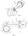
- the tool 100 used in the method has a tool holder 1 which carries a replaceable cutting insert 2 which is attached thereto in a rotationally fixed manner.
- the tool holder 1 extends along a longitudinal axis L and has a first end 11 which is designed to be held in a machine-side receptacle (not shown) of the processing machine.
- a seat for the replaceable cutting insert 2 is formed at a second end 12 of the tool holder 1 opposite the first end 11 in such a way that the cutting insert 2 attached to the seat extends transversely to the longitudinal axis L and an upper side 21 of the cutting insert 2 which serves as a chip surface is oriented away from the second end 12 of the tool holder 1.
- the upper side 21 can be provided, for example, with a chip breaker structure for shaping, diverting and breaking chips produced during turning, which is not shown in the figures for the sake of simplicity.
- the replaceable cutting insert 2 is fastened to the front of the second end 12 of the tool holder 1 by means of a fastening screw 3 that passes through a through hole in the cutting insert 2.
- the rotationally fixed fastening of the cutting insert 2 to the tool holder 1 can be realized, for example, by a positive interaction of an underside of the cutting insert 2 with the second end 12 of the tool holder 1.
- the cutting insert 2 is made of a hard and wear-resistant material and can in particular be made of cemented carbide, cermet or a cutting ceramic.
- the tool holder 1 is made of a tougher material, such as tool steel.
- the tool holder 1 is designed in the region of its second end 12 as a tool shank which, in a section perpendicular to the longitudinal axis L, has a cross-sectional shape which essentially corresponds to a basic shape of the cutting insert 2 attached thereto.
- the cutting insert 2 has at least one cutting edge section 22 that can be used for turning a workpiece W rotating about a rotation axis Z, which has at least one rounded cutting corner region 22a and at least one straight first cutting edge region 22b adjacent to this cutting corner region 22a.
- the first cutting edge region 22b particularly preferably adjoins one end of the rounded cutting corner region 22a essentially tangentially.
- the usable cutting edge section 22 also has a straight second cutting edge region 22c that adjoins the other end of the rounded cutting corner region 22a. The latter also preferably adjoins the other end of the cutting corner region 22a essentially tangentially.
- the usable cutting edge section 22 extends transversely to the longitudinal axis L of the tool holder 1. Particularly preferably, the usable cutting edge section 22 can extend in a plane that is perpendicular to the longitudinal axis L of the tool holder 1. The usable cutting edge portion 22 protrudes laterally from the second end 12 of the tool holder 1 with respect to the longitudinal axis L.
- the cutting insert 2 has a plurality of usable cutting edge sections 22, 22', 22", each having at least one rounded cutting corner region 22a and at least one straight first cutting edge region 22b adjacent thereto, as shown in Fig.4 is shown schematically.
- these usable cutting edge sections 22, 22', 22" each merge directly into one another, so that the upper side 21 of the cutting insert 2 is surrounded by a circumferential cutting edge that protrudes laterally on all sides beyond the second end 12 of the tool holder 1.
- the transition from the upper side 21 to the circumferential side surface of the cutting insert 2 is designed as a cutting edge only in some areas.
- the usable cutting edge sections 22, 22', 22" all extend in a common plane transverse to the longitudinal axis L of the tool holder 1, with this plane particularly preferably extending perpendicular to the longitudinal axis L of the tool holder 1.
- the cutting insert 2 in the example shown has a total of three rounded cutting corner regions 22a, it is also possible, for example, for the cutting insert 2 to have fewer than three or more than three rounded cutting corner regions 22a. Different rounded cutting corner regions 22a can differ from one another, for example, in particular by the size of the included corner angle which the adjacent first and second straight cutting edge regions 22b, 22c enclose with one another.
- an approach angle ⁇ , ⁇ 1, ⁇ 2, which the straight first cutting edge area 22b encloses with the rotation axis Z of the workpiece W, can be varied. This can either take place while the cutting insert 2 is in engagement with the workpiece, or in an interim period when the cutting insert 2 is not in engagement with the workpiece.
- a feed direction B is in the Fig. 4 and Fig. 5 shown schematically.
- the change in the angle of attack ⁇ , ⁇ 1, ⁇ 2 is achieved by rotating the tool holder 1 by a certain angle about its longitudinal axis L or, alternatively, by rotating it about an axis parallel to the longitudinal axis L of the tool holder 1.
- the usable cutting edge section 22, 22', 22" can also be changed if several usable cutting edge sections are present.
- the rotation of the tool holder 1 about the longitudinal axis L or an axis parallel thereto can take place in particular by a corresponding rotation of the machine-side holder of the processing machine, which must be equipped with this functionality for this purpose, which can e.g. already be provided in the processing machine itself or can e.g. be implemented by a corresponding adapter.
- Synchronized with the rotation of the tool holder 1 about its longitudinal axis L at least one movement in a radial direction with respect to the axis of rotation R of the workpiece W preferably takes place in order to avoid an unwanted change in the cutting depth.
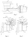
- Fig. 6a to Fig. 6d schematically show different values of the angle of attack ⁇ for a cutting insert 2 with a basic shape slightly different from the cutting insert 2 shown previously, whereby the same reference symbols are used to designate corresponding areas.
- Fig. 6a an alignment of the cutting insert 2 is shown in which a small angle of attack ⁇ is realized, which is significantly smaller than 45°, whereas in Fig. 6b the angle of attack ⁇ is approximately 45°.
- Fig. 6c represents a situation where the angle of attack ⁇ is slightly larger than 90°, and Fig. 6d an even significantly larger angle of attack of approximately 120°. It is immediately apparent that the largest possible angle of attack that can be achieved depends, among other things, on the specific corner angle of the cutting corner area 22a used.
- the angle of attack ⁇ that can be achieved also depends, among other things, on the feed direction during turning, i.e. whether the feed with which the tool 100 is moved relative to the workpiece W has only an axial direction component or also a radial direction component with respect to the rotation axis Z of the workpiece W or even only a radial direction component, and the respective contour of the workpiece to be produced.
- the workpiece contact point P i.e. the point of the cutting edge section 22, which ultimately determines the dimension of the machined surface of the workpiece W, changes its position on the cutting edge section 22 depending on the selected angle of attack ⁇ .
- Fig.7 is now an example for a turning operation with the Fig. 6d
- the significance of tolerance-related position deviations of the cutting edge section 22 is explained by the angle of attack ⁇ shown, whereby this is Fig.7 shown schematically and greatly enlarged.
- the actual position of the cutting edge section 22 during turning may not correspond to the target position.
- a position x actual of the cutting corner area 22a in a radial direction x with respect to the rotation axis Z may not correspond to the target position x target in this direction, but deviates from it by a correction value ⁇ x, as in Fig.7 is shown schematically. This has an effect on the dimension of the workpiece W produced in particular when a turning operation is carried out with a directional component of the feed parallel to the longitudinal axis Z of the workpiece W.
- the correction value ⁇ x can be determined in particular by measuring the distance of a tangent parallel to the rotation axis Z to the cutting corner area 22 from the target position x target , as in Fig.7 is shown schematically. Furthermore, a position z actual of the cutting corner region 22a in an axial direction z orthogonal thereto with respect to the rotation axis Z may not correspond to the target position z target in this direction, but deviates from it by a correction value ⁇ z, as also shown in Fig.7 is shown schematically.
- the correction value ⁇ z can be determined in particular by measuring the distance of a tangent perpendicular to the rotation axis Z in the radial direction to the cutting corner area 22 from the target position z target , as in Fig.7 is shown schematically.
- the actual position y actual of the cutting corner region 22a can also deviate from the target position y target by a correction value ⁇ y, which corresponds to a deviation of the "tip height" during turning.
- ⁇ y which corresponds to a deviation of the "tip height" during turning.
- the dimensional accuracy of the workpiece is also influenced by whether the rounded cutting corner area 22a runs exactly along a predetermined target corner radius r soll or deviates from it, for example by having a different actual corner radius r ist .
- a predetermined target corner radius r soll or deviates from it for example by having a different actual corner radius r ist .
- the actual corner radius r actual can be measured and a difference between this and the target corner radius r target can be used as a correction value ⁇ r for the corner radius.
- the rounded cutting corner area 22a can also deviate from a partially circular course, e.g.
- the deviation of the rounded cutting corner region 22a from a target corner radius r target has an effect on the resulting dimensions of the workpiece, particularly in the case of turning with a feed that has both an axial direction component and a radial direction component with respect to the rotation axis Z of the workpiece W, since in this case the radius correction functions typically stored on the machine side, which are based on a predetermined target corner radius r target, do not lead to satisfactory results.
- the turning operation must be adapted accordingly so that it corrects these tolerance-related position deviations.
- correction data is measured for a plurality of different angles of attack ⁇ . For example, for several different angles of attack ⁇ that are less than 90°, correction data ⁇ x, ⁇ r and optionally ⁇ y are measured, and for several different angles of attack ⁇ that are greater than or equal to 90°, correction data ⁇ x, ⁇ z and optionally ⁇ y and/or ⁇ r are measured. This is shown by way of example in the following table. It is understood that the specific values of the correction data contained in the table are only examples.
- the correction value ⁇ y for all angles of attack ⁇ is 0.000. This corresponds to a situation in which the tip height of the tool 100 is optimally set and therefore no further correction is required in this spatial direction. However, it is also possible that a correction is also necessary in this direction. In the example, however, correction values for ⁇ x and ⁇ r are determined for all measured angles of attack and also correction values ⁇ z for all measured angles of attack ⁇ ⁇ 90°. Although in this example correction data is measured for a total of seven values of the angle of attack ⁇ , it is also possible for fewer than seven values of the angle of attack ⁇ or for more than seven values of the angle of attack ⁇ .
- correction data for at least three different angles of attack ⁇ , more preferably for at least five different angles of attack ⁇ .
- correction data is measured for an angle of attack range that covers 180°, it is also possible, for example, to measure correction data only for a smaller angle of attack range.
- correction data is measured for an angle of attack range of at least 90°, preferably of at least 120°.
- correction data ⁇ r for the corner radius is determined for the entire angle of attack range for which measurements are taken. Alternatively, it is also possible to measure correction data for the corner radius only for a part of the angles of attack.
- correction data is measured at equal angular intervals of 30° over the angle of attack range. Alternatively, measurements at other angular intervals or even at unequal angular intervals are also possible. If turning is to be carried out at an angle of attack ⁇ for which no measured correction data ⁇ x, ⁇ y, ⁇ z, ⁇ r are available, such as an angle of attack of 25° in the specific example, the correction data ⁇ x, ⁇ y, ⁇ z, ⁇ r for this angle of attack are calculated from the available measured correction data ⁇ x, ⁇ y, ⁇ z, ⁇ r. This can be done in the simplest way, for example, by interpolating between the correction data that were measured for the closest angles of attack.
- the calculation can also be done, for example, as an extrapolation starting from one side.
- These procedures each have the advantage that even for angles of attack for which no correction data ⁇ x, ⁇ y, ⁇ z, ⁇ r have been measured previously, the corresponding correction data can be provided, which can then be used to calculate a
- the tool 100 can also be controlled for these angles of attack in such a way that tolerance-related position deviations are reliably corrected.
- the correction data ⁇ x, ⁇ y, ⁇ z, ⁇ r shown as examples in Table 1 for different angles of attack ⁇ can be determined, for example, by measuring the tool 100 before it is used, so that position deviations caused by tolerances of the tool 100 can be reliably compensated for during turning at different angles of attack ⁇ . In this way, good compensation of tolerance-related position deviations is possible, since machine-side tolerances are often already corrected in another way in the machine itself.
- the tool 100 can be measured, for example, optically or using a measuring probe.
- a computer program which contains instructions such that a compensation of tolerance-related position deviations is reliably possible even if a change in the angle of attack ⁇ occurs during turning.
- the computer program has an input mask for this purpose, which can be filled manually, for example, with the appropriate input means, such as in particular the usual input means keyboard, mouse, touchscreen, etc., for a plurality of different angles of attack ⁇ with the correction data ⁇ x, ⁇ y, ⁇ z, ⁇ r to compensate for tolerance-related position deviations of the cutting edge section 22.
- the appropriate input means such as in particular the usual input means keyboard, mouse, touchscreen, etc.
- An embodiment in which the input of the correction data ⁇ x, ⁇ y, ⁇ z, ⁇ r can be carried out at least by an operator, but is preferred because in this case additional compensations can be made in a simple manner even in unusual constellations.
- the computer program contains instructions so that, based on the entered correction data ⁇ x, ⁇ y, ⁇ z, ⁇ r, an automated correction of the control of the tool 1 during turning is implemented for a plurality of angles of attack ⁇ depending on the angle of attack ⁇ .
- an automated correction is carried out as a function of the angle of attack and this also applies to other angles of attack ⁇ for which no correction data were entered. This is achieved - as already described above with reference to the method - by calculating the corresponding correction data for other angles of attack ⁇ , which can be done, for example, by interpolation between entered correction data, extrapolation based on entered correction data or by other stored mathematical functions.
- the correction data ⁇ x, ⁇ y, ⁇ z, ⁇ r applicable to the respective angle of attack ⁇ are then used to control the processing machine in such a way that the tolerance-related position deviations of the cutting edge section 22 are corrected during turning by the processing machine correcting the position accordingly in the corresponding spatial directions in which position deviations exist.
Landscapes
- Engineering & Computer Science (AREA)
- Mechanical Engineering (AREA)
- Human Computer Interaction (AREA)
- Manufacturing & Machinery (AREA)
- Physics & Mathematics (AREA)
- General Physics & Mathematics (AREA)
- Automation & Control Theory (AREA)
- Numerical Control (AREA)
Priority Applications (2)
| Application Number | Priority Date | Filing Date | Title |
|---|---|---|---|
| EP22208257.0A EP4371684A1 (fr) | 2022-11-18 | 2022-11-18 | Procédé de tournage |
| PCT/EP2023/079223 WO2024104709A1 (fr) | 2022-11-18 | 2023-10-20 | Procédé de tournage |
Applications Claiming Priority (1)
| Application Number | Priority Date | Filing Date | Title |
|---|---|---|---|
| EP22208257.0A EP4371684A1 (fr) | 2022-11-18 | 2022-11-18 | Procédé de tournage |
Publications (1)
| Publication Number | Publication Date |
|---|---|
| EP4371684A1 true EP4371684A1 (fr) | 2024-05-22 |
Family
ID=88511621
Family Applications (1)
| Application Number | Title | Priority Date | Filing Date |
|---|---|---|---|
| EP22208257.0A Pending EP4371684A1 (fr) | 2022-11-18 | 2022-11-18 | Procédé de tournage |
Country Status (2)
| Country | Link |
|---|---|
| EP (1) | EP4371684A1 (fr) |
| WO (1) | WO2024104709A1 (fr) |
Citations (5)
| Publication number | Priority date | Publication date | Assignee | Title |
|---|---|---|---|---|
| WO2004022270A1 (fr) * | 2002-09-03 | 2004-03-18 | Kennametal Inc. | Porte-outil |
| EP3001264A1 (fr) * | 2014-07-16 | 2016-03-30 | Yamazaki Mazak Corporation | Dispositif de commande de transformation par tournage et programme d'assistance de transformation par tournage |
| WO2019120824A1 (fr) | 2017-12-22 | 2019-06-27 | Ceratizit Austria Gesellschaft M.B.H. | Système d'outil et procédé d'usinage par tournage |
| DE102020129898A1 (de) * | 2019-11-15 | 2021-05-20 | Fanuc Corporation | Bearbeitungsverfahren und Objekt |
| EP4059642A1 (fr) * | 2021-03-17 | 2022-09-21 | AB Sandvik Coromant | Procédé pour une tour cnc |
-
2022
- 2022-11-18 EP EP22208257.0A patent/EP4371684A1/fr active Pending
-
2023
- 2023-10-20 WO PCT/EP2023/079223 patent/WO2024104709A1/fr not_active Ceased
Patent Citations (5)
| Publication number | Priority date | Publication date | Assignee | Title |
|---|---|---|---|---|
| WO2004022270A1 (fr) * | 2002-09-03 | 2004-03-18 | Kennametal Inc. | Porte-outil |
| EP3001264A1 (fr) * | 2014-07-16 | 2016-03-30 | Yamazaki Mazak Corporation | Dispositif de commande de transformation par tournage et programme d'assistance de transformation par tournage |
| WO2019120824A1 (fr) | 2017-12-22 | 2019-06-27 | Ceratizit Austria Gesellschaft M.B.H. | Système d'outil et procédé d'usinage par tournage |
| DE102020129898A1 (de) * | 2019-11-15 | 2021-05-20 | Fanuc Corporation | Bearbeitungsverfahren und Objekt |
| EP4059642A1 (fr) * | 2021-03-17 | 2022-09-21 | AB Sandvik Coromant | Procédé pour une tour cnc |
Also Published As
| Publication number | Publication date |
|---|---|
| WO2024104709A1 (fr) | 2024-05-23 |
Similar Documents
| Publication | Publication Date | Title |
|---|---|---|
| EP2175799B1 (fr) | Ébauche avec codage, et procédé de fabrication de pièce de dentisterie formée | |
| EP2358494B1 (fr) | Procédé de traitement des flancs de dentelures essentiellement cylindriques, mais modifiées et bombées en largeur dans le procédé de roulement en diagonale | |
| DE102021109711B4 (de) | Waferstellungsspezifisches Abtastverfahren und -system | |
| EP2923790B1 (fr) | Procédé de meulage de roues coniques dans un procédé de rectification en bout | |
| DE102005039010B4 (de) | Bearbeitungsvorrichtung mit Vermessungseinrichtung für ein Modell | |
| DE3702594A1 (de) | Verfahren zum schleifen von mindestens zwei nocken einer nockenwelle | |
| WO2022101197A1 (fr) | Corps de mesure pour la vérification d'écarts géométriques d'une machine-outil à 3 axes, machine-outil à trois axes et procédé de compensation d'écarts géométriques d'une machine-outil à 3 axes | |
| DE69022820T2 (de) | Verfahren zum numerisch gesteuerten Schraubenschneiden für genaue Oberflächenendbearbeitung der Schraube. | |
| EP1947538A1 (fr) | Procédé de commande d'un outil mobile, dispositif d'introduction tout comme machine de traitement | |
| EP3118699A2 (fr) | Procede de fabrication d'une piece dentee comprenant une geometrie de surface modifiee | |
| DE19710458B4 (de) | Verfahren zum funkenerosiven Bearbeiten | |
| EP2274128B1 (fr) | Outil de coupe pour l'usinage par enlèvement de copeaux de pièces d'oeuvre ainsi qu'élément de retenue pour une plaquette de coupe | |
| DE69117447T2 (de) | Drahtschneidefunkerosionsverfahren zur Eingangsbearbeitung und Vorrichtung zur Durchführung des Verfahrens | |
| DE3829363C1 (fr) | ||
| DE102012201732B4 (de) | Numerisch gesteuerte Werkzeugmaschine und Verfahren zum Steuern eines automatischen rotatorischen Ausrichtvorgangs eines Zahnrads an der Werkzeugmaschine | |
| EP3139230A2 (fr) | Procede de fabrication d'une piece dentee comprenant une geometrie de surface modifiee | |
| EP0962843B1 (fr) | Procédé d'affichage non-linéaire de trajectoires d'outil d'une machine outil | |
| EP4371684A1 (fr) | Procédé de tournage | |
| DE19907363A1 (de) | Topologisches Profilieren von Schleifschnecken für das kontinuierliche Wälzschleifen von Verzahnungen | |
| EP1577055B1 (fr) | Dispositif de meulage et procédé de génération d'une surface d'enlèvement de rateau contourée avec un angle d'enlèvement variable | |
| DE102021132246A1 (de) | Zahnradbearbeitungsverfahren und Zahnradbearbeitungsvorrichtung | |
| DE102021123259A1 (de) | Schneidplatte zum hochgeschwindigkeitsstirnfräsen | |
| EP4367561B1 (fr) | Procédé de compensation de la déviation d'un outil lors de l'usinage d'une pièce, et machine-outil associée | |
| DE69504733T2 (de) | Verfahren zur Bestimmung des Wiederherstellungsfehlers einer Kantenschneidmaschine mit zugehöriger Konturlesevorrichtung und Anwendung der Selbstkalibrierung an der zugehörigen Vorrichtung | |
| EP1341065A2 (fr) | Procédé d'usinage de cavités rectilignes dans les surfaces de pièces |
Legal Events
| Date | Code | Title | Description |
|---|---|---|---|
| PUAI | Public reference made under article 153(3) epc to a published international application that has entered the european phase |
Free format text: ORIGINAL CODE: 0009012 |
|
| STAA | Information on the status of an ep patent application or granted ep patent |
Free format text: STATUS: THE APPLICATION HAS BEEN PUBLISHED |
|
| AK | Designated contracting states |
Kind code of ref document: A1 Designated state(s): AL AT BE BG CH CY CZ DE DK EE ES FI FR GB GR HR HU IE IS IT LI LT LU LV MC ME MK MT NL NO PL PT RO RS SE SI SK SM TR |
|
| STAA | Information on the status of an ep patent application or granted ep patent |
Free format text: STATUS: REQUEST FOR EXAMINATION WAS MADE |
|
| 17P | Request for examination filed |
Effective date: 20241121 |
|
| RBV | Designated contracting states (corrected) |
Designated state(s): AL AT BE BG CH CY CZ DE DK EE ES FI FR GB GR HR HU IE IS IT LI LT LU LV MC ME MK MT NL NO PL PT RO RS SE SI SK SM TR |
|
| STAA | Information on the status of an ep patent application or granted ep patent |
Free format text: STATUS: EXAMINATION IS IN PROGRESS |
|
| 17Q | First examination report despatched |
Effective date: 20251106 |