EP4371785A1 - Pneumatique radial pour avion - Google Patents
Pneumatique radial pour avion Download PDFInfo
- Publication number
- EP4371785A1 EP4371785A1 EP23209939.0A EP23209939A EP4371785A1 EP 4371785 A1 EP4371785 A1 EP 4371785A1 EP 23209939 A EP23209939 A EP 23209939A EP 4371785 A1 EP4371785 A1 EP 4371785A1
- Authority
- EP
- European Patent Office
- Prior art keywords
- belt
- belt layer
- pneumatic tire
- layers
- axially
- Prior art date
- Legal status (The legal status is an assumption and is not a legal conclusion. Google has not performed a legal analysis and makes no representation as to the accuracy of the status listed.)
- Granted
Links
Images


Classifications
-
- B—PERFORMING OPERATIONS; TRANSPORTING
- B60—VEHICLES IN GENERAL
- B60C—VEHICLE TYRES; TYRE INFLATION; TYRE CHANGING; CONNECTING VALVES TO INFLATABLE ELASTIC BODIES IN GENERAL; DEVICES OR ARRANGEMENTS RELATED TO TYRES
- B60C11/00—Tyre tread bands; Tread patterns; Anti-skid inserts
- B60C11/03—Tread patterns
- B60C11/13—Tread patterns characterised by the groove cross-section, e.g. for buttressing or preventing stone-trapping
- B60C11/1376—Three dimensional block surfaces departing from the enveloping tread contour
-
- B—PERFORMING OPERATIONS; TRANSPORTING
- B60—VEHICLES IN GENERAL
- B60C—VEHICLE TYRES; TYRE INFLATION; TYRE CHANGING; CONNECTING VALVES TO INFLATABLE ELASTIC BODIES IN GENERAL; DEVICES OR ARRANGEMENTS RELATED TO TYRES
- B60C11/00—Tyre tread bands; Tread patterns; Anti-skid inserts
- B60C11/03—Tread patterns
- B60C11/0327—Tread patterns characterised by special properties of the tread pattern
- B60C11/0332—Tread patterns characterised by special properties of the tread pattern by the footprint-ground contacting area of the tyre tread
-
- B—PERFORMING OPERATIONS; TRANSPORTING
- B64—AIRCRAFT; AVIATION; COSMONAUTICS
- B64C—AEROPLANES; HELICOPTERS
- B64C25/00—Alighting gear
- B64C25/32—Alighting gear characterised by elements which contact the ground or similar surface
- B64C25/34—Alighting gear characterised by elements which contact the ground or similar surface wheeled type, e.g. multi-wheeled bogies
- B64C25/36—Arrangements or adaptations of wheels, tyres or axles in general
-
- B—PERFORMING OPERATIONS; TRANSPORTING
- B60—VEHICLES IN GENERAL
- B60C—VEHICLE TYRES; TYRE INFLATION; TYRE CHANGING; CONNECTING VALVES TO INFLATABLE ELASTIC BODIES IN GENERAL; DEVICES OR ARRANGEMENTS RELATED TO TYRES
- B60C11/00—Tyre tread bands; Tread patterns; Anti-skid inserts
- B60C11/0083—Tyre tread bands; Tread patterns; Anti-skid inserts characterised by the curvature of the tyre tread
-
- B—PERFORMING OPERATIONS; TRANSPORTING
- B60—VEHICLES IN GENERAL
- B60C—VEHICLE TYRES; TYRE INFLATION; TYRE CHANGING; CONNECTING VALVES TO INFLATABLE ELASTIC BODIES IN GENERAL; DEVICES OR ARRANGEMENTS RELATED TO TYRES
- B60C11/00—Tyre tread bands; Tread patterns; Anti-skid inserts
- B60C11/01—Shape of the shoulders between tread and sidewall, e.g. rounded, stepped or cantilevered
-
- B—PERFORMING OPERATIONS; TRANSPORTING
- B60—VEHICLES IN GENERAL
- B60C—VEHICLE TYRES; TYRE INFLATION; TYRE CHANGING; CONNECTING VALVES TO INFLATABLE ELASTIC BODIES IN GENERAL; DEVICES OR ARRANGEMENTS RELATED TO TYRES
- B60C11/00—Tyre tread bands; Tread patterns; Anti-skid inserts
- B60C11/03—Tread patterns
- B60C11/0306—Patterns comprising block rows or discontinuous ribs
-
- B—PERFORMING OPERATIONS; TRANSPORTING
- B60—VEHICLES IN GENERAL
- B60C—VEHICLE TYRES; TYRE INFLATION; TYRE CHANGING; CONNECTING VALVES TO INFLATABLE ELASTIC BODIES IN GENERAL; DEVICES OR ARRANGEMENTS RELATED TO TYRES
- B60C11/00—Tyre tread bands; Tread patterns; Anti-skid inserts
- B60C11/03—Tread patterns
- B60C11/04—Tread patterns in which the raised area of the pattern consists only of continuous circumferential ribs, e.g. zig-zag
-
- B—PERFORMING OPERATIONS; TRANSPORTING
- B60—VEHICLES IN GENERAL
- B60C—VEHICLE TYRES; TYRE INFLATION; TYRE CHANGING; CONNECTING VALVES TO INFLATABLE ELASTIC BODIES IN GENERAL; DEVICES OR ARRANGEMENTS RELATED TO TYRES
- B60C15/00—Tyre beads, e.g. ply turn-up or overlap
- B60C15/0009—Tyre beads, e.g. ply turn-up or overlap features of the carcass terminal portion
-
- B—PERFORMING OPERATIONS; TRANSPORTING
- B60—VEHICLES IN GENERAL
- B60C—VEHICLE TYRES; TYRE INFLATION; TYRE CHANGING; CONNECTING VALVES TO INFLATABLE ELASTIC BODIES IN GENERAL; DEVICES OR ARRANGEMENTS RELATED TO TYRES
- B60C15/00—Tyre beads, e.g. ply turn-up or overlap
- B60C15/04—Bead cores
-
- B—PERFORMING OPERATIONS; TRANSPORTING
- B60—VEHICLES IN GENERAL
- B60C—VEHICLE TYRES; TYRE INFLATION; TYRE CHANGING; CONNECTING VALVES TO INFLATABLE ELASTIC BODIES IN GENERAL; DEVICES OR ARRANGEMENTS RELATED TO TYRES
- B60C9/00—Reinforcements or ply arrangement of pneumatic tyres
- B60C9/005—Reinforcements made of different materials, e.g. hybrid or composite cords
-
- B—PERFORMING OPERATIONS; TRANSPORTING
- B60—VEHICLES IN GENERAL
- B60C—VEHICLE TYRES; TYRE INFLATION; TYRE CHANGING; CONNECTING VALVES TO INFLATABLE ELASTIC BODIES IN GENERAL; DEVICES OR ARRANGEMENTS RELATED TO TYRES
- B60C9/00—Reinforcements or ply arrangement of pneumatic tyres
- B60C9/02—Carcasses
- B60C9/04—Carcasses the reinforcing cords of each carcass ply arranged in a substantially parallel relationship
-
- B—PERFORMING OPERATIONS; TRANSPORTING
- B60—VEHICLES IN GENERAL
- B60C—VEHICLE TYRES; TYRE INFLATION; TYRE CHANGING; CONNECTING VALVES TO INFLATABLE ELASTIC BODIES IN GENERAL; DEVICES OR ARRANGEMENTS RELATED TO TYRES
- B60C9/00—Reinforcements or ply arrangement of pneumatic tyres
- B60C9/18—Structure or arrangement of belts or breakers, crown-reinforcing or cushioning layers
-
- B—PERFORMING OPERATIONS; TRANSPORTING
- B60—VEHICLES IN GENERAL
- B60C—VEHICLE TYRES; TYRE INFLATION; TYRE CHANGING; CONNECTING VALVES TO INFLATABLE ELASTIC BODIES IN GENERAL; DEVICES OR ARRANGEMENTS RELATED TO TYRES
- B60C9/00—Reinforcements or ply arrangement of pneumatic tyres
- B60C9/18—Structure or arrangement of belts or breakers, crown-reinforcing or cushioning layers
- B60C9/20—Structure or arrangement of belts or breakers, crown-reinforcing or cushioning layers built-up from rubberised plies each having all cords arranged substantially parallel
-
- B—PERFORMING OPERATIONS; TRANSPORTING
- B60—VEHICLES IN GENERAL
- B60C—VEHICLE TYRES; TYRE INFLATION; TYRE CHANGING; CONNECTING VALVES TO INFLATABLE ELASTIC BODIES IN GENERAL; DEVICES OR ARRANGEMENTS RELATED TO TYRES
- B60C9/00—Reinforcements or ply arrangement of pneumatic tyres
- B60C9/18—Structure or arrangement of belts or breakers, crown-reinforcing or cushioning layers
- B60C9/20—Structure or arrangement of belts or breakers, crown-reinforcing or cushioning layers built-up from rubberised plies each having all cords arranged substantially parallel
- B60C9/2003—Structure or arrangement of belts or breakers, crown-reinforcing or cushioning layers built-up from rubberised plies each having all cords arranged substantially parallel characterised by the materials of the belt cords
-
- B—PERFORMING OPERATIONS; TRANSPORTING
- B60—VEHICLES IN GENERAL
- B60C—VEHICLE TYRES; TYRE INFLATION; TYRE CHANGING; CONNECTING VALVES TO INFLATABLE ELASTIC BODIES IN GENERAL; DEVICES OR ARRANGEMENTS RELATED TO TYRES
- B60C9/00—Reinforcements or ply arrangement of pneumatic tyres
- B60C9/18—Structure or arrangement of belts or breakers, crown-reinforcing or cushioning layers
- B60C9/20—Structure or arrangement of belts or breakers, crown-reinforcing or cushioning layers built-up from rubberised plies each having all cords arranged substantially parallel
- B60C9/22—Structure or arrangement of belts or breakers, crown-reinforcing or cushioning layers built-up from rubberised plies each having all cords arranged substantially parallel the plies being arranged with all cords disposed along the circumference of the tyre
-
- B—PERFORMING OPERATIONS; TRANSPORTING
- B60—VEHICLES IN GENERAL
- B60C—VEHICLE TYRES; TYRE INFLATION; TYRE CHANGING; CONNECTING VALVES TO INFLATABLE ELASTIC BODIES IN GENERAL; DEVICES OR ARRANGEMENTS RELATED TO TYRES
- B60C9/00—Reinforcements or ply arrangement of pneumatic tyres
- B60C9/18—Structure or arrangement of belts or breakers, crown-reinforcing or cushioning layers
- B60C9/20—Structure or arrangement of belts or breakers, crown-reinforcing or cushioning layers built-up from rubberised plies each having all cords arranged substantially parallel
- B60C9/22—Structure or arrangement of belts or breakers, crown-reinforcing or cushioning layers built-up from rubberised plies each having all cords arranged substantially parallel the plies being arranged with all cords disposed along the circumference of the tyre
- B60C9/2204—Structure or arrangement of belts or breakers, crown-reinforcing or cushioning layers built-up from rubberised plies each having all cords arranged substantially parallel the plies being arranged with all cords disposed along the circumference of the tyre obtained by circumferentially narrow strip winding
-
- B—PERFORMING OPERATIONS; TRANSPORTING
- B60—VEHICLES IN GENERAL
- B60C—VEHICLE TYRES; TYRE INFLATION; TYRE CHANGING; CONNECTING VALVES TO INFLATABLE ELASTIC BODIES IN GENERAL; DEVICES OR ARRANGEMENTS RELATED TO TYRES
- B60C9/00—Reinforcements or ply arrangement of pneumatic tyres
- B60C9/18—Structure or arrangement of belts or breakers, crown-reinforcing or cushioning layers
- B60C9/26—Folded plies
- B60C9/263—Folded plies further characterised by an endless zigzag configuration in at least one belt ply, i.e. no cut edge being present
-
- B—PERFORMING OPERATIONS; TRANSPORTING
- B60—VEHICLES IN GENERAL
- B60C—VEHICLE TYRES; TYRE INFLATION; TYRE CHANGING; CONNECTING VALVES TO INFLATABLE ELASTIC BODIES IN GENERAL; DEVICES OR ARRANGEMENTS RELATED TO TYRES
- B60C9/00—Reinforcements or ply arrangement of pneumatic tyres
- B60C9/02—Carcasses
- B60C9/04—Carcasses the reinforcing cords of each carcass ply arranged in a substantially parallel relationship
- B60C2009/0475—Particular materials of the carcass cords
-
- B—PERFORMING OPERATIONS; TRANSPORTING
- B60—VEHICLES IN GENERAL
- B60C—VEHICLE TYRES; TYRE INFLATION; TYRE CHANGING; CONNECTING VALVES TO INFLATABLE ELASTIC BODIES IN GENERAL; DEVICES OR ARRANGEMENTS RELATED TO TYRES
- B60C9/00—Reinforcements or ply arrangement of pneumatic tyres
- B60C9/18—Structure or arrangement of belts or breakers, crown-reinforcing or cushioning layers
- B60C9/20—Structure or arrangement of belts or breakers, crown-reinforcing or cushioning layers built-up from rubberised plies each having all cords arranged substantially parallel
- B60C2009/2012—Structure or arrangement of belts or breakers, crown-reinforcing or cushioning layers built-up from rubberised plies each having all cords arranged substantially parallel with particular configuration of the belt cords in the respective belt layers
-
- B—PERFORMING OPERATIONS; TRANSPORTING
- B60—VEHICLES IN GENERAL
- B60C—VEHICLE TYRES; TYRE INFLATION; TYRE CHANGING; CONNECTING VALVES TO INFLATABLE ELASTIC BODIES IN GENERAL; DEVICES OR ARRANGEMENTS RELATED TO TYRES
- B60C9/00—Reinforcements or ply arrangement of pneumatic tyres
- B60C9/18—Structure or arrangement of belts or breakers, crown-reinforcing or cushioning layers
- B60C9/20—Structure or arrangement of belts or breakers, crown-reinforcing or cushioning layers built-up from rubberised plies each having all cords arranged substantially parallel
- B60C2009/2048—Structure or arrangement of belts or breakers, crown-reinforcing or cushioning layers built-up from rubberised plies each having all cords arranged substantially parallel characterised by special physical properties of the belt plies
-
- B—PERFORMING OPERATIONS; TRANSPORTING
- B60—VEHICLES IN GENERAL
- B60C—VEHICLE TYRES; TYRE INFLATION; TYRE CHANGING; CONNECTING VALVES TO INFLATABLE ELASTIC BODIES IN GENERAL; DEVICES OR ARRANGEMENTS RELATED TO TYRES
- B60C9/00—Reinforcements or ply arrangement of pneumatic tyres
- B60C9/18—Structure or arrangement of belts or breakers, crown-reinforcing or cushioning layers
- B60C9/20—Structure or arrangement of belts or breakers, crown-reinforcing or cushioning layers built-up from rubberised plies each having all cords arranged substantially parallel
- B60C9/22—Structure or arrangement of belts or breakers, crown-reinforcing or cushioning layers built-up from rubberised plies each having all cords arranged substantially parallel the plies being arranged with all cords disposed along the circumference of the tyre
- B60C2009/2214—Structure or arrangement of belts or breakers, crown-reinforcing or cushioning layers built-up from rubberised plies each having all cords arranged substantially parallel the plies being arranged with all cords disposed along the circumference of the tyre characterised by the materials of the zero degree ply cords
-
- B—PERFORMING OPERATIONS; TRANSPORTING
- B60—VEHICLES IN GENERAL
- B60C—VEHICLE TYRES; TYRE INFLATION; TYRE CHANGING; CONNECTING VALVES TO INFLATABLE ELASTIC BODIES IN GENERAL; DEVICES OR ARRANGEMENTS RELATED TO TYRES
- B60C11/00—Tyre tread bands; Tread patterns; Anti-skid inserts
- B60C11/01—Shape of the shoulders between tread and sidewall, e.g. rounded, stepped or cantilevered
- B60C2011/013—Shape of the shoulders between tread and sidewall, e.g. rounded, stepped or cantilevered provided with a recessed portion
-
- B—PERFORMING OPERATIONS; TRANSPORTING
- B60—VEHICLES IN GENERAL
- B60C—VEHICLE TYRES; TYRE INFLATION; TYRE CHANGING; CONNECTING VALVES TO INFLATABLE ELASTIC BODIES IN GENERAL; DEVICES OR ARRANGEMENTS RELATED TO TYRES
- B60C11/00—Tyre tread bands; Tread patterns; Anti-skid inserts
- B60C11/03—Tread patterns
- B60C2011/0337—Tread patterns characterised by particular design features of the pattern
- B60C2011/0339—Grooves
-
- B—PERFORMING OPERATIONS; TRANSPORTING
- B60—VEHICLES IN GENERAL
- B60C—VEHICLE TYRES; TYRE INFLATION; TYRE CHANGING; CONNECTING VALVES TO INFLATABLE ELASTIC BODIES IN GENERAL; DEVICES OR ARRANGEMENTS RELATED TO TYRES
- B60C11/00—Tyre tread bands; Tread patterns; Anti-skid inserts
- B60C11/03—Tread patterns
- B60C2011/0337—Tread patterns characterised by particular design features of the pattern
- B60C2011/0386—Continuous ribs
-
- B—PERFORMING OPERATIONS; TRANSPORTING
- B60—VEHICLES IN GENERAL
- B60C—VEHICLE TYRES; TYRE INFLATION; TYRE CHANGING; CONNECTING VALVES TO INFLATABLE ELASTIC BODIES IN GENERAL; DEVICES OR ARRANGEMENTS RELATED TO TYRES
- B60C15/00—Tyre beads, e.g. ply turn-up or overlap
- B60C15/04—Bead cores
- B60C2015/042—Bead cores characterised by the material of the core, e.g. alloy
-
- B—PERFORMING OPERATIONS; TRANSPORTING
- B60—VEHICLES IN GENERAL
- B60C—VEHICLE TYRES; TYRE INFLATION; TYRE CHANGING; CONNECTING VALVES TO INFLATABLE ELASTIC BODIES IN GENERAL; DEVICES OR ARRANGEMENTS RELATED TO TYRES
- B60C15/00—Tyre beads, e.g. ply turn-up or overlap
- B60C15/04—Bead cores
- B60C2015/046—Cable cores, i.e. cores made-up of twisted wires
-
- B—PERFORMING OPERATIONS; TRANSPORTING
- B60—VEHICLES IN GENERAL
- B60C—VEHICLE TYRES; TYRE INFLATION; TYRE CHANGING; CONNECTING VALVES TO INFLATABLE ELASTIC BODIES IN GENERAL; DEVICES OR ARRANGEMENTS RELATED TO TYRES
- B60C2200/00—Tyres specially adapted for particular applications
- B60C2200/02—Tyres specially adapted for particular applications for aircrafts
Definitions
- the present disclosure relates generally to pneumatic tires and preferably to radial aircraft tires.
- Aircraft tires are subject to extreme operating conditions including a heavy load per tire coupled with high speeds. Further, prolonged taxiing can build up high heat. The foregoing and other factors cause tread wear.
- the tire is typically re-treaded, which saves costs relative to just disposing of worn tires. Retreading may occur several times for a single tire. However, as the tread wears beyond an acceptable level, the tire is required to be removed from service and be re-treaded, which still has associated costs and down time. Therefore, extending the useful life of the tread, for example, by reducing uneven tread wear, is very desirable.
- the invention relates to a tire in accordance with claim 1 or 14 respectively.
- a pneumatic tire in accordance with a first preferred aspect of the invention comprises: a carcass; a belt reinforcing structure comprising a plurality of belt layers that include at least one spiral belt layer and at least one zigzag belt layer, each of the at least one spiral belt layers having cords arranged at an angle of 5° or less with respect to an equatorial plane of the pneumatic tire and each of the at least one zigzag belt layers having cords arranged at an angle of 5° to 40° with respect to the equatorial plane and extending in alternation to turnaround points at each lateral edge of the belt reinforcing structure, wherein a first belt layer of the plurality of belt layers located radially outward of the carcass is one of the at least one spiral belt layer, and wherein the first belt has a belt width less than a widest belt layer of the plurality of belt layers; and a tread comprising two or more main grooves extending circumferentially continuously around the pneumatic tire and defining a plurality of ribs
- a pneumatic tire in accordance with another aspect of the invention comprises: a carcass; a belt reinforcing structure comprising a plurality of belt layers that include at least one spiral belt layer and at least one zigzag belt layer, each of the at least one spiral belt layers having cords arranged at an angle of 5° or less with respect to an equatorial plane of the pneumatic tire and each of the at least one zigzag belt layers having cords arranged at an angle of 5° to 40° with respect to the equatorial plane and extending in alternation to turnaround points at each lateral edge of the belt reinforcing structure, wherein a first belt layer of the plurality of belt layers located radially outward of the carcass is one of the at least one spiral belt layer, and wherein the first belt has a belt width less than a widest belt layer of the plurality of belt layers; and a tread comprising two or more main grooves extending circumferentially continuously around the pneumatic tire and defining a plurality of ribs that include two
- Axial and “axially” mean lines or directions that are parallel to the axis of rotation of the tire.
- Bead or “bead core” generally means that part of the tire comprising an annular tensile member of radially inner beads that are associated with holding the tire to the rim.
- Carcass means the tire structure apart from the belt structure, tread, under tread over the plies, but including the beads.
- “Circumferential” means lines or directions extending along the perimeter of the surface of the annular tread perpendicular to the axial direction.
- Equatorial plane means the plane perpendicular to the axis of rotation of the tire and passing through the center of the tire tread.
- “Groove” means an elongated void area in a tread that may extend in a circumferential, lateral or angled manner about the tread in a straight, curved, or zigzag configuration. Circumferentially and laterally extending grooves sometimes have common portions.
- the "groove width" is equal to tread surface area occupied by a groove or groove portion, the width of which is in question, divided by the length of such groove or groove portion; thus, the groove width is its average width over its length.
- Grooves may be of varying depths in a tire. The depth of a groove may vary around the circumference of the tread, or the depth of one groove may be constant but vary from the depth of another groove in the tire. If such narrow or wide grooves have a substantially reduced depth, as compared to wide circumferential grooves which is the interconnect, they are regarded as forming "stiffener elements” tending to maintain a rib-like character in tread region involved.
- Inner means toward the inside of the tire.
- “Lateral” and “laterally” are used to indicate axial directions across the tread of the tire.
- “Lateral edges” mean a line tangent to the axially outermost tread contact patch or footprint as measured under normal load and tire inflation, the lines being parallel to the equatorial centerplane.
- “Monofilament” means a cord having only one filament.
- Plastic means a layer of rubber-coated parallel cords.
- Ring and radially are used to mean directions radially toward or away from the axis of rotation of the tire.
- Ring means a circumferentially extending strip of rubber on the tread which is defined by at least one circumferential groove and either a second such groove or a lateral edge, the strip being laterally undivided by full-depth grooves.
- Shader means the upper portion of sidewall just below the tread edge.
- Thread means a molded rubber component which includes that portion of the tire that comes into contact with the road when the tire is normally inflated and under normal load.
- the tread has a depth conventionally measured from the tread outer surface to the bottom of the deepest groove of the tire.
- Turnup ply and “turnup portion” refers to a portion of a carcass ply that wraps around one bead only.
- Zigzag belt reinforcing structure means a belt structure formed of at least two layers of cords interwoven together wherein preferably a ribbon of parallel cords having 1 to 20 cords in each ribbon are laid up in an alternating pattern extending at an angle typically between 2° and 45° or 5° and 40° between lateral edges of the belt, and more preferably between 3° and 11°, and most preferably between 5° and 11° degrees.
- the present disclosure relates preferably to aircraft radial tires with tread configurations that may reduce uneven tread wear and, consequently, may increase the useful life of the tires.
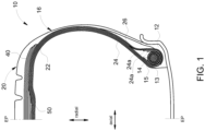
- FIG. 1 illustrates a cross-sectional view of one half of an aircraft radial tire 10 (also referred to herein as an aircraft tire or a pneumatic tire or a tire) according to at least one embodiment of the present disclosure.
- the pneumatic tire 10 is symmetrical about the equatorial plane EP so that only one half is illustrated.
- the pneumatic tire 10 may comprises a pair of bead portions 12 each containing a bead 14 embedded therein.
- An example of a bead suitable for use in a pneumatic tire 10 of the present disclosure is shown in U.S. Pat. No. 6,571,847 .
- the bead 14 is preferably formed by a plurality of sheath wires 15 (e.g., steel sheath wires) surrounding a central core 13 that is a lightweight metal alloy material having a specific weight less than steel metal (e.g., aluminum, aluminum alloy, or other lightweight alloy such as magnesium, titanium, or any metal alloy having a weight less than steel).
- a lightweight metal alloy material having a specific weight less than steel metal (e.g., aluminum, aluminum alloy, or other lightweight alloy such as magnesium, titanium, or any metal alloy having a weight less than steel).
- the pneumatic tire 10 further comprises a sidewall portion 16 extending substantially outward from each of the bead portions 12 in the radial direction of the pneumatic tire 10, and a tread 20 extending between the radially outer ends of the sidewall portions 16. Furthermore, the pneumatic tire 10 is reinforced with a carcass 22 toroidally extending from one of the bead portions 12 to the other bead portion 12.
- the carcass 22 comprises a plurality of plies include inner carcass plies 24 and outer carcass plies 26, preferably oriented in the radial direction.
- each of these carcass plies 24, 26 may comprise any suitable cord, typically nylon cords such as nylon-6,6 cords extending substantially perpendicular to the equatorial plane EP of the pneumatic tire 10 (i.e., extending in the radial direction of the tire 10).
- the nylon cords Preferably, the nylon cords have an 1890 denier/2/2 or 1890 denier/3 construction.
- One or more of the carcass plies 24, 26 may also comprise an aramid and nylon cord structure, for example, a hybrid cord, a high energy cord or a merged cord. Examples of suitable cords are described in U.S. Pat. No. 4,893,665 , U.S. Pat. No. 4,155,394 or U.S. Pat. No. 6,799,618 .
- the pneumatic tire 10 further comprises a belt reinforcing structure 40 arranged between the carcass 22 and the tread 20.
- a belt reinforcing structure 40 arranged between the carcass 22 and the tread 20.
- FIG. 2A illustrates a cross-sectional view of the pneumatic tire 10 showing the full portion of the tread 20.
- FIG. 2B illustrates an extract from FIG. 2A .
- the tread 20 may include four main grooves 17a, 17b, 19a, 19b extending circumferentially continuously around the pneumatic tire 10 defining five ribs 21, 23a, 23b, 25a, 25b. While FIG. 2 illustrates four main grooves 17a, 17b, 19a, 19b and five ribs 21, 23a, 23b, 25a, 25b any number of main grooves and ribs may be included in an aviation pneumatic tire of the present disclosure.
- the four main grooves 17a, 17b, 19a, 19b include two axially inward main grooves 17a, 17b and two axially outward main grooves 19a, 19b.
- the two axially inward main grooves 17a, 17b are disposed on each side of a central rib 21; thereby defining the central rib 21.
- a pair of intermediate ribs 23a, 23b are axially outward from the central rib 21.
- Each intermediate rib 23a, 23b is defined by an axially inward main groove 17a, 17b and an axially outward main groove 19a, 19b.
- the intermediate rib 23a is defined by the axially inward main groove 17a and the axially outward main groove 19a
- the intermediate rib 23b is defined by the axially inward main groove 17b and the axially outward main groove 19b
- a pair of shoulder ribs 25a, 25b are each defined by an axially outward main groove 19a, 19b and a corresponding shoulder 16a, 16b of the pneumatic tire 10.
- the shoulder rib 25a is defined by the axially outward main groove 19a and the shoulder 16a
- the shoulder rib 25b is defined by the axially outward main groove 19b and the shoulder 16b.
- the pneumatic tires of the present disclosure have a tread configuration that may reduce uneven wear thereof.
- the tread of the pneumatic tires of the present disclosure may have (i) a convex shape in the radial direction at low to full inflation due to raised axially outermost ribs (i.e., the two ribs defined by a main groove and a lateral edge) (e.g., shoulder ribs 25a, 25b of FIG. 2A ) and (ii) a concave footprint shape when inflated and under pressure.
- FIGS. 2A-2B illustrates shoulder ribs 25a, 25b of the pneumatic tire 10 being raised at 10% to 100% of rated pressure and no load
- FIG. 3 illustrates a footprint shape (specifically, a concave footprint shape) of the pneumatic tire 10 at rated pressure and rated load.
- the tread configuration may be such that when the pneumatic tire 10 is at 10% to 100% of rated pressure and no load the shoulder ribs 25a, 25b (the two axially outermost ribs) are raised in relation to their respective shoulder rib 25a, 25b (their next nearest rib located axially inward therefrom).
- the shoulder rib 25a is raised in relation to the intermediate rib 23a
- the shoulder rib 25b is raised in relation to the intermediate rib 23b.
- the amount an axially outermost rib (e.g., a shoulder rib 25a, 25b) is radially raised in relation to the next nearest rib (e.g., the respective shoulder rib 25a, 25b) located axially inward of said outermost rib may be quantified by a distance of a gap, which is illustrated as gap E in FIG. 2B .
- the gap E is the distance between parallel lines L1 and L2.
- the line L1 is defined as the line extending between points A and C.
- Points A and C are located an equidistance along the next nearest rib (e.g., illustrated as the intermediate rib 23b) located axially inward of the axially outermost rib (e.g., illustrated as the shoulder rib 25b) from a midpoint B of said next nearest rib. Points A and C are on the rib surface and not in the adjacent main grooves. Points A and C may be 0.5 cm to 5 cm from the midpoint B, the value of which depend on the lateral width of the rib.
- the line L2 is defined as a line parallel to the line L1 and passing through point D, which is at the most radially outward point along the surface of the axially outermost rib (e.g., illustrated as the shoulder rib 25b).
- the gap E may be 1 mm to 7 mm or 1 mm to 5 mm or 3 mm to 7 mm.
- the raised shoulder rib of the aircraft tires (e.g ., pneumatic tire 10) described herein may provide more even wear across the tread when the aircraft tire is under rated pressure and rated load.
- FIG. 3 illustrates a tire footprint shape of the pneumatic tire 10 under rated pressure and rated load.
- the tire footprint illustrated is an outline of the ground contact of each of the five ribs 21, 23a, 23b, 25a, 25b which correspond respectively to a footprint 21' of the central rib 21, a footprint 23a' of the intermediate rib 23a, a footprint 23b' of the intermediate rib 23b, a footprint 25a' of the shoulder rib 25a, and a footprint 25b' of the shoulder rib 25b.
- the pneumatic tire 10 has a concave footprint shape under rated pressure and rated load.
- the footprint shape may be characterized by a footprint shape factor (FSF).
- FSF footprint shape factor
- CL is a maximum length of a footprint of the central rib (e.g., the footprint 21' of the central rib 21)
- SL1 is a maximum length of a footprint of a first axially outermost rib (e.g., the footprint 25a' of the first shoulder rib 25a)
- the pneumatic tire under rated pressure and rated load may have a footprint shape factor (FSF) of 0.80 to 0.98 (or 0.80 to 0.97, or 0.90 to 0.98, or 0.90 to 0.97, or 0.93 to 0.98, or 0.93 to 0.97, or 0.94 to 0.98, or 0.94 to 0.97).
- the FSF applies to aircraft tires of the present disclosure with a number of ribs other than five. For an even number of ribs, an average of the maximum length of a footprint for the two central ribs may be used for CL.
- FIGS. 4-19 illustrate examples of suitable belt reinforcing structures 40 that may be arranged between the carcass 22 and the tread 20.
- the pneumatic tire 10 is symmetrical about the equatorial plane EP so that only one half of each the belt reinforcing structures 40 is illustrated in FIGS. 4-19 .
- the belt reinforcing structures 40 comprise a plurality of belt layers that include at least one spiral belt layer and at least one zigzag belt layer, each of the at least one spiral belt layers having cords arranged at an angle of 5° or less (or 3° or less) with respect to the equatorial plane EP of the pneumatic tire 10 and each of the at least one zigzag belt layers having cords arranged at an angle of 5° to 40° (or 6° to 30°) with respect to the equatorial plane EP and extending in alternation to turnaround points at each lateral edge of the belt reinforcing structure 40.
- Each of the plurality of belt layers may be formed of a rubberized strip of two or more cords made by spirally or helically winding the cords at an angle of plus or minus 5° or less relative to the circumferential direction.
- the cords of any of the above described spiral or zigzag belt layers may comprise nylon, nylon 6,6, aramid, or combinations thereof, including merged, hybrid, or high energy constructions known to those skilled in the art.
- One example of a suitable cord construction for the belt cords (or carcass cords or both) may comprise a composite of aramid and nylon, containing two cords of a polyamide (aramid) with construction of 3300 dtex with a 6.7 twist, and one nylon or nylon 6/6 cord having a construction of 1880 dtex, with a 4.5 twist.
- the overall merged cable twist is 6.7.
- the belt cords have an elongation at break greater than about 8% and less than about 26% and a break strength greater than about 400N.
- the belt cords have an elongation at break in the range of about 9% to about 25%. It is additionally preferred that the ply cords have a greater elongation at break than the belt cords elongation at break.
- the cord properties such as percent elongation at break, linear density and tensile strength are determined from cord samples taken after being dipped but prior to vulcanization of the tire.
- the belt reinforcing structures 40 may comprise a first belt layer 50 that in FIG. 1 would be located radially outward of the carcass 22.
- the first belt layer 50 is preferably the belt layer closest to the carcass 22.
- the first belt layer 50 may be a spiral belt layer.
- the first belt layer 50 may have a belt width in the axial direction that is less than the belt width of a widest belt layer in the belt reinforcing structure 40.
- the first belt layer 50 may have a width in the range of about 13% to about 100% of a rim width (width between flanges), and more particularly in the range of about 20% to about 70% of the rim width (width between flanges), and most particularly in the range of about 30% to about 42% of the rim width (width between flanges).
- the configuration of the plurality of belts may be based, at least in part, on the sized and rated conditions for the pneumatic tire.
- a zigzag belt layer may be the widest layer of the plurality of belts, for example, as illustrated in FIGS. 4-9 .
- FIG. 4 illustrates a plurality of belt layers that include the following belt layers that are layered in order according to a radially outward direction: the first belt layer 50, a second belt layer 60 as a spiral belt layer, and a third belt layer 70 as a zigzag belt layer.
- the first belt layer 50 is the narrowest belt layer
- the third belt layer 70 is the widest belt layer.
- the width of the second belt layer is between the widths of the first and third belt layers 50, 70.
- FIG. 5 illustrates a plurality of belt layers that include the following belt layers that are layered in order according to a radially outward direction: the first belt layer 50, a second belt layer 51 as a spiral belt layer, a third belt layer 60 as a spiral belt layer, and a fourth belt layer 70 as a zigzag belt layer. From narrowest to widest widths along the axial direction, the plurality of belt layers are illustrated as the first belt layer 50, the second belt layer 51, the third belt layer 60, and the fourth belt layer 70.
- FIG. 6 illustrates a plurality of belt layers that include the following belt layers that are layered in order according to a radially outward direction: the first belt layer 50, a second belt layer 60 as a spiral belt layer, a third belt layer 70 as a zigzag belt layer, and a fourth belt layer 90 as a zigzag belt layer. From narrowest to widest widths along the axial direction, the plurality of belt layers are illustrated as the first belt layer 50, the fourth belt layer 90, the second belt layer 60, and the third belt layer 70.
- FIG. 7 illustrates a plurality of belt layers that include the following belt layers that are layered in order according to a radially outward direction: the first belt layer 50, a second belt layer 51 as a spiral belt layer, a third belt layer 60 as a spiral belt layer, a fourth belt layer 70 as a zigzag belt layer, and a fifth belt layer 90 as a zigzag belt layer. From narrowest to widest widths along the axial direction, the plurality of belt layers are illustrated as the first belt layer 50, second belt layer 51, the fifth belt layer 90, the third belt layer 60, and the fourth belt layer 70.
- FIG. 8 illustrates a plurality of belt layers that include the following belt layers that are layered in order according to a radially outward direction: the first belt layer 50, a second belt layer 51 as a spiral belt layer, a third belt layer 60 as a spiral belt layer, a fourth belt layer 70 as a zigzag belt layer, and a fifth belt layer 90 as a zigzag belt layer. From narrowest to widest widths along the axial direction, the plurality of belt layers are illustrated as the second belt layer 51, the fifth belt layer 90, the first belt layer 50 and the third belt layer 60 of equal width, and the fourth belt layer 70.
- FIG. 9 illustrates a plurality of belt layers that include the following belt layers that are layered in order according to a radially outward direction: the first belt layer 50, a second belt layer 51 as a spiral belt layer, a third belt layer 60 as a spiral belt layer, a fourth belt layer 70 as a zigzag belt layer, and a fifth belt layer 90 as a zigzag belt layer. From narrowest to widest widths along the axial direction, the plurality of belt layers are illustrated as the first belt layer 50, the fifth belt layer 90, the second belt layer 51 and the third belt layer 60 of equal width, and the fourth belt layer 70.
- FIG. 10 illustrates a plurality of belt layers that include the following belt layers that are layered in order according to a radially outward direction: the first belt layer 50, a second belt layer 60 as a spiral belt layer, a third belt layer 70 as a zigzag belt layer, a fourth belt layer 90 as a zigzag belt layer, and a fifth belt layer 91 as a zigzag belt layer. From narrowest to widest widths along the axial direction, the plurality of belt layers are illustrated as the first belt layer 50 and the fifth belt layer 91 of equal width, the fourth belt layer 90, the second belt layer 60, and the third belt layer 70.
- FIG. 11 illustrates a plurality of belt layers that include the following belt layers that are layered in order according to a radially outward direction: the first belt layer 50, a second belt layer 51 as a spiral belt layer, a third belt layer 60 as a spiral belt layer, a fourth belt layer 70 as a zigzag belt layer, a fifth belt layer 90 as a zigzag belt layer, and a sixth belt layer 91 as a zigzag belt layer. From narrowest to widest widths along the axial direction, the plurality of belt layers are illustrated as the first belt layer 50, the second belt layer 51 and the fifth belt layer 91 of equal width, the fifth belt layer 90, the third belt layer 60, and the fourth belt layer 70.
- FIG. 12 illustrates a plurality of belt layers that include the following belt layers that are layered in order according to a radially outward direction: the first belt layer 50, a second belt layer 60 as a spiral belt layer, and a third belt layer 70 as a zigzag belt layer. From narrowest to widest widths along the axial direction, the plurality of belt layers are illustrated as the first belt layer 50, the third belt layer 70, and the second belt layer 60.
- FIG. 13 illustrates a plurality of belt layers that include the following belt layers that are layered in order according to a radially outward direction: the first belt layer 50, a second belt layer 51 as a spiral belt layer, a third belt layer 60 as a spiral belt layer, and a fourth belt layer 70 as a zigzag belt layer. From narrowest to widest widths along the axial direction, the plurality of belt layers are illustrated as the first belt layer 50, the second belt layer 51, the fourth belt layer 70, and the third belt layer 60.
- FIG. 14 illustrates a plurality of belt layers that include the following belt layers that are layered in order according to a radially outward direction: the first belt layer 50, a second belt layer 60 as a spiral belt layer, a third belt layer 70 as a zigzag belt layer, and a fourth belt layer 90 as a zigzag belt layer. From narrowest to widest widths along the axial direction, the plurality of belt layers are illustrated as the first belt layer 50, the fourth belt layer 90, the third belt layer 70, and the second belt layer 60.
- FIG. 15 illustrates a plurality of belt layers that include the following belt layers that are layered in order according to a radially outward direction: the first belt layer 50, a second belt layer 51 as a spiral belt layer, a third belt layer 60 as a spiral belt layer, a fourth belt layer 70 as a zigzag belt layer, and a fifth belt layer 90 as a zigzag belt layer. From narrowest to widest widths along the axial direction, the plurality of belt layers are illustrated as the first belt layer 50, the second belt layer 51, the fifth belt layer 90, the fourth belt layer 70, and the third belt layer 60.
- FIG. 16 illustrates a plurality of belt layers that include the following belt layers that are layered in order according to a radially outward direction: the first belt layer 50, a second belt layer 51 as a spiral belt layer, a third belt layer 60 as a spiral belt layer, a fourth belt layer 70 as a zigzag belt layer, and a fifth belt layer 90 as a zigzag belt layer. From narrowest to widest widths along the axial direction, the plurality of belt layers are illustrated as the second belt layer 51, the fifth belt layer 90, the first belt layer 50, the fourth belt layer 70, and the third belt layer 60.
- FIG. 17 illustrates a plurality of belt layers that include the following belt layers that are layered in order according to a radially outward direction: the first belt layer 50, a second belt layer 51 as a spiral belt layer, a third belt layer 60 as a spiral belt layer, a fourth belt layer 70 as a zigzag belt layer, and a fifth belt layer 90 as a zigzag belt layer. From narrowest to widest widths along the axial direction, the plurality of belt layers are illustrated as the first belt layer 50, the fifth belt layer 90, the fourth belt layer 70, and of equal width the second belt layer 51 and the third belt layer 60.
- FIG. 18 illustrates a plurality of belt layers that include the following belt layers that are layered in order according to a radially outward direction: the first belt layer 50, a second belt layer 60 as a spiral belt layer, a third belt layer 70 as a zigzag belt layer, a fourth belt layer 90 as a zigzag belt layer, and a fifth belt layer 91 as a zigzag belt layer. From narrowest to widest widths along the axial direction, the plurality of belt layers are illustrated as the first belt layer 50 and the fifth belt layer 91 of equal width, the fourth belt layer 90, the third belt layer 70, and the second belt layer 60.
- FIG. 19 illustrates a plurality of belt layers that include the following belt layers that are layered in order according to a radially outward direction: the first belt layer 50, a second belt layer 51 as a spiral belt layer, a third belt layer 60 as a spiral belt layer, a fourth belt layer 70 as a zigzag belt layer, a fifth belt layer 90 as a zigzag belt layer, and a sixth belt layer 91 as a zigzag belt layer. From narrowest to widest widths along the axial direction, the plurality of belt layers are illustrated as the first belt layer 50, second belt layer 51 and sixth fifth belt layer 91 of equal width, the fifth belt layer 90, the fourth belt layer 70, and the third belt layer 60.
- the cords may be preferably continuously wound from one belt layer to the next.
- composition of the various components of the aircraft tires described herein may be traditional materials used in the construction of aircraft tires.
- Examples of rubbers suitable for use in the tread, belt reinforcing structure, carcass, and other portions of the aircraft tire traditionally made of or containing rubber may include, but are not limited to, neoprene (polychloroprene), polybutadiene (including cis-1,4-polybutadiene), polyisoprene (including cis-1,4-polyisoprene) (natural or synthetic), butyl rubber, halobutyl rubber such as chlorobutyl rubber or bromobutyl rubber, styrene/isoprene/butadiene rubber, copolymers of 1,3-butadiene or isoprene with monomers such as styrene, acrylonitrile and methyl methacrylate, as well as ethylene/propylene terpolymers, also known as ethylene/propylene/diene monomer (EPDM) (e.g., ethylene/propylene/dicyclopentadiene
- the foregoing rubbers may also contain conventional rubber compounding ingredients including processing oil, accelerators, conventional sulfur curing agents, pigments, carbon black, zinc oxide, stearic acid, tackifying resin, and plasticizer.
- a pneumatic tire comprising: a carcass; a belt reinforcing structure comprising a plurality of belt layers that include at least one spiral belt layer and at least one zigzag belt layer, each of the at least one spiral belt layers having cords arranged at an angle of 5° or less with respect to an equatorial plane of the pneumatic tire and each of the at least one zigzag belt layers having cords arranged at an angle of 5° to 40° with respect to the equatorial plane and extending in alternation to turnaround points at each lateral edge of the belt reinforcing structure, wherein a first belt layer of the plurality of belt layers located radially outward of the carcass is one of the at least one spiral belt layer, and wherein the first belt has a belt width less than a widest belt layer of the plurality of belt layers; and a tread comprising two or more main grooves extending circumferentially continuously around the pneumatic tire and defining a plurality of ribs that include two axially outermost ribs
- the pneumatic tire of Embodiment 1, wherein the pneumatic tire at a rated pressure and a rated load has a footprint shape factor (FSF) of 0.8 to 0.98.
- FSF footprint shape factor
- the pneumatic tire of Embodiment 1, wherein the pneumatic tire at a rated pressure and a rated load has a footprint shape factor (FSF) of 0.9 to 0.98.
- FSF footprint shape factor
- the pneumatic tire of Embodiment 1, wherein the pneumatic tire at a rated pressure and a rated load has a footprint shape factor (FSF) of 0.93 to 0.98.
- FSF footprint shape factor
- the pneumatic tire of any one of Embodiments 1-4 wherein the two or more main grooves are four main grooves and the plurality of ribs is five ribs; wherein the two axially outermost ribs are a pair of shoulder ribs; and wherein the four main grooves and five ribs include two axially inward main grooves disposed on each side of a central rib, two axially outward main grooves, a pair of intermediate ribs each defined by adjacent axially inward and axially outward main grooves, and the pair of shoulder ribs each defined by a axially outward main groove and corresponding shoulder of the pneumatic tire.
- each of the two axially outermost ribs are raised by a gap of 1 mm to 7 mm in relation to the respective next nearest rib located axially inward of the respective axially outermost rib.
- a second belt layer of the belt reinforcing structure located radially outward of the first belt layer is one of the at least one zigzag belt layers, wherein the cords of the second belt layer are arranged at an angle of 6° to 30° with respect to the equatorial plane.
- a second belt layer of the belt reinforcing structure located radially outward of the first belt layer is one of the at least one spiral belt layers.
- a third belt layer of the belt reinforcing structure located radially outward of the second belt layer is one of the at least one zigzag belt layers.
- the pneumatic tire of any one of Embodiments 1-13 further comprising: a bead formed by a plurality of sheath wires surrounding a central core that is a lightweight metal alloy material having a weight less than steel metal.
- the pneumatic tire of Embodiment 14 wherein the carcass comprises a plurality of carcass plies wound around the bead, and wherein cords of the plurality of carcass plies comprise a polyamide and/or an aromatic polyamide.
- a pneumatic tire comprising: a carcass; a belt reinforcing structure comprising a plurality of belt layers that include at least one spiral belt layer and at least one zigzag belt layer, each of the at least one spiral belt layers having cords arranged at an angle of 5° or less with respect to an equatorial plane of the pneumatic tire and each of the at least one zigzag belt layers having cords arranged at an angle of 5° to 40° with respect to the equatorial plane and extending in alternation to turnaround points at each lateral edge of the belt reinforcing structure, wherein a first belt layer of the plurality of belt layers located radially outward of the carcass is one of the at least one spiral belt layer, and wherein the first belt has a belt width less than a widest belt layer of the plurality of belt layers; and a tread comprising two or more main grooves extending circumferentially continuously around the pneumatic tire and defining a plurality of ribs that include two axially outermost ribs
- a second belt layer of the belt reinforcing structure located radially outward of the first belt layer is one of the at least one zigzag belt layers, wherein the cords of the second belt layer are arranged at an angle of 6° to 30° with respect to the equatorial plane.
- the pneumatic tire of any one of Embodiments 16-23 wherein the two or more main grooves are four main grooves and the plurality of ribs is five ribs; wherein the two axially outermost ribs are a pair of shoulder ribs; and wherein the four main grooves and five ribs include two axially inward main grooves disposed on each side of the central rib, two axially outward main grooves, a pair of intermediate ribs each defined by adjacent axially inward and axially outward main grooves, and the pair of shoulder ribs each defined by a axially outward main groove and corresponding shoulder of the pneumatic tire.
- the wear performance for three pneumatic aircraft tires with different tread configurations were tested.
- the tread configuration for Tire 1 (comparative tire) does not meet either of the conditions of (i) a raised shoulder rib when at 10% to 100% of rated pressure and no load or (ii) a FSF of 0.80 to 0.98 when at rated pressure and rated load.
- the tread configurations for Tire 2 and Tire 3 (inventive tires) do meet said condition.
- the footprint shape factor of each tire was measured before the tread wear performance and is reported in Table 1.
- a tire footprint shape of each of the three tires under rated pressure and rated load is illustrated in FIGS. 20A , 21A , and 22A . Comparing these figures, respectively, Tire 1 has a square or flat shape, Tire 2 has a very concave footprint shape, and Tire 3 has an intermediate concave footprint shape.
- the predicted tread wear profile for each tire is illustrated in FIGS. 20B , 21B , and 22B .
- Tire 1 has uneven wear focused near the equatorial plane and axially outward edges of the tread.
- Tire 2 has more even wear than Tire 1 but is focused at the axially outward main groove and axial edges of the tread.
- Tire 3 has the most even wear showing similar wear at both the axially inward and outward main grooves while also exposing cords of the belt layers. That is, axially across the tread of Tire 3 similar wear is shown.
- TABLE 1 Footprint Shape Factor Footprint Shape Tread Wear Performance (index) Tread Wear Pattern Tire 1 1.0 FIG. 20A 100 FIG. 20B Tire 2 0.92 FIG. 21A 110 FIG. 21B Tire 3 0.96 FIG. 22A 125-130 FIG. 22B
Landscapes
- Engineering & Computer Science (AREA)
- Mechanical Engineering (AREA)
- Aviation & Aerospace Engineering (AREA)
- Tires In General (AREA)
Applications Claiming Priority (1)
| Application Number | Priority Date | Filing Date | Title |
|---|---|---|---|
| US18/055,510 US20240157734A1 (en) | 2022-11-15 | 2022-11-15 | Aircraft radial tire |
Publications (2)
| Publication Number | Publication Date |
|---|---|
| EP4371785A1 true EP4371785A1 (fr) | 2024-05-22 |
| EP4371785B1 EP4371785B1 (fr) | 2026-02-18 |
Family
ID=88837583
Family Applications (1)
| Application Number | Title | Priority Date | Filing Date |
|---|---|---|---|
| EP23209939.0A Active EP4371785B1 (fr) | 2022-11-15 | 2023-11-14 | Pneumatique radial pour avion |
Country Status (4)
| Country | Link |
|---|---|
| US (1) | US20240157734A1 (fr) |
| EP (1) | EP4371785B1 (fr) |
| JP (1) | JP2024072260A (fr) |
| CN (1) | CN118047034A (fr) |
Families Citing this family (3)
| Publication number | Priority date | Publication date | Assignee | Title |
|---|---|---|---|---|
| JP7484443B2 (ja) * | 2020-06-04 | 2024-05-16 | 株式会社三洋物産 | 遊技機 |
| JP7484444B2 (ja) * | 2020-06-04 | 2024-05-16 | 株式会社三洋物産 | 遊技機 |
| JP7484446B2 (ja) * | 2020-06-04 | 2024-05-16 | 株式会社三洋物産 | 遊技機 |
Citations (7)
| Publication number | Priority date | Publication date | Assignee | Title |
|---|---|---|---|---|
| US4155394A (en) | 1977-08-29 | 1979-05-22 | The Goodyear Tire & Rubber Company | Tire cord composite and pneumatic tire |
| US4893665A (en) | 1988-02-17 | 1990-01-16 | The Goodyear Tire & Rubber Company | Cables for reinforcing deformable articles and articles reinforced by said cables |
| US6571847B1 (en) | 2002-01-24 | 2003-06-03 | The Goodyear Tire & Rubber Company | Light weight alloy bead core |
| US6799618B2 (en) | 2002-12-18 | 2004-10-05 | The Goodyear Tire & Rubber Company | Pneumatic tire having an overlay reinforcement |
| EP1800902A1 (fr) * | 2004-09-30 | 2007-06-27 | Bridgestone Corporation | Pneumatique radial |
| EP2394822A1 (fr) * | 2010-06-11 | 2011-12-14 | The Goodyear Tire & Rubber Company | Pneu comportant une structure de renfort de courroie en zigzag, en particulier un pneu d'avion à poids réduit |
| US20160068023A1 (en) * | 2013-04-23 | 2016-03-10 | The Yokohama Rubber Co., Ltd. | Pneumatic Tire |
Family Cites Families (4)
| Publication number | Priority date | Publication date | Assignee | Title |
|---|---|---|---|---|
| JPS533124B2 (fr) * | 1974-10-23 | 1978-02-03 | ||
| JP4907976B2 (ja) * | 2005-12-21 | 2012-04-04 | 株式会社ブリヂストン | 航空機用空気入りラジアルタイヤ |
| WO2013024516A1 (fr) * | 2011-08-12 | 2013-02-21 | 横浜ゴム株式会社 | Pneumatique |
| US11827064B2 (en) * | 2015-08-31 | 2023-11-28 | The Goodyear Tire & Rubber Company | Reduced weight aircraft tire |
-
2022
- 2022-11-15 US US18/055,510 patent/US20240157734A1/en not_active Abandoned
-
2023
- 2023-11-07 JP JP2023189901A patent/JP2024072260A/ja active Pending
- 2023-11-14 EP EP23209939.0A patent/EP4371785B1/fr active Active
- 2023-11-15 CN CN202311527409.4A patent/CN118047034A/zh active Pending
Patent Citations (7)
| Publication number | Priority date | Publication date | Assignee | Title |
|---|---|---|---|---|
| US4155394A (en) | 1977-08-29 | 1979-05-22 | The Goodyear Tire & Rubber Company | Tire cord composite and pneumatic tire |
| US4893665A (en) | 1988-02-17 | 1990-01-16 | The Goodyear Tire & Rubber Company | Cables for reinforcing deformable articles and articles reinforced by said cables |
| US6571847B1 (en) | 2002-01-24 | 2003-06-03 | The Goodyear Tire & Rubber Company | Light weight alloy bead core |
| US6799618B2 (en) | 2002-12-18 | 2004-10-05 | The Goodyear Tire & Rubber Company | Pneumatic tire having an overlay reinforcement |
| EP1800902A1 (fr) * | 2004-09-30 | 2007-06-27 | Bridgestone Corporation | Pneumatique radial |
| EP2394822A1 (fr) * | 2010-06-11 | 2011-12-14 | The Goodyear Tire & Rubber Company | Pneu comportant une structure de renfort de courroie en zigzag, en particulier un pneu d'avion à poids réduit |
| US20160068023A1 (en) * | 2013-04-23 | 2016-03-10 | The Yokohama Rubber Co., Ltd. | Pneumatic Tire |
Also Published As
| Publication number | Publication date |
|---|---|
| US20240157734A1 (en) | 2024-05-16 |
| JP2024072260A (ja) | 2024-05-27 |
| CN118047034A (zh) | 2024-05-17 |
| EP4371785B1 (fr) | 2026-02-18 |
Similar Documents
| Publication | Publication Date | Title |
|---|---|---|
| US11794524B2 (en) | Pneumatic tire | |
| US9604502B2 (en) | Pneumatic tire | |
| EP4371785A1 (fr) | Pneumatique radial pour avion | |
| EP3130482B1 (fr) | Pneumatique à carcasse radiale destiné a être utilisé sur un véhicule de tourisme | |
| EP3130479B1 (fr) | Bandage pneumatique radial destiné à être utilisé sur un véhicule de tourisme | |
| EP3508353B1 (fr) | Pneumatique | |
| EP3508359B1 (fr) | Pneumatique | |
| EP4019281B1 (fr) | Pneumatique | |
| EP3305551B1 (fr) | Élément de renforcement pour pneumatique, et pneumatique mettant en uvre celui-ci | |
| EP1184203A2 (fr) | Pneumatique contenant des monofilaments | |
| EP4201702B1 (fr) | Pneumatique | |
| EP3549787A1 (fr) | Composite caoutchouc-fil, élément d'armature pour pneus et pneu l'utilisant | |
| EP3643515A1 (fr) | Pneumatique | |
| EP3581400A1 (fr) | Pneumatique | |
| US10272723B2 (en) | Pneumatic tire | |
| EP3725545A1 (fr) | Pneu | |
| EP4431309B1 (fr) | Pneu avec couche de gomme de flanc | |
| US20240424838A1 (en) | Durable tires and related methods | |
| EP3640055A1 (fr) | Pneumatique | |
| EP4686583A1 (fr) | Pneu haute performance, moule et procédé de fabrication de pneu | |
| BR102023023910A2 (pt) | Pneu radial de aeronave | |
| EP4140772A1 (fr) | Pneu | |
| EP4296088B1 (fr) | Pneumatique | |
| US20240308273A1 (en) | Durable tires and related methods | |
| EP3643516B1 (fr) | Pneumatique |
Legal Events
| Date | Code | Title | Description |
|---|---|---|---|
| PUAI | Public reference made under article 153(3) epc to a published international application that has entered the european phase |
Free format text: ORIGINAL CODE: 0009012 |
|
| STAA | Information on the status of an ep patent application or granted ep patent |
Free format text: STATUS: THE APPLICATION HAS BEEN PUBLISHED |
|
| AK | Designated contracting states |
Kind code of ref document: A1 Designated state(s): AL AT BE BG CH CY CZ DE DK EE ES FI FR GB GR HR HU IE IS IT LI LT LU LV MC ME MK MT NL NO PL PT RO RS SE SI SK SM TR |
|
| STAA | Information on the status of an ep patent application or granted ep patent |
Free format text: STATUS: REQUEST FOR EXAMINATION WAS MADE |
|
| 17P | Request for examination filed |
Effective date: 20241021 |
|
| RBV | Designated contracting states (corrected) |
Designated state(s): AL AT BE BG CH CY CZ DE DK EE ES FI FR GB GR HR HU IE IS IT LI LT LU LV MC ME MK MT NL NO PL PT RO RS SE SI SK SM TR |
|
| GRAP | Despatch of communication of intention to grant a patent |
Free format text: ORIGINAL CODE: EPIDOSNIGR1 |
|
| STAA | Information on the status of an ep patent application or granted ep patent |
Free format text: STATUS: GRANT OF PATENT IS INTENDED |
|
| RIC1 | Information provided on ipc code assigned before grant |
Ipc: B60C 9/00 20060101AFI20250813BHEP Ipc: B60C 9/04 20060101ALI20250813BHEP Ipc: B60C 9/22 20060101ALI20250813BHEP Ipc: B60C 9/26 20060101ALI20250813BHEP Ipc: B60C 11/00 20060101ALI20250813BHEP Ipc: B60C 11/01 20060101ALI20250813BHEP Ipc: B60C 11/03 20060101ALI20250813BHEP |
|
| INTG | Intention to grant announced |
Effective date: 20250917 |
|
| GRAS | Grant fee paid |
Free format text: ORIGINAL CODE: EPIDOSNIGR3 |
|
| GRAA | (expected) grant |
Free format text: ORIGINAL CODE: 0009210 |
|
| STAA | Information on the status of an ep patent application or granted ep patent |
Free format text: STATUS: THE PATENT HAS BEEN GRANTED |
|
| AK | Designated contracting states |
Kind code of ref document: B1 Designated state(s): AL AT BE BG CH CY CZ DE DK EE ES FI FR GB GR HR HU IE IS IT LI LT LU LV MC ME MK MT NL NO PL PT RO RS SE SI SK SM TR |
|
| REG | Reference to a national code |
Ref country code: CH Ref legal event code: F10 Free format text: ST27 STATUS EVENT CODE: U-0-0-F10-F00 (AS PROVIDED BY THE NATIONAL OFFICE) Effective date: 20260218 Ref country code: GB Ref legal event code: FG4D |
|
| REG | Reference to a national code |
Ref country code: IE Ref legal event code: FG4D |
|
| REG | Reference to a national code |
Ref country code: DE Ref legal event code: R096 Ref document number: 602023012169 Country of ref document: DE |