EP4372159A1 - Dispositif d'alimentation en eau pour une unité de distribution de liquide et/ou de glace d'un appareil frigorifique ménager pourvu d'un support à bras de retenue spécifique, et appareil frigorifique ménager équipé d'un tel dispositif - Google Patents
Dispositif d'alimentation en eau pour une unité de distribution de liquide et/ou de glace d'un appareil frigorifique ménager pourvu d'un support à bras de retenue spécifique, et appareil frigorifique ménager équipé d'un tel dispositif Download PDFInfo
- Publication number
- EP4372159A1 EP4372159A1 EP23209579.4A EP23209579A EP4372159A1 EP 4372159 A1 EP4372159 A1 EP 4372159A1 EP 23209579 A EP23209579 A EP 23209579A EP 4372159 A1 EP4372159 A1 EP 4372159A1
- Authority
- EP
- European Patent Office
- Prior art keywords
- supply device
- water supply
- holding
- carrier
- water
- Prior art date
- Legal status (The legal status is an assumption and is not a legal conclusion. Google has not performed a legal analysis and makes no representation as to the accuracy of the status listed.)
- Granted
Links
Images





Classifications
-
- F—MECHANICAL ENGINEERING; LIGHTING; HEATING; WEAPONS; BLASTING
- F25—REFRIGERATION OR COOLING; COMBINED HEATING AND REFRIGERATION SYSTEMS; HEAT PUMP SYSTEMS; MANUFACTURE OR STORAGE OF ICE; LIQUEFACTION SOLIDIFICATION OF GASES
- F25D—REFRIGERATORS; COLD ROOMS; ICE-BOXES; COOLING OR FREEZING APPARATUS NOT OTHERWISE PROVIDED FOR
- F25D23/00—General constructional features
- F25D23/12—Arrangements of compartments additional to cooling compartments; Combinations of refrigerators with other equipment, e.g. stove
- F25D23/126—Water cooler
-
- F—MECHANICAL ENGINEERING; LIGHTING; HEATING; WEAPONS; BLASTING
- F25—REFRIGERATION OR COOLING; COMBINED HEATING AND REFRIGERATION SYSTEMS; HEAT PUMP SYSTEMS; MANUFACTURE OR STORAGE OF ICE; LIQUEFACTION SOLIDIFICATION OF GASES
- F25C—PRODUCING, WORKING OR HANDLING ICE
- F25C5/00—Working or handling ice
- F25C5/20—Distributing ice
- F25C5/22—Distributing ice particularly adapted for household refrigerators
-
- F—MECHANICAL ENGINEERING; LIGHTING; HEATING; WEAPONS; BLASTING
- F25—REFRIGERATION OR COOLING; COMBINED HEATING AND REFRIGERATION SYSTEMS; HEAT PUMP SYSTEMS; MANUFACTURE OR STORAGE OF ICE; LIQUEFACTION SOLIDIFICATION OF GASES
- F25C—PRODUCING, WORKING OR HANDLING ICE
- F25C2400/00—Auxiliary features or devices for producing, working or handling ice
- F25C2400/14—Water supply
-
- F—MECHANICAL ENGINEERING; LIGHTING; HEATING; WEAPONS; BLASTING
- F25—REFRIGERATION OR COOLING; COMBINED HEATING AND REFRIGERATION SYSTEMS; HEAT PUMP SYSTEMS; MANUFACTURE OR STORAGE OF ICE; LIQUEFACTION SOLIDIFICATION OF GASES
- F25D—REFRIGERATORS; COLD ROOMS; ICE-BOXES; COOLING OR FREEZING APPARATUS NOT OTHERWISE PROVIDED FOR
- F25D2323/00—General constructional features not provided for in other groups of this subclass
- F25D2323/122—General constructional features not provided for in other groups of this subclass the refrigerator is characterised by a water tank for the water/ice dispenser
Definitions
- One aspect of the invention relates to a water supply device for a liquid and/or ice dispensing unit of a household refrigeration appliance.
- the water supply device has a carrier. This carrier is intended to carry at least one pump of the water supply device and/or to carry at least one hose of the water supply device.
- Another aspect of the invention relates to a liquid and/or dispensing unit of a household refrigeration appliance.
- Another aspect of the invention relates to a household refrigeration appliance.
- Yet another aspect of the invention relates to a method for determining a fill level in a water tank of a water supply device.
- a liquid and/or ice dispensing unit can be present. This can be used to dispense water or water-containing drinks. It is also possible for ice to be produced from the liquid provided, in particular water. This can be ice cubes or crushed ice. This ice can then also be dispensed via the corresponding dispensing unit.
- household refrigeration appliances are known which, for example, have a dispensing device on the outside of a door of the household refrigeration appliance. For this purpose, a niche can be arranged in the outside of the door. A container can be inserted into this, for example, in order to be able to insert the liquid and/or ice to be dispensed into it.
- a level detection is carried out in a water tank of the water supply system. Sensor detection can also be provided for this purpose.
- the water supply device has a carrier.
- the carrier is intended to carry at least one pump of the water supply device and/or at least one hose of the water supply device.
- the carrier has at least one, in particular freely projecting, holding arm.
- the holding arm is intended to hold at least one hose and/or at least one pump.
- these components can be arranged directly on the carrier.
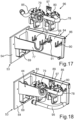
- the carrier has a base body. This base body is in particular designed like a frame.
- the holding arm is arranged so as to protrude from this base body.
- the holding arm has a receptacle for a hose and/or for a portion of the pump on its upper edge.
- a receptacle for a hose and/or for a portion of the pump on its upper edge. This allows the holding arm to hold the hose and/or the pump from above. It is therefore very easy to mount the hose and/or the pump from above on the holding arm. This allows very easy access and yet stable positioning of the additional components mentioned on the holding arm.
- the receptacle is a receptacle that is open at the top. This creates a trough-like or ring-like depression in the upper edge of the holding arm.
- One aspect of the invention relates to a water supply device for a liquid and/or ice dispensing unit of a household refrigeration appliance.
- the water supply device has a carrier. This carrier is intended for carrying at least one pump of the water supply device and/or for carrying at least one hose of the water supply device.
- the carrier also has a holding unit. This is designed to hold a sensor unit of the water supply device in a non-destructively detachable manner.
- the invention therefore forms a multifunctional carrier for a specific assembly of a liquid and/or dispensing unit, namely the water supply device.
- this carrier is intended to accommodate water delivery components such as a pump and/or a hose, and on the other hand, to accommodate a detection device, in particular the sensor unit.
- a wide variety of different components of the water supply device can be arranged on this multifunctional carrier.
- these individual components to be accommodated can also be attached in such a way that their functions are not restricted or do not restrict one another.
- a detachable connection with which a sensor unit can be arranged on this carrier is particularly advantageous. This is because this holding unit enables such a sensor unit to be reversibly attached and removed. This means that the sensor unit can also be removed for maintenance or replacement purposes. In this context, it is then also very easy to carry out this assembly process.
- the carrier is formed in one piece. This means in particular that it is manufactured in a single manufacturing process. In this context, the overall geometry of the carrier is only formed during this manufacturing process. One-piece manufacturing therefore does not mean in particular that individual components of the carrier are first manufactured separately and generated in their basic form and then subsequently joined together, for example by gluing or the like.
- a one-piece formation of the carrier can be carried out, for example, by injection molding. In such an embodiment, the carrier is then an injection-molded component.
- the carrier is in particular made of plastic. This means that it can be provided with a low weight. Furthermore, this material is robust against a wide range of different and highly fluctuating environmental influences and is therefore also wear-resistant.
- a carrier made of metal, particularly a one-piece one, is also possible, particularly as a bent and/or punched and/or embossed component.
- the holding unit has at least one receptacle into which the sensor unit can be inserted at least in part. This improves the positioning of the sensor unit on the holding unit. This enables the sensor unit to be embedded in at least part of the holding unit. In addition, such a concept also enables the sensor unit to be positioned in a way that is protected at least in part.
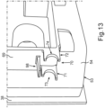
- the holder has at least one holder web. In one embodiment, this has a support bed for the sensor unit.
- a holder web is compact in itself and yet designed to be mechanically stable. As a result, it requires little space and can still bear the corresponding mechanical load.
- the support bed can be designed as a ring section. This enables the sensor unit to be inserted and held in a very secure position.
- the sensor unit in particular with its housing, can thus be placed in a strip-like manner on the support bed.
- a form-fitting fit can also be provided here.
- the holder has at least two separate holder webs. These can each be designed with a corresponding support bed. This enables a further improvement in the secure positioning of the sensor unit. Nevertheless, a very compact and lightweight holding unit is still provided.
- the holding unit has at least one snap element for snapping the sensor unit into place.
- This is an advantageous embodiment for holding the sensor unit in a non-destructive manner. This is because it enables the position of the sensor unit to be fixed particularly securely in the arranged state. On the other hand, it enables quick assembly and disassembly. These advantages of quick assembly and disassembly are particularly important when only one such snap element is provided.
- Such a snap element can be designed as a freely projecting tongue. This can then snap directly onto the housing of the sensor unit when it is arranged in the holding unit. This means that the basic design of this snap connection is also geometrically and functionally very simple.
- the snap element is a separate component from the at least one receiving web. It can also be arranged at a distance from the receiving web. Such a concept improves the mechanically stable mounting, since different components of the holding unit engage directly at different points on the sensor unit.
- the holding unit has a stop wall. This is intended for the abutting positioning of a stop web of the sensor unit. This is particularly the case when the sensor unit is arranged in the assembled end position on the carrier. Such an additional stop connection further improves the positional accuracy of the sensor unit in the holding unit.
- the stop wall is a different component to the snap element and a receiving web. This means that with the direct contact between the stop web and the stop wall, another mechanical connection area can be created between the holding unit and the sensor unit. The position-fixed fit is thus further improved. This enables a very precise end position of the sensor unit on the carrier. This can then also be maintained permanently. This improves the permanently safe and precise detection with the sensor unit.
- the carrier has a base body.
- this base body is formed like a frame.
- the carrier can have a support wall. This is different from the base body. It can be provided that this support wall is arranged so as to protrude from the base body.
- the holding unit is arranged, in particular completely, on the support wall.
- the base body is not impaired by such additional components of the carrier.
- the base body can then be fully coupled to other units, for example an insert part of the household refrigeration appliance.
- no holding units or other components of the carrier are in the way.
- the positioning on the support wall also enables a more exposed attachment of the holding unit. Both accessibility and mechanically stable attachment are improved as a result.
- the support wall is formed as a stiffening strip, in particular one with multiple angles. This increases the stiffness of the support as such. In particular, this can also be used to stiffen the frame-like base body. Because the support wall is also formed as a strip, it is compact in the direction perpendicular to the plane of the base body.
- the strip geometry also means that the dimensions of this support wall perpendicular to its longitudinal axis are smaller than the length along this longitudinal axis.
- the water supply device has at least one sensor unit.
- the sensor unit can be a reed switch.
- a sensor unit is very simply designed and yet permanently functionally reliable and robust in detection.
- such a reed switch can be switched or closed and opened by the influence of a magnetic field. It is therefore very advantageous and easy to arrange such a detection element in a water tank of the water supply device, for example a magnetic float, which floats up or sinks vertically depending on the fill level of the liquid in a water tank. In this way, a simple yet reliable and safe concept for fill level detection can be achieved in interaction between this detection element and the reed switch.
- this sensor unit which can in particular be a level detection sensor unit, detachably on this carrier, it is possible to achieve a precise level determination on a permanent basis.
- the water supply device has a water tank that is separate from the carrier.
- its fill level with liquid, in particular water can be detected with the sensor unit already mentioned.
- the carrier has a counter-coupling device. This is intended for coupling with a coupling device.
- the coupling device is designed in particular on an insert part of the household refrigeration appliance that is separate from the water supply device, so that the carrier can be attached to this insert part.
- the carrier is freely supported and can be attached directly to the insert part.
- a non-destructively detachable connection can also be provided here.
- the carrier thus provides a further additional function. In this context, it is therefore in particular a central component of the water supply device. In this context, in the embodiment mentioned, it is also precisely the central component that is to be mechanically connected directly to this insert part.
- the carrier can therefore also provide and absorb these corresponding holding forces, although it may already be extensively equipped with other components, such as a pump and/or hoses, as well as the sensor unit.
- the carrier has at least one holding arm for holding at least one hose of the water supply device.
- This holding arm is arranged in particular in a freely cantilevered manner.
- the holding arm is arranged protruding from a frame-like base body of the carrier.
- a holding arm provided and oriented in this way allows for simplified assembly of components on the carrier. Nevertheless, the holding arm is arranged in a stable manner, namely on the frame-like base body. Due to the freely cantilevered arrangement, the holding arm is also accessible in many ways and can accommodate such additional components in different positions.
- a holding arm arranged in this way can also be loaded accordingly and serves as an advantageous carrier component for corresponding additional components. Due to the exposed orientation, other parts or components can also be easily handled when attached to the support arm and are therefore easily accessible.
- the carrier has at least one water basin.
- this water basin is integrated in the carrier.
- the water basin is formed in one piece with the carrier.
- Such a water basin or reservoir advantageously makes it possible to prevent undesired water from running into an ice tray of the liquid and/or dispensing unit.
- a water tank of the water supply device is arranged higher in height than this ice tray, water can run or drip from the hoses that lead from the water tank to the ice tray due to the corresponding pressure conditions, in particular hydrostatic pressure, even if the ice tray is already sufficiently full.
- Such undesired running or dripping can lead to undesired overflow of the ice tray.
- the pressure regulation can be improved in such a way that corresponding running or dripping of liquid into the ice tray can be better avoided.
- the larger volume of the water basin compared to the connecting hoses advantageously results in a corresponding pressure equalization on the way between the higher water tank and the lower ice bowl, so that the dripping into the ice bowl, as already explained, can be avoided.
- the water basin can therefore also be referred to in this context as a pressure equalization chamber or dosing chamber.
- this water basin is integrated into the carrier, which also reduces the number of components. This is because there is no need to provide a separate water basin, which would have to be mounted on the carrier using a corresponding assembly process.
- the water basin also represents a holding component of the carrier.
- the water basin can be integrated into a holding structure of the carrier, for example.
- This holding structure serves on the one hand to accommodate further components of the water supply device, such as a pump and/or at least one hose, but on the other hand also serves to temporarily store the water on the way from the water tank to an ice tray.
- such a water basin is thus integrated into such a holding structure, in particular also into a specifically designed holding arm.
- this water basin can be arranged directly on a base body, in particular a frame-like base body, of the carrier.
- the water basin can be oriented so as to protrude freely from this base body. This means that the advantages already explained above for the advantageous embodiment with the holding arm can also be achieved with this water basin.
- the holding arm can be provided in addition to the water basin. These components can then be arranged at a distance from one another, in particular cantilevered from the base body. In this context, they can be arranged in the same direction from the base body. In this way, in an advantageous embodiment, a free space or an air space is formed between the holding arm and the water basin, in which additional components of the water supply device can be arranged very compactly and yet highly functionally. This is because at least one pump and/or at least one hose can then be arranged and held in this free space in a compact and yet positionally secure manner. In this context, it is also particularly advantageous that these additional components are arranged hanging in the free space.
- the holding arm having corresponding receptacles, in particular recesses, into which a hose can be inserted, for example.
- the water basin can also have such a receptacle, in particular an opening, at least on one boundary wall, into which at least one hose can be inserted and received. This allows these additional components to be attached in a suspended manner to the holding arm and/or the water basin.
- the carrier has at least one, in particular several, separate holding claws.
- These holding claws are intended for holding one or more hoses of the water supply device and/or at least one pump of the water supply device.
- a holding claw is a component that at least partially grips a hose and/or a pump.
- a holding claw thus has at least two holding fingers that partially grip the object to be held.
- a holding claw can be a freely projecting web, at the end of which these claw fingers are arranged. Such holding claws are then arranged in an exposed manner and a particularly simple assembly scenario is possible. Due to the advantageous accessibility, a hose and/or a pump can then be very easily inserted into the holding claw.
- the holding claw is designed so that a hose and/or part of a pump is held in the holding claw in a form-fitting manner.
- a force-fitting attachment can also be provided.
- a clamping force can then be formed with which the hose and/or the part of the pump are held in the holding claw. This enables a particularly stable and secure fit. Even when the water supply device is in operation, in particular when a pump is in operation, the respective position is then permanently held securely, even if vibration forces occur due to the operation of the pump.
- these preferably several holding claws are integrated into a holding arm.
- one holding claw or several holding claws can be integrated into a boundary wall of the water basin.
- a holding claw is arranged in the free space as explained above and as it can be formed between a holding arm and the water basin in the carrier. This further improves the secure and simple installation of these additional components in this free space between the holding arm and the water basin.
- a further aspect of the invention relates to a liquid and/or ice dispensing unit for a household refrigeration appliance.
- the liquid and/or ice dispensing unit can have a water supply device according to the above-mentioned aspect or an advantageous embodiment thereof.
- the liquid and/or ice dispensing unit can additionally have a dispensing device. This is for direct dispensing of liquid and/or ice.
- This dispensing device can be arranged, for example, on a door of the household refrigeration appliance. It can be arranged in a niche in the door that is open on the outside.
- the liquid and/or ice dispensing unit can also have an ice production unit. This is a separate unit from the water supply device of the liquid and/or ice dispensing unit.
- the liquid and/or ice dispensing unit can also have an ice tray. With this ice tray, water introduced can be frozen into ice cubes, for example.
- the liquid and/or ice dispensing unit can also have a conveyor unit with which ice produced and temporarily stored in a storage trough, such as ice cubes or crushed ice, can be conveyed to the dispensing device.
- a conveyor unit with which ice produced and temporarily stored in a storage trough, such as ice cubes or crushed ice, can be conveyed to the dispensing device.
- a further aspect of the invention relates to a household refrigeration appliance.
- the household refrigeration appliance has a water supply device according to the above-mentioned aspect or an advantageous embodiment thereof.
- the household refrigeration appliance can also have a liquid and/or ice dispensing unit.
- the water supply device has a water tank. This can preferably be reversibly removed and reinserted. This means that it can be filled with liquid, in particular water, by a user external to the household refrigeration appliance. For example, this can be done at a water tap.
- This method makes it particularly easy to detect specific fill levels in the water tank. It is no longer necessary to provide several separate sensor units, each of which detects different, discrete fill levels. In particular, it is provided that only a single sensor unit is provided. It is particularly advantageous with the method to detect a fill level of liquid in a water tank that is not equal to the maximum fill level and/or that is not equal to the empty tank. Because the proposed new concept with the sensor unit directly detects a fill level that is not equal to the empty water tank, other fill levels, in particular an empty water tank, can be determined by specifically evaluating parameters of operating units of the water supply facility. In particular, the empty water tank and thus an empty fill level no longer have to be detected directly with a sensor unit, but this can be done indirectly using the proposed method.
- the reaching of the empty fill level is calculated based on a liquid level in the water tank that is different from the empty fill level and additional information from operating parameters, in particular at least one pump of the water supply device. This also makes it possible to detect the empty fill level more precisely.
- inaccuracies in the fill level detection can occur due to the size and also the at least partial immersion in the water. This can be avoided by the method and thus the empty level in the water tank can be recorded or calculated more precisely.
- the volume of the water tank is known, in particular also predetermined and stored in a storage unit of the water supply device, it can also be determined via the recorded current operating times and/or delivery quantities how much liquid has been pumped out of the water tank since the time of detection of the sensor device leaving the detection range by the detection element, it can also be determined very easily and yet precisely and quickly when the liquid empty level in the water tank is reached.
- the sensor unit is positioned in such a way that a fill level is detected by the interaction of the detection element and the sensor unit, which is different from the maximum fill level and different from the liquid empty level.
- a fill level is detected by the interaction of the detection element and the sensor unit, which is different from the maximum fill level and different from the liquid empty level.
- the reference operating time indicates the period of time which, based on the volume of the water tank and the operating mode of the pump, indicates the period of time that passes from the detection of the sensor unit leaving the detection range until the empty level in the water tank is reached.
- the reference delivery rate so that here too, due to the known volume of the water tank and the knowledge of the amount of water still in the water tank when the detection element detects that the sensor unit has left the detection range, it is also possible to determine exactly when the empty level in the water tank is reached.
- the detection element is a detection element partially immersed in the water in the water tank.
- the sensor unit is positioned in the vertical direction in such a way that the detection area is left when the sub-area of the detection element immersed in the water is at a predetermined distance from the inside with a lower end viewed in the vertical direction. of the bottom of the water tank or is arranged so as to sit on this inside.
- this lower end is still spaced from the bottom of the water tank by a value of between less than 2 millimeters, in particular between less than 2 millimeters and more than 0.5 millimeters, and this lower end is therefore not yet sitting on this bottom, a very precise level for an intermediate fill level can also be detected here, from which a very simple check and calculation can then be carried out on the basis of the preferably existing parameters set out above and their evaluation as to when exactly the empty fill level in the water tank is reached.
- the sitting down it is also possible for the sitting down to take place and thus exactly this state and this point in time to occur when the detection element detects that it has left the detection range of the sensor unit.
- the water supply device has a carrier for carrying at least one pump of the water supply device and/or for carrying at least one hose of the water supply device.
- the carrier has at least one holding structure for carrying the at least one pump of the water supply device and/or for carrying the at least one hose of the water supply device.
- This holding structure has at least one water basin. It is therefore preferably provided in this water supply device that a water basin is provided on the carrier. In an advantageous embodiment, this allows water to be transported by water between a water tank of the water supply device and Such an intermediate reservoir for water can be provided at an outlet.
- this can prevent undesired dripping of liquid from this outlet into, for example, an ice tray of the liquid and/or ice dispensing unit. This prevents undesired overflow of the ice tray and/or extensive freezing of the ice tray.
- the water basin is integrated into the support structure.
- the support structure is arranged in a freely cantilevered manner from a base body of the carrier, in particular a frame-like base body.
- At least one holding claw in particular several holding claws, is arranged on the water basin for holding hoses and/or at least one pump of the water supply device.
- this at least one holding claw is integrated freely cantilevered on the water basin. It can be provided that this at least one holding claw extends in a free space between a holding arm of the carrier and the holding structure which is separate and spaced apart from it.
- the holding claws have claw openings. In one embodiment, these are oriented upwards in the height direction of the water supply device. This makes it particularly easy to insert a hose and/or a pump from above. This enables a very simple assembly scenario with clear assembly steps to be carried out.
- a pre-assembly module is created with at least one hose and at least one pump, which are then already pre-assembled with one another. This pre-assembly module can then be very easily inserted into this at least one holding claw from above.
- the water basin has a boundary wall, in particular a boundary wall that faces a support arm of the carrier.
- this boundary wall has a passage for a hose.
- the passage is on an upper edge of the boundary wall arranged. It is designed in particular as a recess that is open at the top for receiving and guiding a hose through. This also provides a simple holding and mounting scenario for a hose that is to be mounted directly on this boundary wall. This makes it very easy to insert and remove this hose from this passage. Nevertheless, a stable fit of the hose on this boundary wall is achieved.
- the household refrigeration appliance also has an inner container.
- the inner container is a separate component from the outer housing.
- the inner container is accommodated in the outer housing.
- the inner container delimits at least one receiving space for food.
- the receiving space is a component of the household refrigeration appliance.
- an intermediate space is formed between the outer housing and the inner container. This is intended for filling with thermally insulating material of the household refrigeration appliance.
- the household refrigeration appliance also has an insert part. This can also be referred to as a backing part.
- the insert part is arranged in the intermediate space in the region of an opening formed in a wall of the inner container.
- the insert part has a coupling device.
- the household refrigeration appliance also has a water supply device.
- the water supply device is in particular a component of a liquid and/or ice dispensing unit of the household refrigeration appliance.
- the water supply device has a counter-coupling device. This is intended for coupling with the coupling device when the water supply device is mounted or is mounted on the insert part.
- the coupling device and the counter-coupling device are designed in such a way that at least one component, in particular a carrier, of the water supply device is arranged freely on the insert part and is also arranged in the receiving space. This means that with this specific structure, this at least one component of the water supply device is held without additional support and/or support below the component only by the holding forces between the coupling device and the counter-coupling device.
- this component in particular the water supply device, is freely cantilevered. extends into the receiving space and this is held by the direct mechanical coupling between the coupling device and the counter-coupling device.
- This enables a particularly advantageous assembly concept for the water supply device. This is because a specific insert part serves as the component to which the water supply device can be directly mounted.
- the water supply device it is also possible for the water supply device to be arranged very specifically in the household refrigeration appliance and to be held permanently. Corresponding weight forces and also leverage forces that act on the insert part can be absorbed accordingly.
- This also makes it possible, in a particularly advantageous manner, for other components of the liquid and/or ice dispensing unit, which are also arranged adjacent to the water supply device and/or are directly connected to it, to be easily removed without damaging the holding connection between the water supply device and the insert. Even components that are arranged vertically below the water supply device and/or are removed below the component that is directly connected to the insert do not result in this connection interface, in particular the attachment interface, between the insert and the component of the water supply device being damaged.
- the coupling device and the counter-coupling device are mechanically so stable and robust that the position of the water supply device in its freely cantilevered extension and in its freely supporting arrangement on the insert is also permanently maintained.
- the coupling device extends through the opening into the receiving space. This means that it is also arranged in a locally exposed manner, so that direct coupling with the counter-coupling device is easier. Especially when the water supply device, in particular the said component, is brought to the insert part and is directly connected to it, this position of the coupling device makes it easier to carry out the particularly mechanical coupling process and to reach the coupled end position precisely.
- the coupling device has at least one coupling rail.
- the component can be directly attached to this.
- a coupling rail is in particular an elongated component. This allows an increased mechanical coupling with the counter-coupling device to be achieved. This provides improved support for a hanging connection between the coupling device and the counter-coupling device. This is because the weight forces of the component can be transferred to the coupling device over a larger area or absorbed by it.
- such a rail can be relatively long in one spatial direction, but is relatively compact in the other two spatial directions. A space-saving arrangement can therefore also be achieved at least in these other two spatial directions.
- the coupling device has several, in particular two, separate coupling rails. This can improve the mechanically stable connection with the counter-coupling device. The absorption and dissipation of corresponding weight forces and lever forces is thereby further improved.
- At least one coupling rail can be L-shaped when viewed in cross-section.
- the cross-section is preferably formed perpendicular to the longitudinal axis of the coupling rail.
- this shape of a coupling rail creates a simple geometry.
- it enables quick and yet stable coupling with a counter-coupling device.
- hanging the counter-coupling device from above in such a shaped coupling rail is easy and safe. This prevents the counter-coupling device from slipping or slipping out of the coupling rail.
- hanging the counter-coupling device from above in such a coupling rail also enables improved absorption of weight forces and lever forces.
- the coupling rail is oriented in its L-shape in such a way that one L-leg points upwards in the vertical direction and is cantilevered upwards. This creates a receiving area into which the counter-coupling device can be inserted. This further improves a hanging connection in particular, as the upwardly projecting leg of the L-shape prevents the counter-coupling device from slipping out.
- the coupling device has at least one positioning dome. This can be inserted into a dome receptacle of the counter-coupling device. By inserting them into one another, at least one plug connection is created. This additionally supports the positioning accuracy of the coupling device and the counter-coupling device relative to one another. In addition, this also enables easier assembly, because this positioning dome and the dome receptacle can also provide assembly coding.
- the positioning dome is additionally designed as a screw dome. This allows an additional screw connection to be formed between the insert part and the component of the water supply device that is to be directly connected to it.
- the screw connection improves the permanent, precise positioning of the component on the insert part and thus also of the water supply device on the insert part.
- the coupling connection between the coupling device and the counter-coupling device can be released without causing any damage.
- the component of the water supply device which is in particular attached directly to the insert, can be a carrier in one embodiment. This can be designed to carry at least one pump of the water supply device and/or to carry at least one hose of the water supply device. This means that in a In this embodiment, a central component of the water supply device is also the component that is directly connected to the insert. This robust component not only serves to accommodate other components of the water supply device, but also represents the interface to the insert.
- the insert has at least one retaining element. This extends in particular into the receiving space.
- the retaining element extends over the clear width of the opening, so that the retaining element overlaps with those surface areas of the wall of the inner container that border on or delimit the opening.
- This enables the insert to be attached to the wall of the inner container in the area of the opening in a very simple manner. In particular, this enables a self-retaining connection of the insert to the wall.
- the retaining element is integrated in the insert.
- the insert can be a plastic part, for example. It can be an injection-molded component, for example. By forming the retaining element in one piece with the insert, the number of components is reduced.
- the retaining element can be formed mechanically stable with the insert. This allows corresponding forces to be absorbed and position tolerances of the retaining element can be avoided.
- At least one holding element is designed as an elongated holding rail.
- this elongated holding rail can be formed on a base body of the insert part, so that a receiving groove for the surface area is formed between the holding rail and the base body. The surface area thus dips into this receiving groove, so that the insert part is stable. As this surface area is surrounded on both sides by partial areas of the insert part, the insert part can also be stable on the wall.
- This embodiment makes it particularly easy to install the insert part. This is because a simple relative movement between the insert part and the wall allows the surface area to be pushed into this receiving groove, thus creating the desired final position of the insert part on the wall in the area of the opening in a very targeted manner. In addition, this geometry also prevents the insert part from becoming undesirably detached from the wall.
- the opening preferably has at least one threading area.
- This threading area has a larger clear width than an opening area of the opening adjacent to the threading area.
- This locally limited widening of the opening makes it possible to achieve a particularly simple installation scenario for the insert on the wall.
- This makes it very easy for the insert to be introduced into the opening from one side of the wall in such a way that the retaining rail is introduced into the threading area from one side of the wall and can thus be moved through the opening to the other side of the wall.
- the clear width of the threading area is at least as large as the distance between a free edge of the holding element and an opposite area of the insert.
- this clear width of the threading area is at least as large as the distance between a free edge of the holding element and another free edge of another holding element.
- one end of the holding element is widened, particularly when viewed in the direction of the longitudinal axis of the holding element.
- this end is designed as a threading end.
- This widening of the end makes it possible to carry out the assembly process as explained above in a very simple manner. This is because a funnel-like inlet can be created at this end of the holding element. This makes it easier to guide the holding element through the opening from one side of the wall, particularly in the threading area. Jamming or spreading or unwanted impacts are thus better avoided.
- This widening makes it easy to accommodate the particularly abrupt transition between the threading area and the further opening area. This also makes it easier to insert the surface area further into the receiving groove when the insert part is moved further relative to the wall.
- One aspect of the invention relates to a household refrigeration appliance with an outer housing and with an inner container which is accommodated in the outer housing and which delimits a receiving space for food.
- the household refrigeration appliance has an intermediate space which is formed between the outer housing and the inner container and which is intended to be filled with thermally insulating material.
- the household refrigeration appliance has an insert which is arranged in the intermediate space in the region of an opening through a wall of the inner container.
- the insert has a base body, in particular a plate-like one, which has at least one hole onto which at least one pipe socket of the insert which projects into the intermediate space is formed.
- the pipe socket is formed as a coupling socket for a hollow part of the household refrigeration appliance. This makes it possible for the insert to be used as a multifunctional component.
- the coupling socket can have a coupling structure. This is intended for coupling, in particular mechanically, with an additional part.
- the coupling structure can have a thread. It can also have a snap-on device or a bayonet device.
- a plug-in coupling for easy connection to the additional part is also possible. This is advantageous if an extension is to be formed as a hollow part on the coupling socket, so that a laying channel for another component is formed through the coupling socket and the hollow part, in particular an empty pipe.
- the additional component can be a hose, for example. However, it is also possible for a hollow part in the form of a hose to be coupled directly to the coupling structure. The medium, for example water, then flows directly in this channel. An additional empty pipe in which the separate hose is then laid is then not required.
- the hollow part is an empty pipe for holding a separate hose.
- the hollow part can also be a hose itself. This allows liquids such as water to be directed in a more targeted manner.
- the coupling socket is curved in an arc shape at least in some areas. This allows a hose that is guided through the hole in the base body to be laid without kinks. This also makes it possible to continue the hose into the hollow part without kinks.
- the insert part has the plate-like base body, which has at least one further hole, onto which at least one pipe socket of the insert part is formed, which extends into the intermediate space and is formed as a coupling socket for another hollow part of the household refrigeration appliance.
- the hollow part is an empty pipe for holding a cable. This also allows electrical elements to be laid and routed safely.
- the additional hole is formed higher on the base body than the hole, as viewed in the vertical direction of the household refrigeration appliance. This also prevents, for example, the situation in the event of a leak in the lower Hole through which liquid medium can be conducted, the electrical components may be affected.
- the hollow part is arranged on an inner side of a vertical side wall of the outer housing facing the intermediate space. This achieves an advantageous position and enables short installation paths to the devices of the household refrigeration appliance to which water is to be supplied.
- spacers are arranged on the inside of the side wall, on which the hollow part is arranged. This enables stable positioning and yet avoids long linear contact with this side wall. This has advantages in terms of thermal insulation.
- the hollow part can then be embedded circumferentially in the thermal insulation material that is arranged in the intermediate space.
- the household refrigeration appliance has at least one hose that extends through the hole in the coupling nozzle and from there protrudes into the intermediate space, the hose being laid upwards in the height direction at least after the coupling nozzle in the intermediate space and being laid in a receiving area between a ceiling wall of the outer housing and an intermediate plate of the household refrigeration appliance arranged adjacent thereto.
- This also results in a short laying path.
- existing installation space in this ceiling area of the household refrigeration appliance is used in order to be able to lead the hose in particular to a door of the household refrigeration appliance.
- the hose can also be laid easily and quickly into the door via this ceiling area and a hinge with which the door is arranged on the housing.
- no thermally insulating material is arranged in the receiving space.
- the intermediate plate has, in particular, groove-like receptacles in which the hose is laid. This also ensures that the hose is positioned precisely.
- a gap is formed between the intermediate plate and a ceiling wall of an inner container of the household refrigeration appliance, which gap contains thermally insulating material.
- a further aspect of the invention relates to a method for mounting a domestic refrigeration appliance component of a domestic refrigeration appliance on an insert part of the domestic refrigeration appliance.
- a water supply device in particular a carrier thereof, for a liquid and/or ice dispensing unit of the domestic refrigeration appliance is mounted on the insert part as a domestic refrigeration appliance component.
- the insert part is mounted in an intermediate space between an outer housing of the domestic refrigeration appliance and a separate inner container of the domestic refrigeration appliance in an area of an opening in a wall of the inner container.
- the insert part is coupled with a coupling device to a counter-coupling device of the water supply device, so that at least one component of the water supply device is arranged freely supporting on the insert part and is arranged in the receiving space.
- the water supply device in particular a carrier of this water supply device, is thus directly attached freely supporting to the insert part.
- the water supply device has a housing. Components for conveying water are arranged in this housing. The components are part of the water supply device.
- the housing has a housing cover.
- the housing also has a base module.
- the base module is arranged on the housing cover with a non-destructively detachable connection.
- the housing is made up of two separate components, access to the components in the housing is very easy. This means that the base module and/or the housing cover, for example, can be reversibly removed and the components in the housing are freely accessible. Because the housing cover is directly connected to the base module, in particular with a non-destructively detachable connection, these components can also be easily separated from one another and reassembled.
- the base module is designed as a single piece. This reduces the number of components. In particular, if the housing needs to be opened, it is very easy to remove just the base module as a single piece component. This also reduces the assembly and disassembly effort.
- the base module in a connected end position of the base module with the housing cover, is coupled to the housing cover with at least one snap connection.
- a snap connection is a mechanically simple connection that can be reversibly released and recreated. It is permanently highly functional and robust. Any forces that occur can be easily absorbed.
- the snap connection also enables the end position between the housing cover and the base module to be held in a very fixed position.
- the housing cover has at least one guide element.
- a counter-guide element arranged on the base module can be coupled to this. This enables a relative movement, in particular a linear one, between the base module and the housing cover to be guided in a particularly simple manner. This enables a clamp-free and jerk-free connection between the housing cover and the base module.
- the base module can also be mounted very easily on the housing cover. This is because in the coupled state, the base module can move in a straight line relative to the housing cover, which is then also safely guided to reach the end position. This enables a very low-complexity assembly scenario.
- a guide element is formed on an outside of the housing cover. This guide element is exposed and therefore very easy for a user to see. This makes coupling the counter-guide element with the guide element very simple and accurate. In addition, the relative movement between the counter-guide element and the guide element coupled to it can be observed over almost the entire assembly path. The assembled final state is then also easily recognizable visually. In particular, if a snap connection is provided that holds the final position between the base module and the housing cover, the final position can also be clearly perceived through haptic feedback.
- a guide element is designed as a guide runner.
- a step is formed in the side wall of the housing cover. This guides the linear assembly direction in a particularly advantageous manner. This is because such a step predetermines the movement path of the counter-guide element on the guide element in at least two spatial directions.
- the guide element extends over at least 70 percent, in particular at least 90 percent, of the length of a side wall.
- the side wall is a long side wall of the housing cover.
- a long side wall is in particular a wall oriented in the vertical direction that is longer than other adjacent side walls of the housing cover oriented in the vertical direction.
- the housing cover is designed like a cuboid.
- such long guide elements ensure that the entire assembly path between the currently coupled state and the end position between the base module and the housing cover is guided very evenly.
- a contact between the guide elements and the counter-guide element can still be maintained in the corresponding end position. Therefore, the end position between the components mentioned is also supported by this length of the guide element.
- the base module has a guide part.
- the guide part is intended to guide a water tank of the water supply device when the water tank is brought to the housing.
- this guide part is thus integrated in the base module. This means that it is manufactured in one piece with it. This also makes it easier to assemble and find the end position of the water tank in the water supply device. This enables the water tank to be moved to the end position in a very targeted manner.
- This guided movement of the water tank is particularly advantageous if this assembly process also automatically involves a coupling between a hose and/or a nozzle of the water tank and a hose and/or a nozzle in a unit of the water supply device adjacent to the water tank.
- the guide part is designed as a guide tongue. This means that it is arranged and oriented in a very exposed manner. This enables very simple and clear coupling with the water tank. This also improves the guidance of the water tank during the assembly process. Tilting or This makes it easier to prevent the water tank from slipping out of the coupled situation with the guide tongue.
- the guide part is arranged protruding from a side wall of the floor module. This exposed position and orientation makes it particularly easy to couple the water tank to it and to safely guide the assembly movement into the final position.
- the guide part can be arranged in a freely cantilevered manner. This supports the advantages mentioned above.
- the base module has a mounting plate.
- the mounting plate is intended for mounting the water tank.
- This mounting plate is oriented in such a way that the water tank can be mounted laterally and directly adjacent to the housing of the water supply device or to the housing of a free assembly of the water supply device.
- the mounting plate is preferably dimensioned in such a way that it corresponds to at least 90 percent of the surface area of the base of the water tank. This means that the water tank can be mounted with its base on the mounting plate, in particular over its entire surface.
- the guide part is integrated into this mounting plate. This means that the mounting plate and the guide part are formed as one piece. In one embodiment, the guide part can protrude upwards above the top of the mounting plate when viewed in the vertical direction. This concept stabilizes this guide part by integrating it into the mounting plate. This prevents damage to the guide part in the event of a collision or other force being applied.
- such a concept also prevents any additional components that may be located externally to the water supply system and on which the floor module is placed from being damaged, for example scratched, when the water tank is installed. This is because the installation plate forms an intermediate part between this additional Component, for example a shelf of the household refrigeration appliance, such as a glass plate, and the water tank.
- a further aspect of the invention relates to a household refrigeration appliance with a water supply device according to the above-mentioned aspect or an advantageous embodiment thereof.
- a household refrigeration appliance is designed in particular for storing and preserving food.
- a household refrigeration appliance can be, for example, a refrigerator or a freezer or a fridge-freezer combination appliance. It can have an outer housing and an inner container arranged therein. In one embodiment, the inner container can delimit at least one receiving space for food. Such a receiving space can be, for example, a refrigerator compartment or a freezer compartment.
- a household refrigeration appliance can have at least one door that is movably arranged on the body of the household refrigeration appliance. In this door, for example, a dispensing device of the liquid and/or ice dispensing unit of the household refrigeration appliance can be arranged.
- a further aspect of the invention relates to a method for assembling a water supply device, in particular according to an above-mentioned aspect or an advantageous embodiment thereof.
- the base module is mounted in a first mounting direction on the housing cover of the housing.
- a water tank of the water supply device which is separate from the housing, is mounted in a second mounting direction oriented perpendicularly to this first mounting direction.
- the water tank is also guided in particular.
- the water tank is guided through this second mounting direction to a subassembly, which is in particular enclosed by the housing.
- the water tank is arranged outside this housing of the subassembly. In the final position, it borders directly on the side of the housing of the subassembly.
- One aspect of the invention relates to a liquid and/or ice dispensing unit of a household refrigeration appliance.
- the liquid and/or ice dispensing unit has a water treatment device according to an above-mentioned aspect or an advantageous embodiment thereof.
- Embodiments of an independent aspect relating to a water supply device are to be regarded as advantageous embodiments of the other independent aspects.
- top, bottom, front, bottom, horizontal, vertical, depth direction, “width direction”, “height direction” indicate the positions and orientations that apply when the device or household appliance is used and positioned as intended.
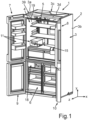
- FIG.1 an embodiment of a household refrigeration appliance 1 is shown in a perspective view.
- the household refrigeration appliance 1 is designed for storing and preserving food.
- the household refrigeration appliance 1 can be a refrigerator or a freezer or a fridge-freezer combination appliance.
- the household refrigeration appliance 1 has a housing 2. This can also be referred to as a body.
- the housing 2 has an outer housing 3.
- the outer housing in particular also has vertical side walls 3a and 3b. It also has a ceiling wall, not shown here.
- an intermediate plate 3c is shown in one embodiment. This intermediate plate 3c is arranged between the top wall of the outer housing 3 and a top wall of an inner container 4 of the household refrigeration appliance 1.
- a receiving space is formed between the top wall of the outer housing 3 and the intermediate plate 3c, in which Components can be arranged.
- Thermally insulating material is arranged in the space between the intermediate plate 3c and the top wall of the inner container 4.
- receptacles 3d, 3e are formed on an upper side of the intermediate plate 3c facing the top wall of the outer housing 3. In particular, these can be receptacles 3d, 3e for at least one hose.
- the housing 2 also has an inner container 4.
- the inner container 4 is separate from the outer housing 3.
- the inner container 4 is accommodated in the outer housing 3.
- the inner container 4 defines with walls at least one receiving space 5 for food.
- the receiving space 5 can be a refrigerator compartment.
- the household refrigeration appliance 1 can have a further receiving space 6. This can be a freezer compartment.
- the household refrigeration appliance 1 has at least one door 7.
- two doors 7 and 8 are provided, which close the receiving space 5 at the front.
- further doors 9 and 10 are provided, which close the preferably present further receiving space 6 at the front.
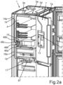
- the household refrigeration appliance 1 preferably has a liquid and/or ice dispensing unit 11. This is intended to dispense liquids, such as drinks, and/or ice. As can be seen in the exemplary embodiment and in the further perspective in Fig. 2a As shown, this liquid and/or ice dispensing unit 11 has a dispensing device 12. In this embodiment, this is arranged in the door 7. A niche 13 is preferably formed on an outer side 7a of the door 7. A receptacle, such as a drinking glass, can be placed in this. Liquid is then dispensed by operating the dispensing device 12.
- the dispensing device 12 can be connected to a water supply device 15 in a fluid-conducting manner by means of at least one line 14.
- the water supply device 15 is arranged here in the receiving space 5. It is in particular a component of the liquid and/or ice dispensing unit 11.
- the water supply device 15 can be connected via a further line 16 to a further device 17 arranged in the receiving space 6. This can be used to produce and provide very cooled liquid or ice, for example. Water which passes from the water supply device 15 to the device 17 via this line 16 can then be very cooled, in particular also frozen, in the receiving space 6, which is preferably designed as a freezer compartment.
- an ice tray which can be part of the device 17, for example, can be filled with the water from the water supply device 15 and then corresponding ice can be produced. In one embodiment, this ice can then also be provided via a specific compartment, for example a compartment 18, as in Fig.1 shown.
- the device 17 can be an ice producing device or an ice maker of the liquid and/or ice dispensing unit 11.
- FIG. 2a the household refrigeration appliance 1 is shown from the side with the outer casing 3 removed and the inner container 4 shown transparently on this side wall so that the components can be seen as they have been explained.
- Fig. 2b is, in a corresponding representation as in Fig. 2a , another embodiment of a household refrigeration appliance 1 is shown.
- the device 17 is arranged in the receiving space 5, in particular in an upper corner area.
- the device 17 is thermally insulated from the rest of the receiving space 5.
- ice can also be automatically dispensed from the device 17 to the dispensing unit 12, for example by means of an ice chute arranged in the household refrigeration appliance 1.
- Fig.3 is an enlarged view of a section of Fig.1 shown.
- the partial area in which the water supply device 15 is arranged is shown here.
- a wall 19 of the inner container 4 is shown here.
- the water supply device 15 is arranged adjacent to this vertical wall 19.
- a partition wall 20, such as a shelf, is arranged below the water supply device 15.
- the water supply device 15 preferably has a subassembly 21.
- the subassembly 21 is in particular equipped with components such as at least one hose and/or at least one pump. It is therefore intended in particular for conveying or forwarding liquid, in particular water.
- the subassembly 21 has a housing 22.
- this housing 22 has a housing cover 23.
- this housing 22 has a base module 24.
- the partition wall 20 is arranged directly below the water supply device 15. In particular, it can be removed separately from the water supply device 15. As a result, it can be easily cleaned independently of the water supply device 15.
- the water supply device 15 has a water tank 25 in one embodiment.
- the water tank 25 is separate from the subassembly 21. It is therefore also arranged outside the housing 22.
- the water tank 25 in its shown end position is arranged immediately adjacent to and subsequent to the subassembly 21. It is arranged in front of the subassembly 21 in the depth direction (z direction), in particular of the household refrigeration appliance 1.
- the water tank 25 is arranged so that it can be removed without causing any damage. It can therefore be reversibly removed and reinserted. In particular, it can therefore be removed by a user and filled manually, for example at a water tap.
- Fig.4 is a perspective view of the arrangement according to Fig.3 shown, where in Fig.4 the water tank 25 is removed.
- the base module 24 has in particular a base unit 26. This limits the housing 22 at the bottom.
- This base unit 26 is also directly connected to the housing cover 23.
- the base module 24 has a guide part 27.
- the guide part 27 is intended to guide the water tank 25 during assembly and disassembly. This ensures the linear assembly direction of the water tank 25
- This guide part 27 can be provided as a freely projecting guide tongue. It can be formed integrally on a side wall 28 of the base unit 26 and arranged to protrude from there.
- this floor module 24 can have a storage plate or a mounting plate 29. This is intended to ensure that the water tank 25 in its final position, as shown in Fig.3 shown, is placed thereon. As a result, components such as the partition wall 20 are not directly contacted by the water tank 25.
- the guide part 27 can also be formed in one piece with this mounting plate 29. It is thus integrated into this mounting plate 29. In the vertical direction (y-direction) this guide part 27 preferably protrudes upwards relative to the top of the mounting plate 29.
- the mounting plate 29 can have a raised stop 30 on the front. This prevents the water tank 25 from sliding forwards in its final position, as shown in Fig.3 shown, prevented.
- this specific guidance scenario also makes it possible for a coupling nozzle of the water tank 25 to be automatically coupled to a coupling nozzle 31 of the subassembly 21 when the water tank 25 is attached to the end position.
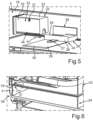
- the housing cover 23 is connected to the base module 24 by a detachable connection. As shown in Fig.5 can be seen, the base module 24 can be separated from the housing cover 23.
- a guide element 34 is formed on an outer side 32 of a side wall 33 of the housing cover 23.
- the guide element 34 is here integrated into this outer side 32.
- the guide element 34 can be formed as a guide skid. This also means that it can be formed, for example, as a step in this outer side 32.
- the side wall 33 here represents a longitudinal side wall of the housing cover 23.
- a counter-guide element 35 of the base module 24 can be coupled to this guide element 34, so that the relative movement between the housing cover 23 and the base module 24 is guided.
- a corresponding guide element can also be formed on the opposite longitudinal side wall of the housing cover 23. This can then be coupled to a counter-guide element 36 in order to be able to guide the relative movement.
- the base module 24 is formed in one piece. It can, for example, be an injection-molded component.
- the assembly direction P1 is shown in which the floor module 24 is to be moved when it is moved from the end position according to Fig.4 is to be removed and removed from the housing cover 23. If the base module 24 is to be reinstalled, it must be coupled to the housing cover 23 opposite to the installation direction P1 and placed in the final position according to Fig.4 In particular, the water tank 25 can then be pushed on in a perpendicular mounting direction P2 until it reaches the Fig.3 has reached the final position shown.
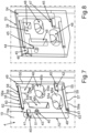
- Fig.6 is a perspective sectional view of the arrangement according to Fig.4 shown, where in Fig.4 the section line VI-VI is shown.
- a snap connection 37 can be formed in one embodiment. With this snap connection 37, in particular, the end position of the base module 24 with the housing cover 23 can be held better. Undesirable slipping of the base module 24 can thus be better prevented.
- the snap connection 37 can be overcome by overcoming a force threshold when moving the base module 24 out of the end position. In this respect, in one embodiment, no additional release tool or the like is required in order to be able to release the snap connection 37.
- the household refrigeration appliance 1 has an insert part 38, as shown in Fig.7 shown in the assembled final position.
- the insert part 38 can also be referred to as a backing part.
- This gap 39 is formed between the outer housing 3 and the inner container 4.
- the gap 39 is preferably filled with a thermally insulating material.
- the thermally insulating material can comprise insulation foam and/or vacuum insulation panels.
- this wall 19 has an opening 19a.
- the insert part 38 is arranged in the area of this opening 19a. It extends with partial elements into the receiving space 5.
- the insert part 38 is preferably a one-piece component. It is made in particular from plastic. It can be an injection-molded component.
- the insert part 38 is provided here in the exemplary embodiment for direct coupling to the water supply device 15. It is designed in particular so that the water supply device 15 can be coupled directly to this insert part 38. In particular, this coupling connection is designed so that the water supply device 15 can be attached to this insert part 38 in a freely supporting manner. The water supply device 15 can therefore also be attached to this insert part 38 and then extends freely cantilevered into the receiving space 5.
- Fig.5 This cantilevered attachment, there of the subassembly 21, to the insert 38 is shown.
- Fig.4 a corresponding illustration is shown. It is therefore not necessary for the water supply device 15 to be supported downwards. Rather, this coupling connection between the insert part 38 and at least one specific component of the water supply device 15 can absorb the corresponding weight forces and lever forces.
- the insert part 38 preferably has a coupling device 40 for this purpose.
- This coupling device 40 is provided for direct coupling with a counter-coupling device, as is formed on the water supply device 15.
- the coupling connection here is a purely mechanical coupling connection.
- the in the exemplary embodiment, coupling device 40 can have a coupling rail 41.
- a first, in particular upper, coupling rail 41 and a second, in particular lower, coupling rail 42 are provided here.
- these coupling rails 41 and 42 can be L-shaped in a cross section perpendicular to their longitudinal axes.
- the water supply device 15 can be arranged directly, in particular suspended, on these coupling rails 41 and 42.
- the coupling device 40 can also have at least one positioning dome 43. This is for inserting a dome receptacle 44, as shown in Fig.8 shown.
- This positioning dome 43 can be a screw dome in one embodiment. This allows a screw connection to be provided at the location of the positioning dome and the inserted dome receptacle 44.
- the coupling device 40 is provided with a counter-coupling device 45, as shown in Fig.8 shown, detachably connected without destruction.
- This counter-coupling device 45 can have counter-coupling rails 46, as shown in Fig.8 is shown. These counter-coupling rails 46 and 47 can engage, in particular be hooked into, the preferably existing coupling rails 41 and 42.
- the insert part 38 has additional integrated channels 48 which are intended for connection to hoses for conducting media. This concerns the two channels 48 which have a rounder cross-section. They are intended for two pumps 79, 80.
- a household refrigeration appliance 1 can also have just one pump 79 or 80 for the liquid and/or ice dispensing unit 11.
- channels 48 which, for example, have a more angular cross-section. These are arranged above the rounder channels 48 in the vertical direction. These more angular channels 48 are cable channels here.
- a cable duct and a channel 48 arranged underneath and with a rounder cross-section always belong together. Cables for the respective pump 79, 80 can be laid in these cable ducts.
- the base body 55 has a hole 55a, which is associated with one channel 48.
- a coupling socket 48a is formed on the back of the hole 55a. This Coupling socket 48a thus protrudes from the rear of base body 55 into the intermediate space 39.
- Coupling socket 48a is formed in one piece with base body 55. Coupling socket 48a enables coupling to a hollow part, such as an empty pipe for laying a separate hose or a hose. If two pumps 79, 80 are present, a second hole 55b can be provided in base body 55.
- a coupling socket 48b which is brought to the rear, also ends there.
- a hole 55c can be formed in base body 55 for a channel 48, which is designed as a cable channel.
- a coupling socket 48c ends at the rear at hole 55c.
- the holes 55a and 55c for passing through a hose on the one hand and at least one cable for one of the pumps 79, 80 on the other hand are assigned to one another and arranged offset from one another in the height direction.
- a further hole 55d can also be formed in the base body 55.
- a coupling socket 48d can also be formed on the rear end of this.
- the coupling sockets 48a and 48b can have coupling structures in order to be able to directly couple empty pipes or a hose to them.
- the coupling pieces 48a to 48d are also in the Fig. 2a and 2 B to recognize.
- empty pipes 14a and 16a are also shown schematically as examples. Hoses can be laid in these. In particular, the empty pipes can only be laid up to the transition in the ceiling area. In the receiving area between the ceiling wall of the outer housing 3 and the intermediate plate 3c, the hoses are laid in particular without empty pipes. These can be omitted there because they are not laid in the thermal insulation material there, which is particularly the case in the lateral gap 39. In order to be able to lay the hoses and cables in this area even after the thermal insulation material has been introduced, the empty pipes that are laid before the thermal insulation material is introduced are advantageous there.
- the opening 19a has a threading area 49.
- This has a clear width 50.
- this clear width 50 is larger than a clear width 51 of an opening area 52 of the opening 19a.
- the water supply device 15 has a component, in particular a carrier 53.
- the carrier 53 is directly coupled to the insert part 38.
- the carrier 53 is only partially shown here, so that the insert part 38 can be seen behind it.
- a base body 54 of this carrier 53 is shown.
- the base body 54 can be formed like a frame, as shown in Fig.8 is shown. This also allows hoses and cables to be passed through to the insert part 38.
- Fig.9 The representation of the components is according to Fig.7 However, unlike in Fig.7 , the assembled final state of the insert part 38 is shown. Rather, an intermediate assembly state is shown here.
- the provided insert part 38 is brought to the opening 19a from a side of the wall 19 facing the intermediate space 39.
- the insert part 38 has a base body 55, as is also shown in Fig.7 is shown.
- At least one holding element 56 can be formed on this base body 55.
- two holding elements 56 and 57 are formed on it.
- the holding elements 56 and 57 can preferably be elongated holding rails 58 and 59. They protrude from the base body 55.
- the holding rails 58 and 59 which are preferably L-shaped in cross section, to each form a receiving groove 60 and 61.
- a respective surface area 62 and 63 of the wall 19 is introduced.
- the surface areas 62 and 63 delimit the opening 19a, here on the upper side and on the lower side.
- These surface areas 62 and 63 are thus inserted into these slot-like receiving grooves 60, 61, so that the insert part 38 is held on the wall 19.
- this insert part 38 is then surrounded in the further assembly process by the insulation material, in particular the insulation foam, which is introduced into the gap 39, and is thus additionally stabilized and fixed in position.
- the holding rails 58 and 59 are oriented and arranged in the height direction in such a way that their distance, in particular of the free edges 58a, 59a facing away from one another, is greater than the clear width 51. However, in an advantageous embodiment, this distance between the free edges 58a and 59a facing away from one another ( Fig.7 ) smaller than the clear width 50 of the threading area 49.
- the insert part 38 can be positioned so that the holding rails 58 and 59 are guided through the opening 19a in the threading area 49, so that the insert part 38 then extends on both sides of the opening 19a.
- threading ends 58b and 59b of the holding rails 58 and 59 are preferably widened. This makes threading the surface areas 62 and 63 into these receiving grooves 60 and 61 easier.
- the intermediate assembly state achieved can then be achieved by further moving the insert 38 in the direction of arrow P3, as shown in Fig.10 shown, the insert part 38 can then already be guided and brought into the final position with a linear movement, as it is then according to Fig.7 is reached.
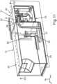
- FIG. 11 A perspective view of a sectional view of an embodiment of a water supply device 15 is shown. As can be seen in this illustration, a nozzle 64 of the water tank 25 is coupled to the nozzle 31 of the subassembly 21.
- a detection element 65 is arranged in the water tank 25.
- the detection element 65 can be a magnetic float.
- its movement is guided by a guide device 66.
- a linear movement in the vertical direction in particular is guided particularly advantageously.
- This movement can be limited by a stop element 67.
- the stop element 67 is arranged below a maximum possible fill level of water in the water tank 25 when viewed in the vertical direction. This means that the detection element 65 can only float up to this stop element 67.
- This detection element 65 is in particular part of a fill level detection device. This in turn is in particular part of the water supply device 15.
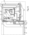
- Another component of this fill level detection device can be a sensor unit 68, as shown in Fig. 12 This sensor unit 68 is arranged in particular in the subassembly 21, in particular in the interior of the housing 22.
- the sensor unit 68 is installed in a fixed location therein.
- the sensor unit 68 can be a reed switch, for example. It is arranged in such a way, particularly when viewed in the height direction, that in conjunction with the detection element 65 it detects a water level in the water tank 25 that does not relate to the maximum level and not to the empty level and thus to the empty level of the water tank 25. Rather, an intermediate level in between can be directly detected as the level.
- the empty fill level of the water tank 25 can also be determined indirectly with just a single sensor unit 68. In one embodiment, this is done by detecting a detection element 65 arranged vertically on the water tank with this sensor unit 68. In particular, when the fill level increases accordingly, for example when filling, this detection element 65 floats up and thus moves vertically upwards. If it is moved so far upwards that the reed switch in the form of the sensor unit 68, which is preferably present here, is triggered, in particular closed, due to the magnetic field, this intermediate fill level is detected directly. There can then also be a higher fill level in the water tank 25, for example the water tank 25 can be filled to the maximum. In the present embodiment, this is not detected directly with the sensor unit 68. In particular, overflow is prevented because the water tank 25 is filled manually by a user.
- the fill level drops. If this fill level drops below this intermediate fill level, the detection element 65 moves downwards from its upper position on the stop element 67. In the course of this fill level reduction, the sensor unit 68 then detects that this detection range has been left. This means that at a specific lower fill level, which is not the empty fill level, the sensor unit 68 corresponding departure of the detection element 65 from the detection range of the sensor unit 68 is detected. In the exemplary embodiment, this means that the reed switch is opened again.
- a further operating time and/or a further delivery rate that is delivered from this time onwards is then detected, in particular by at least one pump of the water supply device 15. This can be done by corresponding sensors and/or a control unit.
- this further operating time and/or the further delivery rate is then compared with a predetermined reference operating time and/or a predetermined reference delivery rate.
- the reference operating time is a time period that describes how long it takes until the residual amount of water remaining in the water tank 25 has been pumped out, in particular sucked out by a pump, after the detection of the departure from the detection range.
- This reference operating time therefore characterizes the time period until the water in the water tank, starting from the fill level that was present when the detection element 65 detected that the sensor unit 68 had left the detection range, is completely empty in the water tank 25. The same can be done with a corresponding reference delivery rate. This then characterizes the delivery rate per unit of time that is required, in particular by at least one pump, to pump the water still present in the water tank 25 at the time at which the detection element 65 detected that the sensor unit had left the detection range, until the water has been completely pumped out of the water tank 25.
- this additional operating time corresponds to the reference operating time and/or the additional delivery quantity corresponds to the reference delivery quantity, the empty fill level and thus the empty water tank 25 can be determined indirectly and very precisely.
- the detection element 65 is one which is deliberately arranged to be immersed in the water, in particular only in certain areas.
- the sensor unit 68 is positioned in such a way that the detection area is left when the part of the detection element 65 immersed in the water is in a predetermined distance, for example about one millimeter, from the bottom 25a, in particular from the inside of the bottom 25a, of the water tank 25 or, in another embodiment, is arranged sitting straight on this bottom 25a.
- the fill level is determined when the water in the water tank 25 is reduced when at least one of the pumps 79, 80 is activated. If the switch is then opened, in particular because the detection element 65 moves out of the detection range of the sensor unit 68, the fill level is determined. If, however, opening of the switch is detected and the pumps 79, 80 are deactivated, it is also detected that the water tank 25 is being removed by a user. In this case, the fill level is not determined.
- Fig. 13 a perspective view of a partial section is shown which represents the carrier 53.
- the preferably one-piece carrier 53 which is made in particular from plastic, preferably as an injection-molded component, is a multifunctional carrier or a multi-component carrier.
- the sensor unit 68 is arranged on this carrier 53 so that it can be detachably removed without causing any damage.
- the carrier 53 preferably has a holding unit 70 which is designed to hold the sensor unit 68 and which is integrated into and thus formed in one piece with it.
- the holding unit 70 has, in one embodiment, a first receiving web 71 and a second receiving web 72. These preferably each have a receptacle. These receptacles are formed here as support beds 73 and 74.
- These support beds 73, 74 are formed here as ring sections. These freely projecting receiving webs 71 and 72 thus receive the sensor unit 68 in these support beds 73 and 74.
- the receiving webs 71, 72 can also be referred to as retaining brackets.
- the holding unit 70 also has at least one snap element 98.
- This is a freely projecting tongue. It is also attached to a Support wall 69 is formed in one piece.
- the support wall 69 is preferably formed on the base body 54, in particular designed to protrude therefrom.
- the snap element 98 is arranged separately from the receiving webs 71 and 72. With this snap element 74, a snap connection with the sensor unit 68 can be created. In particular, the snap element 74 snaps onto a housing of the sensor unit 68.
- Fig. 14 is a partial section with the components according to Fig. 13 and the sensor unit 68 is shown in the assembled final state.
- the housing of the sensor unit 68 engages in the receptacles of the receiving webs 71 and 72.
- a snap connection with this housing is formed via the snap element 98.
- the holding unit 70 has a stop wall 75.
- This stop wall 75 can be part of the support wall 69.
- the stop wall 75 is intended for the abutting positioning of a stop web 76 of the sensor unit 68. This is particularly the case when the sensor unit 68 is arranged in the mounted end position on the support 53.
- the support wall 69 is designed as an angled, in particular multi-angled, stiffening strip.
- the carrier 53 is designed as a one-piece component. In particular, it is realized as an injection-molded component.
- the carrier 53 has a holding arm 77. In particular, this holding arm 77 is arranged protruding from the base body 54. In particular, it is oriented in a freely cantilevered manner.
- the holding arm 77 is designed as intended to receive and thus also hold at least one hose 78 and/or at least one pump 79 and/or 80 of the water supply device 15.
- the holding arm 77 preferably has a receptacle 81. This can be a receptacle that is open at the top.
- the hose 78 can thus be inserted into this from above. It is then safely and reliably positioned and can be easily assembled and disassembled thanks to this design.
- the nozzle 31 is also shown here.
- the receptacle 81 has engagement webs 82. These are integrally formed onto the holder 81. They can engage in groove-like holders 83 of the hose coupling for the hose 78. This enables a particularly precise and stable mounting on the holding arm 77.
- the carrier 53 has a holding structure 84.
- this holding structure 84 is a separate unit of the carrier 53 from the holding arm 77.
- the holding structure 84 is designed to receive and hold at least one hose 78 and/or 85.
- the holding structure 84 is provided in addition to or instead of receiving or holding at least one pump 79 and/or 80.
- two pumps 79 and 80 are part of the water supply device 15. However, there can also be more or fewer such pumps.
- the carrier 53 is preferably designed to be able to carry at least one hose, in particular all hoses, and/or at least one pump, in particular all pumps, of the water supply device 15. In particular, these components are accommodated, in particular suspended, in corresponding receptacles.
- the carrier 53 is thus designed such that the hoses and/or the pumps are arranged suspended from the carrier 53.
- the pumps 79 and 80 can also be arranged freely hanging on this carrier 53. Only the hoses can then be inserted directly into corresponding receptacles from above and suspended therefrom, and the pumps 79 and 80 can be arranged freely hanging. They are then in particular only suspended from the carrier 53 via the hoses.
- nozzles of the pumps 79 and/or 80 to which the hoses 78 and 85 open, to protrude into corresponding receptacles and therefore the pumps themselves are also suspended or suspended from these components.
- the holding structure 84 has a water basin 86.
- the water basin 86 therefore represents an intermediate reservoir for water which is conveyed from the water tank 25 to an outlet of the water supply device 15.
- Such an outlet can be formed, for example, by an outlet 87 ( Fig.2 ) can be formed.
- this outlet 87 is arranged lower in height than the water tank 25, such a water basin 86 is Intermediate reservoir is particularly advantageous. This is due to the hydrostatic pressure that arises due to this height difference.
- This water basin 86 can thus compensate for this hydrostatic pressure, so that undesirable dripping of water from this outlet 87 can be avoided. In particular, this makes it possible for no more water to drip out of this outlet 87 after filling the device 17, in particular an ice mold tray. This makes it easy to avoid the ice tray overflowing.
- this water basin 86 is formed in one piece with this carrier 53. It is particularly integrated into this carrier 53. As in Fig. 15 As can also be seen, in one embodiment this water basin 86 can be arranged so as to protrude from the base body 54. In particular, this water basin 86 can be oriented so as to protrude freely from this base body 54.
- the water basin 86 is designed in one embodiment as a shaft-like structure. It is particularly advantageous if an upwardly open receptacle 89 is formed in a boundary wall 88 of the water basin 86. In this, a Fig. 15 An additional water hose (not shown) can be attached.
- the holding structure 84 has at least one holding claw 90.
- several such holding claws 90, 91, 92 and 93 are provided.
- These holding claws 90 to 93 extend freely from the holding structure 84, in particular the water basin 86, in particular the inner boundary wall 88. In particular, they extend in the direction of the holding arm 77, which is preferably present and separate from the holding structure 84.
- this carrier 53 provides a free space 94 between the holding structure 84 and the holding arm 77. Components of the water supply device 15, such as hoses and/or pumps, can be arranged in this free space 94 in a very compact and space-saving manner and can be held very stably.
- Fig. 16 the arrangement is in accordance with Fig. 15 shown in a top view, whereby the exemplary hoses 78, 85 and 95 are not shown here.
- the position and design of the holding claws 90 to 93 are shown. They each preferably have claw openings 90a, 91a, 92a and 93a. These are oriented upwards in the vertical direction and thus open at the top. This makes it particularly easy to Mounting of the additional components, such as hoses and pumps.
- these attached components can then be easily held by these holding claws 90 to 93. In particular, they can then be held stably in these claw openings 90a to 93a by the corresponding weight force.
- FIG. 17 An exploded view of an embodiment of the carrier 53 and a pre-assembly assembly or a pre-assembly module 96 is shown.
- the pre-assembly module 96 has, for example, the pumps 79 and 80 and at least some of the hoses 85, 78 and a further hose 97.
- This hose 97 is preferably the one that is then also shown in the assembled state in Fig. 18 which flows into the water basin 86. In particular, it is inserted in the holder 89.
- the individual components of the carrier 53 as already explained in detail above, can be seen here in more detail.
- Fig. 18 is the composite state of the Fig. 17 shown components.
Landscapes
- Engineering & Computer Science (AREA)
- Physics & Mathematics (AREA)
- Mechanical Engineering (AREA)
- Thermal Sciences (AREA)
- General Engineering & Computer Science (AREA)
- Chemical & Material Sciences (AREA)
- Combustion & Propulsion (AREA)
- Devices For Dispensing Beverages (AREA)
- Devices That Are Associated With Refrigeration Equipment (AREA)
Applications Claiming Priority (1)
| Application Number | Priority Date | Filing Date | Title |
|---|---|---|---|
| DE102022212213.5A DE102022212213A1 (de) | 2022-11-16 | 2022-11-16 | Wasserbereitstellungseinrichtung für eine Flüssigkeits- und/oder Eisausgabeeinheit eines Haushaltskältegeräts mit einem Träger mit spezifischem Haltearm, sowie Haushaltskältegerät |
Publications (2)
| Publication Number | Publication Date |
|---|---|
| EP4372159A1 true EP4372159A1 (fr) | 2024-05-22 |
| EP4372159B1 EP4372159B1 (fr) | 2026-03-25 |
Family
ID=88833968
Family Applications (1)
| Application Number | Title | Priority Date | Filing Date |
|---|---|---|---|
| EP23209579.4A Active EP4372159B1 (fr) | 2022-11-16 | 2023-11-14 | Dispositif d'alimentation en eau pour une unité de distribution de liquide et/ou de glace d'un appareil frigorifique ménager pourvu d'un support à bras de retenue spécifique, et appareil frigorifique ménager équipé d'un tel dispositif |
Country Status (2)
| Country | Link |
|---|---|
| EP (1) | EP4372159B1 (fr) |
| DE (1) | DE102022212213A1 (fr) |
Citations (4)
| Publication number | Priority date | Publication date | Assignee | Title |
|---|---|---|---|---|
| US20080168791A1 (en) * | 2005-03-15 | 2008-07-17 | Eltek S.P.A | Refridgerating Apparatus With a Liquid Supply System |
| US10794628B2 (en) * | 2017-01-03 | 2020-10-06 | Samsung Electronics Co., Ltd. | Refrigerator and method of controlling the same |
| US20210180853A1 (en) * | 2019-12-16 | 2021-06-17 | Lg Electronics Inc. | Refrigerator |
| US20220034581A1 (en) * | 2020-07-30 | 2022-02-03 | Lg Electronics Inc. | Refrigerator |
Family Cites Families (1)
| Publication number | Priority date | Publication date | Assignee | Title |
|---|---|---|---|---|
| KR100776295B1 (ko) * | 2006-09-06 | 2007-11-16 | 엘지전자 주식회사 | 냉장고 |
-
2022
- 2022-11-16 DE DE102022212213.5A patent/DE102022212213A1/de active Pending
-
2023
- 2023-11-14 EP EP23209579.4A patent/EP4372159B1/fr active Active
Patent Citations (4)
| Publication number | Priority date | Publication date | Assignee | Title |
|---|---|---|---|---|
| US20080168791A1 (en) * | 2005-03-15 | 2008-07-17 | Eltek S.P.A | Refridgerating Apparatus With a Liquid Supply System |
| US10794628B2 (en) * | 2017-01-03 | 2020-10-06 | Samsung Electronics Co., Ltd. | Refrigerator and method of controlling the same |
| US20210180853A1 (en) * | 2019-12-16 | 2021-06-17 | Lg Electronics Inc. | Refrigerator |
| US20220034581A1 (en) * | 2020-07-30 | 2022-02-03 | Lg Electronics Inc. | Refrigerator |
Also Published As
| Publication number | Publication date |
|---|---|
| EP4372159B1 (fr) | 2026-03-25 |
| DE102022212213A1 (de) | 2024-05-16 |
Similar Documents
| Publication | Publication Date | Title |
|---|---|---|
| DE102006063049B3 (de) | Kühlschranktür | |
| DE102008016631B4 (de) | Kabelhalter, Haushaltsgerät und Verfahren zur Verlegung von Kabeln in einem Haushaltsgerät | |
| DE3510890A1 (de) | Kraftstoffoerdersystem | |
| DE102014008876A1 (de) | Kühl- und/oder Gefriergerät | |
| EP4372159A1 (fr) | Dispositif d'alimentation en eau pour une unité de distribution de liquide et/ou de glace d'un appareil frigorifique ménager pourvu d'un support à bras de retenue spécifique, et appareil frigorifique ménager équipé d'un tel dispositif | |
| EP4372158A1 (fr) | Dispositif d'alimentation en eau pour une unité de distribution de liquide et/ou de glace d'un appareil frigorifique ménager doté d'un support spécifique avec une structure de retenue, et appareil frigorifique ménager équipé d'un tel dispositif | |
| EP4372157A1 (fr) | Dispositif d'alimentation en eau pour une unité de distribution de liquide et/ou de glace d'un appareil frigorifique ménager, et appareil frigorifique ménager équipé de ce dispositif d'alimentation en eau, et procédé de montage d'un tel dispositif de distribution d'eau | |
| EP4372161A1 (fr) | Dispositif d'alimentation en eau pour une unité de distribution de liquide et/ou de glace d'un appareil frigorifique ménager | |
| DE102022212214A1 (de) | Haushaltskältegerät mit spezifischem Einlegeteil zum frei tragenden Anhängen einer Komponente einer Wasserbereitstellungseinrichtung, sowie Verfahren | |
| EP4372160A1 (fr) | Appareil frigorifique ménager doté d'un insert spécifique doté d'un raccord s'étendant dans la zone de mousse | |
| DE102022213769A1 (de) | Haushaltskältegerät mit spezifischem Einlegeteil mit in den Schaumbereich ragenden Koppelstutzen | |
| DE102022212218A1 (de) | Haushaltskältegerät mit spezifischem Einlegeteil mit in den Schaumbereich ragenden Koppelstutzen | |
| WO2008028753A2 (fr) | Appareil réfrigérant | |
| EP2397698B1 (fr) | Dispositif d'acheminement | |
| EP1672294A2 (fr) | Système de conditionnement d'air | |
| WO2005090882A1 (fr) | Appareil frigorifique integre avec unite de socle | |
| EP0190793A1 (fr) | Réfrigérateur | |
| DE102015218449A1 (de) | Verfahren zum Herstellen eines Haushaltskältegeräts mit spezifisch befestigter Rückwand sowie Haushaltskältegerät | |
| EP4696958A1 (fr) | Appareil frigorifique ménager doté d'un préparateur de glace réversible | |
| DE102016218636A1 (de) | Abdeckplatte für ein Haushaltsgerät sowie Haushaltsgerät und Verfahren zur Montage einer Abdeckplatte | |
| DE102008054995A1 (de) | Kältegerät mit Luftfilter | |
| EP2005078A2 (fr) | Appareil frigorifique encastrable | |
| DE102008042908A1 (de) | Kältegerät mit Kaltluftkanal | |
| DE29501289U1 (de) | Kühlgerät | |
| DE102022209572A1 (de) | Haushaltskältegerät mit geneigter Komponenten-Führungsbahn und darin integriertem Auszugsstopp |
Legal Events
| Date | Code | Title | Description |
|---|---|---|---|
| PUAI | Public reference made under article 153(3) epc to a published international application that has entered the european phase |
Free format text: ORIGINAL CODE: 0009012 |
|
| STAA | Information on the status of an ep patent application or granted ep patent |
Free format text: STATUS: THE APPLICATION HAS BEEN PUBLISHED |
|
| AK | Designated contracting states |
Kind code of ref document: A1 Designated state(s): AL AT BE BG CH CY CZ DE DK EE ES FI FR GB GR HR HU IE IS IT LI LT LU LV MC ME MK MT NL NO PL PT RO RS SE SI SK SM TR |
|
| STAA | Information on the status of an ep patent application or granted ep patent |
Free format text: STATUS: REQUEST FOR EXAMINATION WAS MADE |
|
| 17P | Request for examination filed |
Effective date: 20241122 |
|
| RBV | Designated contracting states (corrected) |
Designated state(s): AL AT BE BG CH CY CZ DE DK EE ES FI FR GB GR HR HU IE IS IT LI LT LU LV MC ME MK MT NL NO PL PT RO RS SE SI SK SM TR |
|
| REG | Reference to a national code |
Ref country code: DE Ref legal event code: R079 Free format text: PREVIOUS MAIN CLASS: E03C0001020000 Ipc: F25C0005200000 Ref document number: 502023003500 Country of ref document: DE |
|
| GRAP | Despatch of communication of intention to grant a patent |
Free format text: ORIGINAL CODE: EPIDOSNIGR1 |
|
| STAA | Information on the status of an ep patent application or granted ep patent |
Free format text: STATUS: GRANT OF PATENT IS INTENDED |
|
| RIC1 | Information provided on ipc code assigned before grant |
Ipc: F25C 5/20 20180101AFI20251027BHEP Ipc: F25D 23/12 20060101ALI20251027BHEP |
|
| INTG | Intention to grant announced |
Effective date: 20251112 |
|
| GRAS | Grant fee paid |
Free format text: ORIGINAL CODE: EPIDOSNIGR3 |
|
| GRAA | (expected) grant |
Free format text: ORIGINAL CODE: 0009210 |
|
| STAA | Information on the status of an ep patent application or granted ep patent |
Free format text: STATUS: THE PATENT HAS BEEN GRANTED |
|
| AK | Designated contracting states |
Kind code of ref document: B1 Designated state(s): AL AT BE BG CH CY CZ DE DK EE ES FI FR GB GR HR HU IE IS IT LI LT LU LV MC ME MK MT NL NO PL PT RO RS SE SI SK SM TR |
|
| REG | Reference to a national code |
Ref country code: CH Ref legal event code: F10 Free format text: ST27 STATUS EVENT CODE: U-0-0-F10-F00 (AS PROVIDED BY THE NATIONAL OFFICE) Effective date: 20260325 Ref country code: GB Ref legal event code: FG4D Free format text: NOT ENGLISH |
|
| REG | Reference to a national code |
Ref country code: DE Ref legal event code: R096 Ref document number: 502023003500 Country of ref document: DE |
|
| REG | Reference to a national code |
Ref country code: IE Ref legal event code: FG4D Free format text: LANGUAGE OF EP DOCUMENT: GERMAN |