EP4372192A1 - Ensemble poignée de véhicule automobile - Google Patents
Ensemble poignée de véhicule automobile Download PDFInfo
- Publication number
- EP4372192A1 EP4372192A1 EP23190002.8A EP23190002A EP4372192A1 EP 4372192 A1 EP4372192 A1 EP 4372192A1 EP 23190002 A EP23190002 A EP 23190002A EP 4372192 A1 EP4372192 A1 EP 4372192A1
- Authority
- EP
- European Patent Office
- Prior art keywords
- lever
- door handle
- movement
- drive
- handle
- Prior art date
- Legal status (The legal status is an assumption and is not a legal conclusion. Google has not performed a legal analysis and makes no representation as to the accuracy of the status listed.)
- Pending
Links
Images


Classifications
-
- E—FIXED CONSTRUCTIONS
- E05—LOCKS; KEYS; WINDOW OR DOOR FITTINGS; SAFES
- E05B—LOCKS; ACCESSORIES THEREFOR; HANDCUFFS
- E05B85/00—Details of vehicle locks not provided for in groups E05B77/00 - E05B83/00
- E05B85/10—Handles
- E05B85/107—Pop-out handles, e.g. sliding outwardly before rotation
-
- E—FIXED CONSTRUCTIONS
- E05—LOCKS; KEYS; WINDOW OR DOOR FITTINGS; SAFES
- E05B—LOCKS; ACCESSORIES THEREFOR; HANDCUFFS
- E05B77/00—Vehicle locks characterised by special functions or purposes
- E05B77/02—Vehicle locks characterised by special functions or purposes for accident situations
- E05B77/04—Preventing unwanted lock actuation, e.g. unlatching, at the moment of collision
- E05B77/06—Preventing unwanted lock actuation, e.g. unlatching, at the moment of collision by means of inertial forces
-
- E—FIXED CONSTRUCTIONS
- E05—LOCKS; KEYS; WINDOW OR DOOR FITTINGS; SAFES
- E05B—LOCKS; ACCESSORIES THEREFOR; HANDCUFFS
- E05B81/00—Power-actuated vehicle locks
- E05B81/24—Power-actuated vehicle locks characterised by constructional features of the actuator or the power transmission
- E05B81/32—Details of the actuator transmission
- E05B81/42—Cams
-
- E—FIXED CONSTRUCTIONS
- E05—LOCKS; KEYS; WINDOW OR DOOR FITTINGS; SAFES
- E05B—LOCKS; ACCESSORIES THEREFOR; HANDCUFFS
- E05B81/00—Power-actuated vehicle locks
- E05B81/54—Electrical circuits
- E05B81/90—Manual override in case of power failure
-
- E—FIXED CONSTRUCTIONS
- E05—LOCKS; KEYS; WINDOW OR DOOR FITTINGS; SAFES
- E05B—LOCKS; ACCESSORIES THEREFOR; HANDCUFFS
- E05B85/00—Details of vehicle locks not provided for in groups E05B77/00 - E05B83/00
- E05B85/10—Handles
- E05B85/103—Handles creating a completely closed wing surface
Definitions
- the invention relates to a handle arrangement of a motor vehicle, wherein the handle arrangement comprises a carrier element which can be fastened to a vehicle door of the motor vehicle, a drive element which is movably mounted on the carrier element, a drive lever which is mounted on the carrier element so as to be rotatable about a drive axis and which is designed to be movable from a rest position into an operating position with the aid of the drive element, a door handle which is designed to be movable with the aid of the drive element between a retracted position in which the door handle is arranged to run flush with the outside of the vehicle door and an extended position in which the door handle is arranged to be extended in an opening direction relative to the outside of the vehicle door for manual operation, with a first longitudinal end which is connected to the drive lever and a second longitudinal end, and a movement lever which is mounted on the carrier element so as to be rotatable about a movement axis and which is connected to the second longitudinal end of the door handle.
- Such handle arrangements with a door handle that is flush or flush with the surface in a retracted position and that is arranged parallel to the outside in an extended position are known from the prior art.
- Such known handle arrangements have a wide variety of safety systems to prevent the door handle from being extended inadvertently and the door handle from being operated inadvertently to open the vehicle door.
- These safety systems are referred to as crash locks and have, for example, a mass balancing element to compensate for an acceleration force acting on the door handle in the event of a vehicle accident. to counteract this and to hold the door handle in a position in which the vehicle door cannot be opened.
- Such mass balancing elements are attached, for example, to a lever which is used to extend the door handle, with such mass balancing elements being moved permanently with the lever connected to the door handle, even during normal operation of the handle arrangement.
- the mass balancing elements are designed with a specific mass balancing weight and a specific lever length to suit the desired effectiveness.
- the lever length in particular has a detrimental effect on the installation space depth in the case of a lever which is permanently connected to the door handle, so that a correspondingly large installation space depth must be provided for the movement of the mass balancing element which is also moved.
- a larger installation space depth runs counter to today's modern design requirements for a small installation depth.
- the object of the invention is therefore to provide a handle arrangement of a motor vehicle in which the above-mentioned disadvantage is avoided and which is nevertheless characterized by a high level of safety in the event of a vehicle accident.
- the drive element has an extension control disk with an extension cam contour, wherein the extension cam contour is designed to move the drive lever from the rest position to the operating position during operation of the drive element.
- the invention provides that the door handle is arranged in the extended position when the drive lever is arranged in its operating position. This arrangement of door handle and drive lever applies to normal operation of the handle arrangement.
- the invention provides in a further embodiment that the drive lever and the movement lever are connected to one another in a movement-coupled manner via a coupling rod. Consequently, it is sufficient if the drive lever is driven and the drive force of the drive element acting on the drive lever is transmitted to the movement lever via the coupling rod.
- the mass balancing element is mounted on the support element so that it can rotate about an axis of rotation which is arranged between the drive axis and the movement axis, and is designed with a first lever arm and a second lever arm.
- the separate mounting of the mass balancing element makes it possible to decouple the movement of the mass balancing element from the components for moving the door handle into the extended position.
- a mass weight is arranged on the first lever arm and the second lever arm is designed with a coupling element which can be brought into engagement with the movement lever for a movement coupling.
- the door handle can be moved from its extended position when manually operated by a user into an actuating position in which the door handle is arranged with its second longitudinal end extended further in the extension direction than the first longitudinal end and pivoted about the axis of movement.
- the invention provides in one embodiment that the first longitudinal end of the door handle is provided with a locking lever with the drive lever.
- the locking lever When the locking lever is disengaged from the drive lever, the door handle can be moved to a position in which a user can grasp and manipulate the door handle to open the vehicle door mechanically.
- the invention provides in a further embodiment that the unlocking device has a guide recess formed at the first longitudinal end, a pivot pin formed on the drive lever, with which the drive lever and the first longitudinal end are articulated to one another and which is movable against the force of a mechanical return element within the guide recess, and an unlocking projection formed at the first longitudinal end of the door handle.
- the first longitudinal end of the door handle is movable against the opening direction and is designed to force the locking lever out of engagement with the drive lever with the aid of the unlocking projection.
- a motor vehicle 1 in the form of a passenger car is shown as an example, which in the example has four vehicle doors 2 (two of which are made of Figure 1 visible) which can be opened via a respective handle arrangement 3 and in particular with the aid of a door handle 4 of the handle arrangement 3.
- the vehicle doors 2 are firmly locked via a respective door lock and can be opened from the outside via a respective movement of the door handle 4.
- the handle arrangement can be used not only for vehicle doors 2, but also for any type of flap of motor vehicles 1.
- FIGS 2 to 5 show in perspective view one of the vehicle doors 2 and the door handle 4 used to open the vehicle door 2, wherein the door handle 4 in the Figure 2 in a retracted position in which Figure 3 in an extended position, in Figure 4 in an operating position and in Figure 5 shown arranged in an emergency opening position.
- the door handle 4 in its retracted position is approximately flush with an outer side 5 of the vehicle door 2, ie flush or flush with the surface, In this position, the door handle 4 is in its retracted position in which it is not used.
- the door handle 4 is in a Figure 3 shown extended position, in which the door handle 4 protrudes from the outside 5 of the vehicle door 2 and is arranged in an extended position compared to the retracted position. Accordingly, the door handle 4 is arranged in a protruding position from the vehicle door 2 in that the door handle 4 was previously moved in an extended direction 7.
- the door handle 4 In the extended position, the door handle 4 is arranged in the extension direction 7 for manual operation by a user relative to the outside 5 of the vehicle door 2, so that a user can then reach behind the door handle 4 and operate or handle it to open the vehicle door 2.
- the force applied by the user to the door handle 4 causes the door handle to be moved further in the extension direction 7 at one of its longitudinal ends in order to open the vehicle door 2. If the door handle reaches an operating position which is in Figure 4 shown, opens the vehicle door 2.
- the door handle 4 can be pushed inwards by a user at one longitudinal end against the opening direction 7 into a Figure 5 shown pressing direction 8, whereby the other longitudinal end of the door handle 4 is moved in the opening direction 7, so that a user can grasp behind the longitudinal end of the door handle 4 moved in the opening direction 7 in order to pull the door handle 4 out further and operate it manually.
- the Figure 6 shows a perspective rear view of the handle assembly 3, which has a carrier element 6, which can be fastened to the vehicle door 2.
- the handle arrangement 3 has a drive element 9 movably mounted on the carrier element 6, a drive lever 10 mounted on the carrier element 6, a locking lever 11 mounted on the carrier element 6, a movement lever 12 mounted on the carrier element 6 and a mass balancing element 14.
- the drive element 10 is motor-driven in rotation by an actuator 15 mounted on the carrier element 6.
- the drive lever 10 is rotatably mounted on the carrier element 6 about a drive axis 16, wherein the drive lever 10 is designed to be movable from a rest position into an operating position with the aid of the drive element 9.
- the movement lever 12 is rotatably mounted on the carrier element 6 about a movement axis 17.
- the mass balancing element 14 is also movably mounted on the carrier element 6, wherein the mass balancing element 14 generates a counterforce in the event of a crash of the motor vehicle 1 with the door handle 4 extended, which counteracts an acceleration force acting on the extended door handle 4 and holds the door handle 4 in its extended position in order to prevent an unwanted opening of the vehicle door 2.
- the handle arrangement 3 also has a coupling rod 18, wherein the drive lever 10 and the movement lever 12 are connected to one another in a movement-coupled manner via the coupling rod 18.
- the handle arrangement 3 shown further comprises a locking cylinder 19 and a Bowden cable lever 20 for a purely mechanical unlocking and opening of the vehicle door 2, wherein the locking cylinder 19 and the Bowden cable lever 20, which is coupled to a locking device in a known manner via a Bowden cable, represent purely optional components.
- FIGs 7 and 8 show again the handle arrangement 3 according to the invention in perspective views, wherein in Figure 7 the door handle 4 is shown separately from the actual handle arrangement 3.
- the door handle 4 has a first longitudinal end 21 and a second longitudinal end 22.
- the first longitudinal end 21 of the door handle 4 is connected to the drive lever 10, whereas the second longitudinal end 22 of the door handle 4 is connected to the movement lever 12.
- Coupling parts 23a and 23b are shown at the respective connecting ends of the drive lever 10 and the movement lever 12, wherein in the assembled state the coupling parts 23a, 23b are fastened within the hollow door handle 4.
- the drive element 9 consequently ensures a movement of both the drive lever 10 and the locking lever 11.
- the drive element 9 has a release control disc 24 with a release cam contour 25, as can be seen, for example, from the Figures 9 and 10
- the release cam contour 25 is designed in such a way that when the drive element 9 moves or when the drive element 9 is in operation, the locking lever 11 is disengaged from the Drive lever 10 is moved.
- the drive element 9 also has an extension control disk 26 with an extension cam contour 27. When the drive element 9 moves or when the drive element 9 is in operation, the extension cam contour 27 moves the drive lever 10 from the rest position to the operating position.
- the release control disk 24 and the extension control disk 26 are arranged and designed one above the other on the drive element 9.
- the mass balancing element 14 serves, when the door handle 4 is arranged in its extended position, to counteract an acceleration force acting on the door handle 4 in the event of a crash.
- the mass balancing element 14 is rotatably mounted on the carrier element via a rotation axis 28.
- the rotation axis 28 is arranged between the drive axis 16 and the movement axis 17. According to the invention, the mass balancing element 14 is pivotable when the door handle 4 is moved from the retracted position in the direction of the extension direction 7 of the movement lever 12.
- the mass balancing element 14 is then coupled to the movement lever 12 and is designed to move with the movement of the movement lever 12.
- the mass balancing element 14 is designed with a first lever arm 29 and a second lever arm 30.
- a mass weight 31 is arranged on the first lever arm 29, whereas the second lever arm 30 is designed with a coupling element 32 which can be brought into engagement with the movement lever 12 for a movement coupling.
- the movement lever 12 has a recess 33 into which the hook-shaped coupling element 32 can engage.
- FIGS. 1 and 2 wherein for reasons of clarity the carrier element 6 is not shown therein.
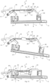
- the Figure 12 shows a basic position of the handle arrangement 3, in which the drive element 9 is not in operation, the locking lever 11 is arranged in its locking position, the door handle 4 is arranged in its retracted position and accordingly the drive lever 10 is arranged in its rest position.
- the locking lever 11 has a recess 34 in which a retaining pin 35 of the drive lever 10 is arranged, so that the locking lever 11 blocks a movement of the drive lever 10 in the opening direction 7 and the door handle 4 is held in its retracted position.
- the hook-shaped coupling element 32 is located within the recess 33 of the movement lever 12 and rests there on a neutral radius of the recess 33.
- the drive element 9 is activated and begins to rotate until the Figure 13 shown position is reached, in which the door handle 4 is arranged in its extended position, whereby the locking lever 11 was previously pushed into its released position by the release disk 24 of the drive element 9 and then the extension control disk 25 has moved the drive lever 10 into its operating position.
- the door handle 4 is arranged in the extended position when the drive lever 10 is arranged in its operating position.
- the mass balancing element 14 is still arranged immobile and has the position that it assumed in the retracted position of the door handle 4.
- the movement lever 12 now assumes a different position to the mass balancing element 14, as the Figure 13 can be seen.
- the hook-shaped coupling element 32 moves along the neutral radius 36 of the recess 33.
- the hook-shaped coupling element 32 rests against a stop edge 37 of the recess 33, so that the mass balancing element 14 is now motion-coupled to the movement lever 12 when the extended position of the door handle 4 is reached.
- the Figure 14 shows the handle assembly 3 in a position in which the door handle 4 has been operated and pulled by a user.
- the Door handle 4 is now in its operating position, in which the vehicle door 2 is opened.
- the mass balancing element is coupled to the movement lever 12 when the door handle 4 is moved beyond the extended position and is moved along with the movement of the movement lever 12, because the mass balancing element 14 is arranged pivoted about the axis of rotation 28, which is due to the movement of the second longitudinal end 22 of the door handle 4 and the further pivoted movement lever 12.
- the door handle 4 In the actuation position of the door handle 4 shown, the door handle 4 is arranged with its second longitudinal end 22 further in the extension direction 7 than the first longitudinal end 21.
- the first longitudinal end 21 of the door handle 4 remains in the position in which the first longitudinal end 21 is arranged in the extended position of the door handle 4.
- the door handle 4 is arranged pivoted about the movement axis 17. This further pivoting movement of the movement lever 12 is realized by an elongated hole 38 at the longitudinal end of the movement lever 12, which is connected to the second longitudinal end 22 of the door handle 4.
- the above description was based on normal operation of the handle assembly 3, in which the door handle 4 is extended via the motor-driven drive element 9 so that a user can operate the door handle 4 to open the vehicle door 2.
- the Figure 15 now shows a power-free emergency operation, in which the drive element 9 is out of operation and the door handle 4 cannot extend.
- the user has the option of manually moving the door handle 4 out of its retracted position. To do this, the user must exert a pressure force on the first longitudinal end 21 of the door handle 4, whereby the first longitudinal end of the door handle 4 is moved in the pressing direction 8.
- the door handle 4 pivots about the movement axis 17 of the movement lever 12, so that the second longitudinal end 22 of the door handle 4 is arranged in an extended position, as shown in Figure 15 is shown.
- the first longitudinal end 21 of the door handle 4 When the first longitudinal end 21 of the door handle 4 is pressed in, the locking lever 11 moves from its locking position into a position in which the locking lever 11 releases the drive lever 10. This release is necessary because the bearing of the door handle 4 is a coupled system and actuation and emergency actuation of the door handle 4 is only possible with a release of the drive lever 10.
- the first longitudinal end 21 of the door handle 4 is designed with an unlocking device 40 that disengages the locking lever 11 from the drive lever 10.
- the unlocking device 40 has a guide recess 41 formed on the first longitudinal end 21 of the door handle 4, a pivot pin 42 formed on the drive lever 10 and an unlocking projection 43 formed on the first longitudinal end 21 of the door handle 4 (see for example Figures 7 and 15 ).
- the drive lever 10 and the first longitudinal end 21 of the door handle 4 are connected to one another in an articulated manner, whereby the pivot pin 42 is counteracted by the force of a mechanical return element, which can be designed as a spring element, is relatively movable within the guide recess 41.
- a mechanical return element which can be designed as a spring element
- the first longitudinal end 21 of the door handle 4 can be moved in the pressing direction 8 without the drive lever 10 moving.
- the first longitudinal end 21 of the door handle 4 is consequently movable against the opening direction 7 and, with the aid of the unlocking projection 43, is designed to force the locking lever 11 out of engagement with the drive lever 10.
- the unlocking projection 43 is designed as a section of the housing of the door handle 4, although other designs are also conceivable. With the aid of this manual unlocking by a user, the door handle 4 can then be moved into a position as shown in Figure 13 is shown, so that an operation of the door handle 4 according to Figure 14 can be executed.
Landscapes
- Lock And Its Accessories (AREA)
Applications Claiming Priority (1)
| Application Number | Priority Date | Filing Date | Title |
|---|---|---|---|
| DE102022130601.1A DE102022130601A1 (de) | 2022-11-18 | 2022-11-18 | Griffanordnung eines Kraftfahrzeugs |
Publications (1)
| Publication Number | Publication Date |
|---|---|
| EP4372192A1 true EP4372192A1 (fr) | 2024-05-22 |
Family
ID=87557983
Family Applications (1)
| Application Number | Title | Priority Date | Filing Date |
|---|---|---|---|
| EP23190002.8A Pending EP4372192A1 (fr) | 2022-11-18 | 2023-08-07 | Ensemble poignée de véhicule automobile |
Country Status (2)
| Country | Link |
|---|---|
| EP (1) | EP4372192A1 (fr) |
| DE (1) | DE102022130601A1 (fr) |
Cited By (1)
| Publication number | Priority date | Publication date | Assignee | Title |
|---|---|---|---|---|
| US20240271472A1 (en) * | 2023-02-13 | 2024-08-15 | Illinois Tool Works Inc. | Door Handle Assembly |
Families Citing this family (1)
| Publication number | Priority date | Publication date | Assignee | Title |
|---|---|---|---|---|
| DE102024121576A1 (de) * | 2024-07-30 | 2026-02-05 | Bayerische Motoren Werke Aktiengesellschaft | Aktuatorvorrichtung für ein Kraftfahrzeug, Flügelelement, Kraftfahrzeug sowie Verfahren |
Citations (3)
| Publication number | Priority date | Publication date | Assignee | Title |
|---|---|---|---|---|
| US20160281397A1 (en) * | 2015-03-24 | 2016-09-29 | Hyundai Motor Company | Retractable handle system for vehicle |
| EP3396088A1 (fr) * | 2017-04-27 | 2018-10-31 | Huf Hülsbeck & Fürst GmbH & Co. KG | Poignée de porte pour véhicule |
| CN114482730A (zh) * | 2021-12-02 | 2022-05-13 | 重庆霍富汽车部件有限公司 | 一种隐藏式汽车电动门把手 |
-
2022
- 2022-11-18 DE DE102022130601.1A patent/DE102022130601A1/de active Pending
-
2023
- 2023-08-07 EP EP23190002.8A patent/EP4372192A1/fr active Pending
Patent Citations (3)
| Publication number | Priority date | Publication date | Assignee | Title |
|---|---|---|---|---|
| US20160281397A1 (en) * | 2015-03-24 | 2016-09-29 | Hyundai Motor Company | Retractable handle system for vehicle |
| EP3396088A1 (fr) * | 2017-04-27 | 2018-10-31 | Huf Hülsbeck & Fürst GmbH & Co. KG | Poignée de porte pour véhicule |
| CN114482730A (zh) * | 2021-12-02 | 2022-05-13 | 重庆霍富汽车部件有限公司 | 一种隐藏式汽车电动门把手 |
Cited By (1)
| Publication number | Priority date | Publication date | Assignee | Title |
|---|---|---|---|---|
| US20240271472A1 (en) * | 2023-02-13 | 2024-08-15 | Illinois Tool Works Inc. | Door Handle Assembly |
Also Published As
| Publication number | Publication date |
|---|---|
| DE102022130601A1 (de) | 2024-05-23 |
Similar Documents
| Publication | Publication Date | Title |
|---|---|---|
| DE102017101418B4 (de) | Türgriffanordnung für eine Fahrzeugtür | |
| EP3688258B1 (fr) | Dispositif de poignée de porte de véhicule | |
| EP3728770B1 (fr) | Dispositif de poignée de porte d'un véhicule automobile | |
| EP3397829B1 (fr) | Ensemble poignée de porte d'un véhicule automobile | |
| EP4372192A1 (fr) | Ensemble poignée de véhicule automobile | |
| EP3803005A1 (fr) | Ensemble poignée de porte conçu pour un véhicule automobile | |
| EP3803006B1 (fr) | Ensemble poignée de porte conçu pour un véhicule automobile | |
| EP3277899B1 (fr) | Système de poignée de porte d'un véhicule automobile | |
| EP3857009B1 (fr) | Arrangement de poignée pour un véhicule automobile | |
| DE19916191B4 (de) | Vorrichtung zur Verriegelung einer Haube eines Kraftfahrzeuges | |
| DE10301998B4 (de) | Schließhilfe zum Verschließen einer mit einem Türschloß versehenen Fahrzeugtür | |
| EP3913181B1 (fr) | Élément de blocage de portière pourvu d'un support amovible | |
| DE202016102209U1 (de) | Crashsicherung für eine Kraftfahrzeugtür | |
| DE102020112935A1 (de) | Kraftfahrzeug-Türgriffanordnung | |
| WO2007118505A1 (fr) | SYSTèME DE DéPLACEMENT D'UN SIèGE DE VéHICULE | |
| EP3748109A1 (fr) | Dispositif de verrouillage | |
| DE102019125947B4 (de) | Notbetätigungsvorrichtung zum manuellen öffnen einer fahrzeugtür | |
| WO2024240365A1 (fr) | Ensemble poignée de véhicule automobile | |
| WO2024240366A1 (fr) | Ensemble poignée de véhicule automobile | |
| DE102023113429A1 (de) | Kraftfahrzeug-Bewegungssicherungs-Mechanismus | |
| DE102022130600A1 (de) | Griffanordnung eines Kraftfahrzeugs | |
| WO2021115592A1 (fr) | Dispositif de poignée de portière de véhicule automobile | |
| DE102023104395B4 (de) | Verriegelungsvorrichtung für einen gegenüber einem Gehäuseteil, insbesondere von Kraftfahrzeugen, zwischen einer Offen- und Schließstellung betätigbaren Deckel sowie Verfahren zum Ver- und Entriegeln eines einen Gehäuseteil verschließenden Deckels | |
| DE102023125173A1 (de) | Kraftfahrzeugschloss für ein Verschlusselement eines Kraftfahrzeugs | |
| DE102024110267A1 (de) | Verstellanordnung zum Verstellen eines Verschlusselements eines Kraftfahrzeugs |
Legal Events
| Date | Code | Title | Description |
|---|---|---|---|
| PUAI | Public reference made under article 153(3) epc to a published international application that has entered the european phase |
Free format text: ORIGINAL CODE: 0009012 |
|
| STAA | Information on the status of an ep patent application or granted ep patent |
Free format text: STATUS: THE APPLICATION HAS BEEN PUBLISHED |
|
| AK | Designated contracting states |
Kind code of ref document: A1 Designated state(s): AL AT BE BG CH CY CZ DE DK EE ES FI FR GB GR HR HU IE IS IT LI LT LU LV MC ME MK MT NL NO PL PT RO RS SE SI SK SM TR |
|
| STAA | Information on the status of an ep patent application or granted ep patent |
Free format text: STATUS: REQUEST FOR EXAMINATION WAS MADE |
|
| 17P | Request for examination filed |
Effective date: 20241122 |
|
| RBV | Designated contracting states (corrected) |
Designated state(s): AL AT BE BG CH CY CZ DE DK EE ES FI FR GB GR HR HU IE IS IT LI LT LU LV MC ME MK MT NL NO PL PT RO RS SE SI SK SM TR |