EP4372208A1 - Dichtung für gasturbinenmotor - Google Patents
Dichtung für gasturbinenmotor Download PDFInfo
- Publication number
- EP4372208A1 EP4372208A1 EP23208566.2A EP23208566A EP4372208A1 EP 4372208 A1 EP4372208 A1 EP 4372208A1 EP 23208566 A EP23208566 A EP 23208566A EP 4372208 A1 EP4372208 A1 EP 4372208A1
- Authority
- EP
- European Patent Office
- Prior art keywords
- seal
- carrier
- seal carrier
- axially
- aft
- Prior art date
- Legal status (The legal status is an assumption and is not a legal conclusion. Google has not performed a legal analysis and makes no representation as to the accuracy of the status listed.)
- Pending
Links
- 238000000034 method Methods 0.000 claims description 6
- 230000033001 locomotion Effects 0.000 description 7
- 239000000446 fuel Substances 0.000 description 4
- 239000000463 material Substances 0.000 description 4
- 230000003068 static effect Effects 0.000 description 3
- 230000009467 reduction Effects 0.000 description 2
- 230000008859 change Effects 0.000 description 1
- 238000004891 communication Methods 0.000 description 1
- 230000006835 compression Effects 0.000 description 1
- 238000007906 compression Methods 0.000 description 1
- 238000012937 correction Methods 0.000 description 1
- 238000002955 isolation Methods 0.000 description 1
- 238000005259 measurement Methods 0.000 description 1
- 230000007246 mechanism Effects 0.000 description 1
- 238000012986 modification Methods 0.000 description 1
- 230000004048 modification Effects 0.000 description 1
- 230000004044 response Effects 0.000 description 1
- 238000007789 sealing Methods 0.000 description 1
- 238000000926 separation method Methods 0.000 description 1
Images


Classifications
-
- F—MECHANICAL ENGINEERING; LIGHTING; HEATING; WEAPONS; BLASTING
- F01—MACHINES OR ENGINES IN GENERAL; ENGINE PLANTS IN GENERAL; STEAM ENGINES
- F01D—NON-POSITIVE DISPLACEMENT MACHINES OR ENGINES, e.g. STEAM TURBINES
- F01D11/00—Preventing or minimising internal leakage of working-fluid, e.g. between stages
- F01D11/001—Preventing or minimising internal leakage of working-fluid, e.g. between stages for sealing space between stator blade and rotor
-
- F—MECHANICAL ENGINEERING; LIGHTING; HEATING; WEAPONS; BLASTING
- F01—MACHINES OR ENGINES IN GENERAL; ENGINE PLANTS IN GENERAL; STEAM ENGINES
- F01D—NON-POSITIVE DISPLACEMENT MACHINES OR ENGINES, e.g. STEAM TURBINES
- F01D11/00—Preventing or minimising internal leakage of working-fluid, e.g. between stages
- F01D11/003—Preventing or minimising internal leakage of working-fluid, e.g. between stages by packing rings; Mechanical seals
-
- F—MECHANICAL ENGINEERING; LIGHTING; HEATING; WEAPONS; BLASTING
- F01—MACHINES OR ENGINES IN GENERAL; ENGINE PLANTS IN GENERAL; STEAM ENGINES
- F01D—NON-POSITIVE DISPLACEMENT MACHINES OR ENGINES, e.g. STEAM TURBINES
- F01D11/00—Preventing or minimising internal leakage of working-fluid, e.g. between stages
- F01D11/08—Preventing or minimising internal leakage of working-fluid, e.g. between stages for sealing space between rotor blade tips and stator
- F01D11/14—Adjusting or regulating tip-clearance, i.e. distance between rotor-blade tips and stator casing
- F01D11/16—Adjusting or regulating tip-clearance, i.e. distance between rotor-blade tips and stator casing by self-adjusting means
- F01D11/18—Adjusting or regulating tip-clearance, i.e. distance between rotor-blade tips and stator casing by self-adjusting means using stator or rotor components with predetermined thermal response, e.g. selective insulation, thermal inertia, differential expansion
-
- F—MECHANICAL ENGINEERING; LIGHTING; HEATING; WEAPONS; BLASTING
- F05—INDEXING SCHEMES RELATING TO ENGINES OR PUMPS IN VARIOUS SUBCLASSES OF CLASSES F01-F04
- F05D—INDEXING SCHEME FOR ASPECTS RELATING TO NON-POSITIVE-DISPLACEMENT MACHINES OR ENGINES, GAS-TURBINES OR JET-PROPULSION PLANTS
- F05D2240/00—Components
- F05D2240/55—Seals
-
- F—MECHANICAL ENGINEERING; LIGHTING; HEATING; WEAPONS; BLASTING
- F05—INDEXING SCHEMES RELATING TO ENGINES OR PUMPS IN VARIOUS SUBCLASSES OF CLASSES F01-F04
- F05D—INDEXING SCHEME FOR ASPECTS RELATING TO NON-POSITIVE-DISPLACEMENT MACHINES OR ENGINES, GAS-TURBINES OR JET-PROPULSION PLANTS
- F05D2240/00—Components
- F05D2240/55—Seals
- F05D2240/57—Leaf seals
-
- F—MECHANICAL ENGINEERING; LIGHTING; HEATING; WEAPONS; BLASTING
- F05—INDEXING SCHEMES RELATING TO ENGINES OR PUMPS IN VARIOUS SUBCLASSES OF CLASSES F01-F04
- F05D—INDEXING SCHEME FOR ASPECTS RELATING TO NON-POSITIVE-DISPLACEMENT MACHINES OR ENGINES, GAS-TURBINES OR JET-PROPULSION PLANTS
- F05D2240/00—Components
- F05D2240/55—Seals
- F05D2240/59—Lamellar seals
-
- F—MECHANICAL ENGINEERING; LIGHTING; HEATING; WEAPONS; BLASTING
- F05—INDEXING SCHEMES RELATING TO ENGINES OR PUMPS IN VARIOUS SUBCLASSES OF CLASSES F01-F04
- F05D—INDEXING SCHEME FOR ASPECTS RELATING TO NON-POSITIVE-DISPLACEMENT MACHINES OR ENGINES, GAS-TURBINES OR JET-PROPULSION PLANTS
- F05D2250/00—Geometry
- F05D2250/10—Two-dimensional
- F05D2250/18—Two-dimensional patterned
-
- F—MECHANICAL ENGINEERING; LIGHTING; HEATING; WEAPONS; BLASTING
- F05—INDEXING SCHEMES RELATING TO ENGINES OR PUMPS IN VARIOUS SUBCLASSES OF CLASSES F01-F04
- F05D—INDEXING SCHEME FOR ASPECTS RELATING TO NON-POSITIVE-DISPLACEMENT MACHINES OR ENGINES, GAS-TURBINES OR JET-PROPULSION PLANTS
- F05D2250/00—Geometry
- F05D2250/40—Movement of components
- F05D2250/43—Movement of components with three degrees of freedom
Definitions
- Exemplary embodiments of the present disclosure pertain to the art of gas turbine engines.
- the present disclosure relates to seal arrangements for gas turbine engines.
- a seal assembly for a gas turbine engine includes a seal carrier located at a first rotating component of the gas turbine engine.
- the seal carrier includes an axially forward seal carrier and an axially aft seal carrier.
- the axially aft seal carrier is located aft of the axially forward seal carrier relative to an engine central longitudinal axis.
- the axially forward seal carrier and the axially aft seal carrier define a seal recess therebetween.
- a seal body is positioned in the seal recess and is configured to slidably move in the seal recess and seal to a second rotating component of the gas turbine engine.
- an axial width of the seal recess is greater than an axial width of the seal body.
- the axially forward seal carrier includes a forward axial leg and a forward radial leg.
- the axially aft seal carrier includes an aft axial leg and an aft radial leg.
- One of the aft radial leg or the forward radial leg at least partially axially overlaps the other of the forward radial leg or the aft radial leg.
- a thermal growth and mechanical growth of the seal carrier matches a thermal growth and mechanical growth of the first rotating component during operation of the gas turbine engine.
- At least one of the axially forward seal carrier and the axially aft seal carrier includes a plurality of carrier slots to tune the thermal growth and mechanical growth performance of the seal carrier.
- a thermal growth and a mechanical growth of the seal body matches a thermal growth and a mechanical growth of the second rotating component during operation of the gas turbine engine.
- an inner radial surface of the seal body includes one or more undulations in the radial direction relative to the engine central longitudinal axis.
- one or more of the axially forward seal carrier, the axially aft seal carrier and the seal body are full unitary rings extending around the engine central longitudinal axis.
- a gas turbine engine in another embodiment, includes a shaft located at an engine central longitudinal axis.
- the shaft is configured to rotate about the engine central longitudinal axis.
- a rotor is located radially outboard of the shaft and extends about the engine central longitudinal axis.
- a seal assembly includes a seal carrier located at the rotor.
- the seal carrier includes an axially forward seal carrier and an axially aft seal carrier.
- the axially aft seal carrier is positioned aft of the axially forward seal carrier relative to the engine central longitudinal axis.
- the axially forward seal carrier and the axially aft seal carrier defines a seal recess therebetween.
- a seal body is positioned in the seal recess the seal body and is configured to slidably move in the seal recess and seal to the shaft.
- an axial width of the seal recess is greater than an axial width of the seal body.
- the axially forward seal carrier includes a forward axial leg and a forward radial leg.
- the axially aft seal carrier includes an aft axial leg and an aft radial leg.
- the aft radial leg at least partially axially overlaps the forward radial leg.
- a thermal growth and a mechanical growth of the seal carrier matches a thermal growth and a mechanical growth of the rotor during operation of the gas turbine engine.
- At least one of the axially forward seal carrier and the axially aft seal carrier includes a plurality of carrier slots to tune the thermal growth and mechanical growth performance of the seal carrier.
- a thermal growth and a mechanical growth of the seal body matches a thermal growth and a mechanical growth of the shaft during operation of the gas turbine engine.
- an inner radial surface of the seal body includes one or more undulations in the radial direction relative to the engine central longitudinal axis.
- one or more of the axially forward seal carrier, the axially aft seal carrier and the seal body are full unitary rings extending around the engine central longitudinal axis.
- a method of assembling a seal assembly of a gas turbine engine includes installing an axially forward seal carrier to a rotor of the gas turbine engine and installing a seal body onto the axially forward seal carrier.
- An axially aft seal carrier is installed to the axially forward seal carrier such that the seal body is located in a seal recess defined between the axially forward seal carrier and the axially aft seal carrier.
- a snap ring is installed to the rotor to secure the seal assembly to the rotor.
- the axially aft seal carrier is installed to the axially forward seal carrier via an interference fit.
- an axial width of the seal recess is greater than an axial width of the seal body in the seal recess.
- FIG. 1 schematically illustrates a gas turbine engine 20.
- the gas turbine engine 20 is disclosed herein as a two-spool turbofan that generally incorporates a fan section 22, a compressor section 24, a combustor section 26 and a turbine section 28.
- Alternative engines might include other systems or features.
- the fan section 22 drives air along a bypass flow path B in a bypass duct, while the compressor section 24 drives air along a core flow path C for compression and communication into the combustor section 26 then expansion through the turbine section 28.
- FIG. 1 schematically illustrates a gas turbine engine 20.
- the gas turbine engine 20 is disclosed herein as a two-spool turbofan that generally incorporates a fan section 22, a compressor section 24, a combustor section 26 and a turbine section 28.
- Alternative engines might include other systems or features.
- the fan section 22 drives air along a bypass flow path B in a bypass duct
- the compressor section 24 drives air along a core flow path C for compression and communication into the combustor section 26
- the exemplary engine 20 generally includes a low speed spool 30 and a high speed spool 32 mounted for rotation about an engine central longitudinal axis A relative to an engine static structure 36 via several bearing systems 38. It should be understood that various bearing systems 38 at various locations may alternatively or additionally be provided, and the location of bearing systems 38 may be varied as appropriate to the application.
- the low speed spool 30 generally includes an inner shaft 40 that interconnects a fan 42, a low pressure compressor 44 and a low pressure turbine 46.
- the inner shaft 40 is connected to the fan 42 through a speed change mechanism, which in exemplary gas turbine engine 20 is illustrated as a geared architecture 48 to drive the fan 42 at a lower speed than the low speed spool 30.
- the high speed spool 32 includes an outer shaft 50 that interconnects a high pressure compressor 52 and high pressure turbine 54.
- a combustor 56 is arranged in exemplary gas turbine 20 between the high pressure compressor 52 and the high pressure turbine 54.
- An engine static structure 36 is arranged generally between the high pressure turbine 54 and the low pressure turbine 46.
- the engine static structure 36 further supports bearing systems 38 in the turbine section 28.
- the inner shaft 40 and the outer shaft 50 are concentric and rotate via bearing systems 38 about the engine central longitudinal axis A which is collinear with their longitudinal axes.
- each of the positions of the fan section 22, compressor section 24, combustor section 26, turbine section 28, and fan drive gear system 48 may be varied.
- gear system 48 may be located aft of combustor section 26 or even aft of turbine section 28, and fan section 22 may be positioned forward or aft of the location of gear system 48.
- the engine 20 in one example is a high-bypass geared aircraft engine.
- the engine 20 bypass ratio is greater than about six (6), with an example embodiment being greater than about ten (10)
- the geared architecture 48 is an epicyclic gear train, such as a planetary gear system or other gear system, with a gear reduction ratio of greater than about 2.3 and the low pressure turbine 46 has a pressure ratio that is greater than about five.
- the engine 20 bypass ratio is greater than about ten (10:1)
- the fan diameter is significantly larger than that of the low pressure compressor 44
- the low pressure turbine 46 has a pressure ratio that is greater than about five (5:1).
- Low pressure turbine 46 pressure ratio is pressure measured prior to inlet of low pressure turbine 46 as related to the pressure at the outlet of the low pressure turbine 46 prior to an exhaust nozzle.
- the geared architecture 48 may be an epicycle gear train, such as a planetary gear system or other gear system, with a gear reduction ratio of greater than about 2.3:1. It should be understood, however, that the above parameters are only exemplary of one embodiment of a geared architecture engine and that the present disclosure is applicable to other gas turbine engines including direct drive turbofans.
- the fan section 22 of the engine 20 is designed for a particular flight condition--typically cruise at about 0.8 Mach and about 35,000 feet (10,688 meters).
- TSFC Thrust Specific Fuel Consumption
- Low fan pressure ratio is the pressure ratio across the fan blade alone, without a Fan Exit Guide Vane (“FEGV”) system.
- the low fan pressure ratio as disclosed herein according to one non-limiting embodiment is less than about 1.45.
- the "Low corrected fan tip speed” as disclosed herein according to one non-limiting embodiment is less than about 1150 ft/second (350.5 m/sec).
- the illustrated interface may be between outer shaft 50 and a rotor 60 of the high pressure compressor 54. It is to be appreciated, however, that the present disclosure may be similarly applied at other locations of the engine 20.
- the rotor 60 includes a rotor hub 62 and a plurality of rotor blades 64 extending radially outwardly from the rotor hub 62.
- a seal assembly 66 is located at the rotor hub 62 to seal between the rotor 60 and the shaft 50. This seal assembly 66 is configured to prevent leakage of airflow between a first cavity 68 located at a first axial side 70 of the rotor 60 and a second cavity 72 located at a second axial side 74 of the rotor 60.
- the seal assembly 66 includes a seal carrier 76 and a seal body 78 disposed in the seal carrier 76, and configured to be the sealing element between the rotor 60 and the shaft 50.
- the seal body 78 is formed of a material to match the thermal growth and mechanical growth characteristics of the shaft 50, and in some embodiments the material of the seal body 78 is the same as the material of the shaft 50. The match in thermal growth and mechanical growth characteristics of the seal body 78 and the shaft 50 ensures the maintaining of close clearances between the seal body 78 and the shaft 50.
- the seal carrier 76 includes two components, an axially forward seal carrier 80 and an axially aft seal carrier 82.
- the forward seal carrier 80 is L-shaped and includes a forward axial leg 84 and a forward radial leg 86.
- the forward seal carrier 80 is positioned in, for example, a notch 88 in the rotor hub 62.
- the forward seal carrier 80 may be positioned in other features of the rotor hub 62 such as a groove or other feature.
- the aft seal carrier 82 includes an aft axial leg 90 and an aft radial leg 92, together defining an L-shaped aft seal carrier 82.
- the aft radial leg 92 When installed, in some embodiments the aft radial leg 92 at least partially overlaps the forward radial leg 86, and the forward seal carrier 80 and aft seal carrier 82 together define a U-shaped seal recess 94, wherein the seal body 78 is installed. In some embodiments, the aft seal carrier 82 has an interference fit to the forward seal carrier 80. To maintain the assembly, a snap ring 96 is installed to the rotor hub 62 aft of the aft seal carrier 82, and abutting the aft seal carrier 82. While in the embodiment illustrated in FIG.
- the forward radial leg 86 is located radially outboard of the aft radial leg 92, in other embodiments the positioning may be reversed such that the aft radial leg 92 is positioned radially outboard of the forward radial leg 86.
- one or more of the forward seal carrier 80 and the aft seal carrier 82 are unitary full rings extending about the engine central longitudinal axis A.
- the forward seal carrier 80 includes a plurality of forward carrier cutouts 98 to allow for thermal and mechanical growth of the forward seal carrier 80 to match the thermal and mechanical growth of the rotor hub 62.
- the aft seal carrier 82 includes a plurality of aft carrier cutouts 100 to allow for thermal and mechanical growth of the aft seal carrier 82 to match the thermal and mechanical growth of the rotor hub 62 and the forward seal carrier 80.
- the cutouts widths are set to not allow leakage through the seal, while also maintaining the integrity of the seal.
- the positions of the forward axial leg 84 and the aft axial leg 90 are determined such that there is a slight gap between the seal body 78 and the forward axial leg 84 and aft axial leg 90. This allows for sliding movement of the seal body 78 in the seal recess 94, and for the seal body 78 to center itself on the shaft 50 during operation of the engine 20.
- the number, size and shape of the cutouts 98 and 100 may be determined in order to provide the desired amount of relative sliding motion.
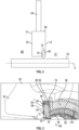
- a radially inner seal surface 102 is not a constant radius, but undulates between a maximum radius 104 and a minimum radius 106 defining, in some embodiments, a tri-lobe configuration which has three circumferential locations corresponding to the minimum radius 106. This configuration aids in preventing a full eccentric leakage pattern and resulting asymmetric thermal distortion off the components.
- the seal assembly 66 is assembled by first installing the forward seal carrier 80 to the rotor hub 62, then the seal body 78 is installed to the forward seal carrier 80. Next, the aft seal carrier 82 is installed to the forward seal carrier 80 by an interference fit. Finally, the snap ring 96 is installed over the aft seal carrier 82.
- the forward seal carrier 80, the seal body 78 and the aft seal carrier 82 are assembled into a unitary seal assembly 66. This completed seal assembly 66 is then installed to the rotor hub 62, and the snap ring 96 is installed to retain the seal assembly 66 to the rotor hub 62.
- the seal configurations disclosed herein reduce wear of the shaft and rotor components during operation of the engine 20 while maintaining an effective seal between the rotor 60 and the shaft 50.
Landscapes
- Engineering & Computer Science (AREA)
- Mechanical Engineering (AREA)
- General Engineering & Computer Science (AREA)
- Turbine Rotor Nozzle Sealing (AREA)
Applications Claiming Priority (1)
| Application Number | Priority Date | Filing Date | Title |
|---|---|---|---|
| US18/053,483 US20240151152A1 (en) | 2022-11-08 | 2022-11-08 | Seal for gas turbine engine |
Publications (1)
| Publication Number | Publication Date |
|---|---|
| EP4372208A1 true EP4372208A1 (de) | 2024-05-22 |
Family
ID=88745866
Family Applications (1)
| Application Number | Title | Priority Date | Filing Date |
|---|---|---|---|
| EP23208566.2A Pending EP4372208A1 (de) | 2022-11-08 | 2023-11-08 | Dichtung für gasturbinenmotor |
Country Status (2)
| Country | Link |
|---|---|
| US (1) | US20240151152A1 (de) |
| EP (1) | EP4372208A1 (de) |
Citations (6)
| Publication number | Priority date | Publication date | Assignee | Title |
|---|---|---|---|---|
| US5480162A (en) * | 1993-09-08 | 1996-01-02 | United Technologies Corporation | Axial load carrying brush seal |
| US6695314B1 (en) * | 1999-12-23 | 2004-02-24 | Mtu Aero Engines Gmbh | Brush seal |
| US20050040602A1 (en) * | 2003-08-18 | 2005-02-24 | Mtu Aero Engines Gmbh | Brush seal |
| US7445212B2 (en) * | 2000-04-13 | 2008-11-04 | Mtu Aero Engines Gmbh | Brush seal |
| US20180291815A1 (en) * | 2017-04-10 | 2018-10-11 | Rolls-Royce Corporation | Reduced friction intershaft seal assembly |
| FR3075861A1 (fr) * | 2017-12-22 | 2019-06-28 | Safran Aircraft Engines | Etancheite dynamique entre deux rotors d'une turbomachine d'aeronef |
Family Cites Families (28)
| Publication number | Priority date | Publication date | Assignee | Title |
|---|---|---|---|---|
| US3319929A (en) * | 1964-12-31 | 1967-05-16 | Gen Electric | Vibration damping means |
| DE2643886C2 (de) * | 1976-09-29 | 1978-02-09 | Kraftwerk Union AG, 4330 Mülheim | Gasturbinentäufer in Scheibenbauart |
| US4309145A (en) * | 1978-10-30 | 1982-01-05 | General Electric Company | Cooling air seal |
| US4211424A (en) * | 1979-04-16 | 1980-07-08 | Stein Philip C | Centrifugally compensated seal for sealing between concentric shafts |
| FR2603947B1 (fr) * | 1986-09-17 | 1990-11-30 | Snecma | Dispositif de maintien d'un joint d'etancheite sur un bout d'arbre et turbomachine le comportant |
| US5181728A (en) * | 1991-09-23 | 1993-01-26 | General Electric Company | Trenched brush seal |
| US6612809B2 (en) * | 2001-11-28 | 2003-09-02 | General Electric Company | Thermally compliant discourager seal |
| GB0226685D0 (en) * | 2002-11-15 | 2002-12-24 | Rolls Royce Plc | Sealing arrangement |
| US20090072486A1 (en) * | 2004-05-04 | 2009-03-19 | Rexnord Industries, Llc | Brush seal |
| DE102004038933A1 (de) * | 2004-08-11 | 2006-02-23 | Mtu Aero Engines Gmbh | Dichtungsanordnung |
| US9004495B2 (en) * | 2008-09-15 | 2015-04-14 | Stein Seal Company | Segmented intershaft seal assembly |
| US8388309B2 (en) * | 2008-09-25 | 2013-03-05 | Siemens Energy, Inc. | Gas turbine sealing apparatus |
| US9109703B2 (en) * | 2010-02-11 | 2015-08-18 | Kalsi Engineering, Inc. | Hydrodynamic backup ring |
| GB201111531D0 (en) * | 2011-07-06 | 2011-08-17 | Rolls Royce Plc | A sealing arrangement |
| EP3058176B1 (de) * | 2013-10-02 | 2020-08-26 | United Technologies Corporation | Gasturbinentriebwerk mit verdichterplattendeflektoren |
| DE102013222514A1 (de) * | 2013-11-06 | 2015-05-07 | MTU Aero Engines AG | Dichtungsanordnung für eine Strömungsmaschine |
| CN105765168B (zh) * | 2013-11-26 | 2017-10-24 | 通用电气公司 | 径向系紧螺栓支承弹簧 |
| US20160109025A1 (en) * | 2014-10-21 | 2016-04-21 | United Technologies Corporation | Seal ring |
| DE102016204213A1 (de) * | 2016-03-15 | 2017-09-21 | MTU Aero Engines AG | Dichtungsanordnung für Turbine |
| US10619742B2 (en) * | 2017-07-14 | 2020-04-14 | United Technologies Corporation | Ring seal arrangement with installation foolproofing |
| JP6764381B2 (ja) * | 2017-08-24 | 2020-09-30 | 三菱重工業株式会社 | 軸シール構造および一次冷却材循環ポンプ |
| US10920617B2 (en) * | 2018-08-17 | 2021-02-16 | Raytheon Technologies Corporation | Gas turbine engine seal ring assembly |
| CN113167126B (zh) * | 2018-10-09 | 2023-05-02 | 西门子能源全球两合公司 | 非接触密封组件中的副密封 |
| US10982770B2 (en) * | 2019-01-03 | 2021-04-20 | Raytheon Technologies Corporation | Hydrostatic seal with extended housing |
| US11028713B2 (en) * | 2019-04-03 | 2021-06-08 | Raytheon Technologies Corporation | Rotating carbon piston ring seal |
| US11149651B2 (en) * | 2019-08-07 | 2021-10-19 | Raytheon Technologies Corporation | Seal ring assembly for a gas turbine engine |
| US11193593B2 (en) * | 2019-09-03 | 2021-12-07 | Raytheon Technologies Corporation | Hydrostatic seal |
| US11542819B2 (en) * | 2021-02-17 | 2023-01-03 | Pratt & Whitney Canada Corp. | Split ring seal for gas turbine engine rotor |
-
2022
- 2022-11-08 US US18/053,483 patent/US20240151152A1/en not_active Abandoned
-
2023
- 2023-11-08 EP EP23208566.2A patent/EP4372208A1/de active Pending
Patent Citations (6)
| Publication number | Priority date | Publication date | Assignee | Title |
|---|---|---|---|---|
| US5480162A (en) * | 1993-09-08 | 1996-01-02 | United Technologies Corporation | Axial load carrying brush seal |
| US6695314B1 (en) * | 1999-12-23 | 2004-02-24 | Mtu Aero Engines Gmbh | Brush seal |
| US7445212B2 (en) * | 2000-04-13 | 2008-11-04 | Mtu Aero Engines Gmbh | Brush seal |
| US20050040602A1 (en) * | 2003-08-18 | 2005-02-24 | Mtu Aero Engines Gmbh | Brush seal |
| US20180291815A1 (en) * | 2017-04-10 | 2018-10-11 | Rolls-Royce Corporation | Reduced friction intershaft seal assembly |
| FR3075861A1 (fr) * | 2017-12-22 | 2019-06-28 | Safran Aircraft Engines | Etancheite dynamique entre deux rotors d'une turbomachine d'aeronef |
Also Published As
| Publication number | Publication date |
|---|---|
| US20240151152A1 (en) | 2024-05-09 |
Similar Documents
| Publication | Publication Date | Title |
|---|---|---|
| EP3734018B1 (de) | Dichtung für ein gasturbinentriebwerks-bauteil und zugehöriges verfahren | |
| US11092030B2 (en) | Adaptive case for a gas turbine engine | |
| EP3543469A1 (de) | Federdichtungsanordnung | |
| EP3786418A1 (de) | Hydrostatische dichtung mit dichtungsanschlägen | |
| EP3502497A1 (de) | Flexible vorbelastete kugellageranordnung | |
| EP3653915A1 (de) | Hilfe zur demontage einer dichtung | |
| EP3789588B1 (de) | Hydrostatische dichtung ausgerichtet mit der rotordrehrichtung | |
| EP3760838A1 (de) | Verstellbares schaufelsystem von gasturbinenmotoren und verfahren | |
| EP3190266B1 (de) | Gasturbine mit rotornabendichtung | |
| EP3822459B1 (de) | Deckbandsegment mit kühlungsnut | |
| EP3293358B1 (de) | Schaufelhalteanordnung für einen gasturbinenmotor | |
| EP3428408A1 (de) | Einsatzelement am ende einer verstellbaren schaufel in einem gasturbinentriebwerk | |
| EP3772570A1 (de) | Hydrostatische dichtung mit verlängertem trägerarm | |
| EP3748135A1 (de) | Buchse für eine variable leitschaufel einer gasturbine | |
| EP3708773A2 (de) | Dichtung für einen gasturbinenmotor | |
| EP3517738B1 (de) | Schaufelaussendeckband für ein gasturbinentriebwerk | |
| EP3623585A1 (de) | Abdeckung für die schaufelanordnung für einen gasturbinenmotor | |
| EP3611347B1 (de) | Gasturbinentriebwerk mit statorsegmenten | |
| EP4372208A1 (de) | Dichtung für gasturbinenmotor | |
| EP3760841B1 (de) | Mehrzweckdrehsicherungssperrbolzen | |
| EP3869006A1 (de) | Rotorscheibe mit integralem bohrungskorb | |
| EP3477061B1 (de) | Umlaufende spaltdichtung für statorsegment | |
| US12392251B2 (en) | Diametrically expandable/collapsible piston seal | |
| EP4560114A1 (de) | Kolbenringdichtung | |
| WO2014092909A1 (en) | Multi-piece blade for gas turbine engine |
Legal Events
| Date | Code | Title | Description |
|---|---|---|---|
| PUAI | Public reference made under article 153(3) epc to a published international application that has entered the european phase |
Free format text: ORIGINAL CODE: 0009012 |
|
| STAA | Information on the status of an ep patent application or granted ep patent |
Free format text: STATUS: THE APPLICATION HAS BEEN PUBLISHED |
|
| AK | Designated contracting states |
Kind code of ref document: A1 Designated state(s): AL AT BE BG CH CY CZ DE DK EE ES FI FR GB GR HR HU IE IS IT LI LT LU LV MC ME MK MT NL NO PL PT RO RS SE SI SK SM TR |
|
| STAA | Information on the status of an ep patent application or granted ep patent |
Free format text: STATUS: REQUEST FOR EXAMINATION WAS MADE |
|
| 17P | Request for examination filed |
Effective date: 20241122 |
|
| RBV | Designated contracting states (corrected) |
Designated state(s): AL AT BE BG CH CY CZ DE DK EE ES FI FR GB GR HR HU IE IS IT LI LT LU LV MC ME MK MT NL NO PL PT RO RS SE SI SK SM TR |