EP4372232A1 - Elektronische wasserpumpe - Google Patents
Elektronische wasserpumpe Download PDFInfo
- Publication number
- EP4372232A1 EP4372232A1 EP22841378.7A EP22841378A EP4372232A1 EP 4372232 A1 EP4372232 A1 EP 4372232A1 EP 22841378 A EP22841378 A EP 22841378A EP 4372232 A1 EP4372232 A1 EP 4372232A1
- Authority
- EP
- European Patent Office
- Prior art keywords
- gasket
- mounting portion
- disposed
- water pump
- electronic water
- Prior art date
- Legal status (The legal status is an assumption and is not a legal conclusion. Google has not performed a legal analysis and makes no representation as to the accuracy of the status listed.)
- Pending
Links
Images


Classifications
-
- F—MECHANICAL ENGINEERING; LIGHTING; HEATING; WEAPONS; BLASTING
- F04—POSITIVE - DISPLACEMENT MACHINES FOR LIQUIDS; PUMPS FOR LIQUIDS OR ELASTIC FLUIDS
- F04D—NON-POSITIVE-DISPLACEMENT PUMPS
- F04D29/00—Details, component parts, or accessories
- F04D29/40—Casings; Connections of working fluid
- F04D29/42—Casings; Connections of working fluid for radial or helico-centrifugal pumps
- F04D29/426—Casings; Connections of working fluid for radial or helico-centrifugal pumps especially adapted for liquid pumps
-
- F—MECHANICAL ENGINEERING; LIGHTING; HEATING; WEAPONS; BLASTING
- F04—POSITIVE - DISPLACEMENT MACHINES FOR LIQUIDS; PUMPS FOR LIQUIDS OR ELASTIC FLUIDS
- F04D—NON-POSITIVE-DISPLACEMENT PUMPS
- F04D1/00—Radial-flow pumps, e.g. centrifugal pumps; Helico-centrifugal pumps
-
- F—MECHANICAL ENGINEERING; LIGHTING; HEATING; WEAPONS; BLASTING
- F04—POSITIVE - DISPLACEMENT MACHINES FOR LIQUIDS; PUMPS FOR LIQUIDS OR ELASTIC FLUIDS
- F04D—NON-POSITIVE-DISPLACEMENT PUMPS
- F04D13/00—Pumping installations or systems
- F04D13/02—Units comprising pumps and their driving means
- F04D13/06—Units comprising pumps and their driving means the pump being electrically driven
- F04D13/0606—Canned motor pumps
- F04D13/0633—Details of the bearings
-
- F—MECHANICAL ENGINEERING; LIGHTING; HEATING; WEAPONS; BLASTING
- F04—POSITIVE - DISPLACEMENT MACHINES FOR LIQUIDS; PUMPS FOR LIQUIDS OR ELASTIC FLUIDS
- F04D—NON-POSITIVE-DISPLACEMENT PUMPS
- F04D25/00—Pumping installations or systems
- F04D25/02—Units comprising pumps and their driving means
- F04D25/06—Units comprising pumps and their driving means the pump being electrically driven
-
- F—MECHANICAL ENGINEERING; LIGHTING; HEATING; WEAPONS; BLASTING
- F04—POSITIVE - DISPLACEMENT MACHINES FOR LIQUIDS; PUMPS FOR LIQUIDS OR ELASTIC FLUIDS
- F04D—NON-POSITIVE-DISPLACEMENT PUMPS
- F04D29/00—Details, component parts, or accessories
- F04D29/04—Shafts or bearings, or assemblies thereof
- F04D29/043—Shafts
-
- F—MECHANICAL ENGINEERING; LIGHTING; HEATING; WEAPONS; BLASTING
- F04—POSITIVE - DISPLACEMENT MACHINES FOR LIQUIDS; PUMPS FOR LIQUIDS OR ELASTIC FLUIDS
- F04D—NON-POSITIVE-DISPLACEMENT PUMPS
- F04D29/00—Details, component parts, or accessories
- F04D29/04—Shafts or bearings, or assemblies thereof
- F04D29/046—Bearings
-
- F—MECHANICAL ENGINEERING; LIGHTING; HEATING; WEAPONS; BLASTING
- F04—POSITIVE - DISPLACEMENT MACHINES FOR LIQUIDS; PUMPS FOR LIQUIDS OR ELASTIC FLUIDS
- F04D—NON-POSITIVE-DISPLACEMENT PUMPS
- F04D29/00—Details, component parts, or accessories
- F04D29/40—Casings; Connections of working fluid
- F04D29/42—Casings; Connections of working fluid for radial or helico-centrifugal pumps
- F04D29/426—Casings; Connections of working fluid for radial or helico-centrifugal pumps especially adapted for liquid pumps
- F04D29/4273—Casings; Connections of working fluid for radial or helico-centrifugal pumps especially adapted for liquid pumps suction eyes
-
- F—MECHANICAL ENGINEERING; LIGHTING; HEATING; WEAPONS; BLASTING
- F04—POSITIVE - DISPLACEMENT MACHINES FOR LIQUIDS; PUMPS FOR LIQUIDS OR ELASTIC FLUIDS
- F04D—NON-POSITIVE-DISPLACEMENT PUMPS
- F04D13/00—Pumping installations or systems
- F04D13/02—Units comprising pumps and their driving means
- F04D13/06—Units comprising pumps and their driving means the pump being electrically driven
-
- F—MECHANICAL ENGINEERING; LIGHTING; HEATING; WEAPONS; BLASTING
- F04—POSITIVE - DISPLACEMENT MACHINES FOR LIQUIDS; PUMPS FOR LIQUIDS OR ELASTIC FLUIDS
- F04D—NON-POSITIVE-DISPLACEMENT PUMPS
- F04D29/00—Details, component parts, or accessories
- F04D29/08—Sealings
- F04D29/083—Sealings especially adapted for elastic fluid pumps
-
- F—MECHANICAL ENGINEERING; LIGHTING; HEATING; WEAPONS; BLASTING
- F04—POSITIVE - DISPLACEMENT MACHINES FOR LIQUIDS; PUMPS FOR LIQUIDS OR ELASTIC FLUIDS
- F04D—NON-POSITIVE-DISPLACEMENT PUMPS
- F04D29/00—Details, component parts, or accessories
- F04D29/08—Sealings
- F04D29/086—Sealings especially adapted for liquid pumps
-
- F—MECHANICAL ENGINEERING; LIGHTING; HEATING; WEAPONS; BLASTING
- F04—POSITIVE - DISPLACEMENT MACHINES FOR LIQUIDS; PUMPS FOR LIQUIDS OR ELASTIC FLUIDS
- F04D—NON-POSITIVE-DISPLACEMENT PUMPS
- F04D29/00—Details, component parts, or accessories
- F04D29/40—Casings; Connections of working fluid
- F04D29/42—Casings; Connections of working fluid for radial or helico-centrifugal pumps
- F04D29/4206—Casings; Connections of working fluid for radial or helico-centrifugal pumps especially adapted for elastic fluid pumps
-
- F—MECHANICAL ENGINEERING; LIGHTING; HEATING; WEAPONS; BLASTING
- F05—INDEXING SCHEMES RELATING TO ENGINES OR PUMPS IN VARIOUS SUBCLASSES OF CLASSES F01-F04
- F05D—INDEXING SCHEME FOR ASPECTS RELATING TO NON-POSITIVE-DISPLACEMENT MACHINES OR ENGINES, GAS-TURBINES OR JET-PROPULSION PLANTS
- F05D2250/00—Geometry
- F05D2250/50—Inlet or outlet
- F05D2250/51—Inlet
-
- F—MECHANICAL ENGINEERING; LIGHTING; HEATING; WEAPONS; BLASTING
- F05—INDEXING SCHEMES RELATING TO ENGINES OR PUMPS IN VARIOUS SUBCLASSES OF CLASSES F01-F04
- F05D—INDEXING SCHEME FOR ASPECTS RELATING TO NON-POSITIVE-DISPLACEMENT MACHINES OR ENGINES, GAS-TURBINES OR JET-PROPULSION PLANTS
- F05D2260/00—Function
- F05D2260/30—Retaining components in desired mutual position
- F05D2260/35—Reducing friction between regenerative impeller discs and casing walls
-
- F—MECHANICAL ENGINEERING; LIGHTING; HEATING; WEAPONS; BLASTING
- F16—ENGINEERING ELEMENTS AND UNITS; GENERAL MEASURES FOR PRODUCING AND MAINTAINING EFFECTIVE FUNCTIONING OF MACHINES OR INSTALLATIONS; THERMAL INSULATION IN GENERAL
- F16J—PISTONS; CYLINDERS; SEALINGS
- F16J15/00—Sealings
-
- F—MECHANICAL ENGINEERING; LIGHTING; HEATING; WEAPONS; BLASTING
- F16—ENGINEERING ELEMENTS AND UNITS; GENERAL MEASURES FOR PRODUCING AND MAINTAINING EFFECTIVE FUNCTIONING OF MACHINES OR INSTALLATIONS; THERMAL INSULATION IN GENERAL
- F16J—PISTONS; CYLINDERS; SEALINGS
- F16J15/00—Sealings
- F16J15/02—Sealings between relatively-stationary surfaces
- F16J15/06—Sealings between relatively-stationary surfaces with solid packing compressed between sealing surfaces
- F16J15/061—Sealings between relatively-stationary surfaces with solid packing compressed between sealing surfaces with positioning means
Definitions
- the present invention relates to the technical field of water pumps, and in particular to an electronic water pump.
- an impeller assembly of an electronic water pump is installed on a pump head, when the impeller assembly rotates, a friction force between the impeller assembly and the pump head is relatively large, thereby being prone to generating relatively large abrasion.
- a gasket is generally disposed between the impeller assembly and the pump head, so that the gasket isolates the impeller assembly from the pump head.
- the gasket rotates accordingly, and the gasket rubs and collides with the impeller assembly or the pump head, thereby generating relatively large noise, and thus affecting the normal use of a user.
- the present invention provides an electronic water pump, so as to solve the problem that an electronic water pump in the prior art is prone to generating relatively large noise.
- the present invention provides an electronic water pump, including: a pump head, wherein a mounting portion is disposed on the pump head; a pump housing, which is used for sealing the pump housing; an isolation sleeve disposed between the pump head and the pump housing; an impeller assembly disposed between the pump head and the isolation sleeve; a first gasket, which is disposed at an end of the mounting portion that is close to the impeller assembly, wherein the first gasket is used for isolating the mounting portion from the impeller assembly; and a rotation stopping structure disposed between the first gasket and the mounting portion, wherein the rotation stopping structure is capable of limiting a rotation of the first gasket relative to the mounting portion.
- the pump head is provided with the mounting portion, the impeller assembly is disposed between the pump head and the isolation sleeve, the first gasket is disposed at the end of the mounting portion that is close to the impeller assembly, the first gasket is used for isolating the mounting portion from the impeller assembly, the rotation stopping structure is disposed between the first gasket and the mounting portion, and the rotation stopping structure is capable of limiting the rotation of the first gasket relative to the mounting portion.
- the first gasket includes a gasket body and an extension portion
- the gasket body is located at an end portion of the mounting portion that is close to the impeller assembly
- the extension portion is connected with an edge of the gasket body
- the extension portion extends in a direction away from the impeller assembly
- a side wall of the mounting portion is provided with at least one limiting rib
- the extension portion cooperates with the at least one limiting rib to form the rotation stopping structure.
- the extension portion and the limiting rib are simple in structure and easy to process.
- the extension portion may cooperate with the limiting rib to limit the rotation of the first gasket.
- the mounting portion is provided with a first clamping structure
- the first gasket is provided with a second clamping structure
- the first clamping structure is clamped with the second clamping structure, so as to limit a displacement of the first gasket in the axial direction of the mounting portion.
- the first gasket does not move in the axial direction of the mounting portion, so that the first gasket can be prevented from colliding with the impeller assembly or the pump head, thereby further reducing the noise of the electronic water pump during operation.
- the second clamping structure is a protruding structure disposed on the extension portion, and the protruding structure extends towards the mounting portion.
- the protruding structure is disposed on the extension portion, thereby being simple in structure and easy to process.
- the first clamping structure is a recessed structure disposed on a side wall of the mounting portion, and the protruding structure is matched and clamped with the recessed structure.
- the protruding structure is clamped in the recessed structure, thereby preventing the first gasket from moving in the axial direction of the mounting portion.
- the mounting portion has a first segment and a second segment, which are connected with each other, the first segment is disposed close to the impeller assembly, a diameter of the first segment is greater than a diameter of the second segment, a step surface is formed at a joint of the first segment and the second segment, and the step surface is of the recessed structure.
- the protruding structure is clamped on the second segment, thereby limiting the first gasket from moving in the axial direction of the mounting portion. Since the step surface is of the recessed structure, the processing difficulty is reduced.
- the extension portion includes a plurality of clamping jaws, and the plurality of clamping jaws are disposed at intervals in a circumferential direction of the first gasket.
- the plurality of clamping jaws are uniformly stressed to prevent the first gasket from skewing, so as to improve the stability of the overall connection.
- the limiting ribs are annularly disposed at intervals in the circumferential direction of the mounting portion, the number of the clamping jaws is the same as that of the limiting ribs, and the clamping jaws and the limiting ribs are disposed on a one-to-one correspondence basis.
- the structure is simple, the installation is convenient, and the processing difficulty is low.
- the electronic water pump further includes a second gasket, and the second gasket is disposed between the impeller assembly and the isolation sleeve.
- the second gasket is used for isolating the impeller assembly from the isolation sleeve, so as to prevent abrasion caused by the mutual friction between the impeller assembly and the isolation sleeve.
- the impeller assembly includes an impeller and a connecting rod, the connecting rod is used for connecting the impeller and a rotor assembly, and the connecting rod and the impeller are of an integrated structure; and the electronic water pump further includes the rotor assembly and a rotating shaft, the connecting rod, the impeller and the rotor assembly are sleeved on the rotating shaft, and two ends of the rotating shaft are respectively fixed to the mounting portion and the isolation sleeve. In this way, the impeller assembly can be conveniently installed in the isolation sleeve, and the installation efficiency is thus improved.
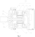
- an embodiment of the present invention provides an electronic water pump, including: a pump head 10, a pump housing 20, an isolation sleeve 30, an impeller assembly 40, a first gasket 50 and a rotation stopping structure.
- the pump head 10 is provided with a mounting portion 11; the pump head 10 is used for sealing the pump housing 20; the isolation sleeve 30 is disposed between the pump head 10 and the pump housing 20; the impeller assembly 40 is disposed between the pump head 10 and the isolation sleeve 30; the first gasket 50 is disposed at an end of the mounting portion 11 that is close to the impeller assembly 40, and the first gasket 50 is used for isolating the mounting portion 11 from the impeller assembly 40; and the rotation stopping structure is disposed between the first gasket 50 and the mounting portion 11, and the rotation stopping structure is capable of limiting a rotation of the first gasket 50 relative to the mounting portion 11.
- the mounting portion 11 is used for mounting the impeller assembly, optionally, the mounting portion 11 is disposed at a middle of an inner side of the pump head 10, and the mounting portion 11 is of a protruding structure.
- the isolation sleeve 30 divides an interior of the pump housing 20 into two spaces, the impeller assembly 40 is disposed between the pump head 10 and the isolation sleeve, and the impeller assembly 40 is disposed on the mounting portion 11 of the pump head 10.
- the first gasket 50 isolates the mounting portion 11 from the impeller assembly 40, so as to prevent mutual friction therebetween. When the impeller assembly 40 rotates, the rotation stopping structure may prevent the first gasket 50 from rotating along with the impeller assembly 40, thereby reducing an operation noise of the electronic water pump.
- the pump head 10 is provided with the mounting portion 11, the impeller assembly 40 is disposed between the pump head 10 and the isolation sleeve 30, the first gasket 50 is disposed at the end of the mounting portion 11 that is close to the impeller assembly 40, the first gasket 50 is used for isolating the mounting portion 11 from the impeller assembly 40, the rotation stopping structure is disposed between the first gasket 50 and the mounting portion 11, and the rotation stopping structure is capable of limiting the rotation of the first gasket 50 relative to the mounting portion 11.
- the impeller assembly 40 can be prevented from, while rotating, driving the first gasket 50 to rotate, thereby avoiding friction and collision between the first gasket 50 and the impeller assembly 40 or the pump head 10, and thus reducing the noise of the electronic water pump during operation.
- the first gasket 50 includes a gasket body 51 and an extension portion 52
- the gasket body 51 is located at an end portion of the mounting portion 11 that is close to the impeller assembly 40
- the extension portion 52 is connected with an edge of the gasket body 51
- the extension portion 52 extends in a direction away from the impeller assembly 40
- a side wall of the mounting portion 11 is provided with at least one limiting rib 60
- the extension portion 52 cooperates with the at least one limiting rib 60 to form the rotation stopping structure.
- the gasket body 51 is used for isolating the mounting portion 11 from the impeller assembly 40.
- the extension portion 52 cooperates with the limiting rib 60, the limiting rib 60 limits the extension portion 52 from rotating in a circumferential direction of the mounting portion 11, thereby limiting the rotation of the first gasket 50.
- the gasket body 51 and the extension portion 52 are of an integrally formed structure.
- the first gasket 50 is made of a wear-resistant material having a small surface friction coefficient such as stainless steel, so as to further reduce the friction between the first gasket 50 and the mounting portion 11 and between the first gasket 50 and the impeller assembly 40. As shown in Fig. 2 and Fig.
- the mounting portion 11 is provided with a first clamping structure
- the first gasket 50 is provided with a second clamping structure
- the first clamping structure is clamped with the second clamping structure to limit a displacement of the first gasket 50 in an axial direction of the mounting portion 11.
- the second clamping structure is a protruding structure 521 disposed on the extension portion 52, and the protruding structure 521 extends towards the mounting portion 11.
- the protruding structure 521 may be a projection structure.
- the protruding structure 521 is a bent structure, and the bent structure is V-shaped and is bent towards the mounting portion 11. In the above solution, the structure is simple, and the first gasket 50 is conveniently processed.
- the first clamping structure is a recessed structure disposed on a side wall of the mounting portion 11, and the protruding structure 521 is matched and clamped with the recessed structure.
- the protruding structure 521 is clamped in the recessed structure, and the protruding structure 521 abuts against the recessed structure, so that the first gasket 50 can be limited from moving in the axial direction of the mounting portion 11.
- the recessed structure may be a groove structure, and may also be set as step structure, as long as the recessed structure be matched and clamped with the second clamping structure.
- the mounting portion 11 has a first segment 111 and a second segment 112, which are connected with each other, the first segment 111 is disposed close to the impeller assembly 40, a diameter of the first segment 111 is greater than a diameter of the second segment 112, a step surface is formed at a joint of the first segment 111 and the second segment 112, and the step surface forms the recessed structure.
- the protruding structure 521 is clamped on the second segment 112, thereby limiting the first gasket 50 from moving in the axial direction of the mounting portion 11. Since the step surface is of the recessed structure, the processing difficulty is reduced.
- the recessed structure may also be an annular groove or a local groove formed in the side wall of the mounting portion 11.
- the extension portion 52 includes a plurality of clamping jaws, and the plurality of clamping jaws are disposed at intervals in the circumferential direction of the first gasket 50. That is, the plurality of clamping jaws are clamped on the side wall of the mounting portion 11 and are disposed at intervals along the side wall of the mounting portion 11, and the plurality of clamping jaws are uniformly stressed to prevent the first gasket 50 from skewing, so as to improve a stability of the overall connection.
- the extension portion 52 is set to be of a clamping jaw structure, thereby being simple in structure and convenient to process.
- each clamping jaw is clamped between the limiting ribs 60, so as to limit, by the limiting ribs 60, the clamping jaw from rotating clockwise or counterclockwise around the mounting portion 11.
- the rotation stopping structure includes the limiting ribs 60 and the clamping jaws, thereby being simple in structure, convenient to install and low in processing difficulty.
- the limiting rib 60 extends in a radial direction of the mounting portion 11 and is connected with the pump head 10.
- the electronic water pump further includes a second gasket 70, and the second gasket 70 is disposed between the impeller assembly 40 and the isolation sleeve 30.
- the second gasket 70 is used for isolating the impeller assembly 40 from the isolation sleeve 30, so as to prevent abrasion caused by a mutual friction between the impeller assembly 40 and the isolation sleeve 30.
- the second gasket 70 is made of a material having a small surface friction coefficient such as stainless steel, so as to reduce the friction between the second gasket 70 and the impeller assembly 40 and between the second gasket 70 and the isolation sleeve 30.
- the impeller assembly 40 includes an impeller 41 and a connecting rod 42, the connecting rod 42 is used for connecting the impeller 41 and a rotor assembly 43, and the connecting rod 42 and the impeller 41 are of an integrated structure;
- the electronic water pump further includes the rotor assembly 43 and a rotating shaft 44, the connecting rod 42, the impeller 41 and the rotor assembly 43 are sleeved on the rotating shaft 44, and two ends of the rotating shaft 44 are respectively fixed to the mounting portion 11 and the isolation sleeve 30.
- the impeller 41 is disposed close to the mounting portion 11, the connecting rod 42 is connected with the end of the impeller 41 that is away from the mounting portion 11, and the rotor assembly 43 is sleeved on the connecting rod 42. In this way, the impeller assembly 40 can be conveniently installed in the isolation sleeve 30, and the installation efficiency is thus improved.
- the pump head 10 is provided with the mounting portion 11, the impeller assembly 40 is disposed between the pump head 10 and the isolation sleeve 30, the first gasket 50 is disposed at the end of the mounting portion 11 that is close to the impeller assembly 40, the first gasket 50 is used for isolating the mounting portion 11 from the impeller assembly 40, the rotation stopping structure is disposed between the first gasket 50 and the mounting portion 11, therefore by providing the rotation stopping structure, the impeller assembly 40 can be prevented from, while rotating, from driving the first gasket 50 to rotate, thereby reducing the noise of the electronic water pump during operation; and the rotation stopping structure includes the extension portion 52 connected with the first gasket body 51, and the limiting ribs 60 disposed on the side wall of the mounting portion 11, the extension portion 52 includes the plurality of clamping jaws, the clamping jaws and the limiting ribs 60 are disposed on the one-to-one correspondence basis, the limiting ribs 60 limit the first gasket 50 from rotating clockwise and counterclockwise along the mounting portion 11,
- orientation or position relationships indicated by orientation words such as “front, back, upper, lower, left, right", “transverse, longitudinal, vertical, horizontal” and “top, bottom” and the like are generally orientation or position relationships shown on the basis of the drawings, and are merely for the convenience of describing the present invention and simplifying the description, in the absence of opposite statements, these orientation words do not indicate or imply that the referred apparatuses or elements must have specific orientations or must be constructed and operated in specific orientations, and thus cannot be construed as limiting the protection scope of the present invention; and the orientation words “inside and outside” refer to the inside and outside of the contours of the components themselves.
- spatially relative terms such as “on”, “above”, “on the surface”, “over” and the like, may be used herein to describe spatial position relationships between one device or feature and other devices or features shown in the figures. It should be understood that, the spatially relative terms are intended to contain different orientations of a device in use or operation in addition to the orientations described in the figures. For example, if the device in the figures is turned over, the device, which is described as “above other devices or structures” or “over other devices or structures” would then be positioned as “below other devices or structures” or “beneath other devices or structures”. Thus, the exemplary term “above” may include both orientations of “above” and “below”. The device may also be otherwise positioned (rotated by 90 degrees or at other orientations), and the spatially relative descriptions used herein are interpreted accordingly.
Landscapes
- Engineering & Computer Science (AREA)
- Mechanical Engineering (AREA)
- General Engineering & Computer Science (AREA)
- Structures Of Non-Positive Displacement Pumps (AREA)
Applications Claiming Priority (2)
| Application Number | Priority Date | Filing Date | Title |
|---|---|---|---|
| CN202121590593.3U CN215109532U (zh) | 2021-07-13 | 2021-07-13 | 电子水泵 |
| PCT/CN2022/105216 WO2023284743A1 (zh) | 2021-07-13 | 2022-07-12 | 电子水泵 |
Publications (2)
| Publication Number | Publication Date |
|---|---|
| EP4372232A1 true EP4372232A1 (de) | 2024-05-22 |
| EP4372232A4 EP4372232A4 (de) | 2024-11-13 |
Family
ID=79320759
Family Applications (1)
| Application Number | Title | Priority Date | Filing Date |
|---|---|---|---|
| EP22841378.7A Pending EP4372232A4 (de) | 2021-07-13 | 2022-07-12 | Elektronische wasserpumpe |
Country Status (4)
| Country | Link |
|---|---|
| US (1) | US20240318664A1 (de) |
| EP (1) | EP4372232A4 (de) |
| CN (1) | CN215109532U (de) |
| WO (1) | WO2023284743A1 (de) |
Families Citing this family (2)
| Publication number | Priority date | Publication date | Assignee | Title |
|---|---|---|---|---|
| CN215109532U (zh) * | 2021-07-13 | 2021-12-10 | 盾安汽车热管理科技有限公司 | 电子水泵 |
| CN116677612A (zh) * | 2023-05-02 | 2023-09-01 | 东莞市深鹏电子有限公司 | 泵头及应用其的电子水泵 |
Family Cites Families (36)
| Publication number | Priority date | Publication date | Assignee | Title |
|---|---|---|---|---|
| US2004967A (en) * | 1934-07-24 | 1935-06-18 | Ideal Hose Coupling Company | Hose coupling |
| JP2530220Y2 (ja) * | 1990-01-10 | 1997-03-26 | 臼井国際産業株式会社 | 細径配管接続用コネクター |
| JP2540559Y2 (ja) * | 1991-05-20 | 1997-07-09 | 清原 まさ子 | 管継手用リテーナ |
| US5366261A (en) * | 1992-04-27 | 1994-11-22 | Fujikin Incorporated | Pipe joint with a gasket retainer |
| US5993176A (en) * | 1997-06-30 | 1999-11-30 | Furon Company | Magnetically-driven centrifugal pump |
| JP4034077B2 (ja) * | 2002-01-30 | 2008-01-16 | カルソニックカンセイ株式会社 | キャンドポンプ |
| JP4829024B2 (ja) * | 2006-07-25 | 2011-11-30 | アスモ株式会社 | ウォータポンプ |
| JP2008128076A (ja) * | 2006-11-20 | 2008-06-05 | Aisan Ind Co Ltd | 流体ポンプ |
| DE102007043600A1 (de) * | 2007-09-13 | 2009-03-19 | Robert Bosch Gmbh | Pumpenrotor für eine Spaltrohrpumpe |
| DE102008064162B4 (de) * | 2008-12-19 | 2013-06-06 | Bühler Motor GmbH | Kreiselpumpe mit einer feststehenden Achse |
| JP5465098B2 (ja) * | 2010-06-14 | 2014-04-09 | 三菱電機株式会社 | ポンプ及びヒートポンプ装置 |
| US9360015B2 (en) * | 2012-07-16 | 2016-06-07 | Magna Powertrain Of America, Inc. | Submerged rotor electric water pump with structural wetsleeve |
| US10291091B2 (en) * | 2014-09-25 | 2019-05-14 | Magna Powertrain Fpc Limited Partnership | Electric fluid pump with improved rotor unit, rotor unit therefor and methods of construction thereof |
| CN106151055B (zh) * | 2015-03-26 | 2019-06-07 | 浙江三花汽车零部件有限公司 | 电驱动泵 |
| CN105221441A (zh) * | 2015-09-18 | 2016-01-06 | 河南省西峡汽车水泵股份有限公司 | 一种低能耗高寿命的汽车电动水泵 |
| CN205349770U (zh) * | 2015-12-10 | 2016-06-29 | 上海边锋泵业制造有限公司 | 一种高效磁力泵 |
| EP3246574B1 (de) * | 2016-05-17 | 2018-12-19 | Xylem IP Management S.à.r.l. | Pumpe zum pumpen einer flüssigkeit sowie laufradanordnung |
| CN205937109U (zh) * | 2016-08-12 | 2017-02-08 | 珠海格力节能环保制冷技术研究中心有限公司 | 压缩机及具有其的空调器 |
| CN106089705B (zh) * | 2016-08-12 | 2018-02-27 | 珠海格力节能环保制冷技术研究中心有限公司 | 压缩机及具有其的空调器 |
| CN113202776B (zh) * | 2017-08-23 | 2023-09-15 | 浙江三花智能控制股份有限公司 | 电动泵 |
| DE102018211541A1 (de) * | 2018-07-11 | 2020-01-16 | Magna Powertrain Bad Homburg GmbH | Wasserpumpe |
| CN110873061B (zh) * | 2018-08-29 | 2023-08-01 | 广东德昌电机有限公司 | 泵体及用于泵体的转子组件的制造方法 |
| CN109162963A (zh) * | 2018-10-19 | 2019-01-08 | 谢启波 | 潜水泵上的泵头及由其所构成的潜水泵泵头组件 |
| KR20200111514A (ko) * | 2019-03-19 | 2020-09-29 | 주식회사 코아비스 | 워터 펌프 |
| CN111725934B (zh) * | 2019-03-22 | 2024-04-23 | 广东德昌电机有限公司 | 流体泵 |
| DE102019204226B4 (de) * | 2019-03-27 | 2022-06-09 | Hanon Systems Efp Deutschland Gmbh | Stecker füreine Steckverbindung an einer elektrischen Einheit, sowie Verfahren zur Herstel-lung eines Steckers für eine Steckverbindung an einer elektrischen Einheit |
| TWI704291B (zh) * | 2019-08-12 | 2020-09-11 | 訊凱國際股份有限公司 | 磁驅泵浦 |
| KR102221809B1 (ko) * | 2019-09-16 | 2021-03-03 | 주식회사 코아비스 | 제어부 일체형 모터 및 이를 포함한 워터 펌프 |
| CN112524048A (zh) * | 2019-09-18 | 2021-03-19 | 广东德昌电机有限公司 | 液体泵 |
| US20220399768A1 (en) * | 2020-01-24 | 2022-12-15 | Mitsubishi Electric Corporation | Rotor, motor, pump, refrigeration cycle apparatus, and manufacturing method of rotor |
| CN213341784U (zh) * | 2020-08-19 | 2021-06-01 | 盾安汽车热管理科技有限公司 | 转子组件及电子水泵 |
| CN112268004B (zh) * | 2020-11-02 | 2025-03-14 | 江苏朗信电气股份有限公司 | 一种大功率无刷电子水泵 |
| KR102365863B1 (ko) * | 2021-06-09 | 2022-02-23 | 주식회사 코아비스 | 워터 펌프 |
| CN215109532U (zh) * | 2021-07-13 | 2021-12-10 | 盾安汽车热管理科技有限公司 | 电子水泵 |
| KR102737182B1 (ko) * | 2022-08-10 | 2024-12-04 | 주식회사 코아비스 | 워터 펌프 |
| US11781566B1 (en) * | 2022-11-23 | 2023-10-10 | Coavis | Water pump and manufacturing method thereof |
-
2021
- 2021-07-13 CN CN202121590593.3U patent/CN215109532U/zh active Active
-
2022
- 2022-07-12 EP EP22841378.7A patent/EP4372232A4/de active Pending
- 2022-07-12 US US18/578,746 patent/US20240318664A1/en active Pending
- 2022-07-12 WO PCT/CN2022/105216 patent/WO2023284743A1/zh not_active Ceased
Also Published As
| Publication number | Publication date |
|---|---|
| EP4372232A4 (de) | 2024-11-13 |
| CN215109532U (zh) | 2021-12-10 |
| US20240318664A1 (en) | 2024-09-26 |
| WO2023284743A1 (zh) | 2023-01-19 |
Similar Documents
| Publication | Publication Date | Title |
|---|---|---|
| EP4372232A1 (de) | Elektronische wasserpumpe | |
| EP1908959B1 (de) | Pumpenrad-Kupplungsvorrichtung mit eingeschränkter freier Bewegung | |
| KR102463189B1 (ko) | 에어 포일 베어링 조립체 | |
| EP3832139A1 (de) | Hochtouriger lüfter mit lagerdämpfern | |
| CN115603503B (zh) | 驱动装置、控制方法、离心压缩机及存储介质 | |
| CN107565777B (zh) | 一种永磁电机的转子安装工装 | |
| EP3102831B1 (de) | Druckleitung mit einem elastischen element sowie vertikal hängende pumpe | |
| CN105252326B (zh) | 定位撑紧装置 | |
| CN104676004B (zh) | 一种液压泵的整体密封装置 | |
| US10598215B2 (en) | Electric motor having seizure-resistant dynamic pressure gas bearing | |
| EP3657025A1 (de) | Montagestruktur für ein querstromlaufrad, luftkanalanordnung und vorrichtung mit dem querstromlaufrad | |
| EP4624787A1 (de) | Befestigungselement und ventilvorrichtung damit | |
| CN108443233B (zh) | 具有减振结构的风扇框体及其风扇 | |
| CN109084503B (zh) | 分液器固定装置及旋转压缩机 | |
| CN208651476U (zh) | 一种多模离合器 | |
| CN213358049U (zh) | 滚筒机构及洗衣机 | |
| CN219268598U (zh) | 防火塑封电机 | |
| CN104633890A (zh) | 电机转轴的稳定装置、面板组件及空调器 | |
| CN112824689B (zh) | 螺母组件以及电子膨胀阀 | |
| CN213521431U (zh) | 一种外转子电机 | |
| WO2024065782A1 (en) | Connection assembly for encoder and encoder | |
| CN106972680B (zh) | 轴承组件及具有其的电机 | |
| CN213879404U (zh) | 一种转子连接结构及旋变 | |
| CN217055639U (zh) | 风机及电器设备 | |
| CN216742091U (zh) | 风扇组件及挂脖风扇 |
Legal Events
| Date | Code | Title | Description |
|---|---|---|---|
| STAA | Information on the status of an ep patent application or granted ep patent |
Free format text: STATUS: THE INTERNATIONAL PUBLICATION HAS BEEN MADE |
|
| PUAI | Public reference made under article 153(3) epc to a published international application that has entered the european phase |
Free format text: ORIGINAL CODE: 0009012 |
|
| STAA | Information on the status of an ep patent application or granted ep patent |
Free format text: STATUS: REQUEST FOR EXAMINATION WAS MADE |
|
| 17P | Request for examination filed |
Effective date: 20240118 |
|
| AK | Designated contracting states |
Kind code of ref document: A1 Designated state(s): AL AT BE BG CH CY CZ DE DK EE ES FI FR GB GR HR HU IE IS IT LI LT LU LV MC MK MT NL NO PL PT RO RS SE SI SK SM TR |
|
| REG | Reference to a national code |
Ref country code: DE Ref legal event code: R079 Free format text: PREVIOUS MAIN CLASS: F04D0029240000 Ipc: F04D0001000000 |
|
| DAV | Request for validation of the european patent (deleted) | ||
| DAX | Request for extension of the european patent (deleted) | ||
| A4 | Supplementary search report drawn up and despatched |
Effective date: 20241010 |
|
| RIC1 | Information provided on ipc code assigned before grant |
Ipc: F04D 29/42 20060101ALI20241004BHEP Ipc: F04D 29/046 20060101ALI20241004BHEP Ipc: F04D 1/00 20060101AFI20241004BHEP |