EP4372255A1 - Soupape de distribution - Google Patents
Soupape de distribution Download PDFInfo
- Publication number
- EP4372255A1 EP4372255A1 EP23210086.7A EP23210086A EP4372255A1 EP 4372255 A1 EP4372255 A1 EP 4372255A1 EP 23210086 A EP23210086 A EP 23210086A EP 4372255 A1 EP4372255 A1 EP 4372255A1
- Authority
- EP
- European Patent Office
- Prior art keywords
- switching element
- collective
- distribution valve
- connection channel
- individual
- Prior art date
- Legal status (The legal status is an assumption and is not a legal conclusion. Google has not performed a legal analysis and makes no representation as to the accuracy of the status listed.)
- Pending
Links
Images


Classifications
-
- F—MECHANICAL ENGINEERING; LIGHTING; HEATING; WEAPONS; BLASTING
- F16—ENGINEERING ELEMENTS AND UNITS; GENERAL MEASURES FOR PRODUCING AND MAINTAINING EFFECTIVE FUNCTIONING OF MACHINES OR INSTALLATIONS; THERMAL INSULATION IN GENERAL
- F16K—VALVES; TAPS; COCKS; ACTUATING-FLOATS; DEVICES FOR VENTING OR AERATING
- F16K11/00—Multiple-way valves, e.g. mixing valves; Pipe fittings incorporating such valves
- F16K11/10—Multiple-way valves, e.g. mixing valves; Pipe fittings incorporating such valves with two or more closure members not moving as a unit
- F16K11/20—Multiple-way valves, e.g. mixing valves; Pipe fittings incorporating such valves with two or more closure members not moving as a unit operated by separate actuating members
- F16K11/22—Multiple-way valves, e.g. mixing valves; Pipe fittings incorporating such valves with two or more closure members not moving as a unit operated by separate actuating members with an actuating member for each valve, e.g. interconnected to form multiple-way valves
-
- F—MECHANICAL ENGINEERING; LIGHTING; HEATING; WEAPONS; BLASTING
- F16—ENGINEERING ELEMENTS AND UNITS; GENERAL MEASURES FOR PRODUCING AND MAINTAINING EFFECTIVE FUNCTIONING OF MACHINES OR INSTALLATIONS; THERMAL INSULATION IN GENERAL
- F16K—VALVES; TAPS; COCKS; ACTUATING-FLOATS; DEVICES FOR VENTING OR AERATING
- F16K11/00—Multiple-way valves, e.g. mixing valves; Pipe fittings incorporating such valves
- F16K11/10—Multiple-way valves, e.g. mixing valves; Pipe fittings incorporating such valves with two or more closure members not moving as a unit
- F16K11/14—Multiple-way valves, e.g. mixing valves; Pipe fittings incorporating such valves with two or more closure members not moving as a unit operated by one actuating member, e.g. a handle
- F16K11/16—Multiple-way valves, e.g. mixing valves; Pipe fittings incorporating such valves with two or more closure members not moving as a unit operated by one actuating member, e.g. a handle which only slides, or only turns, or only swings in one plane
- F16K11/161—Multiple-way valves, e.g. mixing valves; Pipe fittings incorporating such valves with two or more closure members not moving as a unit operated by one actuating member, e.g. a handle which only slides, or only turns, or only swings in one plane only slides
-
- F—MECHANICAL ENGINEERING; LIGHTING; HEATING; WEAPONS; BLASTING
- F16—ENGINEERING ELEMENTS AND UNITS; GENERAL MEASURES FOR PRODUCING AND MAINTAINING EFFECTIVE FUNCTIONING OF MACHINES OR INSTALLATIONS; THERMAL INSULATION IN GENERAL
- F16K—VALVES; TAPS; COCKS; ACTUATING-FLOATS; DEVICES FOR VENTING OR AERATING
- F16K27/00—Construction of housing; Use of materials therefor
- F16K27/003—Housing formed from a plurality of the same valve elements
-
- F—MECHANICAL ENGINEERING; LIGHTING; HEATING; WEAPONS; BLASTING
- F16—ENGINEERING ELEMENTS AND UNITS; GENERAL MEASURES FOR PRODUCING AND MAINTAINING EFFECTIVE FUNCTIONING OF MACHINES OR INSTALLATIONS; THERMAL INSULATION IN GENERAL
- F16K—VALVES; TAPS; COCKS; ACTUATING-FLOATS; DEVICES FOR VENTING OR AERATING
- F16K31/00—Actuating devices; Operating means; Releasing devices
- F16K31/44—Mechanical actuating means
- F16K31/52—Mechanical actuating means with crank, eccentric, or cam
- F16K31/524—Mechanical actuating means with crank, eccentric, or cam with a cam
- F16K31/52408—Mechanical actuating means with crank, eccentric, or cam with a cam comprising a lift valve
- F16K31/52416—Mechanical actuating means with crank, eccentric, or cam with a cam comprising a lift valve comprising a multiple-way lift valve
-
- F—MECHANICAL ENGINEERING; LIGHTING; HEATING; WEAPONS; BLASTING
- F16—ENGINEERING ELEMENTS AND UNITS; GENERAL MEASURES FOR PRODUCING AND MAINTAINING EFFECTIVE FUNCTIONING OF MACHINES OR INSTALLATIONS; THERMAL INSULATION IN GENERAL
- F16K—VALVES; TAPS; COCKS; ACTUATING-FLOATS; DEVICES FOR VENTING OR AERATING
- F16K31/00—Actuating devices; Operating means; Releasing devices
- F16K31/44—Mechanical actuating means
- F16K31/52—Mechanical actuating means with crank, eccentric, or cam
- F16K31/524—Mechanical actuating means with crank, eccentric, or cam with a cam
- F16K31/52491—Mechanical actuating means with crank, eccentric, or cam with a cam comprising a diaphragm cut-off apparatus
-
- F—MECHANICAL ENGINEERING; LIGHTING; HEATING; WEAPONS; BLASTING
- F16—ENGINEERING ELEMENTS AND UNITS; GENERAL MEASURES FOR PRODUCING AND MAINTAINING EFFECTIVE FUNCTIONING OF MACHINES OR INSTALLATIONS; THERMAL INSULATION IN GENERAL
- F16K—VALVES; TAPS; COCKS; ACTUATING-FLOATS; DEVICES FOR VENTING OR AERATING
- F16K31/00—Actuating devices; Operating means; Releasing devices
- F16K31/44—Mechanical actuating means
- F16K31/60—Handles
- F16K31/602—Pivoting levers, e.g. single-sided
-
- F—MECHANICAL ENGINEERING; LIGHTING; HEATING; WEAPONS; BLASTING
- F16—ENGINEERING ELEMENTS AND UNITS; GENERAL MEASURES FOR PRODUCING AND MAINTAINING EFFECTIVE FUNCTIONING OF MACHINES OR INSTALLATIONS; THERMAL INSULATION IN GENERAL
- F16K—VALVES; TAPS; COCKS; ACTUATING-FLOATS; DEVICES FOR VENTING OR AERATING
- F16K7/00—Diaphragm valves or cut-off apparatus, e.g. with a member deformed, but not moved bodily, to close the passage ; Pinch valves
- F16K7/02—Diaphragm valves or cut-off apparatus, e.g. with a member deformed, but not moved bodily, to close the passage ; Pinch valves with tubular diaphragm
- F16K7/04—Diaphragm valves or cut-off apparatus, e.g. with a member deformed, but not moved bodily, to close the passage ; Pinch valves with tubular diaphragm constrictable by external radial force
- F16K7/06—Diaphragm valves or cut-off apparatus, e.g. with a member deformed, but not moved bodily, to close the passage ; Pinch valves with tubular diaphragm constrictable by external radial force by means of a screw-spindle, cam, or other mechanical means
- F16K7/065—Cam clamps
-
- A—HUMAN NECESSITIES
- A61—MEDICAL OR VETERINARY SCIENCE; HYGIENE
- A61G—TRANSPORT, PERSONAL CONVEYANCES, OR ACCOMMODATION SPECIALLY ADAPTED FOR PATIENTS OR DISABLED PERSONS; OPERATING TABLES OR CHAIRS; CHAIRS FOR DENTISTRY; FUNERAL DEVICES
- A61G7/00—Beds specially adapted for nursing; Devices for lifting patients or disabled persons
- A61G7/05—Parts, details or accessories of beds
- A61G7/057—Arrangements for preventing bed-sores or for supporting patients with burns, e.g. mattresses specially adapted therefor
- A61G7/05769—Arrangements for preventing bed-sores or for supporting patients with burns, e.g. mattresses specially adapted therefor with inflatable chambers
- A61G7/05776—Arrangements for preventing bed-sores or for supporting patients with burns, e.g. mattresses specially adapted therefor with inflatable chambers with at least two groups of alternately inflated chambers
Definitions
- the invention relates to a distribution valve with several connections, each of which is connected to the inlet by a connection channel.
- distribution valves have long been known from the state of the art and are used for different applications. Depending on the application, they can take on different designs.
- One application of the distribution valves described here is the use in an orthopedic device that, for example, has several cushions that are filled with a fluid, such as air. This applies, for example, to seat cushions, backrests, headrests, abduction wedges, side pads, armrests or other cushions, such as those used in wheelchairs, mattresses or cushions for orthopedic beds and hospital beds.
- Other cushions such as those arranged in orthoses to protect a body part supported in the orthosis, are also possible.
- connections can be used as an inlet or an outlet.
- a fluid can enter the distribution valve through an inlet.
- the fluid can leave the distribution valve through an outlet.
- an inlet can be turned into an outlet or an outlet can be turned into an inlet.
- the invention is therefore based on the object of improving a distribution valve of the type described above in such a way that it is easy to operate and yet allows individual filling of the different chambers or cushions connected to it.
- the invention solves the problem by means of a distribution valve with a plurality of connections, each of which is connected to a connection channel, wherein the distribution valve has a plurality of individual switching elements and at least one collective switching element, each of which can be brought into a flow position and a switching position, wherein each connection channel can be influenced by an individual switching element and a collective switching element such that the connection channel is opened when the individual switching element and the collective switching element are in their flow position, and wherein the connection channel is closed when the individual switching element and the collective switching element are in their switching position.
- the individual switching elements and the at least one collective switching element can be operated independently of one another.
- the actuation of the respective elements means that they are brought from the switching position to the flow position or vice versa. This can be done independently in this advantageous embodiment. It is then possible to to move each of the individual switching elements from the flow position to the switching position and from the switching position to the flow position, regardless of whether the at least one collective switching element is in the flow position or in the switching position. Whether a connection channel is thereby opened or closed or remains in its respective state depends on the position of the collective switching element and the design of the distribution valve.
- Such a distribution valve can be used to influence the contents of different cushions or chambers and, for example, to introduce additional fluid into the respective chamber or cushion, to drain it from the chamber or cushion or to keep the filling level constant.
- Such a distribution valve preferably also has a further connection which is either not connected to a connection channel or whose connection channel cannot be opened or closed by an individual switching element or collective switching element.
- a connection is preferably only used as an inlet and can preferably be connected to a fluid source, for example a pump.
- connections are connected to a distribution chamber which is part of the distribution valve. This ensures that fluid which enters the distribution valve through a connection used as an inlet reaches the distribution chamber. From there, it is distributed to the desired connections, which are used as a drain.
- the connection channels of the connections are connected to the distribution chamber.
- a connection of the distribution valve that is used as an inlet is connected to a fluid source, for example a pump, or at least can be connected to such a source.
- the individual connections that are used as outlets, through which the fluid that enters the valve through the connection used as an inlet leaves the valve again, are preferably connected or can be connected to different chambers or cushions that are or will be filled with the fluid.
- the respective connection channels preferably serve as a connection between the distribution chamber of the distribution valve and the volume connected to the connection.
- the distribution valve can also be used in the opposite arrangement. Fluid that enters the valve through one of the connections leaves it through another connection. In both cases, the prerequisite is that the corresponding connection channel is open or the corresponding outlet channels that connect the connections in question are open.
- the various connections are connected to at least one volume.
- the volumes connected in this way are preferably filled with a predetermined amount of a fluid, for example air or water.
- the total amount of fluid in the connected volumes is constant over time in this case.
- the distribution valve makes it possible to open the connection between individual or all volumes, thus opening up the possibility of directing fluid from one volume to another volume and thus redistributing the fluid contained therein.
- connection channels can be influenced by the individual switching elements and at least one collective switching element. This means in particular that each connection channel can be opened or closed so that fluid exchange is possible or prevented. Various options are available for this.
- a connection channel preferably every connection channel, can be opened, for example, by bringing the collective switching element and the individual switching element into the flow position.
- the individual switching element refers to the individual switching element by which the connection channel described in each case can be influenced.
- the collective switching element accordingly refers to the collective switching element by which the connection channel can be influenced. This does not contradict the fact that the distribution valve has several individual switching elements.
- An individual switching element can influence several connection channels at the same time, but preferably each individual switching element influences only a single connection channel. Of course, it is also possible and in some embodiments advantageous if different individual switching elements influence different numbers of connection channels. However, it is important that each connection channel can be influenced by at most one individual switching element, preferably by exactly one individual switching element.
- the distribution valve can have a single collective switching element.
- the collective switching element is preferably designed to influence all connection channels.
- the distribution valve can also have several collective switching elements, each of which influences several connection channels.
- the different collective switching elements can influence the same number of connection channels or different numbers of connection channels.
- each collective switching element is designed to influence connection channels that are controlled by different individual switching elements. However, it is important that each connection channel can be influenced by a maximum of one collective switching element, preferably by exactly one collective switching element.
- a connection channel is at least open when the individual switching element and the collective switching element, i.e. the switching elements that can influence the respective connection channel, are in their flow position.
- a connection channel is at least closed when the individual switching element and the collective switching element are in their switching position.
- connection channel is preferably open when the individual switching element or the collective switching element is in its flow position.
- to open a connection channel it is only necessary to actuate one of the two switching elements influencing this connection channel, i.e. to move it from the respective switching position to the respective flow position.
- the position of the other switching element is then irrelevant.
- the collective switching element is moved to its flow position. Once this has happened, the position in which the individual switching elements are located is no longer important for such a distribution valve. If the collective switching element is in the flow position, the respective connection channel is open regardless of the position of the individual switching elements and a fluid can flow from the distribution chamber through this connection channel to the connected connection or vice versa through the distribution valve.
- connection channel can be controlled by an individual switching element and a collective switching element and is only closed when both the individual switching element and the collective switching element are in the switching position.
- connection channel is closed when the individual switching element or the collective switching element is in its switching position.
- to close a connection channel it is only necessary to actuate one of the two switching elements influencing this connection channel, i.e. to move it from the respective flow position to the respective switching position.
- the position of the other switching element is then irrelevant.
- the collective switching element is moved to its switching position. Once this has happened, the position in which the individual switching elements are located is no longer important for such a distribution valve. If the collective switching element is in the switching position, the respective connection channel is closed regardless of the position of the individual switching elements and a fluid cannot flow from the distribution chamber through this connection channel to the connected connection or vice versa through the distribution valve.
- connection channel can be influenced by an individual switching element and a collective switching element and is only open when both the individual switching element and the collective switching element are in the flow position.
- connection channels are influenced by the collective switching element.
- all of these can be controlled by one
- the connection channels that can be influenced by the collective switching element can be opened simultaneously by moving the collective switching element into its flow position.
- the connection channels affected, i.e. the connection channels that can be influenced by the collective switching element, are then opened and fluid can flow through these connection channels, regardless of the position of the individual switching elements that can also influence the connection channels.
- connection channel is influenced by a single switching element. This makes it possible to fill or empty the chambers or cushions connected or connectable to the respective connection channels individually and independently of one another by only opening or closing the connection channels required in each case.
- the distribution valve has exactly one collective switching element, whereby all connection channels can be influenced by this collective switching element. This is useful, for example, if all chambers or cushions connected to the connection channels are to be filled or emptied at the same time, for example if the fluid is to be completely removed or the chambers or cushions are to be completely emptied and refilled.
- the distribution valve has as many individual switching elements as connection channels, and each connection channel can be influenced by exactly one individual switching element.
- the distribution valve can also have at least one individual switching element, by means of which several, for example two, three or four, connection channels can be influenced. This is advantageous, for example, when several connection channels are connected to a single cushion or a single chamber, or when several cushions or chambers have to be filled or emptied simultaneously and not independently of one another.
- the individual switching elements preferably each have a pusher which closes at least one connection channel when the respective connection channel is at least also closed by the individual switching element. In order for the pusher to completely close the connection channel, it is necessary for the collective switching element to also be in the switching position.
- the connection channels preferably run on a disk or plate which serves as a counter-pressure element for the pusher. If the individual switching element is brought into the switching position, the pusher is moved in the direction of the counter-pressure element, with the connection channel running between the pusher and the counter-pressure element. This is pressed closed by the pusher so that no more fluid can flow through.
- the counter-pressure element and/or the pusher preferably has a sealing element which can be designed, for example, as an elastic element and/or as a round cord.
- the pusher is moved in a direction perpendicular to the longitudinal extension of the connection channel, in which the individual switching element is moved from the flow position to the switching position.
- the connection channel located between the pusher and a counter-pressure element for example the aforementioned disk or plate, is compressed and closed.
- the movement of the pusher perpendicular to the longitudinal extension of the connection channel creates as little friction as possible between the pusher and the connection channel, so that the mechanical stress on the connection channel is reduced and the durability of the distribution valve is increased.
- each individual switching element has an eccentric lever that can be pivoted about a pivot axis, the pusher being movable by pivoting the eccentric lever about the pivot axis.
- the lever has a handle or a contact element at one end, where it comes into contact with the user's hand.
- the pusher is arranged at the opposite end, which is brought into an at least substantially, but preferably completely linear, movement by the rotational movement of the eccentric lever. This movement particularly preferably takes place in a direction perpendicular to the longitudinal extension direction of the connection channel.
- the pusher is advantageously spring-loaded in a direction away from the connection channel. This ensures that the pusher moves away from the connection channel that it is closing as soon as the individual switching element is no longer in the switching position, but has been moved to the flow position, for example.
- connection channels Preferably, several, preferably all, pushers and/or several, preferably all, eccentric levers can be moved away from the connection channels by moving the collective switching element from the switching position to the flow position. This prevents the pusher from being able to close the connection channel assigned to it, even if the individual switching element, for example the eccentric lever, is in the switching position.
- several, preferably all, individual switching elements can be brought into their flow position by bringing the collective switching element into its flow position. This is possible, for example, by a collective switching element that has a bracket that is moved to actuate the collective switching element and in doing so also moves the respective individual switching elements.
- the plurality of, preferably all, individual switching elements can be brought into their switching position by bringing the collective switching element into its switching position.
- This can also be achieved by a collective switching element that has a bracket that is moved to actuate the collective switching element and also moves the respective individual switching elements in the process.
- the collective switching element preferably has two brackets that move the respective individual switching elements in a respective actuation direction of the collective switching element.
- the collective switching element is preferably designed such that when the collective switching element is actuated, some or all of the individual switching elements are also actuated. When the collective switching element is moved from the flow position to the switching position, some or all of the individual switching elements are thereby actuated and preferably also moved from the flow position to the switching position. When the collective switching element is moved from the switching position to the flow position, some or all of the individual switching elements are thereby actuated and preferably also moved from the switching position to the flow position. To achieve this, the collective switching element can have a bracket or can be a bracket.
- a distribution valve designed in this way can preferably nevertheless have one or two brackets which make it possible to actuate some or all individual switching elements together by moving the bracket from a first position to a second position.
- a distribution valve has two brackets, of which a first bracket is designed to move some or all individual switching elements from their switching position to their flow position by moving the first bracket from its first position to its second position.
- the second bracket is then preferably designed to move some or all individual switching elements from their flow position to their switching position by moving the second bracket from its first position to its second position.
- the collective switching element is particularly preferably a slider. This is a switching element that is operated in a particularly simple manner, so that even people who are motorically impaired, can operate the collective switching element easily and safely.
- connection channels are particularly preferably formed by two interconnected film layers.
- the two film layers are placed, for example, in a tool that has an upper mold and a lower mold.
- the upper mold and the lower mold are preferably designed such that they clamp the two film layers along areas or lines when the upper mold and the lower mold are moved towards one another.
- at least some of these lines are identical to at least one connecting line along which the two film layers are to be connected to one another.
- a pressure difference is applied to at least one of the film layers. This means that a different pressure, in particular air pressure, prevails on one side of the film layer than on the opposite side. This can be achieved in different ways.
- a gap between a film layer and the upper mold or the lower mold is subjected to a negative pressure.
- This negative pressure ensures that the respective film layer moves at least partially towards the upper mold or the lower mold. This separates one film layer from the other film layer and creates the gap and distance between the two film layers.
- an overpressure can also be applied between the two film layers. This can be achieved, for example, by introducing air or another fluid between the two film layers. This causes at least one of the two film layers to move towards the upper mold or the lower mold and the two film layers separate from each other.
- the gaps both between the upper mold and one film layer and between the lower mold and the other film layer can also be subjected to a negative pressure that is sufficiently strong to move the respective film towards the mold.
- the upper mold and/or the lower mold can be made up of several elements.
- the two film layers are connected to one another along the at least one connecting line.
- at least one connecting line is designed in such a way that the gap between the two connected film layers is maintained or at least does not completely disappear even when the two connected film layers are removed from the tool.
- the connecting lines are not limited to straight lines, but can take any course that is sensible and advantageous for the respective application and purpose.
- At least two connecting lines form a connecting channel between the two film layers, through which fluid can pass from outside the cushion into the interior of the fluid-filled volume and/or through which fluid can leave the fluid-filled volume and escape from the cushion.
- the two connecting lines that delimit the connection to the sides in particular form the connecting channel, and along which the two film layers are connected to one another, preferably, but not necessarily, run parallel to one another.
- the distance from one connecting line that delimits the connecting channel on one side to the other connecting line that delimits the connecting channel on the other side is longer along one film layer than along the other film layer. This makes the channel asymmetrical in cross-section and does not collapse completely even when no fluid is passed through the connecting channel, so that a gap and a distance between the two film layers is maintained inside the channel.
- a first component formed in this way which has the two film layers connected to each other in this way, is connected to a second component in such a way that a fluid-filled volume is created.
- the fluid-filled Volume over a single chamber that is filled with the fluid, for example a gas, gel or liquid.
- the fluid for example a gas, gel or liquid.
- a cushion is produced that has an integrated distribution valve. Complicated and error-prone assembly and production of various components, which also have to be connected to one another in a fluid-tight manner, is no longer necessary.
- the at least one channel advantageously extends from the fluid-filled volume to the outside of the cushion, where it has an opening to the ambient air. It is preferably connected to the fluid-filled volume by an opening in the first film layer, which in a particularly preferred embodiment lies at least partially within an interrupted ring formed by one of the connecting lines.
- a connection, in particular a channel, which is delimited by at least two connecting lines can be connected to other connections, in particular channels.
- the at least one chamber is also preferably delimited by connecting lines between the film layers.
- Each channel forms part of the distribution valve, so it can be opened and closed. This controls whether the respective channel can be used for a transfer of fluid. If the valve is closed, no fluid can pass through the channel.
- the film layers lie against each other over their entire surface along at least one section of the channel.
- a section is, for example, at least 0.5 cm, preferably at least 1 cm, particularly preferably at least 1.5 cm long.
- the film layers lie against each other over their entire surface if they can be completely closed by pressure exerted on them, for example by a stamp, so that no fluid can then pass through this section.
- This pressure is therefore referred to below as stamp pressure, even if it is preferably but not necessarily is produced by a stamp. It is advantageous, but not necessary, if the film layers in the section lie against one another over their entire surface even without this stamp pressure.
- the cushion has at least one pressure element by means of which a stamp pressure can be applied to the section of the channel that is sufficiently large to close the section and prevent the fluid from passing through this section.
- a pressure element in particular a stamp, can be arranged on the connected film layers, for example after the film layers have been connected.
- Fluid that is in one of the two volumes can pass from one of the two volumes into the other of the at least two volumes through a channel that runs between the two film layers and is formed by at least two connecting lines of the film layers.
- an opening in the channel in each of the two volumes which is preferably formed by an opening in the first film layer.
- This is preferably located at least partially, but preferably completely, inside an interrupted ring formed by one of the connecting lines.
- the connecting line that forms the respective interrupted ring can be the same one that delimits the channel on one side.
- the two film layers are connected by gluing or welding them together, with preferably at least one of the film layers being heated along the at least one connecting line.
- This can be done, for example, by irradiating radiation, for example electromagnetic radiation, in particular IR radiation or UV radiation, or ultrasound.
- the film layers are connected to one another by means of HF welding.
- a high-frequency (HF) electric field is applied between the upper mold and the lower mold.
- the frequency is preferably at least 10 MHz, preferably at least 20 MHz, particularly preferably at least 27 MHz.
- the parts of the mold in particular the upper mold and/or the lower mold, can also be heated so that in the area in which the upper mold and the lower mold clamp the two film layers, sufficient heat is transferred to the material of the film layers to melt or at least soften this material.
- the material of the two film layers bonds with one another and the connecting lines are created.
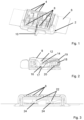
- Figure 1 shows a schematic view of a distribution valve according to a first embodiment of the present invention. It has a connection without a closable connection channel 2 and six connection channels, the connections 4 of which are shown.
- the connections 4 of the connection channels are connected to the connection without a closable connection channel 2.
- the connection channels are not shown. They are formed in a film 6 which has two film layers fastened to one another, between which the various channels and also the connection channels are located.
- the distribution valve has six individual switching elements 8 and a collective switching element 10. For reasons of clarity, only three of the connections 4 and the individual switching elements 8 are provided with a reference number.
- the individual switching elements 8 are designed as eccentric levers and are arranged in such a way that each individual switching element 8 can influence exactly one connection channel. In the embodiment shown, this is located below the respective individual switching element 8. In the embodiment shown, each connection channel can be influenced by exactly one individual switching element 8.
- the individual switching elements 8 are located in Figure 1 all in the switching position.
- the collective switching element 10 is designed as a slide. In the embodiment shown, it is set up to influence all connection channels. The collective switching element 10 is located in Figure 1 in the switching position.
- Figure 2 shows the distribution valve Figure 1 in a sectional view.
- a single switching element 8 which is designed as an eccentric lever and is designed to be pivotable about a pivot axis 12.
- the single switching element 8 has an eccentric projection 14 which is eccentric with respect to the pivot axis 12 and which, in the embodiment shown, presses on a pusher 16 of a spring 18.
- the spring 18 is preferably made of an elastic material, for example a plastic.
- the spring 18 is fixed to a base plate with a fastening end 20 that is opposite the pusher 16.
- the bent part of the spring 18 that extends between the pusher 16 and the fastening end 20 therefore acts as a spring that applies a force to the pusher 16.
- This force acts upwards, i.e.
- the individual switching element 8 is shown in its switching position, in which the eccentric projection 14 presses the pusher 16 of the spring 18 onto the connection channel (not shown) and thus closes it.
- the pusher 16 presses on a counter-pressure element, which in this case is designed as a round cord 17.
- the distribution valve has a base body which has a rear part 19. In the embodiment shown, this rear part 19 is curved and acts as a spring.
- FIG 3 shows a sectional view through the distribution valve from the Figures 1 and 2 in a different cutting direction.
- the collective switching element 10 has two ramps 22 which interact with two projections 24.
- the ramps 22 are part of the collective switching element 10 and the two projections 24 are part of the base body to which the individual switching elements 8 are attached. This is the case in the embodiment shown, but is not necessary. Since the collective switching element 10 is in its switching position, the projections 24 are pressed downwards by the ramps, i.e. towards the connection channels. In the embodiment shown, this means that the pusher 16 of the spring 18, on which the eccentric projection 14 of the individual switching element 8 presses, closes the respective connection channel.
- the rear part 19 of the base body, which acts as a spring is in Figure 3 not shown, but exerts a force on the two projections 24, which is also transmitted to the individual switching elements 8. In the embodiment shown, this force acts upwards.
- FIGs 4 to 6 correspond to the representations of the Figures 1 to 3 , whereby in the Figures 4 to 6 the collective switching element 10 is in the flow position. The individual switching elements 8 are still in their switching position. Figure 4 that the collective switching element 10 compared to Figure 1 moved to the left and thus brought into the flow position.
- FIGS 7 to 9 show the representations of the Figures 1 to 3 , whereby one of the individual switching elements 8 has been moved from the switching position to the flow position.
- the collective switching element 10 is in the switching position. This is particularly important in Figure 7 clearly visible.
- Figure 8 shows the effects of this movement of the individual switching element 8.
- the individual switching element 8 is pivoted about the pivot axis 12.
- the eccentric projection 14 is also pivoted about the pivot axis 12, so that it is no longer in contact with the pusher 16 of the spring 18. Due to the force generated by the spring 18, the pusher 16 has moved upwards. It has therefore moved away from the connection channel and is now no longer able to close the connection channel.
- connection channel is therefore always open when at least one of the switching elements influencing this connection channel, i.e. the respective individual switching element 8 or the collective switching element 10, is in its respective flow position. If both switching elements are in their switching position, the connection channel is closed; if both switching elements are in their flow position, the connection channel is open.
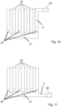
- FIGS. 10 and 11 show a schematic of a distribution valve with an inlet on which an interface 26 is arranged.
- a connection channel or another fluid line for example a hose or a valve, can be connected via this interface so that fluid can enter the distribution valve through the interface 26.
- a fluid source for example a pump
- a cushion or a chamber or another fluid reservoir can be coupled to the interface 26. Consequently, fluid, preferably air, can be introduced into the distribution valve from the outside through the interface 26.
- the interface can preferably be closed by a closure element, for example a valve, a stopper or a plug.
- the interface 26 is in the Figure 11 shown embodiment is arranged at the end of a connection without a closable connection channel 2, which accordingly has no switching area 25.
- connection channels 23 shown without an interface the Figures 10 and 11 upper end of the respective connection 4.
Landscapes
- Engineering & Computer Science (AREA)
- General Engineering & Computer Science (AREA)
- Mechanical Engineering (AREA)
- Multiple-Way Valves (AREA)
Applications Claiming Priority (1)
| Application Number | Priority Date | Filing Date | Title |
|---|---|---|---|
| DE102022130363.2A DE102022130363A1 (de) | 2022-11-16 | 2022-11-16 | Verteilventil |
Publications (1)
| Publication Number | Publication Date |
|---|---|
| EP4372255A1 true EP4372255A1 (fr) | 2024-05-22 |
Family
ID=88837308
Family Applications (1)
| Application Number | Title | Priority Date | Filing Date |
|---|---|---|---|
| EP23210086.7A Pending EP4372255A1 (fr) | 2022-11-16 | 2023-11-15 | Soupape de distribution |
Country Status (2)
| Country | Link |
|---|---|
| EP (1) | EP4372255A1 (fr) |
| DE (1) | DE102022130363A1 (fr) |
Citations (4)
| Publication number | Priority date | Publication date | Assignee | Title |
|---|---|---|---|---|
| US20150233485A1 (en) * | 2012-10-19 | 2015-08-20 | Mei-Li Cheng | Valve Positioning Structure |
| US20150354192A1 (en) * | 2013-03-11 | 2015-12-10 | Neoperl Gmbh | Hand-held shower holding device |
| CN109838588A (zh) * | 2017-11-24 | 2019-06-04 | 厦门松霖科技股份有限公司 | 多按钮水路切换机构 |
| WO2022122512A1 (fr) * | 2020-12-07 | 2022-06-16 | Otto Bock Mobility Solutions Gmbh | Procédé de fabrication d'un coussin et coussin |
Family Cites Families (5)
| Publication number | Priority date | Publication date | Assignee | Title |
|---|---|---|---|---|
| GB1276243A (en) * | 1970-01-14 | 1972-06-01 | Drallim Ltd | Improvements relating to fluid flow control valves |
| GB1365032A (en) * | 1972-02-29 | 1974-08-29 | Haamann Hebe Und Transport Tec | Fluidoperable lifting device |
| US5658050A (en) * | 1996-01-11 | 1997-08-19 | Milsco Manufacturing Company | Vehicle seat with inflatable bladder |
| US8794266B1 (en) * | 2011-10-18 | 2014-08-05 | Humphrey Products Company | Cam actuated valve assembly with manual and electric activation |
| DE102017002784A1 (de) * | 2017-03-23 | 2018-09-27 | Scheuerle Fahrzeugfabrik Gmbh | Steuereinheit für eine Steuerungsvorrichtung für ein Schwerlast-Fahrzeug, insbesondere für einen Schwanenhals, eine Hubanordnung oder eine Lenkanordnung eines Schwerlast-Fahrzeugs, sowie eine derartige Steuerungsvorrichtung |
-
2022
- 2022-11-16 DE DE102022130363.2A patent/DE102022130363A1/de active Pending
-
2023
- 2023-11-15 EP EP23210086.7A patent/EP4372255A1/fr active Pending
Patent Citations (4)
| Publication number | Priority date | Publication date | Assignee | Title |
|---|---|---|---|---|
| US20150233485A1 (en) * | 2012-10-19 | 2015-08-20 | Mei-Li Cheng | Valve Positioning Structure |
| US20150354192A1 (en) * | 2013-03-11 | 2015-12-10 | Neoperl Gmbh | Hand-held shower holding device |
| CN109838588A (zh) * | 2017-11-24 | 2019-06-04 | 厦门松霖科技股份有限公司 | 多按钮水路切换机构 |
| WO2022122512A1 (fr) * | 2020-12-07 | 2022-06-16 | Otto Bock Mobility Solutions Gmbh | Procédé de fabrication d'un coussin et coussin |
Also Published As
| Publication number | Publication date |
|---|---|
| DE102022130363A1 (de) | 2024-05-16 |
Similar Documents
| Publication | Publication Date | Title |
|---|---|---|
| DE69218213T2 (de) | Sammelleitung mit mehreren ventilen für ein medikamenten-infusionssystem | |
| DE69323739T2 (de) | Arzneimittel infusionsvorrichtung | |
| DE69731196T2 (de) | Ballonkatheter mit ventil mit niedrigem profil | |
| DE69408288T2 (de) | Flüssigkeitsverteiler mit Elektromagnetventilen | |
| EP2421579B1 (fr) | Ensemble soupape, garniture de soupape, dispositif fonctionnel externe, appareil de traitement ainsi que procédés | |
| DE68918437T2 (de) | Kontinuierliche Injektionsvorrichtung für flüssige Medikamente. | |
| DE2363721A1 (de) | Transporteinrichtung | |
| EP0865265A2 (fr) | Dispositif pour reguler la temperature de parties de cutanees du corps humain | |
| DE3112533A1 (de) | Vorrichtung zum steuern der zufuhr einer intravenoes zu verabfolgenden fluessigkeit zum patienten | |
| AT412204B (de) | Entleervorrichtung für abgefülltes wasser | |
| DE102009060533A1 (de) | Implantierbares Shuntsystem | |
| DE69212303T2 (de) | Ventil | |
| DE69831760T2 (de) | Ultraschall-Schweissbacke | |
| DE2046398A1 (de) | Zusammenquetschbare Rohre | |
| DE3801674A1 (de) | Geraet zum auftrag von fluessigkeit | |
| DE102009024469A1 (de) | Ventilvorrichtung, Ventileinsatz, externe Funktionseinrichtung, Behandlungsvorrichtung sowie Verfahren | |
| EP2089084B1 (fr) | Garniture pour seringue ou ampoule | |
| DE60020826T2 (de) | Gerät zur reduzierung von fluidrücklauf durch ein medizinisches ventil | |
| DE69736837T2 (de) | Anschlussventil für eine magenpumpe | |
| EP2873465A1 (fr) | Piston pour distribuer un fluide d'une cartouche | |
| EP4372255A1 (fr) | Soupape de distribution | |
| DE69630047T2 (de) | Füllsystem für primäre und sekundäre Produkte | |
| EP0729312B1 (fr) | Dispositif pour preparer en discontinu des pates alimentaires en portions | |
| EP3140242B1 (fr) | Dispositif de remplissage | |
| EP1309403A1 (fr) | Bloc de commutation comportant au moins un recipient de reaction integre ou associe |
Legal Events
| Date | Code | Title | Description |
|---|---|---|---|
| PUAI | Public reference made under article 153(3) epc to a published international application that has entered the european phase |
Free format text: ORIGINAL CODE: 0009012 |
|
| STAA | Information on the status of an ep patent application or granted ep patent |
Free format text: STATUS: THE APPLICATION HAS BEEN PUBLISHED |
|
| AK | Designated contracting states |
Kind code of ref document: A1 Designated state(s): AL AT BE BG CH CY CZ DE DK EE ES FI FR GB GR HR HU IE IS IT LI LT LU LV MC ME MK MT NL NO PL PT RO RS SE SI SK SM TR |
|
| STAA | Information on the status of an ep patent application or granted ep patent |
Free format text: STATUS: REQUEST FOR EXAMINATION WAS MADE |
|
| 17P | Request for examination filed |
Effective date: 20241119 |
|
| RBV | Designated contracting states (corrected) |
Designated state(s): AL AT BE BG CH CY CZ DE DK EE ES FI FR GB GR HR HU IE IS IT LI LT LU LV MC ME MK MT NL NO PL PT RO RS SE SI SK SM TR |
|
| STAA | Information on the status of an ep patent application or granted ep patent |
Free format text: STATUS: EXAMINATION IS IN PROGRESS |
|
| 17Q | First examination report despatched |
Effective date: 20260105 |