EP4372851A2 - Verfahren zur herstellung einer verbindung für einen stapel einer elektrochemischen vorrichtung mittels spark-plasma-sintern - Google Patents
Verfahren zur herstellung einer verbindung für einen stapel einer elektrochemischen vorrichtung mittels spark-plasma-sintern Download PDFInfo
- Publication number
- EP4372851A2 EP4372851A2 EP23194167.5A EP23194167A EP4372851A2 EP 4372851 A2 EP4372851 A2 EP 4372851A2 EP 23194167 A EP23194167 A EP 23194167A EP 4372851 A2 EP4372851 A2 EP 4372851A2
- Authority
- EP
- European Patent Office
- Prior art keywords
- interconnect
- powder
- fuel
- sps
- protective
- Prior art date
- Legal status (The legal status is an assumption and is not a legal conclusion. Google has not performed a legal analysis and makes no representation as to the accuracy of the status listed.)
- Pending
Links
- 238000000034 method Methods 0.000 title claims abstract description 92
- 238000002490 spark plasma sintering Methods 0.000 title claims abstract description 66
- 239000000843 powder Substances 0.000 claims abstract description 119
- XEEYBQQBJWHFJM-UHFFFAOYSA-N Iron Chemical compound [Fe] XEEYBQQBJWHFJM-UHFFFAOYSA-N 0.000 claims abstract description 103
- 239000000463 material Substances 0.000 claims abstract description 93
- 229910052742 iron Inorganic materials 0.000 claims abstract description 49
- 239000011651 chromium Substances 0.000 claims abstract description 31
- 229910052804 chromium Inorganic materials 0.000 claims abstract description 24
- VYZAMTAEIAYCRO-UHFFFAOYSA-N Chromium Chemical compound [Cr] VYZAMTAEIAYCRO-UHFFFAOYSA-N 0.000 claims abstract description 23
- 239000000446 fuel Substances 0.000 claims description 227
- 239000010410 layer Substances 0.000 claims description 83
- 230000001681 protective effect Effects 0.000 claims description 35
- 239000002131 composite material Substances 0.000 claims description 21
- 239000007787 solid Substances 0.000 claims description 13
- 238000010438 heat treatment Methods 0.000 claims description 9
- 229910044991 metal oxide Inorganic materials 0.000 claims description 8
- 150000004706 metal oxides Chemical class 0.000 claims description 8
- 239000000314 lubricant Substances 0.000 claims description 7
- 239000011241 protective layer Substances 0.000 claims description 7
- 229910052596 spinel Inorganic materials 0.000 claims description 7
- 239000011029 spinel Substances 0.000 claims description 7
- OKTJSMMVPCPJKN-UHFFFAOYSA-N Carbon Chemical compound [C] OKTJSMMVPCPJKN-UHFFFAOYSA-N 0.000 claims description 5
- 229910002804 graphite Inorganic materials 0.000 claims description 5
- 239000010439 graphite Substances 0.000 claims description 5
- 239000004489 contact powder Substances 0.000 claims description 4
- 239000011888 foil Substances 0.000 claims description 4
- 230000008569 process Effects 0.000 description 33
- 239000011253 protective coating Substances 0.000 description 29
- PXHVJJICTQNCMI-UHFFFAOYSA-N Nickel Chemical compound [Ni] PXHVJJICTQNCMI-UHFFFAOYSA-N 0.000 description 26
- 238000000576 coating method Methods 0.000 description 21
- 238000005245 sintering Methods 0.000 description 18
- 229910002075 lanthanum strontium manganite Inorganic materials 0.000 description 17
- 239000011248 coating agent Substances 0.000 description 15
- 230000015572 biosynthetic process Effects 0.000 description 13
- 239000011521 glass Substances 0.000 description 13
- 229910000599 Cr alloy Inorganic materials 0.000 description 11
- 229910019589 Cr—Fe Inorganic materials 0.000 description 10
- 239000000788 chromium alloy Substances 0.000 description 10
- 229910045601 alloy Inorganic materials 0.000 description 9
- 239000000956 alloy Substances 0.000 description 9
- 229910052759 nickel Inorganic materials 0.000 description 9
- UQSXHKLRYXJYBZ-UHFFFAOYSA-N Iron oxide Chemical compound [Fe]=O UQSXHKLRYXJYBZ-UHFFFAOYSA-N 0.000 description 8
- 239000012298 atmosphere Substances 0.000 description 8
- 238000005056 compaction Methods 0.000 description 8
- 239000003792 electrolyte Substances 0.000 description 8
- 238000004519 manufacturing process Methods 0.000 description 8
- 238000001000 micrograph Methods 0.000 description 8
- 239000000203 mixture Substances 0.000 description 8
- 230000002093 peripheral effect Effects 0.000 description 8
- 238000009792 diffusion process Methods 0.000 description 7
- 230000003647 oxidation Effects 0.000 description 7
- 238000007254 oxidation reaction Methods 0.000 description 7
- 239000002245 particle Substances 0.000 description 6
- 238000003825 pressing Methods 0.000 description 6
- WGLPBDUCMAPZCE-UHFFFAOYSA-N Trioxochromium Chemical compound O=[Cr](=O)=O WGLPBDUCMAPZCE-UHFFFAOYSA-N 0.000 description 5
- UPHIPHFJVNKLMR-UHFFFAOYSA-N chromium iron Chemical compound [Cr].[Fe] UPHIPHFJVNKLMR-UHFFFAOYSA-N 0.000 description 5
- 229910000423 chromium oxide Inorganic materials 0.000 description 5
- 210000003739 neck Anatomy 0.000 description 5
- 229910000640 Fe alloy Inorganic materials 0.000 description 4
- QVGXLLKOCUKJST-UHFFFAOYSA-N atomic oxygen Chemical compound [O] QVGXLLKOCUKJST-UHFFFAOYSA-N 0.000 description 4
- 150000001768 cations Chemical class 0.000 description 4
- 239000000919 ceramic Substances 0.000 description 4
- 230000006835 compression Effects 0.000 description 4
- 238000007906 compression Methods 0.000 description 4
- 239000004020 conductor Substances 0.000 description 4
- 238000000151 deposition Methods 0.000 description 4
- 238000009826 distribution Methods 0.000 description 4
- 239000011572 manganese Substances 0.000 description 4
- 239000007800 oxidant agent Substances 0.000 description 4
- 230000001590 oxidative effect Effects 0.000 description 4
- 239000001301 oxygen Substances 0.000 description 4
- 229910052760 oxygen Inorganic materials 0.000 description 4
- 229910002076 stabilized zirconia Inorganic materials 0.000 description 4
- 239000012300 argon atmosphere Substances 0.000 description 3
- 239000011230 binding agent Substances 0.000 description 3
- CETPSERCERDGAM-UHFFFAOYSA-N ceric oxide Chemical compound O=[Ce]=O CETPSERCERDGAM-UHFFFAOYSA-N 0.000 description 3
- 229910000422 cerium(IV) oxide Inorganic materials 0.000 description 3
- 229910017052 cobalt Inorganic materials 0.000 description 3
- 239000010941 cobalt Substances 0.000 description 3
- GUTLYIVDDKVIGB-UHFFFAOYSA-N cobalt atom Chemical compound [Co] GUTLYIVDDKVIGB-UHFFFAOYSA-N 0.000 description 3
- 239000007789 gas Substances 0.000 description 3
- 229910052748 manganese Inorganic materials 0.000 description 3
- 238000005259 measurement Methods 0.000 description 3
- 229910052751 metal Inorganic materials 0.000 description 3
- 239000002184 metal Substances 0.000 description 3
- 229910052727 yttrium Inorganic materials 0.000 description 3
- RUDFQVOCFDJEEF-UHFFFAOYSA-N yttrium(III) oxide Inorganic materials [O-2].[O-2].[O-2].[Y+3].[Y+3] RUDFQVOCFDJEEF-UHFFFAOYSA-N 0.000 description 3
- XKRFYHLGVUSROY-UHFFFAOYSA-N Argon Chemical compound [Ar] XKRFYHLGVUSROY-UHFFFAOYSA-N 0.000 description 2
- IJGRMHOSHXDMSA-UHFFFAOYSA-N Atomic nitrogen Chemical compound N#N IJGRMHOSHXDMSA-UHFFFAOYSA-N 0.000 description 2
- 239000004215 Carbon black (E152) Substances 0.000 description 2
- 229910002467 CrFe Inorganic materials 0.000 description 2
- 229910017060 Fe Cr Inorganic materials 0.000 description 2
- 229910002544 Fe-Cr Inorganic materials 0.000 description 2
- UFHFLCQGNIYNRP-UHFFFAOYSA-N Hydrogen Chemical compound [H][H] UFHFLCQGNIYNRP-UHFFFAOYSA-N 0.000 description 2
- PWHULOQIROXLJO-UHFFFAOYSA-N Manganese Chemical compound [Mn] PWHULOQIROXLJO-UHFFFAOYSA-N 0.000 description 2
- 229910003164 Mn2CoO4 Inorganic materials 0.000 description 2
- 241000968352 Scandia <hydrozoan> Species 0.000 description 2
- FVROQKXVYSIMQV-UHFFFAOYSA-N [Sr+2].[La+3].[O-][Mn]([O-])=O Chemical compound [Sr+2].[La+3].[O-][Mn]([O-])=O FVROQKXVYSIMQV-UHFFFAOYSA-N 0.000 description 2
- 150000001450 anions Chemical class 0.000 description 2
- 238000002167 anodic stripping potentiometry Methods 0.000 description 2
- 206010003664 atrial septal defect Diseases 0.000 description 2
- 238000005422 blasting Methods 0.000 description 2
- 229910052796 boron Inorganic materials 0.000 description 2
- 238000007796 conventional method Methods 0.000 description 2
- 238000000280 densification Methods 0.000 description 2
- 238000013461 design Methods 0.000 description 2
- QDOXWKRWXJOMAK-UHFFFAOYSA-N dichromium trioxide Chemical compound O=[Cr]O[Cr]=O QDOXWKRWXJOMAK-UHFFFAOYSA-N 0.000 description 2
- 238000002149 energy-dispersive X-ray emission spectroscopy Methods 0.000 description 2
- -1 gadolinia Chemical compound 0.000 description 2
- CMIHHWBVHJVIGI-UHFFFAOYSA-N gadolinium(iii) oxide Chemical compound [O-2].[O-2].[O-2].[Gd+3].[Gd+3] CMIHHWBVHJVIGI-UHFFFAOYSA-N 0.000 description 2
- 230000009477 glass transition Effects 0.000 description 2
- 235000003642 hunger Nutrition 0.000 description 2
- 229930195733 hydrocarbon Natural products 0.000 description 2
- 150000002430 hydrocarbons Chemical class 0.000 description 2
- 239000001257 hydrogen Substances 0.000 description 2
- 229910052739 hydrogen Inorganic materials 0.000 description 2
- WSHADMOVDWUXEY-UHFFFAOYSA-N manganese oxocobalt Chemical compound [Co]=O.[Mn] WSHADMOVDWUXEY-UHFFFAOYSA-N 0.000 description 2
- 229910001092 metal group alloy Inorganic materials 0.000 description 2
- 150000002739 metals Chemical class 0.000 description 2
- 238000012986 modification Methods 0.000 description 2
- 230000004048 modification Effects 0.000 description 2
- 229910000480 nickel oxide Inorganic materials 0.000 description 2
- GNRSAWUEBMWBQH-UHFFFAOYSA-N oxonickel Chemical compound [Ni]=O GNRSAWUEBMWBQH-UHFFFAOYSA-N 0.000 description 2
- HJGMWXTVGKLUAQ-UHFFFAOYSA-N oxygen(2-);scandium(3+) Chemical compound [O-2].[O-2].[O-2].[Sc+3].[Sc+3] HJGMWXTVGKLUAQ-UHFFFAOYSA-N 0.000 description 2
- 238000007750 plasma spraying Methods 0.000 description 2
- 239000011148 porous material Substances 0.000 description 2
- 238000004663 powder metallurgy Methods 0.000 description 2
- 238000005507 spraying Methods 0.000 description 2
- 230000037351 starvation Effects 0.000 description 2
- 229910001233 yttria-stabilized zirconia Inorganic materials 0.000 description 2
- VWQVUPCCIRVNHF-UHFFFAOYSA-N yttrium atom Chemical compound [Y] VWQVUPCCIRVNHF-UHFFFAOYSA-N 0.000 description 2
- 229910000531 Co alloy Inorganic materials 0.000 description 1
- 229910003166 Mn1.5Co1.5O4 Inorganic materials 0.000 description 1
- 229910003168 MnCo2O4 Inorganic materials 0.000 description 1
- 229910000990 Ni alloy Inorganic materials 0.000 description 1
- PMTBMZQLTAVEGP-UHFFFAOYSA-N [O-2].[Cr+3].[Co+2].[Mn+2] Chemical compound [O-2].[Cr+3].[Co+2].[Mn+2] PMTBMZQLTAVEGP-UHFFFAOYSA-N 0.000 description 1
- 229910052782 aluminium Inorganic materials 0.000 description 1
- 229910000323 aluminium silicate Inorganic materials 0.000 description 1
- 238000013459 approach Methods 0.000 description 1
- 229910052786 argon Inorganic materials 0.000 description 1
- 238000000429 assembly Methods 0.000 description 1
- 230000000712 assembly Effects 0.000 description 1
- 229910052788 barium Inorganic materials 0.000 description 1
- 229910052791 calcium Inorganic materials 0.000 description 1
- 230000015556 catabolic process Effects 0.000 description 1
- 230000022131 cell cycle Effects 0.000 description 1
- 229910021525 ceramic electrolyte Inorganic materials 0.000 description 1
- 229910010293 ceramic material Inorganic materials 0.000 description 1
- 239000011195 cermet Substances 0.000 description 1
- IUWCPXJTIPQGTE-UHFFFAOYSA-N chromium cobalt Chemical compound [Cr].[Co].[Co].[Co] IUWCPXJTIPQGTE-UHFFFAOYSA-N 0.000 description 1
- 229910001430 chromium ion Inorganic materials 0.000 description 1
- UBEWDCMIDFGDOO-UHFFFAOYSA-N cobalt(II,III) oxide Inorganic materials [O-2].[O-2].[O-2].[O-2].[Co+2].[Co+3].[Co+3] UBEWDCMIDFGDOO-UHFFFAOYSA-N 0.000 description 1
- 239000000356 contaminant Substances 0.000 description 1
- 238000004320 controlled atmosphere Methods 0.000 description 1
- 230000003247 decreasing effect Effects 0.000 description 1
- 238000006731 degradation reaction Methods 0.000 description 1
- 238000005137 deposition process Methods 0.000 description 1
- HNPSIPDUKPIQMN-UHFFFAOYSA-N dioxosilane;oxo(oxoalumanyloxy)alumane Chemical compound O=[Si]=O.O=[Al]O[Al]=O HNPSIPDUKPIQMN-UHFFFAOYSA-N 0.000 description 1
- 238000005485 electric heating Methods 0.000 description 1
- 238000003487 electrochemical reaction Methods 0.000 description 1
- 230000008030 elimination Effects 0.000 description 1
- 238000003379 elimination reaction Methods 0.000 description 1
- 239000012530 fluid Substances 0.000 description 1
- 230000004927 fusion Effects 0.000 description 1
- 239000005431 greenhouse gas Substances 0.000 description 1
- 239000001307 helium Substances 0.000 description 1
- 229910052734 helium Inorganic materials 0.000 description 1
- SWQJXJOGLNCZEY-UHFFFAOYSA-N helium atom Chemical compound [He] SWQJXJOGLNCZEY-UHFFFAOYSA-N 0.000 description 1
- 239000012535 impurity Substances 0.000 description 1
- 238000005304 joining Methods 0.000 description 1
- 229910052746 lanthanum Inorganic materials 0.000 description 1
- 229910021318 lanthanum strontium oxide Inorganic materials 0.000 description 1
- 229910052749 magnesium Inorganic materials 0.000 description 1
- AMWRITDGCCNYAT-UHFFFAOYSA-L manganese oxide Inorganic materials [Mn].O[Mn]=O.O[Mn]=O AMWRITDGCCNYAT-UHFFFAOYSA-L 0.000 description 1
- WPBNNNQJVZRUHP-UHFFFAOYSA-L manganese(2+);methyl n-[[2-(methoxycarbonylcarbamothioylamino)phenyl]carbamothioyl]carbamate;n-[2-(sulfidocarbothioylamino)ethyl]carbamodithioate Chemical compound [Mn+2].[S-]C(=S)NCCNC([S-])=S.COC(=O)NC(=S)NC1=CC=CC=C1NC(=S)NC(=O)OC WPBNNNQJVZRUHP-UHFFFAOYSA-L 0.000 description 1
- 239000007769 metal material Substances 0.000 description 1
- 229910052757 nitrogen Inorganic materials 0.000 description 1
- 230000035699 permeability Effects 0.000 description 1
- 239000004033 plastic Substances 0.000 description 1
- 238000007639 printing Methods 0.000 description 1
- 238000004064 recycling Methods 0.000 description 1
- 230000009467 reduction Effects 0.000 description 1
- FKTOIHSPIPYAPE-UHFFFAOYSA-N samarium(iii) oxide Chemical compound [O-2].[O-2].[O-2].[Sm+3].[Sm+3] FKTOIHSPIPYAPE-UHFFFAOYSA-N 0.000 description 1
- 239000004576 sand Substances 0.000 description 1
- 238000007650 screen-printing Methods 0.000 description 1
- 235000008113 selfheal Nutrition 0.000 description 1
- 229910052710 silicon Inorganic materials 0.000 description 1
- 229910052566 spinel group Inorganic materials 0.000 description 1
- 238000009718 spray deposition Methods 0.000 description 1
- 229910052712 strontium Inorganic materials 0.000 description 1
- IGPAMRAHTMKVDN-UHFFFAOYSA-N strontium dioxido(dioxo)manganese lanthanum(3+) Chemical compound [Sr+2].[La+3].[O-][Mn]([O-])(=O)=O IGPAMRAHTMKVDN-UHFFFAOYSA-N 0.000 description 1
- ZXMVMNJYECENGY-UHFFFAOYSA-N strontium lanthanum(3+) oxygen(2-) Chemical compound [O-2].[Sr+2].[La+3] ZXMVMNJYECENGY-UHFFFAOYSA-N 0.000 description 1
- 238000005382 thermal cycling Methods 0.000 description 1
- 229910052723 transition metal Inorganic materials 0.000 description 1
- 150000003624 transition metals Chemical class 0.000 description 1
- XLYOFNOQVPJJNP-UHFFFAOYSA-N water Chemical compound O XLYOFNOQVPJJNP-UHFFFAOYSA-N 0.000 description 1
Images






Classifications
-
- H—ELECTRICITY
- H01—ELECTRIC ELEMENTS
- H01M—PROCESSES OR MEANS, e.g. BATTERIES, FOR THE DIRECT CONVERSION OF CHEMICAL ENERGY INTO ELECTRICAL ENERGY
- H01M8/00—Fuel cells; Manufacture thereof
- H01M8/02—Details
- H01M8/0202—Collectors; Separators, e.g. bipolar separators; Interconnectors
- H01M8/023—Porous and characterised by the material
- H01M8/0232—Metals or alloys
-
- H—ELECTRICITY
- H01—ELECTRIC ELEMENTS
- H01M—PROCESSES OR MEANS, e.g. BATTERIES, FOR THE DIRECT CONVERSION OF CHEMICAL ENERGY INTO ELECTRICAL ENERGY
- H01M8/00—Fuel cells; Manufacture thereof
- H01M8/02—Details
- H01M8/0202—Collectors; Separators, e.g. bipolar separators; Interconnectors
- H01M8/0204—Non-porous and characterised by the material
- H01M8/0215—Glass; Ceramic materials
- H01M8/0217—Complex oxides, optionally doped, of the type AMO3, A being an alkaline earth metal or rare earth metal and M being a metal, e.g. perovskites
-
- B—PERFORMING OPERATIONS; TRANSPORTING
- B22—CASTING; POWDER METALLURGY
- B22F—WORKING METALLIC POWDER; MANUFACTURE OF ARTICLES FROM METALLIC POWDER; MAKING METALLIC POWDER; APPARATUS OR DEVICES SPECIALLY ADAPTED FOR METALLIC POWDER
- B22F1/00—Metallic powder; Treatment of metallic powder, e.g. to facilitate working or to improve properties
- B22F1/09—Mixtures of metallic powders
-
- B—PERFORMING OPERATIONS; TRANSPORTING
- B22—CASTING; POWDER METALLURGY
- B22F—WORKING METALLIC POWDER; MANUFACTURE OF ARTICLES FROM METALLIC POWDER; MAKING METALLIC POWDER; APPARATUS OR DEVICES SPECIALLY ADAPTED FOR METALLIC POWDER
- B22F3/00—Manufacture of workpieces or articles from metallic powder characterised by the manner of compacting or sintering; Apparatus specially adapted therefor ; Presses and furnaces
- B22F3/10—Sintering only
- B22F3/105—Sintering only by using electric current other than for infrared radiant energy, laser radiation or plasma ; by ultrasonic bonding
-
- B—PERFORMING OPERATIONS; TRANSPORTING
- B22—CASTING; POWDER METALLURGY
- B22F—WORKING METALLIC POWDER; MANUFACTURE OF ARTICLES FROM METALLIC POWDER; MAKING METALLIC POWDER; APPARATUS OR DEVICES SPECIALLY ADAPTED FOR METALLIC POWDER
- B22F7/00—Manufacture of composite layers, workpieces, or articles, comprising metallic powder, by sintering the powder, with or without compacting wherein at least one part is obtained by sintering or compression
- B22F7/06—Manufacture of composite layers, workpieces, or articles, comprising metallic powder, by sintering the powder, with or without compacting wherein at least one part is obtained by sintering or compression of composite workpieces or articles from parts, e.g. to form tipped tools
- B22F7/062—Manufacture of composite layers, workpieces, or articles, comprising metallic powder, by sintering the powder, with or without compacting wherein at least one part is obtained by sintering or compression of composite workpieces or articles from parts, e.g. to form tipped tools involving the connection or repairing of preformed parts
- B22F7/064—Manufacture of composite layers, workpieces, or articles, comprising metallic powder, by sintering the powder, with or without compacting wherein at least one part is obtained by sintering or compression of composite workpieces or articles from parts, e.g. to form tipped tools involving the connection or repairing of preformed parts using an intermediate powder layer
-
- C—CHEMISTRY; METALLURGY
- C22—METALLURGY; FERROUS OR NON-FERROUS ALLOYS; TREATMENT OF ALLOYS OR NON-FERROUS METALS
- C22C—ALLOYS
- C22C38/00—Ferrous alloys, e.g. steel alloys
- C22C38/18—Ferrous alloys, e.g. steel alloys containing chromium
-
- C—CHEMISTRY; METALLURGY
- C25—ELECTROLYTIC OR ELECTROPHORETIC PROCESSES; APPARATUS THEREFOR
- C25B—ELECTROLYTIC OR ELECTROPHORETIC PROCESSES FOR THE PRODUCTION OF COMPOUNDS OR NON-METALS; APPARATUS THEREFOR
- C25B9/00—Cells or assemblies of cells; Constructional parts of cells; Assemblies of constructional parts, e.g. electrode-diaphragm assemblies; Process-related cell features
- C25B9/60—Constructional parts of cells
- C25B9/65—Means for supplying current; Electrode connections; Electric inter-cell connections
-
- C—CHEMISTRY; METALLURGY
- C25—ELECTROLYTIC OR ELECTROPHORETIC PROCESSES; APPARATUS THEREFOR
- C25B—ELECTROLYTIC OR ELECTROPHORETIC PROCESSES FOR THE PRODUCTION OF COMPOUNDS OR NON-METALS; APPARATUS THEREFOR
- C25B9/00—Cells or assemblies of cells; Constructional parts of cells; Assemblies of constructional parts, e.g. electrode-diaphragm assemblies; Process-related cell features
- C25B9/70—Assemblies comprising two or more cells
- C25B9/73—Assemblies comprising two or more cells of the filter-press type
- C25B9/77—Assemblies comprising two or more cells of the filter-press type having diaphragms
-
- H—ELECTRICITY
- H01—ELECTRIC ELEMENTS
- H01M—PROCESSES OR MEANS, e.g. BATTERIES, FOR THE DIRECT CONVERSION OF CHEMICAL ENERGY INTO ELECTRICAL ENERGY
- H01M8/00—Fuel cells; Manufacture thereof
- H01M8/02—Details
- H01M8/0202—Collectors; Separators, e.g. bipolar separators; Interconnectors
- H01M8/0204—Non-porous and characterised by the material
- H01M8/0206—Metals or alloys
- H01M8/0208—Alloys
- H01M8/021—Alloys based on iron
-
- H—ELECTRICITY
- H01—ELECTRIC ELEMENTS
- H01M—PROCESSES OR MEANS, e.g. BATTERIES, FOR THE DIRECT CONVERSION OF CHEMICAL ENERGY INTO ELECTRICAL ENERGY
- H01M8/00—Fuel cells; Manufacture thereof
- H01M8/02—Details
- H01M8/0202—Collectors; Separators, e.g. bipolar separators; Interconnectors
- H01M8/0204—Non-porous and characterised by the material
- H01M8/0223—Composites
- H01M8/0228—Composites in the form of layered or coated products
-
- H—ELECTRICITY
- H01—ELECTRIC ELEMENTS
- H01M—PROCESSES OR MEANS, e.g. BATTERIES, FOR THE DIRECT CONVERSION OF CHEMICAL ENERGY INTO ELECTRICAL ENERGY
- H01M8/00—Fuel cells; Manufacture thereof
- H01M8/02—Details
- H01M8/0202—Collectors; Separators, e.g. bipolar separators; Interconnectors
- H01M8/023—Porous and characterised by the material
- H01M8/0241—Composites
- H01M8/0245—Composites in the form of layered or coated products
-
- H—ELECTRICITY
- H01—ELECTRIC ELEMENTS
- H01M—PROCESSES OR MEANS, e.g. BATTERIES, FOR THE DIRECT CONVERSION OF CHEMICAL ENERGY INTO ELECTRICAL ENERGY
- H01M8/00—Fuel cells; Manufacture thereof
- H01M8/10—Fuel cells with solid electrolytes
- H01M8/12—Fuel cells with solid electrolytes operating at high temperature, e.g. with stabilised ZrO2 electrolyte
- H01M8/124—Fuel cells with solid electrolytes operating at high temperature, e.g. with stabilised ZrO2 electrolyte characterised by the process of manufacturing or by the material of the electrolyte
- H01M8/1246—Fuel cells with solid electrolytes operating at high temperature, e.g. with stabilised ZrO2 electrolyte characterised by the process of manufacturing or by the material of the electrolyte the electrolyte consisting of oxides
-
- B—PERFORMING OPERATIONS; TRANSPORTING
- B22—CASTING; POWDER METALLURGY
- B22F—WORKING METALLIC POWDER; MANUFACTURE OF ARTICLES FROM METALLIC POWDER; MAKING METALLIC POWDER; APPARATUS OR DEVICES SPECIALLY ADAPTED FOR METALLIC POWDER
- B22F3/00—Manufacture of workpieces or articles from metallic powder characterised by the manner of compacting or sintering; Apparatus specially adapted therefor ; Presses and furnaces
- B22F3/10—Sintering only
- B22F3/105—Sintering only by using electric current other than for infrared radiant energy, laser radiation or plasma ; by ultrasonic bonding
- B22F2003/1051—Sintering only by using electric current other than for infrared radiant energy, laser radiation or plasma ; by ultrasonic bonding by electric discharge
-
- B—PERFORMING OPERATIONS; TRANSPORTING
- B22—CASTING; POWDER METALLURGY
- B22F—WORKING METALLIC POWDER; MANUFACTURE OF ARTICLES FROM METALLIC POWDER; MAKING METALLIC POWDER; APPARATUS OR DEVICES SPECIALLY ADAPTED FOR METALLIC POWDER
- B22F2202/00—Treatment under specific physical conditions
- B22F2202/13—Use of plasma
-
- B—PERFORMING OPERATIONS; TRANSPORTING
- B22—CASTING; POWDER METALLURGY
- B22F—WORKING METALLIC POWDER; MANUFACTURE OF ARTICLES FROM METALLIC POWDER; MAKING METALLIC POWDER; APPARATUS OR DEVICES SPECIALLY ADAPTED FOR METALLIC POWDER
- B22F2998/00—Supplementary information concerning processes or compositions relating to powder metallurgy
- B22F2998/10—Processes characterised by the sequence of their steps
-
- B—PERFORMING OPERATIONS; TRANSPORTING
- B22—CASTING; POWDER METALLURGY
- B22F—WORKING METALLIC POWDER; MANUFACTURE OF ARTICLES FROM METALLIC POWDER; MAKING METALLIC POWDER; APPARATUS OR DEVICES SPECIALLY ADAPTED FOR METALLIC POWDER
- B22F2999/00—Aspects linked to processes or compositions used in powder metallurgy
-
- H—ELECTRICITY
- H01—ELECTRIC ELEMENTS
- H01M—PROCESSES OR MEANS, e.g. BATTERIES, FOR THE DIRECT CONVERSION OF CHEMICAL ENERGY INTO ELECTRICAL ENERGY
- H01M8/00—Fuel cells; Manufacture thereof
- H01M8/10—Fuel cells with solid electrolytes
- H01M8/12—Fuel cells with solid electrolytes operating at high temperature, e.g. with stabilised ZrO2 electrolyte
- H01M2008/1293—Fuel cells with solid oxide electrolytes
-
- Y—GENERAL TAGGING OF NEW TECHNOLOGICAL DEVELOPMENTS; GENERAL TAGGING OF CROSS-SECTIONAL TECHNOLOGIES SPANNING OVER SEVERAL SECTIONS OF THE IPC; TECHNICAL SUBJECTS COVERED BY FORMER USPC CROSS-REFERENCE ART COLLECTIONS [XRACs] AND DIGESTS
- Y02—TECHNOLOGIES OR APPLICATIONS FOR MITIGATION OR ADAPTATION AGAINST CLIMATE CHANGE
- Y02E—REDUCTION OF GREENHOUSE GAS [GHG] EMISSIONS, RELATED TO ENERGY GENERATION, TRANSMISSION OR DISTRIBUTION
- Y02E60/00—Enabling technologies; Technologies with a potential or indirect contribution to GHG emissions mitigation
- Y02E60/30—Hydrogen technology
- Y02E60/50—Fuel cells
Definitions
- the present embodiments are directed to fuel cell and electrolyzer interconnect manufacturing methods, specifically to methods of forming interconnects using spark plasma sintering (SPS).
- SPS spark plasma sintering
- a typical solid oxide fuel cell stack includes multiple fuel cells separated by metallic interconnects (IC) which provide both electrical connection between adjacent cells in the stack and channels for delivery and removal of fuel and oxidant.
- the metallic interconnects are commonly composed of a Cr based alloy such as an alloy known as CrFe which has a composition of 95wt% Cr-5wt% Fe, or Cr-Fe-Y having a 94wt% Cr-5wt% Fe-1wt%Y composition.
- the CrFe and CrFeY alloys retain their strength and are dimensionally stable at typical solid oxide fuel cell (SOFC) operating conditions, e.g. 700-900C in both air and wet fuel atmospheres.
- SOFC solid oxide fuel cell
- a method of forming an interconnect for an electrochemical device stack includes loading a die with an interconnect material comprising an interconnect body powder comprising chromium and iron, and spark plasma sintering (SPS) the interconnect material to form a body of the interconnect.
- SPS spark plasma sintering
- Ranges can be expressed herein as from “about” one particular value, and/or to "about” another particular value. When such a range is expressed, examples include from the one particular value and/or to the other particular value. Similarly, when values are expressed as approximations, by use of the antecedent “about” or “substantially” it will be understood that the particular value forms another aspect. In some embodiments, a value of "about X” may include values of +/- 1% X. It will be further understood that the endpoints of each of the ranges are significant both in relation to the other endpoint, and independently of the other endpoint.
- FIG. 1A is a perspective view of a conventional fuel cell column 30
- FIG. 1B is a perspective view of one counter-flow solid oxide fuel cell (SOFC) stack 20 included in the column 30 of FIG. 1A
- FIG. 1C is a side cross-sectional view of a portion of the stack 20 of FIG. 1B .
- SOFC solid oxide fuel cell
- the column 30 may include one or more stacks 20, a fuel inlet conduit 32, an anode exhaust conduit 34, and anode feed/return assemblies 36 (e.g., anode splitter plates (ASP's) 36).
- the column 30 may also include side baffles 38 and a compression assembly 40.
- the fuel inlet conduit 32 is fluidly connected to the ASP's 36 and is configured to provide the fuel feed to each ASP 36
- anode exhaust conduit 34 is fluidly connected to the ASP's 36 and is configured to receive anode fuel exhaust from each ASP 36.
- the ASP's 36 are disposed between the stacks 20 and are configured to provide a hydrocarbon fuel containing fuel feed to the stacks 20 and to receive anode fuel exhaust from the stacks 20.
- the ASP's 36 may be fluidly connected to internal fuel riser channels 22 formed in the stacks 20, as discussed below.
- the stack 20 includes multiple fuel cells 1 that are separated by interconnects 10, which may also be referred to as gas flow separator plates or bipolar plates.
- Each fuel cell 1 includes a cathode electrode 3, a solid oxide electrolyte 5, and an anode electrode 7.
- Each interconnect 10 electrically connects adjacent fuel cells 1 in the stack 20.
- an interconnect 10 may electrically connect the anode electrode 7 of one fuel cell 1 to the cathode electrode 3 of an adjacent fuel cell 1.
- FIG. 1C shows that the lower fuel cell 1 is located between two interconnects 10.
- Each interconnect 10 includes ribs 12 that at least partially define fuel channels 8A and air channels 8B.
- the interconnect 10 may operate as a gas-fuel separator that separates a fuel, such as a hydrocarbon fuel, flowing to the fuel electrode (i.e. anode 7) of one cell in the stack from oxidant, such as air, flowing to the air electrode (i.e. cathode 3) of an adjacent cell in the stack.
- a fuel such as a hydrocarbon fuel
- oxidant such as air
- the air electrode i.e. cathode 3
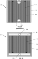
- FIG. 2A is a top view of the air side of the conventional interconnect 10
- FIG. 2B is a top view of a fuel side of the interconnect 10.
- the air side includes the air channels 8B. Air flows through the air channels 8B to a cathode electrode 3 of an adjacent fuel cell 1. In particular, the air may flow across the interconnect 10 in a first direction A as indicated by the arrows.
- Ring seals 23 may surround fuel holes 22A of the interconnect 10, to prevent fuel from contacting the cathode electrode.
- Peripheral strip-shaped seals 24 are located on peripheral portions of the air side of the interconnect 10.
- the seals 23, 24 may be formed of a glass material.
- the peripheral portions may be in the form of an elevated plateau which does not include ribs or channels.
- the surface of the peripheral regions may be coplanar with tops of the ribs 12.
- the fuel side of the interconnect 10 may include the fuel channels 8A and fuel manifolds 28 (e.g., fuel plenums). Fuel flows from one of the fuel holes 22A, into the adjacent manifold 28, through the fuel channels 8A, and to an anode 7 of an adjacent fuel cell 1. Excess fuel may flow into the other fuel manifold 28 and then into the adjacent fuel hole 22A. In particular, the fuel may flow across the interconnect 10 in a second direction B, as indicated by the arrows. The second direction B may be perpendicular to the first direction A (see FIG. 2A ).
- the fuel manifolds 28 may occupy a relatively large region of the interconnect 10, which may reduce the contact area between the interconnect 10 and an adjacent fuel cell by approximately 10%.
- the fuel manifolds 28 are also relatively deep, such that the fuel manifolds 28 represent relatively thin regions of the interconnect 10. Since the interconnect 10 is generally formed by a powder metallurgy compaction process, the density of fuel manifold regions may approach the theoretical density limit of the interconnect material. As such, the length of stroke of a compaction press used in the compaction process may be limited due to the high-density fuel manifold regions being incapable of being compacted further. As a result, the density achieved elsewhere in the interconnect 10 may be limited to a lower level by the limitation to the compaction stroke. The resultant density variation may lead to topographical variations, which may reduce the amount of contact between the interconnect 10 a fuel cell 1 and may result in lower stack yield and/or performance.
- FIG. 3A is a perspective view of a fuel cell stack 300, according to various embodiments of the present disclosure
- FIG. 3B is an exploded perspective view of a portion of the stack 300 of FIG. 3A
- FIG. 3C is a top view of the fuel side of an interconnect 400 included in the stack 300
- FIG. 3D is a schematic view of a fuel cell included in the stack 300.
- An interconnect 400 may also contain less than about 10% iron by weight, such as about 4-6% (e.g., 5%) iron by weight, may contain less than about 2% by weight, such as about zero to 1% by weight, of other materials, such as yttrium or yttria, as well as residual or unavoidable impurities.
- the ceramic phase may comprise a stabilized zirconia, such as yttria and/or scandia stabilized zirconia and/or a doped ceria, such as gadolinia, yttria and/or samaria doped ceria.
- a stabilized zirconia such as yttria and/or scandia stabilized zirconia and/or a doped ceria, such as gadolinia, yttria and/or samaria doped ceria.
- the electrolyte 312 may comprise a stabilized zirconia, such as scandia stabilized zirconia (SSZ) or yttria stabilized zirconia (YSZ).
- the electrolyte may comprise another ionically conductive material, such as a doped ceria.
- An upper most interconnect 400 and a lowermost interconnect 400 of the stack 300 may be different ones of an air end plate or fuel end plate including features for providing air or fuel, respectively, to an adjacent end fuel cell 310.
- an "interconnect" may refer to either an interconnect located between two fuel cells 310 or an end plate located at an end of the stack and directly adjacent to only one fuel cell 310. Since the stack 300 does not include ASPs and the end plates associated therewith, the stack 300 may include only two end plates. As a result, stack dimensional variations associated with the use of intra-column ASPs may be avoided.
- the stack 300 may include side baffles 302, a fuel plenum 304, and a compression assembly 306.
- the side baffles 302 may be formed of a ceramic material and may be disposed on opposing sides of the fuel cell stack 300 containing stacked fuel cells 310 and interconnects 400.
- the side baffles 302 may connect the fuel plenum 304 and the compression assembly 306, such that the compression assembly 306 may apply pressure to the stack 300.
- the side baffles 302 may be curved baffle plates, such each baffle plate covers at least portions of three sides of the fuel cell stack 300.
- Each interconnect 400 electrically connects adjacent fuel cells 310 in the stack 300.
- an interconnect 400 may electrically connect the anode electrode of one fuel cell 310 to the cathode electrode of an adjacent fuel cell 310.
- each interconnect 400 may be configured to channel air in a first direction A, such that the air may be provided to the cathode of an adjacent fuel cell 310.
- Each interconnect 400 may also be configured to channel fuel in a second direction F, such that the fuel may be provided to the anode of an adjacent fuel cell 310.
- Directions A and F may be perpendicular, or substantially perpendicular.
- the interconnects 400 may be referred to as cross-flow interconnects.
- each interconnect 400 contains two fuel inlets 402 separated by a neck portion 412 of the interconnect 400, as shown in FIG. 3B . However, more than two fuel inlets 402 may be included, such as three to five inlets separated by two to four neck portions 412.
- each interconnect 400 contains two fuel outlets 404 separated by a neck portion 414 of the interconnect 400, as shown in FIG. 3B . However, more than two fuel outlets 404 may be included, such as three to five outlets separated by two to four neck portions 414.
- the fuel inlets 402 of adjacent interconnects 400 may be aligned in the stack 300 to form one or more fuel inlet risers 403.
- the fuel outlets 404 of adjacent interconnects 400 may be aligned in the stack 300 to form one or more fuel outlet risers 405.
- the fuel inlet riser 403 may be configured to distribute fuel received from the fuel plenum 304 to the fuel cells 310.
- the fuel outlet riser 405 may be configured to provide anode exhaust received from the fuel cells 310 to the fuel plenum 304.
- the side baffles 302 may be curved around edges of the interconnects 400.
- the side baffles 302 may be disposed around the fuel inlets 402 and outlets 404 of the interconnects 400. Accordingly, the side baffles may more efficiently control air flow through air channels of the interconnects 400, which are exposed between the side baffles 302 and are described in detail with regard to FIGS. 4A and 4B .
- Each interconnect 400 may be made of or may contain electrically conductive material, such as a metal alloy (e.g., chromium-iron alloy) which has a similar coefficient of thermal expansion to that of the solid oxide electrolyte in the cells (e.g., a difference of 0-10%).
- the interconnects 400 may comprise a metal (e.g., a chromium-iron alloy, such as 4-6 weight percent iron, optionally 1 or less weight percent yttrium and balance chromium alloy), and may electrically connect the anode or fuel-side of one fuel cell 310 to the cathode or air-side of an adjacent fuel cell 310.
- An electrically conductive contact layer such as a nickel contact layer (e.g., a nickel mesh), may be provided between anode and each interconnect 400.
- a nickel contact layer e.g., a nickel mesh
- Another optional electrically conductive contact layer may be provided between the cathode electrodes and each interconnect 400.
- FIGS. 4A and 4B are plan views showing, respectively, an air side and a fuel side of the cross-flow interconnect 400, according to various embodiments of the present disclosure.
- the air side of the interconnect 400 may include ribs 406 configured to at least partially define air channels 408 configured to provide air to the cathode of a fuel cell 310 disposed thereon.
- the air side of the interconnect 400 may be divided into an air flow field 420 including the air channels 408, and riser seal surfaces 422 disposed on two opposing sides of the air flow field 420.
- One of the riser seal surfaces 422 may surround the fuel inlets 402 and the other riser seal surface 422 may surround the fuel outlets 404.
- Riser seals 424 may be disposed on the riser seal surface 422. For example, one riser seal 424 may surround the fuel inlets 402, and one riser seal 424 may surround the fuel outlets 404.
- the riser seals 424 may prevent fuel and/or anode exhaust from entering the air flow field 420 and contacting the cathode of the fuel cell 310.
- the riser seals 424 may also operate to prevent fuel from leaking out of the fuel cell stack 100 (see FIG. 3A ).
- the fuel side of the interconnect 400 may include ribs 416 that at least partially define fuel channels 418 configured to provide fuel to the anode of a fuel cell 310 disposed thereon.
- the fuel side of the interconnect 400 may be divided into a fuel flow field 430 including the fuel channels 418, and a perimeter seal surface 432 surrounding the fuel flow field 430 and the fuel inlets and outlets 402, 404.
- the ribs 416 and fuel channels 418 may extend in a direction that is perpendicular or substantially perpendicular to the direction in which the air-side channels 408 and ribs 406 extend.
- a frame-shaped perimeter seal 434 may be disposed on the perimeter seal surface 432.
- the perimeter seal 434 may be configured to prevent air entering the fuel flow field 430 and contacting the anode on an adjacent fuel cell 310.
- the perimeter seal 434 may also operate to prevent fuel from exiting the fuel risers 403, 405 and leaking out of the fuel cell stack 300 (see FIGS. 3A and 3B ).
- the seals 424, 434 may comprise a glass or ceramic seal material.
- the seal material may have a low electrical conductivity.
- the seals 424, 434 may be formed by printing one or more layers of seal material on the interconnect 400, followed by sintering.
- FIG. 4C is a sectional view illustrating one of the fuel-side ribs 416 of the interconnect 400 and the anode 314 of an adjacent fuel cell 310, according to various embodiments of the present disclosure.
- the interconnect 400 is electrically connected to the anode 314 by a Ni mesh 318 covering the fuel side of the interconnect 400.
- the Ni mesh 318 may operate as a current collector with respect to the anode 7.
- each fuel-side rib 416 of the interconnect 400 may be connected to the anode 314 in a similar manner.
- oxides or other contaminants may form over time on the surface of an interconnect, and in particular, at an interface between a Ni mesh and corresponding ribs of the interconnect. As such, the contact resistance between the Ni mesh and an interconnect may increase, which may reduce the useful life of a fuel cell stack.
- the interconnect 400 may include a contact layer 415 configured to prevent or reduce such an increase in contact resistance.
- the contact layer 415 may be formed on the tips of the ribs 416.
- the contact layer 415 may be disposed at an interface between the interconnect 400 and the Ni mesh 318 (e.g., between the rib 416 and the Ni mesh 318).
- the contact layer 415 may cover substantially all of the upper (e.g., distal) surface of the rib 416.
- the contact layer 415 may cover only a portion of the tip of the rib 416.
- the contact layer 415 may have a higher iron content than the interconnect 400.
- the contact layer 415 may have greater than 7 wt% iron, such as from about 10 to about 95 wt% iron, or about 20 to about 80 wt% iron, while the interconnect 400 may include an alloy having from about 4 to about 6 wt% iron. Accordingly, the contact layer 415 may operate to prevent oxide growth at the interface between the rib 416 and the Ni mesh 318.
- the contact layer 415 may also improve the metallurgical joining of the Ni mesh 318 and the interconnect 400.
- the thickness (e.g., depth) and/width of the contact layer 415 may be controlled to reduce mechanical distortion of the interconnect 400.
- the thickness of the contact layer 415 may range from about 5 to about 1000 ⁇ m.
- the contact layer 415 may have an iron to chromium ratio that varies in the thickness direction thereof. For example, the iron to chromium ratio may decrease as a distance from the tip of the rib 416 increases.
- the contact layer 415 may be formed by depositing an iron-based material, such as metallic iron or iron oxide, on the tips of the ribs 416.
- the interconnect 400 can then be sintered, such that the iron and chromium in the interconnect at least partially inter-diffuse, thereby creating the contact layer 415.
- iron of the contact layer 415 may partially diffuse into the tip of the rib 416, and chromium of the interconnect 400 may partially diffuse into the contact layer 415.
- the contact layer 415 may be formed by disposing iron wire on the tips of the ribs 416.
- the interconnect 400 may then be sintered to facilitate iron and chromium inter-diffusion, as described above.
- the iron wire may have a thickness (e.g., diameter) ranging from about 10 to 300 microns, such as from about 15 to about 250 microns, or from about 20 to about 200 microns.
- the iron wire may be deposited on an interconnect powder, and the resultant structure may be compressed into the shape of an interconnect, followed by sintering. In other embodiments, the iron wire may be deposited on a compressed interconnect, and the resultant structure may then be sintered.
- the contact layer 415 may be formed by contacting an iron powder to the tip of the rib 416.
- the iron powder may have an average particle size ranging from about 20 to about 400 microns, such as from about 25 to about 350 microns, or from about 30 to about 300 microns.
- the iron powder may be deposited on an interconnect powder, and the resultant structure may be compressed into the shape of an interconnect, followed by sintering.
- the iron powder and the interconnect powder may be comprised and sintered at the same time using spark plasma sintering, as described in more detail below.
- the interconnect powder may be deposited into a die cavity using a first shoe, and then the iron powder may then be deposited onto the interconnect powder using a second shoe or by a spraying process.
- the iron powder may be deposited on a compressed interconnect, or the compressed interconnect may be placed onto the iron powder ribs down, and the resultant structure may then be sintered. Methods of forming interconnects will be discussed in more detail below.
- FIG. 4D is a sectional view of a fuel cell 310 connected to the air side of an interconnect 400, according to various embodiments of the present disclosure.
- a protective coating or layer 440 may be disposed on the air side of the interconnect 400, and a cathode contact layer (CCL) 442 may be disposed on the coating 440.
- CCL cathode contact layer
- the protective coating 440 and/or the CCL 442 may be deposited only on the tops of the cathode side ribs 406, without depositing the protective coating 440 and/or the CCL 442 in the oxidant (e.g., air) channels 408 (i.e., without depositing the coating 440 and/or the CCL 442 on or over the sidewalls of the ribs 406 and/or without depositing the coating 440 and/or the CCL on or over the bottom of the oxidant channels 408).
- the oxidant e.g., air
- the coating 440 may be configured to limit the diffusion of chromium ions (e.g., Cr 3+ ) from the interconnect 400 and into cathode 316 and into seals 424.
- the coating 440 may also be configured to suppress the formation of the native oxide on the surface of the interconnect 400.
- the native oxide is formed when oxygen reacts with chromium in the interconnect alloy to form a relatively high resistance layer of Cr 2 O 3 . If the interconnect coating 440 can suppress the transport of oxygen and water vapor from the air to the surface of the interconnect 400, then the kinetics of oxide growth can be reduced.
- the CCL 442 may be an electrically conductive metal oxide layer configured to improve an electrical connection between the interconnect 400 and the cathode 316.
- the CCL 442 may include metal oxide materials that have a low cation diffusivity in the perovskite family, such as a lanthanum strontium oxide, e.g., La 1-x Sr x MnO 3 (LSM), where 0.1 ⁇ x ⁇ 0.3, such as 0.1 ⁇ x ⁇ 0.2.
- LSM La 1-x Sr x MnO 3
- the material has high electronic conductivity yet low anion and cation diffusion.
- perovskites such as La 1-x Sr x FeO 3-d , La 1-x Sr x CoO 3-d , and La 1-x Sr x Co 1-y Fe y O 3-d all exhibit high electronic conduction and low cation conduction (low chromium diffusion rates) and may be used as the CCL 442.
- the glass material may be selected from various compositions, such as alumino-silicate, boro-silicate, boro-aluminate, and alkali-free compositions, and may include Al, Si, Ca, Ba, B, La, Sr, Mg, or mixtures thereof.
- a lubricant may not be necessary to facilitate compaction and may be omitted from the interconnect body powder 204.
- the interconnect body powder 204 may optionally include a lubricant to facilitate compaction.
- the DC voltage may result in Joule heating, due to current flow through the fused particles.
- the temperature of the composite interconnect material 410 may be increased to a sintering temperature ranging from about 1000 °C to about 1500 °C, such as from about 1100 °C to about 1475 °C, or about 1250 °C to 1450 °C.
- the pressure applied to the composite interconnect material 210 by the punches 201, 205 may be increased to a pressure of at least 25 MPa, such as a pressure ranging from about 30 MPa to about 150 MPa, such as to about 40 MPa to about 80 MPa, or about 50 MPa to about 60 MPa.
- the sintering temperature and the pressure may be maintained until the composite interconnect material 210 is sufficiently sintered and/or densified to form a densified interconnect 400.
- the applied heat and pressure may result in the plastic deformation and compaction of particles of the composite interconnect material 210, thereby forming a densified, sintered interconnect 400, as shown in FIG. 5F .
- the temperature and pressure may be maintained for a time period ranging from about 15 minutes to about 45 minutes, such as from about 10 minutes to about 60 minutes, or about 20 to 40 minutes, depending on a desired amount of densification and/or sintering.
- FIGS. 6A-6E illustrate a SPS process for forming an interconnect 400, according to an alternative embodiment of the present disclosure.
- the SPS process may be similar to the process of FIGS. 5A-5F . As such, only the difference therebetween will be discussed in detail.
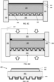
- the protective powder 206 is formed below the interconnect body powder 204 in the die 203.
- a release layer 202A such as a graphite sheet of foil, may be positioned in the die 203 on the lower punch 201.
- a protective powder 206 may be deposited on the release layer 202A.
- the interconnect body powder 204 may be loaded into the die 203 and on the protective powder 206.
- a contact material 208 may be optionally loaded on the interconnect body powder 204.
- the contact material 208 may be an iron-containing material, such as metallic iron or iron oxide, and may be in the form of a powder or a wire.
- the contact material 208 may be loaded as a continuous layer or as a discontinuous layer.
- the contact material 208 may be loaded on areas of the interconnect body powder 204 that subsequently form tips of interconnect ribs.
- the contact material 208 comprises iron rich powder (e.g., a powder containing from about 10 to about 95 wt.% iron powder and remainder Cr powder, or a Fe-Cr alloy powder containing from about 10 to about 95 wt.% Fe and remainder Cr).
- the contact material 208 may be arranged, such that when the interconnect body powder 204 is compressed, the contact material 208 is disposed between ribs 205R of the upper punch 205.
- the contact material 208 may be deposited using a shoe, a spray deposition method, a screen-printing method, or the like.
- the powders may be compressed between the lower punch 201 and the upper punch 205.
- a SPS process may then be performed to sinter the powders and form the interconnect 400, as described above.
- the release layers 202A, 202B may be removed to complete the interconnect 400 including the protective coating 440 on the air side and the contact layer 415 on the fuel side (e.g., on the tips of the fuel side ribs 416).
- the above methods may be performed in an SPS powder pressing apparatus that allows for more than one interconnect to be formed at a time.
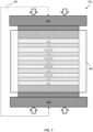
- FIG. 7 illustrates a SPS apparatus 211 configured to produce multiple interconnects simultaneously.
- the apparatus 211 may include a die (i.e., die cavity) 203, a power supply 207, a lower ram 213 and an upper ram 215.
- the die 203 may be configured to receive multiple lower and upper punches 201, 205.
- a single punch may be configured to make several interconnects in the same plane as well. If multiple interconnects or coplanar interconnects are stacked vertically, then an intermediate punch with air side and fuel side is used.
- a composite interconnect material 210 which may comprise the interconnect body powder and optionally the protective powder and/or the contact material as described above, may be loaded between each pair of the lower and upper punches 201, 205.
- release layers 202A, 202B may be used to separate layers of the composite interconnect material from the punches 201, 205.
- the power supply 207 may be configured to apply a pulsed DC voltage to the composite interconnect material 210, and the lower and upper rams 213, 215 may be configured to apply pressure to the composite interconnect material 210, while the composite interconnect material 210 is heated by the applied voltage. Accordingly, the apparatus 211 may be configured to simultaneously produce multiple sintered interconnects 400, as shown in FIGS. 5F or 6E .
- the interconnect 400 may be placed into a fuel cell stack, such as a solid oxide fuel cell stack. Fuel cell systems of the embodiments of the present disclosure are designed to reduce greenhouse gas emissions and have a positive impact on the climate. In alternative embodiments, the interconnect 400 may be placed into an electrolyzer stack, such as a solid oxide electrolyzer stack. Thus, the interconnect may be used in any suitable electrochemical device stack.
- the interconnect 400 is not oxidized at a temperature above room temperature (e.g., between 100 and 900 degrees Celsius) between the SPS step and the step of placing the interconnect into the fuel cell or electrolyzer stack.
- FIG. 8A is a cross-sectional micrograph showing an interconnect formed by SPS and comprising a body 401 formed of a chromium alloy and a protective coating 440 formed of LSM, according to various embodiments of the present disclosure.
- FIGS. 8B and 8C are higher magnification micrographs showing an interface region formed between the protective coating and the body of the interconnect of FIG. 8A .
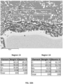
- EDS energy dispersive X-ray spectroscopy
- Region 5 was located in an outer portion of an inner layer of the interface region, and Region 6 was located in an inner portion of the inner layer of the interface region.
- the Region 5 and 6 results indicated that chromium diffusion decreased in the inner layer of the interface region as distance from the interconnect body 401 increased. As such, the results indicate that inter-diffusion of interconnect body and protective coating materials occurred at the interface region.
- a chromium oxide interface layer formed between the interconnect body 401 and the protective coating 440 is a chromium oxide interface layer formed between the interconnect body 401 and the protective coating 440.
- FIGS. 9A and 9B are cross-sectional micrographs showing an interconnect comprising a body formed of a chromium alloy and a protective coating formed of MCO using SPS in a vacuum atmosphere, according to various embodiments of the present disclosure.
- the MCO coating 410 in Regions 4 and 5 included between 50 and 68 wt.% manganese, between 30 and 39 wt.% cobalt, and between 9 and 12 wt.% oxygen. Less than 1 wt.% of respective chromium and iron diffused into the MCO coating 410.
- interconnects that are formed by SPS can be compressed and sintered in one step in the same apparatus, thus simplifying the fabrication method.
- contact layers and/or protective coatings may be formed on the interconnects during the SPS process without utilizing a separate coating process, such as plasma spraying, wet spraying or the like, which further simplifies the fabrication method.
- the SPS process may form high density interconnects without utilizing an oxidation process.
- the disclosed methods may also provide interconnects having a higher electric and/or thermal conductivity than interconnects formed by conventional methods. Accordingly, the disclosed methods may provide higher performance interconnects at a lower cost than conventional methods.
Landscapes
- Chemical & Material Sciences (AREA)
- Engineering & Computer Science (AREA)
- Manufacturing & Machinery (AREA)
- Chemical Kinetics & Catalysis (AREA)
- Electrochemistry (AREA)
- General Chemical & Material Sciences (AREA)
- Life Sciences & Earth Sciences (AREA)
- Sustainable Development (AREA)
- Sustainable Energy (AREA)
- Materials Engineering (AREA)
- Mechanical Engineering (AREA)
- Composite Materials (AREA)
- Metallurgy (AREA)
- Organic Chemistry (AREA)
- Optics & Photonics (AREA)
- Physics & Mathematics (AREA)
- Ceramic Engineering (AREA)
- Fuel Cell (AREA)
Applications Claiming Priority (1)
| Application Number | Priority Date | Filing Date | Title |
|---|---|---|---|
| US202263375407P | 2022-09-13 | 2022-09-13 |
Publications (2)
| Publication Number | Publication Date |
|---|---|
| EP4372851A2 true EP4372851A2 (de) | 2024-05-22 |
| EP4372851A3 EP4372851A3 (de) | 2024-07-17 |
Family
ID=87863195
Family Applications (1)
| Application Number | Title | Priority Date | Filing Date |
|---|---|---|---|
| EP23194167.5A Pending EP4372851A3 (de) | 2022-09-13 | 2023-08-30 | Verfahren zur herstellung einer verbindung für einen stapel einer elektrochemischen vorrichtung mittels spark-plasma-sintern |
Country Status (5)
| Country | Link |
|---|---|
| US (1) | US20240082916A1 (de) |
| EP (1) | EP4372851A3 (de) |
| KR (1) | KR20240036460A (de) |
| CA (1) | CA3210539A1 (de) |
| TW (1) | TW202430294A (de) |
Citations (2)
| Publication number | Priority date | Publication date | Assignee | Title |
|---|---|---|---|---|
| US20130230792A1 (en) | 2012-03-01 | 2013-09-05 | Bloom Energy Corporation | Coatings for Metal Interconnects to Reduce SOFC Degradation |
| US9452475B2 (en) | 2012-03-01 | 2016-09-27 | Bloom Energy Corporation | Coatings for SOFC metallic interconnects |
Family Cites Families (2)
| Publication number | Priority date | Publication date | Assignee | Title |
|---|---|---|---|---|
| FR2961350B1 (fr) * | 2010-06-11 | 2012-08-03 | Commissariat Energie Atomique | Procede de fabrication de cellules electrochimiques elementaires pour systemes electrochimiques producteurs d'energie ou d'hydrogene, notamment du type sofc et eht |
| US10873092B2 (en) * | 2017-02-27 | 2020-12-22 | Bloom Energy Corporation | Fuel cell interconnect with reduced voltage degradation and manufacturing method |
-
2023
- 2023-08-30 TW TW112132761A patent/TW202430294A/zh unknown
- 2023-08-30 CA CA3210539A patent/CA3210539A1/en active Pending
- 2023-08-30 US US18/458,298 patent/US20240082916A1/en active Pending
- 2023-08-30 KR KR1020230114254A patent/KR20240036460A/ko active Pending
- 2023-08-30 EP EP23194167.5A patent/EP4372851A3/de active Pending
Patent Citations (2)
| Publication number | Priority date | Publication date | Assignee | Title |
|---|---|---|---|---|
| US20130230792A1 (en) | 2012-03-01 | 2013-09-05 | Bloom Energy Corporation | Coatings for Metal Interconnects to Reduce SOFC Degradation |
| US9452475B2 (en) | 2012-03-01 | 2016-09-27 | Bloom Energy Corporation | Coatings for SOFC metallic interconnects |
Also Published As
| Publication number | Publication date |
|---|---|
| TW202430294A (zh) | 2024-08-01 |
| US20240082916A1 (en) | 2024-03-14 |
| CA3210539A1 (en) | 2024-03-13 |
| KR20240036460A (ko) | 2024-03-20 |
| EP4372851A3 (de) | 2024-07-17 |
Similar Documents
| Publication | Publication Date | Title |
|---|---|---|
| US6051330A (en) | Solid oxide fuel cell having vias and a composite interconnect | |
| US11456464B2 (en) | Fuel cell interconnect with reduced voltage degradation and manufacturing method | |
| JP2009507356A (ja) | 一体的な密封部および支持体を備えたセラミックメンブラン、ならびにそれを包含する電気化学的電池および電気化学的電池積重構造 | |
| TWI761482B (zh) | 合金構件之製造方法、合金構件、電化學元件、電化學模組、電化學裝置、能源系統及固態氧化物型燃料電池 | |
| US20120082920A1 (en) | Co-fired metal interconnect supported sofc | |
| EP4364870A1 (de) | Bindemittelstrahldruck einer metallischen verbindung für elektrochemischen festoxidzellenstapel | |
| US20230072908A1 (en) | Rigidly Bonded Metal Supported Electro-Chemical Stack | |
| US20250349866A1 (en) | Methods and devices for preventing thermally-induced stress cracks in large footprint solid oxide fuel cell columns | |
| US11962041B2 (en) | Methods for manufacturing fuel cell interconnects using 3D printing | |
| JP4512911B2 (ja) | 固体電解質型燃料電池 | |
| JPH10172590A (ja) | 固体電解質型燃料電池 | |
| US20240347739A1 (en) | Inert atmosphere sintering of electrochemical cell stack interconnects | |
| US20240082916A1 (en) | Method of forming an interconnect for an electrochemical device stack using spark plasma sintering | |
| EP4343023B1 (de) | Verfahren zur herstellung einer verbindungsbeschichtung für einen stapel einer elektrochemischen vorrichtung mittels lasersintern | |
| EP4235878B1 (de) | Mit einem übergangsmetallelement legierte brennstoffzellenverbindung und herstellungsverfahren dafür | |
| US20240332560A1 (en) | Electrochemical cell stacks including interconnect end plates | |
| CN110447134A (zh) | 电化学元件、电化学模块、固体氧化物型燃料电池和制造方法 | |
| JP2002358976A (ja) | 固体電解質型燃料電池 | |
| KR20200135471A (ko) | 금속판, 전기화학 소자, 전기화학 모듈, 전기화학 장치, 에너지 시스템, 고체 산화물형 연료 전지, 및 금속판의 제조 방법 | |
| EP4699174A1 (de) | Elektrochemische zellenstapelverbindungen mit kupferhaltigen schutzschichten und verfahren zur herstellung davon | |
| CN120072956A (zh) | 固体氧化物燃料电池及其制造方法 |
Legal Events
| Date | Code | Title | Description |
|---|---|---|---|
| PUAI | Public reference made under article 153(3) epc to a published international application that has entered the european phase |
Free format text: ORIGINAL CODE: 0009012 |
|
| STAA | Information on the status of an ep patent application or granted ep patent |
Free format text: STATUS: THE APPLICATION HAS BEEN PUBLISHED |
|
| AK | Designated contracting states |
Kind code of ref document: A2 Designated state(s): AL AT BE BG CH CY CZ DE DK EE ES FI FR GB GR HR HU IE IS IT LI LT LU LV MC ME MK MT NL NO PL PT RO RS SE SI SK SM TR |
|
| PUAL | Search report despatched |
Free format text: ORIGINAL CODE: 0009013 |
|
| AK | Designated contracting states |
Kind code of ref document: A3 Designated state(s): AL AT BE BG CH CY CZ DE DK EE ES FI FR GB GR HR HU IE IS IT LI LT LU LV MC ME MK MT NL NO PL PT RO RS SE SI SK SM TR |
|
| RIC1 | Information provided on ipc code assigned before grant |
Ipc: H01M 8/12 20160101ALN20240611BHEP Ipc: B22F 3/10 20060101ALI20240611BHEP Ipc: B22F 3/02 20060101ALI20240611BHEP Ipc: H01M 8/0228 20160101ALI20240611BHEP Ipc: H01M 8/0217 20160101ALI20240611BHEP Ipc: H01M 8/021 20160101AFI20240611BHEP |
|
| STAA | Information on the status of an ep patent application or granted ep patent |
Free format text: STATUS: REQUEST FOR EXAMINATION WAS MADE |
|
| 17P | Request for examination filed |
Effective date: 20250115 |