EP4372876B1 - Befestigungsvorrichtung für ein batteriepack, batteriepack und verfahren - Google Patents
Befestigungsvorrichtung für ein batteriepack, batteriepack und verfahren Download PDFInfo
- Publication number
- EP4372876B1 EP4372876B1 EP22208060.8A EP22208060A EP4372876B1 EP 4372876 B1 EP4372876 B1 EP 4372876B1 EP 22208060 A EP22208060 A EP 22208060A EP 4372876 B1 EP4372876 B1 EP 4372876B1
- Authority
- EP
- European Patent Office
- Prior art keywords
- fastener
- battery pack
- fixating member
- battery module
- battery
- Prior art date
- Legal status (The legal status is an assumption and is not a legal conclusion. Google has not performed a legal analysis and makes no representation as to the accuracy of the status listed.)
- Active
Links
Images

Classifications
-
- H—ELECTRICITY
- H01—ELECTRIC ELEMENTS
- H01M—PROCESSES OR MEANS, e.g. BATTERIES, FOR THE DIRECT CONVERSION OF CHEMICAL ENERGY INTO ELECTRICAL ENERGY
- H01M50/00—Constructional details or processes of manufacture of the non-active parts of electrochemical cells other than fuel cells, e.g. hybrid cells
- H01M50/20—Mountings; Secondary casings or frames; Racks, modules or packs; Suspension devices; Shock absorbers; Transport or carrying devices; Holders
- H01M50/202—Casings or frames around the primary casing of a single cell or a single battery
-
- H—ELECTRICITY
- H01—ELECTRIC ELEMENTS
- H01M—PROCESSES OR MEANS, e.g. BATTERIES, FOR THE DIRECT CONVERSION OF CHEMICAL ENERGY INTO ELECTRICAL ENERGY
- H01M50/00—Constructional details or processes of manufacture of the non-active parts of electrochemical cells other than fuel cells, e.g. hybrid cells
- H01M50/20—Mountings; Secondary casings or frames; Racks, modules or packs; Suspension devices; Shock absorbers; Transport or carrying devices; Holders
- H01M50/262—Mountings; Secondary casings or frames; Racks, modules or packs; Suspension devices; Shock absorbers; Transport or carrying devices; Holders with fastening means, e.g. locks
- H01M50/264—Mountings; Secondary casings or frames; Racks, modules or packs; Suspension devices; Shock absorbers; Transport or carrying devices; Holders with fastening means, e.g. locks for cells or batteries, e.g. straps, tie rods or peripheral frames
-
- H—ELECTRICITY
- H01—ELECTRIC ELEMENTS
- H01M—PROCESSES OR MEANS, e.g. BATTERIES, FOR THE DIRECT CONVERSION OF CHEMICAL ENERGY INTO ELECTRICAL ENERGY
- H01M50/00—Constructional details or processes of manufacture of the non-active parts of electrochemical cells other than fuel cells, e.g. hybrid cells
- H01M50/20—Mountings; Secondary casings or frames; Racks, modules or packs; Suspension devices; Shock absorbers; Transport or carrying devices; Holders
- H01M50/204—Racks, modules or packs for multiple batteries or multiple cells
- H01M50/207—Racks, modules or packs for multiple batteries or multiple cells characterised by their shape
- H01M50/209—Racks, modules or packs for multiple batteries or multiple cells characterised by their shape adapted for prismatic or rectangular cells
-
- H—ELECTRICITY
- H01—ELECTRIC ELEMENTS
- H01M—PROCESSES OR MEANS, e.g. BATTERIES, FOR THE DIRECT CONVERSION OF CHEMICAL ENERGY INTO ELECTRICAL ENERGY
- H01M50/00—Constructional details or processes of manufacture of the non-active parts of electrochemical cells other than fuel cells, e.g. hybrid cells
- H01M50/20—Mountings; Secondary casings or frames; Racks, modules or packs; Suspension devices; Shock absorbers; Transport or carrying devices; Holders
- H01M50/244—Secondary casings; Racks; Suspension devices; Carrying devices; Holders characterised by their mounting method
-
- H—ELECTRICITY
- H01—ELECTRIC ELEMENTS
- H01M—PROCESSES OR MEANS, e.g. BATTERIES, FOR THE DIRECT CONVERSION OF CHEMICAL ENERGY INTO ELECTRICAL ENERGY
- H01M50/00—Constructional details or processes of manufacture of the non-active parts of electrochemical cells other than fuel cells, e.g. hybrid cells
- H01M50/20—Mountings; Secondary casings or frames; Racks, modules or packs; Suspension devices; Shock absorbers; Transport or carrying devices; Holders
- H01M50/249—Mountings; Secondary casings or frames; Racks, modules or packs; Suspension devices; Shock absorbers; Transport or carrying devices; Holders specially adapted for aircraft or vehicles, e.g. cars or trains
-
- H—ELECTRICITY
- H01—ELECTRIC ELEMENTS
- H01M—PROCESSES OR MEANS, e.g. BATTERIES, FOR THE DIRECT CONVERSION OF CHEMICAL ENERGY INTO ELECTRICAL ENERGY
- H01M50/00—Constructional details or processes of manufacture of the non-active parts of electrochemical cells other than fuel cells, e.g. hybrid cells
- H01M50/20—Mountings; Secondary casings or frames; Racks, modules or packs; Suspension devices; Shock absorbers; Transport or carrying devices; Holders
- H01M50/262—Mountings; Secondary casings or frames; Racks, modules or packs; Suspension devices; Shock absorbers; Transport or carrying devices; Holders with fastening means, e.g. locks
-
- H—ELECTRICITY
- H01—ELECTRIC ELEMENTS
- H01M—PROCESSES OR MEANS, e.g. BATTERIES, FOR THE DIRECT CONVERSION OF CHEMICAL ENERGY INTO ELECTRICAL ENERGY
- H01M50/00—Constructional details or processes of manufacture of the non-active parts of electrochemical cells other than fuel cells, e.g. hybrid cells
- H01M50/20—Mountings; Secondary casings or frames; Racks, modules or packs; Suspension devices; Shock absorbers; Transport or carrying devices; Holders
- H01M50/271—Lids or covers for the racks or secondary casings
-
- A—HUMAN NECESSITIES
- A44—HABERDASHERY; JEWELLERY
- A44B—BUTTONS, PINS, BUCKLES, SLIDE FASTENERS, OR THE LIKE
- A44B1/00—Buttons
-
- A—HUMAN NECESSITIES
- A44—HABERDASHERY; JEWELLERY
- A44B—BUTTONS, PINS, BUCKLES, SLIDE FASTENERS, OR THE LIKE
- A44B19/00—Slide fasteners
- A44B19/42—Making by processes not fully provided for in one other class, e.g. B21D53/50, B21F45/18, B22D17/16, B29D5/00
- A44B19/44—Securing metal interlocking members to ready-made stringer tapes
- A44B19/46—Securing separate interlocking members
-
- H—ELECTRICITY
- H01—ELECTRIC ELEMENTS
- H01M—PROCESSES OR MEANS, e.g. BATTERIES, FOR THE DIRECT CONVERSION OF CHEMICAL ENERGY INTO ELECTRICAL ENERGY
- H01M2220/00—Batteries for particular applications
- H01M2220/20—Batteries in motive systems, e.g. vehicle, ship, plane
-
- Y—GENERAL TAGGING OF NEW TECHNOLOGICAL DEVELOPMENTS; GENERAL TAGGING OF CROSS-SECTIONAL TECHNOLOGIES SPANNING OVER SEVERAL SECTIONS OF THE IPC; TECHNICAL SUBJECTS COVERED BY FORMER USPC CROSS-REFERENCE ART COLLECTIONS [XRACs] AND DIGESTS
- Y02—TECHNOLOGIES OR APPLICATIONS FOR MITIGATION OR ADAPTATION AGAINST CLIMATE CHANGE
- Y02E—REDUCTION OF GREENHOUSE GAS [GHG] EMISSIONS, RELATED TO ENERGY GENERATION, TRANSMISSION OR DISTRIBUTION
- Y02E60/00—Enabling technologies; Technologies with a potential or indirect contribution to GHG emissions mitigation
- Y02E60/10—Energy storage using batteries
Definitions
- the disclosure relates generally to a battery pack.
- the disclosure relates to a battery pack fastening arrangement, a battery pack comprising such a fastening arrangement and a fastening method.
- the disclosure can be applied in heavy-duty vehicles, such as trucks, buses, and construction equipment. Although the disclosure may be described with respect to a particular vehicle, the disclosure is not restricted to any particular vehicle. The disclosure could also be applied in stationary applications.
- Electrical storage systems are used to store energy for subsequent use.
- One example of an electrical storage system is a battery, such as a rechargeable battery for an electric vehicle.
- An electrical storage system can comprise one or several battery packs. Each battery pack in turn comprises a plurality of battery cells. The battery cells are sometimes grouped together to form battery modules. By letting the battery pack consist of several battery modules, parts of the battery pack can be replaced without replacing the entire battery pack.
- the battery pack generally comprises a structure for supporting the battery modules within the battery pack, such as a battery pack cover.
- the battery modules are thus attached to the battery pack cover which fixedly retains the battery modules within the vehicle.
- the arrangement for fastening the battery module to the battery pack cover should preferably be able to compensate for tolerance differences of the battery pack cover and the battery module.
- WO 2020/030649 A1 discloses a fixing element protruding from a housing.
- a previous solution includes assembling of the battery module tight towards one side of the battery pack cover and arranging a tolerance compensating fastener, such as a tolerance compensating screw, to the opposite side of the battery pack cover.
- the present solution aims at providing a fastening device which at least partly overcomes these previous problems.
- a fastening device configured to fasten a battery module to a battery pack cover
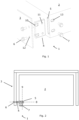
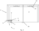
- the fastening device comprising a fixating member adapted to be received within, and protrude from, a recess of the battery module, a first fastener adapted to fasten the fixating member to the battery pack cover and a second fastener adapted to fasten the fixating member to the battery module, for securement within the recess of the battery module.
- a fastening direction of the first fastener is perpendicular to a fastening direction of the second fastener, and the first fastener is configured to move the fixating member into contact with the battery pack cover.
- the invention seeks to provide an improved tolerance compensating fastening device for a battery pack.
- a technical benefit may include that the fastening device can be used for tolerance compensation, but without the risk of unfastening as the fixating member prevents momentum from being induced in the fasteners.
- the fixating member is plate shaped.
- the first fastener comprises a first threaded fastener
- the fixating member comprises a first threaded aperture for receiving the first threaded fastener.
- a technical benefit may include that the threaded fastener can be used to move the fixating member into tight contact with the battery pack cover and hold it there without the addition of further parts.
- the second fastener comprises a second threaded fastener
- the fixating member comprises a second threaded aperture for receiving the second threaded fastener
- the invention seeks to provide an improved method for assembling a battery pack.
- a technical benefit may include that the fixating member can be arranged within the recess prior to positioning the battery module in the battery pack, and then moved into place with the first fastener. Thereby, assembly of the battery pack may be facilitated, while tolerances are accounted for.
- the second fastener comprises a second threaded fastener
- the fixating member comprises a second threaded aperture for receiving the second threaded fastener
- a battery pack for an electrical storage system comprising a battery pack cover, a battery module and a fastening device, the fastening device comprising a fixating member, the fixating member being received within, and protruding from, a recess of the battery module.
- the fastening device of the third aspect further comprises a first fastener for fastening the fixating member to the battery pack cover, and a second fastener for fastening the fixating member to the battery module, for securement within the recess of the battery module.
- a fastening direction of the first fastener is perpendicular to a fastening direction of the second fastener and the first fastener is configured to move the fixating member into contact with the battery pack cover.
- the second fastener comprises a second threaded fastener
- the fixating member comprises a second threaded aperture for receiving the second threaded fastener
- the battery module comprises a second through-hole for attaching the second threaded fastener to the battery module.
- an extension of the second through-hole exceeds a length of the second fastener in the first fastening direction to allow fastening of the fixating member at different positions within the recess of the battery module.
- a technical benefit may include that the second fastener can be positioned in varying positions to adapt to the position of the fixating member.
- the battery pack further comprises a first engaging member arranged at the battery module, a second engaging member arranged at the battery pack cover, and a third fastener wherein the first engaging member is configured to engage with the second engaging member to fixate the battery module to the battery pack cover in a first battery pack direction and a second battery pack direction, and the third fastener extending through the battery module to fixate the battery module to the battery pack cover in a third battery pack direction.
- the first engaging member comprises a first protrusion and the second engaging member comprises a second protrusion, the second protrusion comprising a recess configured to engage with the first protrusion.
- the battery pack cover comprises a third threaded aperture for receiving the third fastener.
- an electrical storage system comprising a battery pack in accordance with the present disclosure is provided.
- a vehicle comprising an electrical storage system in accordance with the present disclosure is provided.
- the present disclosure aims at providing a fastening device which can be used for tolerance compensation without being subjected to unfastening. This is solved by a fastening device, battery pack and method as described below in relation to the disclosed figures.
Landscapes
- Chemical & Material Sciences (AREA)
- Chemical Kinetics & Catalysis (AREA)
- Electrochemistry (AREA)
- General Chemical & Material Sciences (AREA)
- Engineering & Computer Science (AREA)
- Aviation & Aerospace Engineering (AREA)
- Battery Mounting, Suspending (AREA)
Claims (15)
- Befestigungsvorrichtung (1), die konfiguriert ist, um ein Batteriemodul (2) an einer Batteriepackabdeckung (3) zu befestigen, die Befestigungsvorrichtung (1) umfassendein Befestigungselement (4), das so angepasst ist, dass es in einer Aussparung (5) des Batteriemoduls (2) aufgenommen wird und aus dieser hervorsteht,ein erstes Befestigungsmittel (6), das angepasst ist, um das Befestigungselement (4) an der Batteriepackabdeckung (3) zu befestigen, undein zweites Befestigungsmittel (7), das angepasst ist, um das Befestigungselement (4) an dem Batteriemodul (2) zu befestigen, um es in der Aussparung (5) des Batteriemoduls (2) zu sichern,wobei eine Befestigungsrichtung (8) des ersten Befestigungsmittels (6) senkrecht zu einer Befestigungsrichtung (9) des zweiten Befestigungsmittels (7) ist, undwobei das erste Befestigungsmittel (6) konfiguriert ist, um das Befestigungselement (4) in Kontakt mit der Batteriepackabdeckung (3) zu bringen.
- Befestigungsvorrichtung (1) nach Anspruch 1, wobei das Befestigungselement (4) plattenförmig ist.
- Befestigungsvorrichtung (1) nach einem der Ansprüche 1-2, wobei das erste Befestigungsmittel (6) ein erstes mit Gewinde versehenes Befestigungsmittel umfasst und wobei das Befestigungselement (4) eine erste mit Gewinde versehene Öffnung (10) zur Aufnahme des ersten mit Gewinde versehenen Befestigungsmittels umfasst.
- Befestigungsvorrichtung (1) nach einem der Ansprüche 1-3, wobei das zweite Befestigungsmittel (7) ein zweites mit Gewinde versehenes Befestigungsmittel umfasst, und wobei das Befestigungselement (4) eine zweite mit Gewinde versehene Öffnung (11) zur Aufnahme des zweiten mit Gewinde versehenen Befestigungsmittels umfasst.
- Verfahren zum Befestigen eines Batteriemoduls (2) an einer Batteriepackabdeckung (3), das Verfahren umfassend- Bereitstellen (S1) einer Batteriepackabdeckung (3), eines Batteriemoduls (2) und einer Befestigungsvorrichtung (1), die Befestigungsvorrichtung (1) umfassendein Befestigungselement (4), das so angepasst ist, dass es in einer Aussparung (5) des Batteriemoduls (2) aufgenommen wird und aus dieser hervorsteht,ein erstes Befestigungsmittel (6), das angepasst ist, um das Befestigungselement (4) an der Batteriepackabdeckung (3) zu befestigen, undein zweites Befestigungsmittel (7), das angepasst ist, um das Befestigungselement (4) an dem Batteriemodul (2) zu befestigen, um es in der Aussparung (5) des Batteriemoduls (2) zu sichern,- Anordnen (S2) des Befestigungselements (4) der Befestigungsvorrichtung (1) in der Aussparung (5) des Batteriemoduls (2), wobei ein Teil des Befestigungselements (4) aus der Aussparung herausragen kann,- Befestigen (S3) des ersten Befestigungsmittels (6), wodurch das Befestigungselement (4) in Kontakt mit der Batteriepackabdeckung (3) gebracht wird, und- Befestigen (S4) des zweiten Befestigungsmittels (7), um das Befestigungselement (4) in der Aussparung (5) des Batteriemoduls (2) zu befestigen.
- Verfahren nach Anspruch 5, wobei das Befestigungselement (4) plattenförmig ist.
- Verfahren nach einem der Ansprüche 5-6, wobei das erste Befestigungsmittel (6) ein erstes mit Gewinde versehenes Befestigungsmittel umfasst und wobei das Befestigungselement (4) eine erste mit Gewinde versehene Öffnung (10) zur Aufnahme des ersten mit Gewinde versehenen Befestigungsmittels (6) umfasst.
- Verfahren nach einem der Ansprüche 6-7, wobei das zweite Befestigungsmittel (7) ein zweites mit Gewinde versehenes Befestigungsmittel umfasst, und wobei das Befestigungselement (4) eine zweite mit Gewinde versehene Öffnung (11) zur Aufnahme des zweiten mit Gewinde versehenen Befestigungsmittels umfasst.
- Batteriepack für ein elektrisches Speichersystem, das Batteriepack umfassendeine Batteriepackabdeckung (3),ein Batteriemodul (2), undeine Befestigungsvorrichtung (1), die Befestigungsvorrichtung (1) umfassendein Befestigungselement (4), wobei das Befestigungselement (4) in einer Aussparung (5) des Batteriemoduls (2) aufgenommen wird und aus dieser hervorsteht,ein erstes Befestigungsmittel (6) zum Befestigen des Befestigungselements (4) an der Batteriepackabdeckung (3), undein zweites Befestigungsmittel (7) zum Befestigen des Befestigungselements (4) am Batteriemodul (2), um es in der Aussparung (5) des Batteriemoduls (2) zu sichern,wobei eine Befestigungsrichtung (8) des ersten Befestigungsmittels (6) senkrecht zu einer Befestigungsrichtung (9) des zweiten Befestigungsmittels (7) ist, undwobei das erste Befestigungsmittel (6) konfiguriert ist, um das Befestigungselement (5) in Kontakt mit der Batteriepackabdeckung (3) zu bringen.
- Batteriepack nach Anspruch 9, wobei das erste Befestigungsmittel (6) ein erstes mit Gewinde versehenes Befestigungsmittel umfasst, wobei das Befestigungselement (4) eine erste mit Gewinde versehene Öffnung (10) zur Aufnahme des ersten Befestigungsmittels (6) umfasst, und wobei die Batteriepackabdeckung (3) ein erstes Durchgangsloch (12) zur Befestigung des ersten Befestigungsmittels (6) an der Batteriepackabdeckung (3) umfasst.
- Batteriepack nach einem der Ansprüche 9-10, wobei das zweite Befestigungsmittel (7) ein zweites mit Gewinde versehenes Befestigungsmittel umfasst, wobei das Befestigungselement (4) eine zweite mit Gewinde versehene Öffnung (11) zur Aufnahme des zweiten mit Gewinde versehenen Befestigungsmittels umfasst, und wobei das Batteriemodul (2) ein zweites Durchgangsloch (13) zur Befestigung des zweiten mit Gewinde versehenen Befestigungsmittels an dem Batteriemodul (2) umfasst.
- Batteriepack nach Anspruch 11, wobei eine Erweiterung des zweiten Durchgangslochs (13) eine Länge des zweiten Befestigungsmittels (6) in der ersten Befestigungsrichtung (8) übersteigt, um eine Befestigung des Befestigungselements (4) an verschiedenen Positionen innerhalb der Aussparung (5) des Batteriemoduls (2) zu ermöglichen.
- Batteriepack nach einem der Ansprüche 9-12, ferner umfassendein erstes Eingriffselement (14), das am Batteriemodul angeordnet ist,ein zweites Eingriffselement (15), das an der Batteriepackabdeckung angeordnet ist, undein drittes Befestigungsmittel (16),wobei das erste Eingriffselement (14) so konfiguriert ist, dass es mit dem zweiten Eingriffselement (15) in Eingriff kommt, um das Batteriemodul (2) an der Batteriepackabdeckung (3) in einer ersten Batteriepackrichtung und einer zweiten Batteriepackrichtung zu befestigen, undwobei sich das dritte Befestigungsmittel (16) durch das Batteriemodul (2) hindurch erstreckt, um das Batteriemodul (2) an der Batteriepackabdeckung (3) in einer dritten Batteriepackrichtung zu befestigen.
- Elektrisches Speichersystem umfassend das Batteriepack nach Anspruch 9.
- Fahrzeug umfassend ein elektrisches Speichersystem nach Anspruch 14.
Priority Applications (2)
| Application Number | Priority Date | Filing Date | Title |
|---|---|---|---|
| EP22208060.8A EP4372876B1 (de) | 2022-11-17 | 2022-11-17 | Befestigungsvorrichtung für ein batteriepack, batteriepack und verfahren |
| US18/497,165 US20240170792A1 (en) | 2022-11-17 | 2023-10-30 | Fastening device for a battery pack, battery pack and method |
Applications Claiming Priority (1)
| Application Number | Priority Date | Filing Date | Title |
|---|---|---|---|
| EP22208060.8A EP4372876B1 (de) | 2022-11-17 | 2022-11-17 | Befestigungsvorrichtung für ein batteriepack, batteriepack und verfahren |
Publications (2)
| Publication Number | Publication Date |
|---|---|
| EP4372876A1 EP4372876A1 (de) | 2024-05-22 |
| EP4372876B1 true EP4372876B1 (de) | 2025-07-02 |
Family
ID=84358956
Family Applications (1)
| Application Number | Title | Priority Date | Filing Date |
|---|---|---|---|
| EP22208060.8A Active EP4372876B1 (de) | 2022-11-17 | 2022-11-17 | Befestigungsvorrichtung für ein batteriepack, batteriepack und verfahren |
Country Status (2)
| Country | Link |
|---|---|
| US (1) | US20240170792A1 (de) |
| EP (1) | EP4372876B1 (de) |
Family Cites Families (8)
| Publication number | Priority date | Publication date | Assignee | Title |
|---|---|---|---|---|
| JP4386131B2 (ja) * | 2007-12-05 | 2009-12-16 | 三菱自動車工業株式会社 | 電気自動車 |
| DE102012217248A1 (de) * | 2012-09-25 | 2014-03-27 | Zf Friedrichshafen Ag | Anordnung zum Befestigen zumindest eines elektrischen Energie-Speichermoduls |
| DE102018119074A1 (de) * | 2018-08-06 | 2020-02-06 | Webasto SE | Batteriesystem für ein Fahrzeug |
| JP2020035717A (ja) * | 2018-08-31 | 2020-03-05 | 本田技研工業株式会社 | 電池パック及び電池パックの製造方法 |
| JP7136762B2 (ja) * | 2019-12-17 | 2022-09-13 | 本田技研工業株式会社 | 蓄電装置 |
| CN114069138B (zh) * | 2021-11-19 | 2023-10-24 | 浙江吉利控股集团有限公司 | 一种连接装置和电池托盘 |
| CN114530665A (zh) * | 2021-12-28 | 2022-05-24 | 江苏申威新能源科技有限公司 | 新型汽车电池箱 |
| CN115084754B (zh) * | 2022-07-15 | 2023-05-30 | 重庆交通职业学院 | 一种新能源汽车的电池托架 |
-
2022
- 2022-11-17 EP EP22208060.8A patent/EP4372876B1/de active Active
-
2023
- 2023-10-30 US US18/497,165 patent/US20240170792A1/en active Pending
Also Published As
| Publication number | Publication date |
|---|---|
| US20240170792A1 (en) | 2024-05-23 |
| EP4372876A1 (de) | 2024-05-22 |
Similar Documents
| Publication | Publication Date | Title |
|---|---|---|
| US11780336B2 (en) | Battery assembly | |
| EP2688122B1 (de) | Verkabelungsmodul | |
| US9755200B2 (en) | Equipment cabinet | |
| US9243657B2 (en) | Fastener retaining device | |
| US9166211B2 (en) | Cover member with a plurality of bus bars connecting a plurality of batteries and power source having the same | |
| KR102092268B1 (ko) | 클램핑 부재 및 이를 이용한 배터리 모듈 | |
| EP2807712B1 (de) | Selbstindizierende mutternplatte | |
| CN102858570A (zh) | 固定装置 | |
| EP4353980B1 (de) | Einsatzmutter-einführungsstruktur | |
| DE102011077330A1 (de) | Batterie, Kraftfahrzeug mit dieser Batterie und Verfahren zur Montage dieser Batterie | |
| CN103727108B (zh) | 固定元件和支撑件 | |
| CA3237130A1 (en) | Multiple fastener restrainer and methods implementing the same | |
| EP3789621B1 (de) | Abstandshalteranordnung | |
| DE102016115385B4 (de) | Ringhalterung für verifizierung von snap-lock-eingriff | |
| EP4372876A1 (de) | Befestigungsvorrichtung für ein batteriepack, batteriepack und verfahren | |
| DE102016216884A1 (de) | Antriebsvorrichtung mit akustischer Entkopplung für einen Fensterheber | |
| CN113039678B (zh) | 用于电池模块的盖、电池模块装置以及电池 | |
| JP7392268B2 (ja) | 蓄電装置取付台 | |
| US10096982B2 (en) | Electrical connection box | |
| EP4557475A1 (de) | Batteriemodulpaar | |
| EP1121729B1 (de) | Mehrachsiges verbindungssystem | |
| EP4477436A1 (de) | Batteriemodulanordnung und elektrisch angetriebene maschine | |
| EP4530483A1 (de) | Befestigungsvorrichtung zur befestigung eines mechanischen elements mit einer trägerstruktur, befestigungssystem, befestigungsverfahren sowie löseverfahren | |
| EP4312240B1 (de) | Befestigungsstruktur für einen kondensator in einem gehäuseteil eines gehäuses | |
| CN222355295U (zh) | 电池箱体及其支梁接头结构和电池包 |
Legal Events
| Date | Code | Title | Description |
|---|---|---|---|
| PUAI | Public reference made under article 153(3) epc to a published international application that has entered the european phase |
Free format text: ORIGINAL CODE: 0009012 |
|
| STAA | Information on the status of an ep patent application or granted ep patent |
Free format text: STATUS: THE APPLICATION HAS BEEN PUBLISHED |
|
| AK | Designated contracting states |
Kind code of ref document: A1 Designated state(s): AL AT BE BG CH CY CZ DE DK EE ES FI FR GB GR HR HU IE IS IT LI LT LU LV MC ME MK MT NL NO PL PT RO RS SE SI SK SM TR |
|
| STAA | Information on the status of an ep patent application or granted ep patent |
Free format text: STATUS: REQUEST FOR EXAMINATION WAS MADE |
|
| 17P | Request for examination filed |
Effective date: 20241105 |
|
| RBV | Designated contracting states (corrected) |
Designated state(s): AL AT BE BG CH CY CZ DE DK EE ES FI FR GB GR HR HU IE IS IT LI LT LU LV MC ME MK MT NL NO PL PT RO RS SE SI SK SM TR |
|
| GRAP | Despatch of communication of intention to grant a patent |
Free format text: ORIGINAL CODE: EPIDOSNIGR1 |
|
| STAA | Information on the status of an ep patent application or granted ep patent |
Free format text: STATUS: GRANT OF PATENT IS INTENDED |
|
| RIC1 | Information provided on ipc code assigned before grant |
Ipc: H01M 50/209 20210101ALI20250220BHEP Ipc: H01M 50/271 20210101ALI20250220BHEP Ipc: H01M 50/262 20210101ALI20250220BHEP Ipc: H01M 50/249 20210101ALI20250220BHEP Ipc: H01M 50/244 20210101ALI20250220BHEP Ipc: H01M 50/202 20210101AFI20250220BHEP |
|
| INTG | Intention to grant announced |
Effective date: 20250312 |
|
| GRAS | Grant fee paid |
Free format text: ORIGINAL CODE: EPIDOSNIGR3 |
|
| GRAA | (expected) grant |
Free format text: ORIGINAL CODE: 0009210 |
|
| STAA | Information on the status of an ep patent application or granted ep patent |
Free format text: STATUS: THE PATENT HAS BEEN GRANTED |
|
| AK | Designated contracting states |
Kind code of ref document: B1 Designated state(s): AL AT BE BG CH CY CZ DE DK EE ES FI FR GB GR HR HU IE IS IT LI LT LU LV MC ME MK MT NL NO PL PT RO RS SE SI SK SM TR |
|
| REG | Reference to a national code |
Ref country code: GB Ref legal event code: FG4D |
|
| REG | Reference to a national code |
Ref country code: CH Ref legal event code: EP |
|
| REG | Reference to a national code |
Ref country code: DE Ref legal event code: R096 Ref document number: 602022016805 Country of ref document: DE |
|
| REG | Reference to a national code |
Ref country code: IE Ref legal event code: FG4D |
|
| REG | Reference to a national code |
Ref country code: NL Ref legal event code: MP Effective date: 20250702 |
|
| PG25 | Lapsed in a contracting state [announced via postgrant information from national office to epo] |
Ref country code: PT Free format text: LAPSE BECAUSE OF FAILURE TO SUBMIT A TRANSLATION OF THE DESCRIPTION OR TO PAY THE FEE WITHIN THE PRESCRIBED TIME-LIMIT Effective date: 20251103 |
|
| PG25 | Lapsed in a contracting state [announced via postgrant information from national office to epo] |
Ref country code: NL Free format text: LAPSE BECAUSE OF FAILURE TO SUBMIT A TRANSLATION OF THE DESCRIPTION OR TO PAY THE FEE WITHIN THE PRESCRIBED TIME-LIMIT Effective date: 20250702 |
|
| REG | Reference to a national code |
Ref country code: AT Ref legal event code: MK05 Ref document number: 1810333 Country of ref document: AT Kind code of ref document: T Effective date: 20250702 |
|
| PG25 | Lapsed in a contracting state [announced via postgrant information from national office to epo] |
Ref country code: IS Free format text: LAPSE BECAUSE OF FAILURE TO SUBMIT A TRANSLATION OF THE DESCRIPTION OR TO PAY THE FEE WITHIN THE PRESCRIBED TIME-LIMIT Effective date: 20251102 |
|
| PG25 | Lapsed in a contracting state [announced via postgrant information from national office to epo] |
Ref country code: NO Free format text: LAPSE BECAUSE OF FAILURE TO SUBMIT A TRANSLATION OF THE DESCRIPTION OR TO PAY THE FEE WITHIN THE PRESCRIBED TIME-LIMIT Effective date: 20251002 |
|
| REG | Reference to a national code |
Ref country code: LT Ref legal event code: MG9D |
|
| PG25 | Lapsed in a contracting state [announced via postgrant information from national office to epo] |
Ref country code: AT Free format text: LAPSE BECAUSE OF FAILURE TO SUBMIT A TRANSLATION OF THE DESCRIPTION OR TO PAY THE FEE WITHIN THE PRESCRIBED TIME-LIMIT Effective date: 20250702 |
|
| PG25 | Lapsed in a contracting state [announced via postgrant information from national office to epo] |
Ref country code: FI Free format text: LAPSE BECAUSE OF FAILURE TO SUBMIT A TRANSLATION OF THE DESCRIPTION OR TO PAY THE FEE WITHIN THE PRESCRIBED TIME-LIMIT Effective date: 20250702 |
|
| PG25 | Lapsed in a contracting state [announced via postgrant information from national office to epo] |
Ref country code: HR Free format text: LAPSE BECAUSE OF FAILURE TO SUBMIT A TRANSLATION OF THE DESCRIPTION OR TO PAY THE FEE WITHIN THE PRESCRIBED TIME-LIMIT Effective date: 20250702 |
|
| PG25 | Lapsed in a contracting state [announced via postgrant information from national office to epo] |
Ref country code: GR Free format text: LAPSE BECAUSE OF FAILURE TO SUBMIT A TRANSLATION OF THE DESCRIPTION OR TO PAY THE FEE WITHIN THE PRESCRIBED TIME-LIMIT Effective date: 20251003 |
|
| PG25 | Lapsed in a contracting state [announced via postgrant information from national office to epo] |
Ref country code: CZ Free format text: LAPSE BECAUSE OF FAILURE TO SUBMIT A TRANSLATION OF THE DESCRIPTION OR TO PAY THE FEE WITHIN THE PRESCRIBED TIME-LIMIT Effective date: 20250702 Ref country code: SE Free format text: LAPSE BECAUSE OF FAILURE TO SUBMIT A TRANSLATION OF THE DESCRIPTION OR TO PAY THE FEE WITHIN THE PRESCRIBED TIME-LIMIT Effective date: 20250702 |
|
| PG25 | Lapsed in a contracting state [announced via postgrant information from national office to epo] |
Ref country code: LV Free format text: LAPSE BECAUSE OF FAILURE TO SUBMIT A TRANSLATION OF THE DESCRIPTION OR TO PAY THE FEE WITHIN THE PRESCRIBED TIME-LIMIT Effective date: 20250702 |
|
| PG25 | Lapsed in a contracting state [announced via postgrant information from national office to epo] |
Ref country code: BG Free format text: LAPSE BECAUSE OF FAILURE TO SUBMIT A TRANSLATION OF THE DESCRIPTION OR TO PAY THE FEE WITHIN THE PRESCRIBED TIME-LIMIT Effective date: 20250702 Ref country code: PL Free format text: LAPSE BECAUSE OF FAILURE TO SUBMIT A TRANSLATION OF THE DESCRIPTION OR TO PAY THE FEE WITHIN THE PRESCRIBED TIME-LIMIT Effective date: 20250702 |
|
| PG25 | Lapsed in a contracting state [announced via postgrant information from national office to epo] |
Ref country code: RS Free format text: LAPSE BECAUSE OF FAILURE TO SUBMIT A TRANSLATION OF THE DESCRIPTION OR TO PAY THE FEE WITHIN THE PRESCRIBED TIME-LIMIT Effective date: 20251002 |
|
| PG25 | Lapsed in a contracting state [announced via postgrant information from national office to epo] |
Ref country code: ES Free format text: LAPSE BECAUSE OF FAILURE TO SUBMIT A TRANSLATION OF THE DESCRIPTION OR TO PAY THE FEE WITHIN THE PRESCRIBED TIME-LIMIT Effective date: 20250702 |
|
| PG25 | Lapsed in a contracting state [announced via postgrant information from national office to epo] |
Ref country code: RO Free format text: LAPSE BECAUSE OF FAILURE TO SUBMIT A TRANSLATION OF THE DESCRIPTION OR TO PAY THE FEE WITHIN THE PRESCRIBED TIME-LIMIT Effective date: 20250702 |
|
| PG25 | Lapsed in a contracting state [announced via postgrant information from national office to epo] |
Ref country code: SM Free format text: LAPSE BECAUSE OF FAILURE TO SUBMIT A TRANSLATION OF THE DESCRIPTION OR TO PAY THE FEE WITHIN THE PRESCRIBED TIME-LIMIT Effective date: 20250702 |
|
| PG25 | Lapsed in a contracting state [announced via postgrant information from national office to epo] |
Ref country code: DK Free format text: LAPSE BECAUSE OF FAILURE TO SUBMIT A TRANSLATION OF THE DESCRIPTION OR TO PAY THE FEE WITHIN THE PRESCRIBED TIME-LIMIT Effective date: 20250702 |
|
| PG25 | Lapsed in a contracting state [announced via postgrant information from national office to epo] |
Ref country code: IT Free format text: LAPSE BECAUSE OF FAILURE TO SUBMIT A TRANSLATION OF THE DESCRIPTION OR TO PAY THE FEE WITHIN THE PRESCRIBED TIME-LIMIT Effective date: 20250702 |
|
| PG25 | Lapsed in a contracting state [announced via postgrant information from national office to epo] |
Ref country code: SK Free format text: LAPSE BECAUSE OF FAILURE TO SUBMIT A TRANSLATION OF THE DESCRIPTION OR TO PAY THE FEE WITHIN THE PRESCRIBED TIME-LIMIT Effective date: 20250702 Ref country code: EE Free format text: LAPSE BECAUSE OF FAILURE TO SUBMIT A TRANSLATION OF THE DESCRIPTION OR TO PAY THE FEE WITHIN THE PRESCRIBED TIME-LIMIT Effective date: 20250702 |
|
| PLBE | No opposition filed within time limit |
Free format text: ORIGINAL CODE: 0009261 |
|
| STAA | Information on the status of an ep patent application or granted ep patent |
Free format text: STATUS: NO OPPOSITION FILED WITHIN TIME LIMIT |