EP4372948B1 - Computerimplementiertes verfahren, computerimplementiertes werkzeug und kraftwerkssteuerungsvorrichtung zum energieausgleich von solarkraftwerken und solarkraftwerkssystem - Google Patents
Computerimplementiertes verfahren, computerimplementiertes werkzeug und kraftwerkssteuerungsvorrichtung zum energieausgleich von solarkraftwerken und solarkraftwerkssystem Download PDFInfo
- Publication number
- EP4372948B1 EP4372948B1 EP22208077.2A EP22208077A EP4372948B1 EP 4372948 B1 EP4372948 B1 EP 4372948B1 EP 22208077 A EP22208077 A EP 22208077A EP 4372948 B1 EP4372948 B1 EP 4372948B1
- Authority
- EP
- European Patent Office
- Prior art keywords
- est
- measurement signal
- power production
- gmt
- irradiation
- Prior art date
- Legal status (The legal status is an assumption and is not a legal conclusion. Google has not performed a legal analysis and makes no representation as to the accuracy of the status listed.)
- Active
Links
Images


Classifications
-
- H—ELECTRICITY
- H02—GENERATION; CONVERSION OR DISTRIBUTION OF ELECTRIC POWER
- H02J—ELECTRIC POWER NETWORKS; CIRCUIT ARRANGEMENTS OR SYSTEMS FOR SUPPLYING OR DISTRIBUTING ELECTRIC POWER; SYSTEMS FOR STORING ELECTRIC ENERGY
- H02J3/00—Circuit arrangements for AC mains or AC distribution networks
- H02J3/38—Arrangements for feeding a single network from two or more generators or sources in parallel; Arrangements for feeding already energised networks from additional generators or sources in parallel
- H02J3/381—Dispersed generators
-
- H—ELECTRICITY
- H02—GENERATION; CONVERSION OR DISTRIBUTION OF ELECTRIC POWER
- H02J—ELECTRIC POWER NETWORKS; CIRCUIT ARRANGEMENTS OR SYSTEMS FOR SUPPLYING OR DISTRIBUTING ELECTRIC POWER; SYSTEMS FOR STORING ELECTRIC ENERGY
- H02J3/00—Circuit arrangements for AC mains or AC distribution networks
- H02J3/38—Arrangements for feeding a single network from two or more generators or sources in parallel; Arrangements for feeding already energised networks from additional generators or sources in parallel
- H02J3/46—Controlling the sharing of generated power between the generators, sources or networks
-
- H—ELECTRICITY
- H02—GENERATION; CONVERSION OR DISTRIBUTION OF ELECTRIC POWER
- H02J—ELECTRIC POWER NETWORKS; CIRCUIT ARRANGEMENTS OR SYSTEMS FOR SUPPLYING OR DISTRIBUTING ELECTRIC POWER; SYSTEMS FOR STORING ELECTRIC ENERGY
- H02J3/00—Circuit arrangements for AC mains or AC distribution networks
- H02J3/004—Generation forecast, e.g. methods or systems for forecasting future energy generation
-
- H—ELECTRICITY
- H02—GENERATION; CONVERSION OR DISTRIBUTION OF ELECTRIC POWER
- H02J—ELECTRIC POWER NETWORKS; CIRCUIT ARRANGEMENTS OR SYSTEMS FOR SUPPLYING OR DISTRIBUTING ELECTRIC POWER; SYSTEMS FOR STORING ELECTRIC ENERGY
- H02J2101/00—Supply or distribution of decentralised, dispersed or local electric power generation
- H02J2101/20—Dispersed power generation using renewable energy sources
- H02J2101/22—Solar energy
- H02J2101/24—Photovoltaics
-
- H—ELECTRICITY
- H02—GENERATION; CONVERSION OR DISTRIBUTION OF ELECTRIC POWER
- H02J—ELECTRIC POWER NETWORKS; CIRCUIT ARRANGEMENTS OR SYSTEMS FOR SUPPLYING OR DISTRIBUTING ELECTRIC POWER; SYSTEMS FOR STORING ELECTRIC ENERGY
- H02J2103/00—Details of circuit arrangements for mains or AC distribution networks
- H02J2103/30—Simulating, planning, modelling, reliability check or computer assisted design [CAD] of electric power networks
Definitions
- the invention refers to a computer-implemented method for energy balancing solar power plants according to the preamble of claim 1, a computer-implemented tool for energy balancing solar power plants according to the preamble of claim 6, a power plant control device for energy balancing solar power plants according to the preamble of claim 11 and a solar power plant system according to the preamble of claim 12.
- the objective is further solved based on a computer-implemented tool defined in the preamble of claim 6 by the features in the characterizing part of claim 6.
- the objective is solved furthermore based on a power plant control device defined in the preamble of claim 11 by the features in the characterizing part of claim 11.
- the objective is solved moreover based on a solar power plant system defined in the preamble of claim 12 by the features in the characterizing part of claim 12.
- a first primary step “S1 p " the power production measurement signal "P(t)” with the set of power production measurement values “P(t 0 )” to “P(t n )” and the irradiation measurement signal “I(t)” with the set of irradiation measurement values “I(t 0 )” to “I(t n )” are fed to the curve matching algorithm.
- a candidate set for good matching to the recording time "[t 0 to t n ]" are set.
- a scaling factor "s" by solving a first optimization problem to min s ⁇ t ⁇ candidate set P t ⁇ sI t 2 is calculated.
- a sixth primary step "S6 p " the at least one good matching time corresponding to the candidate set is outputted after the last iteration of the fifth primary step " S5 p ".
- FIGURE 4 The result of this iterative approach is depicted in FIGURE 4 .
- the fitting algorithm is preferably a robust least squares fit algorithm to generate the parameter set " K " with the at least one parameter "[k 0 , k 1 , ...]” is preferably also iterative based, in which following secondary steps “ S1 s “ to " S5 s " of the robust least squares fit algorithm are carried out, wherein the steps " S2 s " to "S4 s " are done iteratively.
- a further third secondary step “ S3 s " the further parameter set "K*” is used to calculate a set of quadratic deviations as [(P(t) - P est (t,K*)) 2 ... ] for all "t ⁇ good matching times". Then also in this third secondary step “S3 s " a percentage share of the times, e.g. 10%, from the good matching times corresponding to the highest values in the set of quadratic deviations are eliminated.
- FIGURE 5 The result of this iterative approach is depicted in FIGURE 5 .
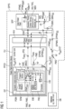
- FIGURES 1 to 5 show:
- FIGURE 1 shows a solar power plant system SPPS for energy balancing a solar power plant SPP including various components such as inverters INV, "Photo-Voltaic ⁇ PV>” generators preferably designed as PV strings PVS and measurement devices etc., as an “implementation-concept".
- inverters INV inverters
- Photo-Voltaic ⁇ PV> generators preferably designed as PV strings PVS and measurement devices etc., as an “implementation-concept”.
- the drop of performance corresponds when cumulated over a time frame in a loss of energy. As stated in the beginning of the present application there are more reasons for such energy losses, which are useful to be quantified in the course of energy balancing the solar power plant SPP.
- the depicted solar power plant system SPPS includes, besides the solar power plant SPP with the cited components INV, PVS, MDV as a central component for energy balancing the solar power plant SPP a power plant control device PPCD and moreover a database DB, which is preferably designed as a data cloud.
- the power plant control device PPCD includes a control unit CU and a power plant interface PPIF, wherein the corresponding control of the solar power plant SPP is carried out by the control unit CU via the power plant interface PPIF.
- the control unit CU includes a computer-implemented tool CIT which is implemented as a sub-unit in the control unit CU.
- the computer-implemented tool CIT is a computer-program-product which is preferably designed as an application software, called as APP, that allows, when it is implemented, to perform special tasks. So, in the present case of the control unit CU, where the computer-program-product respectively the APP is implemented, the computer-implemented tool CIT is used for energy balancing the solar power plant SPP.
- the computer-implemented tool CIT comprises a non-transitory, processor-readable storage medium STM, in which processor-readable program-instructions of a program module PGM are stored.
- This program module PGM is used for energy balancing the solar power plant SPP.
- the computer-implemented tool CIT comprises a processor PRC connected with the storage medium STM executing the processor-readable program-instructions of the program module PGM to energy balance the solar power plant SPP, wherein the program module PGM and the processor PRC form an energy balancing engine EBE for doing this energy balancing.
- FIGURE 2 shows a solar power plant system SPPS for energy balancing a solar power plant SPP including various components such as inverters INV, "Photo-Voltaic ⁇ PV>” generators preferably designed as PV strings PVS and measurement devices etc., as a “functional-unit-concept".
- inverters INV inverters
- Photo-Voltaic ⁇ PV> generators preferably designed as PV strings PVS and measurement devices etc., as a “functional-unit-concept”.
- the drop of performance corresponds again when cumulated over a time frame in a loss of energy. As stated in the beginning of the present application there are more reasons for such energy losses, which are useful to be quantified in the course of energy balancing the solar power plant SPP.
- the depicted solar power plant system SPPS includes again, besides the solar power plant SPP with the cited components INV, PVS, MDV as a central component for energy balancing the solar power plant SPP a power plant control device PPCD and moreover a database DB, which is preferably designed as a data cloud.
- the power plant control device PPCD includes a control unit CU and a power plant interface PPIF, wherein the corresponding control of the solar power plant SPP is carried out by the control unit CU via the power plant interface PPIF.
- the control unit CU does not include the computer-implemented tool CIT. Instead, the Computer-implemented tool CIT forms a functional unit FTU with the control unit CU.
- This functional unit FTU is preferably designed such that the Computer-implemented tool CIT is either loadable into the control unit CU according to the depiction in the FIGURE 2 or forms either (not depicted in the FIGURE 2 ) a cloud-based, centralized platform, e.g. a server, for the power plant control device PPCD or a decentralized platform, e.g. a server, for the power plant control device PPCD with a mutual access within the functional unit between the control unit CU and the Computer-implemented tool CIT.
- a cloud-based, centralized platform e.g. a server
- a decentralized platform e.g. a server
- the computer-implemented tool CIT is again a computer-program-product which in the case upload-functionality is again preferably designed as an application software, called as APP, that allows, when it is implemented, to perform special tasks. So, in the present case of the control unit CU, when the computer-program-product respectively the APP is uploaded, the power plant control device PPCD with uploaded computer-implemented tool CIT is used for detecting the power production degradation of the solar power plant SPP.
- the computer-implemented tool CIT comprises again a non-transitory, processor-readable storage medium STM, in which processor-readable program-instructions of a program module PGM are stored.
- This program module PGM is used for energy balancing the solar power plant SPP.
- the computer-implemented tool CIT comprises again a processor PRC connected with the storage medium STM executing the processor-readable program-instructions of the program module PGM to energy balance the solar power plant SPP, wherein the program module PGM and the processor PRC form again an energy balancing engine EBE for doing this energy balancing.
- the energy balancing for both concepts, the "implementation-concept” and the “functional-unit-concept” is generally based on various measurements MM (cf. FIGURE 3 ).
- EATP energy accounting time period
- the measurement signals IMS, PMS with the corresponding measured values SIMV, SPPMV are measured independently or time shifted from the energy balancing process itself, they can be stored meanwhile or intermediately in the database DB before they are inputted into, supplied to or retrieved from the processor PRC via the power plant interface PPIF and the control unit CU. Otherwise they are inputted directly into, supplied directly to or retrieved directly from the processor PRC via the power plant interface PPIF and the control unit CU.
- both parameter set "K” PMS and the estimated power production measurement signal "P est (t, K)" PPMS est can be stored preferably in the database DB.
- the energy balancing engine EBE formed by the processor PRC and the program module PGM is designed such that a control information CINF is generated and used to control reductions of impacts concerning the calculated energy loss E loss on the solar power plant SPP.
- the energy balancing engine EBE formed by the processor PRC and the program module PGM is designed advantageously such that the curve matching algorithm CMA (cf. FIGURE 3 ) to identify idf the at least one good matching time GMT is preferably iterative based, in which following primary steps "S1 p " to "S6 p " of the curve matching algorithm CMA (cf. FIGURE 3 ) are carried out, wherein the steps "S3 p " to "S5 p " are done iteratively.
- a first primary step “S1 p " the power production measurement signal "P(t)” PPMS with the set of power production measurement values “P(t 0 )” to “P(t n )” SPPMV and the irradiation measurement signal "I(t)” IMS with the set of irradiation measurement values "I(t 0 )” to "I(t n )” SIMV are fed to the curve matching algorithm CMA (cf. FIGURE 3 ).
- a candidate set CS GM for good matching to the recording time "[t 0 to t n ]" are set.
- a scaling factor "s" SF by solving a first optimization problem OPP1 to min s ⁇ t ⁇ candidate set P t ⁇ sI t 2 is calculated.
- time points from the candidate set for good matching CS GM are included, wherein all of the following criteria between a "P(t)"-value and a “sI(t)"-value for "t” in the recording time "[t 0 to t n ]" are satisfied
- a sixth primary step “S6 p” the at least one good matching time GMT corresponding to the candidate set CS GM is outputted after the last iteration of the fifth primary step " S5 p ".
- the energy balancing engine EBE formed by the processor PRC and the program module PGM is designed advantageously such that the robust least squares fit algorithm RLSFA (cf. FIGURE 3 ) as an advantageous form of the fitting algorithm FA to generate grt the parameter set "K” PMS with the at least one parameter "[k 0 , k 1 , ...]” PM is preferably also iterative based, in which following secondary steps “S1 s “ to "S5 s " of the robust least squares fit algorithm RLFSA (cf. FIGURE 3 ) are carried out, wherein the steps "S2 s " to "S4 s " are done iteratively.
- RLSFA robust least squares fit algorithm
- a further third secondary step “S3 s” the further parameter set "K*" PMS' is used to calculate a set of quadratic deviations SQD as [(P(t) - P est (t,K*)) 2 ... ] for all "t ⁇ good matching times". Then also in this third secondary step “S3 s " a percentage share of the times, e.g. 10%, from the good matching times corresponding to the highest values in the set of quadratic deviations SQD are eliminated.
- a historical parameter set "K” may be used to screen for partial failures of the component. If historical parameter set "K” jumped to lower values and remained at such low values until to the robust least squares fit algorithm evaluation, this means that a partial failure is present in the solar power plant during the robust least squares fit algorithm evaluation. In this case, the last parameter set "K" before the jump should be used to also estimate the energy losses due to constant partial failures, as well as intermittent failures.
Landscapes
- Engineering & Computer Science (AREA)
- Power Engineering (AREA)
- Management, Administration, Business Operations System, And Electronic Commerce (AREA)
- Supply And Distribution Of Alternating Current (AREA)
Claims (12)
- Computerimplementiertes Verfahren zum Energieausgleich von Solarkraftwerken durchErfassen (clt) für einen Energiebilanzierungszeitraum (EATP) eines Solarkraftwerks (SPP, INV, PVS, MDV), wobei über eine Aufzeichnungszeit "[t0 bis tn]" mit
 gekennzeichnet durch:a) Anpassen (mtc) des Stromerzeugungsmesssignals "P(t)" (PPMS) an das Bestrahlungsmesssignal "I(t)" (IMS) für die Aufzeichnungszeit "[t0 bis tn]" unter Verwendung eines curve-matching Algorithmus (CMA) zur Identifizierung (idf) basierend auf dem Satz von Stromerzeugungsmesswerten "P(t0)" bis "P(tn)" (SPPMV) und dem Satz von Bestrahlungsmesswerten "I(t0)" bis "I(tn)" (SIMV), die zu mindestens einer guten Anpassungszeit (GMT) erfasst (clt) werden, in der das Stromerzeugungsmesssignal "P(t)" (PPMS) und das Bestrahlungsmesssignal "I(t)" (IMS) durch einen minimalen Signalabstand (MSD) optimal übereinstimmen,b) Ausführen (rn) eines Anpassungsalgorithmus (FA) für die mindestens eine gute Anpassungszeit (GMT) und basierend <i> in Bezug auf einem mit der "guten Anpassungszeit" zusammenhängenden Teil des Stromerzeugungsmesssignals "PGMT(t)" (PPMSGMT) auf einem Teilsatz des Satzes der Stromerzeugungsmesswerte "P(t0)" bis "P(tn)" (SPPMVSS) und <ii> in Bezug auf einen mit der "guten Anpassungszeit" zusammenhängenden Teil des Bestrahlungsmesssignals "IGMT(t)" (IMSSGMT) auf einem Teilsatz des Satzes der Bestrahlungsmesswerte "I(t0)" bis "I(tn)" (SIMVSS) zur Erzeugung (grt) gemäß einem geschätzten Stromerzeugungsmesssignal "Pest(t, K)" (PPMSest), das definiert ist als eine Funktion "f(I(t), K)" mit "Pest(t, K)=f(I(t), K=[k0, k1, ...])", eines Parametersatzes "K" (PMS) mit mindestens einem Parameter "[k0, k1, ...]" (PM), wobei beim Ausführen (rn) des Anpassungsalgorithmus (FA) eine Abweichung zwischen dem Stromerzeugungsmesssignal "P(t)" (PPMS) und dem geschätzten Stromerzeugungsmesssignal "Pest(t, K)" (PPMSest) durch Abstimmung oder Änderung des Parametersatzes "K" (PMS) minimiert wird,c) Berechnen (clc) der Aufzeichnungszeit "[t0 bis tn]" basierend auf <1> dem Satz von Stromerzeugungsmesswerten "P(t0)" bis "P(tn)" (SPPMV), <2> dem Satz von Bestrahlungsmesswerten "I(t0)" bis "I(tn)" (SIMV) und <3> dem erzeugten Parametersatz "K" (PMS) mit dem mindestens einen Parameter "[k0, k1, ...]" (PM) des geschätzten Stromerzeugungsmesssignals "Pest(t, K)" (PPMSest) zur Bestimmung (dtm) eines Werts für einen Energieverlust (Eloss) durch eine integrale Berechnung (ITC) einer Leistungsdifferenz (PD)
- Computerimplementiertes Verfahren nach Anspruch 1, dadurch gekennzeichnet, dassder curve-matching Algorithmus (CMA) zur Identifizierung (idf) der mindestens einen guten Anpassungszeit (GMT) iterativ basiert ist, wobei folgende Primärschritte "S1p " bis "S6p " des curve-matching Algorithmus (CMA) durchgeführt werden, wobei die Schritte "S3p " bis "S5p " iterativ durchgeführt werden"S1p ": Einspeisen des Stromerzeugungsmesssignals "P(t)" (PPMS) mit dem Satz von Stromerzeugungsmesswerten "P(t0)" bis "P(tn)" (SPPMV) und des Bestrahlungsmesssignals "I(t)" (IMS) mit dem Satz von Bestrahlungsmesswerten "I(t0)" bis "I(tn)" (SIMV) in den curve-matching Algorithmus (CMA),"S2p": Einstellen eines Kandidatensatzes für gute Anpassung (CSGM) auf die Aufzeichnungszeit "[t0 bis tn]""S3p": Berechnen eines Skalierungsfaktors "s" (SF) durch Lösen eines ersten Optimierungsproblems (OPP1) zu
 "S4p": Einschließen von Zeitpunkten in den Kandidatensatz für gute Anpassung (CSGM), wobei alle folgenden Kriterien zwischen einem "P(t)"-Wert und einem "sI(t)"-Wert für "t" in der Aufzeichnungszeit "[t0 bis tn]" erfüllt sind- Eine Abweichung zwischen den Werten ist kleiner als ein erster Schwellwert (THV1)- Eine Variabilitätsdifferenz der Werte ist kleiner als ein zweiter Schwellwert (THV2),"S5p ": Zurückgehen zum Primärschritt "S3p ", bis der Kandidatensatz für gute Anpassung (CSGM) gemäß den Primärschritten "S4p" unverändert bleibt,"S6p ": Ausgeben der mindestens einen guten Anpassungszeit (GMT), die dem Kandidatensatz (CSGM) nach der letzten Iteration des Primärschritts "S5p " entspricht.
 - Computerimplementiertes Verfahren nach Anspruch 1 oder 2, dadurch gekennzeichnet, dassder Anpassungsalgorithmus (FA) ein robuster Kleinste-Quadrate-Anpassungsalgorithmus (RLSFA) ist zur Erzeugung (grt) des Parametersatzes "K" (PMS) mit dem mindestens einen Parameter "[k0, k1, ...]" (PM) ist iterativ basiert, wobei folgende Sekundärschritte "S1s " bis "S5s " des robusten Kleinste-Quadrate-Anpassungsalgorithmus (RLSFA) durchgeführt werden, wobei die Schritte "S2s" bis "S4s"iterativ durchgeführt werden"S1s ": Einspeisen des mit der "guten Anpassungszeit" zusammenhängenden Teils des Stromerzeugungsmesssignals "PGMT(t)" (PPMSGMT) mit dem Teilsatz des Satzes der Stromerzeugungsmesswerte "P(t0)" bis "P(tn)" (SPPMVSS) und des mit der "guten Anpassungszeit" zusammenhängenden Teils des Bestrahlungsmesssignals "IGMT(t)" (IMSGMT) auf dem Teilsatz des Satzes der Bestrahlungsmesswerte "I(t0)" bis "I(tn)" (SIMVSS) in den robusten Kleinste-Quadrate-Anpassungsalgorithmus (RLSFA),"S2s ": Berechnen eines weiteren Parametersatzes "K*" (PMS') durch Lösen eines zweiten Optimierungsproblems (OPP2) zu
 wobei Pest eine Funktion der Zeit "t" ist und der weitere Parametersatz "K*" (PMS') mit Pest(t, K *)=f(I(t), K *)" ist"S3s": Verwenden des weiteren Parametersatzes "K*" (PMS') zum Berechnen eines Satzes quadratischer Abweichungen (SQD) als f(P(t)-Pest(t,K*))2 ... ] für alle "t ∈ guten Anpassungszeiten". Eliminieren eines prozentualen Anteils der Zeiten, z. B. 10 %, aus den guten Anpassungszeiten, die den höchsten Werten im Satz quadratischer Abweichungen (SQD) entsprechen,"S4s": Übergehen zu dem Sekundärschritt "S2s ", bis eine definierte Anzahl von Iterationen, z. B. 3 Iterationen, erreicht ist,"S5s": Ausgeben des dem weiteren Parametersatz "K*" (PMS') entsprechenden Parametersatzes "K" (PMS) nach der letzten Iteration des Sekundärschritts "S4s ".
 - Computerimplementiertes Verfahren nach Anspruch 1, 2 oder 3, dadurch gekennzeichnet, dass
die Funktion "f(I(t), K)" mit K=[k0, k1, ...] das geschätzte Stromerzeugungsmesssignal "Pest(t, K)" (PPMSest) durch eine lineare Funktion "Pest(t, k0)= I(t)" oder eine quadratische Funktion "Pest(t, k0, k1)= k0 I(t) + k1 I(t)2" berechnet wird. - Computerimplementiertes Verfahren nach einem der Ansprüche 1 bis 4, dadurch gekennzeichnet, dass
eine Steuerungsinformation (CINF) erzeugt wird und zur Steuerung von Einwirkungsreduzierungen bezüglich des berechneten Energieverlustes (Eloss) auf das Solarkraftwerk (SPP) verwendet wird. - Computerimplementiertes Werkzeug (CIT), insbesondere eine Anwendungssoftware <App>, für den Energieausgleich von Solarkraftwerken, wobei für einen Energiebilanzierungszeitraum (EATP) eines Solarkraftwerks (SPP, INV, PVS, MDV), wobei über eine Aufzeichnungszeit "[t0 bis tn]" mit

gekennzeichnet durch:
ein nichtflüchtiges, prozessorlesbares Speichermedium (STM) mit prozessorlesbaren Programmanweisungen eines Programmmoduls (PGM) zum Energieausgleich von Solarkraftwerken, die in dem nichtflüchtigen, prozessorlesbaren Speichermedium (STM) gespeichert sind, und einen Prozessor (PRC), der mit dem Speichermedium (STM) verbunden ist und die prozessorlesbaren Programmanweisungen des Programmmoduls (PGM) zum Energieausgleich von Solarkraftwerken ausführt, wobei das Programmmodul (PGM) und der Prozessor (PRC) eine Energieausgleichsmaschine (EBE) bilden, um Folgendes durchzuführen:a) Anpassen (mtc) des Stromerzeugungsmesssignals "P(t)" (PPMS) an das Bestrahlungsmesssignal "I(t)" (IMS) für die Aufzeichnungszeit "[t0 bis tn]" unter Verwendung eines curve-matching Algorithmus (CMA) zur Identifizierung (idf) basierend auf dem Satz von Stromerzeugungsmesswerten "P(t0)" bis "P(tn)" (SPPMV) und dem Satz von Bestrahlungsmesswerten "I(t0)" bis "I(tn)" (SIMV), die zu mindestens einer guten Anpassungszeit (GMT) erfasst (clt) werden, in der das Stromerzeugungsmesssignal "P(t)" (PPMS) und das Bestrahlungsmesssignal "I(t)" (IMS) durch einen minimalen Signalabstand (MSD) optimal übereinstimmen,b) Ausführen (rn) eines Anpassungsalgorithmus (FA) für mindestens eine gute Anpassungszeit (GMT) und basierend <i> in Bezug auf einen mit der "guten Anpassungszeit" zusammenhängenden Teil des Stromerzeugungsmesssignals "PGMT(t)" (PPMSGMT) auf einem Teilsatz des Satzes der Stromerzeugungsmesswerte "Pi(t0)" bis "Pi(tn)" (SPPMVSS) und <ii> in Bezug auf einen mit der "guten Anpassungszeit" zusammenhängenden Teil des Bestrahlungsmesssignals "IGMT(t)" (IMSGMT) auf einem Teilsatz der Bestrahlungsmesswerte "I(t0)" bis "I(tn)" (SIMVSS zur Erzeugung (grt) gemäß einem geschätzten Stromerzeugungsmesssignal "Pest(t, K)" (PPMSest), das definiert ist als eine Funktion "f(I(t), K)" mit "Pest(t, K)=f(I(t), K=[k0, k1, ...]), eines Parametersatzes "K" (PMS) mit mindestens einem Parameter "[k0, k1, ...]" (PM), wobei beim Ausführen (rn) des Anpassungsalgorithmus (FA) eine Abweichung zwischen dem Stromerzeugungsmesssignal "P(t)" (PPMS) und dem geschätzten Stromerzeugungsmesssignal "Pest(t, K)" (PPMSest) durch Abstimmen oder Ändern des Parametersatzes "K" (PMS) minimiert wird,c) Berechnen (clc) der Aufzeichnungszeit "[t0 bis tn]" basierend auf <1> dem Satz von Stromerzeugungsmesswerten "P(t0)" bis "P(t2)" (SPPMV), <2> dem Satz von Bestrahlungsmesswerten "I(t0)" bis "I(tn)" (SIMV) und <3> dem erzeugten Parametersatz "K" (PMS) mit dem mindestens einen Parameter "[k0, k1, ...]" (PM) des geschätzten Stromerzeugungsmesssignals "Pest(t, K)" (PPMSest) zur Bestimmung (dtm) eines Werts für einen Energieverlust (Eloss) durch eine integrale Berechnung (ITC) einer Leistungsdifferenz (PD)
- Computerimplementiertes Werkzeug (CIT) nach Anspruch 6, dadurch gekennzeichnet, dassdie Energieausgleichsmaschine (EBE) so ausgelegt ist, dass der curve-matching Algorithmus (CMA) zur Identifizierung (idf) der mindestens einen guten Anpassungszeit (GMT) iterativ basiert ist, wobei folgende Primärschritte "S1p " bis "S6p " des curve-matching Algorithmus (CMA) durchgeführt werden, wobei die Schritte "S3p " bis "S5p " iterativ durchgeführt werden"S1p ": Einspeisen des Stromerzeugungsmesssignals "P(t)" (PPMS) mit dem Satz von Stromerzeugungsmesswerten "P(t0)" bis "P(tn)" (SPPMV) und des Bestrahlungsmesssignals "I(t)" (IMS) mit dem Satz von Bestrahlungsmesswerten "I(t0)" bis "I(tn)" (SIMV) in den curve-matching Algorithmus (CMA),"S2p": Einstellen eines Kandidatensatzes für gute Anpassung (CSGM) auf die Aufzeichnungszeit "[t0 bis tn]","S3p": Berechnen eines Skalierungsfaktors "s" (SF) durch Lösen eines ersten Optimierungsproblems (OPP1) zu
 "S4p": Einschließen von Zeitpunkten in den Kandidatensatz für gute Anpassung (CSGM), wobei alle folgenden Kriterien zwischen einem "P(t)"-Wert und einem "sI(t)"-Wert für "t" in der Aufzeichnungszeit "[t0 bis tn]" erfüllt sind- Eine Abweichung zwischen den Werten ist kleiner als ein erster Schwellwert (THV1)- Eine Variabilitätsdifferenz der Werte ist kleiner als ein zweiter Schwellwert (THV2),"S5p ": Zurückgehen zum Primärschritt "S3p ", bis der Kandidatensatz für gute Anpassung (CSGM) gemäß den Primärschritten "S4p" unverändert bleibt,"S6p ": Ausgeben der mindestens einen guten Anpassungszeit (GMT), die dem Kandidatensatz (CSGM) nach der letzten Iteration des Primärschritts "S5p " entspricht.
 - Computerimplementiertes Werkzeug (CIT) nach Anspruch 6 oder 7, dadurch gekennzeichnet, dassder Anpassungsalgorithmus (FA) ein robuster Kleinste-Quadrate-Anpassungsalgorithmus (RLSFA) ist und die Energieausgleichsmaschine (EBE) so ausgelegt ist, dass der Kleinste-Quadrate-Anpassungsalgorithmus (RLSFA) zur Erzeugung (grt) des Parametersatzes "K" (PMS) mit dem mindestens einen Parameter "[k0, k1, ...]" (PM) iterativ basiert ist, wobei folgende Sekundärschritte "S1s " bis "S5s " des robusten Kleinste-Quadrate-Anpassungsalgorithmus (RLSFA) durchgeführt werden, wobei die Schritte "S2s" bis "S4s" iterativ durchgeführt werden"S1s ": Einspeisen des mit der "guten Anpassungszeit" zusammenhängenden Teils des Stromerzeugungsmesssignals "PGMT(t)" (PPMSGMT) mit dem Teilsatz des Satzes der Stromerzeugungsmesswerte "P(t0)" bis "P(tn)" (SPPMVSS) und des mit der "guten Anpassungszeit" zusammenhängenden Teils des Bestrahlungsmesssignals "IGMT(t)" (IMSGMT) auf dem Teilsatz des Satzes der Bestrahlungsmesswerte "I(t0)" bis "I(tn)" (SIMVSS in den robusten Kleinste-Quadrate-Anpassungsalgorithmus (RLSFA),"S2s": Berechnen eines weiteren Parametersatzes "K*" (PMS') durch Lösen eines zweiten Optimierungsproblems (OPP2) zu
 wobei Pest eine Funktion der Zeit "t" ist und der weitere Parametersatz "K*" (PMS') mit Pest(t, K *)=f(I(t), K*)" ist"S3s": Verwenden des weiteren Parametersatzes "K*" (PMS') zum Berechnen eines Satzes quadratischer Abweichungen (SQD) als [(P(t)-Pest(t, K*))2 ... ] für alle "t ∈ guten Anpassungszeiten". Eliminieren eines prozentualen Anteils der Zeiten, z. B. 10 %, aus den guten Anpassungszeiten, die den höchsten Werten im Satz quadratischer Abweichungen (SQD) entsprechen,"S4s": Übergehen zu dem Sekundärschritt "S2s", bis eine definierte Anzahl von Iterationen, z. B. 3 Iterationen, erreicht ist,"S5s": Ausgeben des dem weiteren Parametersatz "K*" (PMS') entsprechenden Parametersatzes "K" (PMS) nach der letzten Iteration des Sekundärschritts "S4s".
 - Computerimplementiertes Werkzeug (CIT) nach Anspruch 6, 7 oder 8, dadurch gekennzeichnet, dass
die Funktion "f(I(t), K)" mit K=[k0, k1, ...] das geschätzte Stromerzeugungsmesssignal "Pest(t, K)" (PPMSest) durch eine lineare Funktion "Pest(t, k0)= I(t)" oder eine quadratische Funktion "Pest(t, k0, k1)= k0 I(t) + k1 I(t)2" berechnet wird. - Computerimplementiertes Werkzeug (CIT) nach einem der Ansprüche 1 bis 4, dadurch gekennzeichnet, dass
die Energieausgleichsmaschine (EBE) derart ausgelegt ist, dass eine Steuerungsinformation (CINF) erzeugt wird und zur Steuerung von Einwirkungsreduzierungen bezüglich des berechneten Energieverlustes (Eloss) an dem Solarkraftwerk (SPP) verwendet wird. - Kraftwerkssteuerungsvorrichtung (PPCD) zum Energieausgleich von Solarkraftwerken mit einer mit einem Solarkraftwerk (SPP, INV, PVS, MDV) verbundenen Steuereinheit (CU) zur Steuerung des Solarkraftwerks (SPP), insbesondere zum Einstellen von Sollwerten des Kraftwerks oder zur Optimierung eines Wartungsplans,
gekennzeichnet durch
ein computerimplementiertes Werkzeug (CIT) nach einem der Ansprüche 6 bis 10, das entweder als Untereinheit in der Steuereinheit (CU) implementiert ist oder mit der Steuereinheit (CU) eine Funktionseinheit (FTU) bildet, insbesondere derart, dass das computerimplementierte Werkzeug (CIT) in die Steuereinheit (CU) ladbar ist oder entweder eine cloudbasierte, zentrale Plattform für die Kraftwerkssteuerungsvorrichtung (PPCD) oder eine dezentrale Plattform für die Kraftwerkssteuerungsvorrichtung (PPCD) bildet, um das Verfahren nach einem der Ansprüche 1 bis 5 auszuführen. - Solarkraftwerkssystem (SPPS), das ein Solarkraftwerk (SPP, INV, PVS, MDV) beinhaltet, die gesteuert wird, insbesondere um Sollwerte des Kraftwerks einzustellen oder um einen Wartungsplan des Kraftwerks zu optimieren,
gekennzeichnet durch eine Kraftwerkssteuerungsvorrichtung (PPCD) zum Energieausgleich von Solarkraftwerken nach Anspruch 11, die im Zuge der Steuerung des Solarkraftwerks (SPP, INV, PVS, MDV) mit dem Solarkraftwerk (SPP, INV, PVS, MDV) verbunden und derart ausgebildet ist, dass das computerimplementierte Verfahren nach einem der Ansprüche 1 bis 5 ausgeführt wird.
Priority Applications (2)
| Application Number | Priority Date | Filing Date | Title |
|---|---|---|---|
| EP22208077.2A EP4372948B1 (de) | 2022-11-17 | 2022-11-17 | Computerimplementiertes verfahren, computerimplementiertes werkzeug und kraftwerkssteuerungsvorrichtung zum energieausgleich von solarkraftwerken und solarkraftwerkssystem |
| US18/387,575 US20240178672A1 (en) | 2022-11-17 | 2023-11-07 | Computer-implemented method, computer-implemented tool and power plant control device for energy balancing solar power plants and a solar power plant system |
Applications Claiming Priority (1)
| Application Number | Priority Date | Filing Date | Title |
|---|---|---|---|
| EP22208077.2A EP4372948B1 (de) | 2022-11-17 | 2022-11-17 | Computerimplementiertes verfahren, computerimplementiertes werkzeug und kraftwerkssteuerungsvorrichtung zum energieausgleich von solarkraftwerken und solarkraftwerkssystem |
Publications (2)
| Publication Number | Publication Date |
|---|---|
| EP4372948A1 EP4372948A1 (de) | 2024-05-22 |
| EP4372948B1 true EP4372948B1 (de) | 2025-05-14 |
Family
ID=84359200
Family Applications (1)
| Application Number | Title | Priority Date | Filing Date |
|---|---|---|---|
| EP22208077.2A Active EP4372948B1 (de) | 2022-11-17 | 2022-11-17 | Computerimplementiertes verfahren, computerimplementiertes werkzeug und kraftwerkssteuerungsvorrichtung zum energieausgleich von solarkraftwerken und solarkraftwerkssystem |
Country Status (2)
| Country | Link |
|---|---|
| US (1) | US20240178672A1 (de) |
| EP (1) | EP4372948B1 (de) |
Family Cites Families (4)
| Publication number | Priority date | Publication date | Assignee | Title |
|---|---|---|---|---|
| US10508987B2 (en) * | 2016-09-12 | 2019-12-17 | Also Energy, Inc. | System and method for remote calibration of irradiance sensors of a solar photovoltaic system |
| EP3669454B1 (de) * | 2017-08-17 | 2020-11-25 | SMA Solar Technology AG | Verfahren und vorrichtung zur erfassung einer maximalen anlagenleistung einer photovoltaikanlage |
| CA3185577A1 (en) * | 2020-07-15 | 2022-01-20 | Linda IRISH | Power balancing solar charging system |
| CN112531694B (zh) * | 2020-11-27 | 2022-05-20 | 国网重庆市电力公司电力科学研究院 | 基于数字孪生技术的交直流混合电网全域实时模拟方法 |
-
2022
- 2022-11-17 EP EP22208077.2A patent/EP4372948B1/de active Active
-
2023
- 2023-11-07 US US18/387,575 patent/US20240178672A1/en active Pending
Also Published As
| Publication number | Publication date |
|---|---|
| EP4372948A1 (de) | 2024-05-22 |
| US20240178672A1 (en) | 2024-05-30 |
Similar Documents
| Publication | Publication Date | Title |
|---|---|---|
| Williams et al. | Wind power costs expected to decrease due to technological progress | |
| JP6115764B2 (ja) | 太陽光発電システム、異常判断処理装置、異常判断処理方法、およびプログラム | |
| US6188205B1 (en) | Power system control apparatus and power system control method | |
| EP2290779A1 (de) | Vorrichtung zur regelung von energieversorgung/-bedarf und verfahren zur regelung von energieversorgung/-bedarf | |
| EP3477404A1 (de) | Parameterkonditionierungswerkzeug für das stromsystemmodell | |
| EP2527949A1 (de) | Mppt-steuergerät, steuervorrichtung für solarbatterien, solarstromerzeugungssystem, mppt-steuerungsprogramm und steuerverfahren für das mttp-steuergerät | |
| US20230258161A1 (en) | A method and an apparatus for computer-implemented prediction of power production of one or more wind turbines in a wind farm | |
| JP2012124188A (ja) | 太陽光発電量予測装置,太陽光発電量予測方法,系統電圧制御装置,系統電圧制御方法 | |
| US20210124854A1 (en) | Systems and methods for enhanced power system model parameter estimation | |
| JP2018007311A (ja) | 太陽光発電保守装置、太陽光発電保守システム、太陽光発電保守方法及びコンピュータプログラム | |
| KR102002548B1 (ko) | 영농형 태양광 발전 예측시스템 및 이를 이용한 발전량 및 수익 예측 방법 | |
| JP2012095478A (ja) | 太陽光発電の出力推定方法および出力推定装置 | |
| US20250175006A1 (en) | Network reconfiguration and effective load carrying capability quantification to enhance grid resilience | |
| JP2021114856A (ja) | 風力発電出力の予測方法及び予測装置 | |
| JP2019208350A (ja) | 太陽光発電設備の診断装置 | |
| CN119398530A (zh) | 一种考虑极端自然灾害的配电网多维规划方法以及系统 | |
| JP2016073155A (ja) | 需要予測装置、需要予測方法、及びプログラム | |
| EP4372948B1 (de) | Computerimplementiertes verfahren, computerimplementiertes werkzeug und kraftwerkssteuerungsvorrichtung zum energieausgleich von solarkraftwerken und solarkraftwerkssystem | |
| CN118539600A (zh) | 一种高速公路太阳能光伏发电控制方法及系统 | |
| EP4429070A1 (de) | Verfahren und verarbeitungssystem zur verarbeitung von daten im zusammenhang mit einem stromnetz und system mit einem stromnetz | |
| JP5380119B2 (ja) | 小規模電力系統の電源容量推定装置、その電源容量推定方法及び電源容量推定用プログラム | |
| EP3889698A1 (de) | Verfahren, computerimplementiertes werkzeug und kraftwerksteuerungsvorrichtung zur bestimmung einer leistung eines hybridkraftwerks und hybridkraftwerkssystem | |
| EP3885860B1 (de) | Verfahren, computerimplementiertes werkzeug und kraftwerkssteuerungsvorrichtung zur erkennung der verschlechterung der stromerzeugung von solarkraftwerken | |
| EP4102059A1 (de) | Schätzung einer überarbeiteten leistungskennlinie | |
| JPH0922402A (ja) | 日最大電力需要量予測方法 |
Legal Events
| Date | Code | Title | Description |
|---|---|---|---|
| PUAI | Public reference made under article 153(3) epc to a published international application that has entered the european phase |
Free format text: ORIGINAL CODE: 0009012 |
|
| STAA | Information on the status of an ep patent application or granted ep patent |
Free format text: STATUS: THE APPLICATION HAS BEEN PUBLISHED |
|
| AK | Designated contracting states |
Kind code of ref document: A1 Designated state(s): AL AT BE BG CH CY CZ DE DK EE ES FI FR GB GR HR HU IE IS IT LI LT LU LV MC ME MK MT NL NO PL PT RO RS SE SI SK SM TR |
|
| STAA | Information on the status of an ep patent application or granted ep patent |
Free format text: STATUS: REQUEST FOR EXAMINATION WAS MADE |
|
| 17P | Request for examination filed |
Effective date: 20240805 |
|
| RBV | Designated contracting states (corrected) |
Designated state(s): AL AT BE BG CH CY CZ DE DK EE ES FI FR GB GR HR HU IE IS IT LI LT LU LV MC ME MK MT NL NO PL PT RO RS SE SI SK SM TR |
|
| GRAP | Despatch of communication of intention to grant a patent |
Free format text: ORIGINAL CODE: EPIDOSNIGR1 |
|
| STAA | Information on the status of an ep patent application or granted ep patent |
Free format text: STATUS: GRANT OF PATENT IS INTENDED |
|
| INTG | Intention to grant announced |
Effective date: 20250110 |
|
| GRAS | Grant fee paid |
Free format text: ORIGINAL CODE: EPIDOSNIGR3 |
|
| GRAA | (expected) grant |
Free format text: ORIGINAL CODE: 0009210 |
|
| STAA | Information on the status of an ep patent application or granted ep patent |
Free format text: STATUS: THE PATENT HAS BEEN GRANTED |
|
| AK | Designated contracting states |
Kind code of ref document: B1 Designated state(s): AL AT BE BG CH CY CZ DE DK EE ES FI FR GB GR HR HU IE IS IT LI LT LU LV MC ME MK MT NL NO PL PT RO RS SE SI SK SM TR |
|
| REG | Reference to a national code |
Ref country code: GB Ref legal event code: FG4D |
|
| REG | Reference to a national code |
Ref country code: CH Ref legal event code: EP |
|
| REG | Reference to a national code |
Ref country code: DE Ref legal event code: R096 Ref document number: 602022014601 Country of ref document: DE |
|
| REG | Reference to a national code |
Ref country code: IE Ref legal event code: FG4D |
|
| REG | Reference to a national code |
Ref country code: NL Ref legal event code: MP Effective date: 20250514 |
|
| PG25 | Lapsed in a contracting state [announced via postgrant information from national office to epo] |
Ref country code: ES Free format text: LAPSE BECAUSE OF FAILURE TO SUBMIT A TRANSLATION OF THE DESCRIPTION OR TO PAY THE FEE WITHIN THE PRESCRIBED TIME-LIMIT Effective date: 20250514 Ref country code: PT Free format text: LAPSE BECAUSE OF FAILURE TO SUBMIT A TRANSLATION OF THE DESCRIPTION OR TO PAY THE FEE WITHIN THE PRESCRIBED TIME-LIMIT Effective date: 20250915 Ref country code: FI Free format text: LAPSE BECAUSE OF FAILURE TO SUBMIT A TRANSLATION OF THE DESCRIPTION OR TO PAY THE FEE WITHIN THE PRESCRIBED TIME-LIMIT Effective date: 20250514 |
|
| REG | Reference to a national code |
Ref country code: LT Ref legal event code: MG9D |
|
| PG25 | Lapsed in a contracting state [announced via postgrant information from national office to epo] |
Ref country code: NO Free format text: LAPSE BECAUSE OF FAILURE TO SUBMIT A TRANSLATION OF THE DESCRIPTION OR TO PAY THE FEE WITHIN THE PRESCRIBED TIME-LIMIT Effective date: 20250814 Ref country code: GR Free format text: LAPSE BECAUSE OF FAILURE TO SUBMIT A TRANSLATION OF THE DESCRIPTION OR TO PAY THE FEE WITHIN THE PRESCRIBED TIME-LIMIT Effective date: 20250815 |
|
| PG25 | Lapsed in a contracting state [announced via postgrant information from national office to epo] |
Ref country code: NL Free format text: LAPSE BECAUSE OF FAILURE TO SUBMIT A TRANSLATION OF THE DESCRIPTION OR TO PAY THE FEE WITHIN THE PRESCRIBED TIME-LIMIT Effective date: 20250514 Ref country code: PL Free format text: LAPSE BECAUSE OF FAILURE TO SUBMIT A TRANSLATION OF THE DESCRIPTION OR TO PAY THE FEE WITHIN THE PRESCRIBED TIME-LIMIT Effective date: 20250514 |
|
| REG | Reference to a national code |
Ref country code: AT Ref legal event code: MK05 Ref document number: 1795659 Country of ref document: AT Kind code of ref document: T Effective date: 20250514 |
|
| PG25 | Lapsed in a contracting state [announced via postgrant information from national office to epo] |
Ref country code: BG Free format text: LAPSE BECAUSE OF FAILURE TO SUBMIT A TRANSLATION OF THE DESCRIPTION OR TO PAY THE FEE WITHIN THE PRESCRIBED TIME-LIMIT Effective date: 20250514 |
|
| PG25 | Lapsed in a contracting state [announced via postgrant information from national office to epo] |
Ref country code: HR Free format text: LAPSE BECAUSE OF FAILURE TO SUBMIT A TRANSLATION OF THE DESCRIPTION OR TO PAY THE FEE WITHIN THE PRESCRIBED TIME-LIMIT Effective date: 20250514 |
|
| PG25 | Lapsed in a contracting state [announced via postgrant information from national office to epo] |
Ref country code: AT Free format text: LAPSE BECAUSE OF FAILURE TO SUBMIT A TRANSLATION OF THE DESCRIPTION OR TO PAY THE FEE WITHIN THE PRESCRIBED TIME-LIMIT Effective date: 20250514 |
|
| PG25 | Lapsed in a contracting state [announced via postgrant information from national office to epo] |
Ref country code: RS Free format text: LAPSE BECAUSE OF FAILURE TO SUBMIT A TRANSLATION OF THE DESCRIPTION OR TO PAY THE FEE WITHIN THE PRESCRIBED TIME-LIMIT Effective date: 20250814 |
|
| PG25 | Lapsed in a contracting state [announced via postgrant information from national office to epo] |
Ref country code: IS Free format text: LAPSE BECAUSE OF FAILURE TO SUBMIT A TRANSLATION OF THE DESCRIPTION OR TO PAY THE FEE WITHIN THE PRESCRIBED TIME-LIMIT Effective date: 20250914 |
|
| PG25 | Lapsed in a contracting state [announced via postgrant information from national office to epo] |
Ref country code: LV Free format text: LAPSE BECAUSE OF FAILURE TO SUBMIT A TRANSLATION OF THE DESCRIPTION OR TO PAY THE FEE WITHIN THE PRESCRIBED TIME-LIMIT Effective date: 20250514 |
|
| PG25 | Lapsed in a contracting state [announced via postgrant information from national office to epo] |
Ref country code: DK Free format text: LAPSE BECAUSE OF FAILURE TO SUBMIT A TRANSLATION OF THE DESCRIPTION OR TO PAY THE FEE WITHIN THE PRESCRIBED TIME-LIMIT Effective date: 20250514 Ref country code: SM Free format text: LAPSE BECAUSE OF FAILURE TO SUBMIT A TRANSLATION OF THE DESCRIPTION OR TO PAY THE FEE WITHIN THE PRESCRIBED TIME-LIMIT Effective date: 20250514 |
|
| PG25 | Lapsed in a contracting state [announced via postgrant information from national office to epo] |
Ref country code: CZ Free format text: LAPSE BECAUSE OF FAILURE TO SUBMIT A TRANSLATION OF THE DESCRIPTION OR TO PAY THE FEE WITHIN THE PRESCRIBED TIME-LIMIT Effective date: 20250514 |
|
| PG25 | Lapsed in a contracting state [announced via postgrant information from national office to epo] |
Ref country code: EE Free format text: LAPSE BECAUSE OF FAILURE TO SUBMIT A TRANSLATION OF THE DESCRIPTION OR TO PAY THE FEE WITHIN THE PRESCRIBED TIME-LIMIT Effective date: 20250514 |
|
| PG25 | Lapsed in a contracting state [announced via postgrant information from national office to epo] |
Ref country code: SK Free format text: LAPSE BECAUSE OF FAILURE TO SUBMIT A TRANSLATION OF THE DESCRIPTION OR TO PAY THE FEE WITHIN THE PRESCRIBED TIME-LIMIT Effective date: 20250514 |
|
| PG25 | Lapsed in a contracting state [announced via postgrant information from national office to epo] |
Ref country code: IT Free format text: LAPSE BECAUSE OF FAILURE TO SUBMIT A TRANSLATION OF THE DESCRIPTION OR TO PAY THE FEE WITHIN THE PRESCRIBED TIME-LIMIT Effective date: 20250514 |
|
| REG | Reference to a national code |
Ref country code: DE Ref legal event code: R097 Ref document number: 602022014601 Country of ref document: DE |
|
| PG25 | Lapsed in a contracting state [announced via postgrant information from national office to epo] |
Ref country code: RO Free format text: LAPSE BECAUSE OF FAILURE TO SUBMIT A TRANSLATION OF THE DESCRIPTION OR TO PAY THE FEE WITHIN THE PRESCRIBED TIME-LIMIT Effective date: 20250514 |
|
| PLBE | No opposition filed within time limit |
Free format text: ORIGINAL CODE: 0009261 |
|
| STAA | Information on the status of an ep patent application or granted ep patent |
Free format text: STATUS: NO OPPOSITION FILED WITHIN TIME LIMIT |
|
| REG | Reference to a national code |
Ref country code: CH Ref legal event code: L10 Free format text: ST27 STATUS EVENT CODE: U-0-0-L10-L00 (AS PROVIDED BY THE NATIONAL OFFICE) Effective date: 20260325 |
|
| PGFP | Annual fee paid to national office [announced via postgrant information from national office to epo] |
Ref country code: DE Payment date: 20260119 Year of fee payment: 4 |
|
| 26N | No opposition filed |
Effective date: 20260217 |