EP4373103A1 - Signalverarbeitungsvorrichtung und signalverarbeitungsverfahren - Google Patents
Signalverarbeitungsvorrichtung und signalverarbeitungsverfahren Download PDFInfo
- Publication number
- EP4373103A1 EP4373103A1 EP24153750.5A EP24153750A EP4373103A1 EP 4373103 A1 EP4373103 A1 EP 4373103A1 EP 24153750 A EP24153750 A EP 24153750A EP 4373103 A1 EP4373103 A1 EP 4373103A1
- Authority
- EP
- European Patent Office
- Prior art keywords
- bit
- bits
- data
- packet
- signal line
- Prior art date
- Legal status (The legal status is an assumption and is not a legal conclusion. Google has not performed a legal analysis and makes no representation as to the accuracy of the status listed.)
- Withdrawn
Links
Images


Classifications
-
- H—ELECTRICITY
- H04—ELECTRIC COMMUNICATION TECHNIQUE
- H04N—PICTORIAL COMMUNICATION, e.g. TELEVISION
- H04N21/00—Selective content distribution, e.g. interactive television or video on demand [VOD]
- H04N21/60—Network structure or processes for video distribution between server and client or between remote clients; Control signalling between clients, server and network components; Transmission of management data between server and client, e.g. sending from server to client commands for recording incoming content stream; Communication details between server and client
- H04N21/61—Network physical structure; Signal processing
- H04N21/6106—Network physical structure; Signal processing specially adapted to the downstream path of the transmission network
- H04N21/6118—Network physical structure; Signal processing specially adapted to the downstream path of the transmission network involving cable transmission, e.g. using a cable modem
-
- H—ELECTRICITY
- H04—ELECTRIC COMMUNICATION TECHNIQUE
- H04N—PICTORIAL COMMUNICATION, e.g. TELEVISION
- H04N21/00—Selective content distribution, e.g. interactive television or video on demand [VOD]
- H04N21/40—Client devices specifically adapted for the reception of or interaction with content, e.g. set-top-box [STB]; Operations thereof
- H04N21/43—Processing of content or additional data, e.g. demultiplexing additional data from a digital video stream; Elementary client operations, e.g. monitoring of home network or synchronising decoder's clock; Client middleware
- H04N21/438—Interfacing the downstream path of the transmission network originating from a server, e.g. retrieving encoded video stream packets from an IP network
- H04N21/4382—Demodulation or channel decoding, e.g. QPSK demodulation
-
- H—ELECTRICITY
- H04—ELECTRIC COMMUNICATION TECHNIQUE
- H04N—PICTORIAL COMMUNICATION, e.g. TELEVISION
- H04N21/00—Selective content distribution, e.g. interactive television or video on demand [VOD]
- H04N21/40—Client devices specifically adapted for the reception of or interaction with content, e.g. set-top-box [STB]; Operations thereof
- H04N21/41—Structure of client; Structure of client peripherals
- H04N21/426—Internal components of the client ; Characteristics thereof
-
- H—ELECTRICITY
- H04—ELECTRIC COMMUNICATION TECHNIQUE
- H04L—TRANSMISSION OF DIGITAL INFORMATION, e.g. TELEGRAPHIC COMMUNICATION
- H04L1/00—Arrangements for detecting or preventing errors in the information received
- H04L1/0001—Systems modifying transmission characteristics according to link quality, e.g. power backoff
- H04L1/0006—Systems modifying transmission characteristics according to link quality, e.g. power backoff by adapting the transmission format
-
- H—ELECTRICITY
- H04—ELECTRIC COMMUNICATION TECHNIQUE
- H04L—TRANSMISSION OF DIGITAL INFORMATION, e.g. TELEGRAPHIC COMMUNICATION
- H04L1/00—Arrangements for detecting or preventing errors in the information received
- H04L1/0078—Avoidance of errors by organising the transmitted data in a format specifically designed to deal with errors, e.g. location
- H04L1/0083—Formatting with frames or packets; Protocol or part of protocol for error control
-
- H—ELECTRICITY
- H04—ELECTRIC COMMUNICATION TECHNIQUE
- H04L—TRANSMISSION OF DIGITAL INFORMATION, e.g. TELEGRAPHIC COMMUNICATION
- H04L12/00—Data switching networks
- H04L12/54—Store-and-forward switching systems
- H04L12/56—Packet switching systems
- H04L12/5601—Transfer mode dependent, e.g. ATM
-
- H—ELECTRICITY
- H04—ELECTRIC COMMUNICATION TECHNIQUE
- H04L—TRANSMISSION OF DIGITAL INFORMATION, e.g. TELEGRAPHIC COMMUNICATION
- H04L25/00—Baseband systems
- H04L25/02—Details ; arrangements for supplying electrical power along data transmission lines
-
- H—ELECTRICITY
- H04—ELECTRIC COMMUNICATION TECHNIQUE
- H04L—TRANSMISSION OF DIGITAL INFORMATION, e.g. TELEGRAPHIC COMMUNICATION
- H04L25/00—Baseband systems
- H04L25/02—Details ; arrangements for supplying electrical power along data transmission lines
- H04L25/14—Channel dividing arrangements, i.e. in which a single bit stream is divided between several baseband channels and reassembled at the receiver
-
- H—ELECTRICITY
- H04—ELECTRIC COMMUNICATION TECHNIQUE
- H04L—TRANSMISSION OF DIGITAL INFORMATION, e.g. TELEGRAPHIC COMMUNICATION
- H04L65/00—Network arrangements, protocols or services for supporting real-time applications in data packet communication
- H04L65/60—Network streaming of media packets
-
- H—ELECTRICITY
- H04—ELECTRIC COMMUNICATION TECHNIQUE
- H04L—TRANSMISSION OF DIGITAL INFORMATION, e.g. TELEGRAPHIC COMMUNICATION
- H04L7/00—Arrangements for synchronising receiver with transmitter
- H04L7/0008—Synchronisation information channels, e.g. clock distribution lines
-
- H—ELECTRICITY
- H04—ELECTRIC COMMUNICATION TECHNIQUE
- H04N—PICTORIAL COMMUNICATION, e.g. TELEVISION
- H04N21/00—Selective content distribution, e.g. interactive television or video on demand [VOD]
- H04N21/40—Client devices specifically adapted for the reception of or interaction with content, e.g. set-top-box [STB]; Operations thereof
- H04N21/41—Structure of client; Structure of client peripherals
- H04N21/426—Internal components of the client ; Characteristics thereof
- H04N21/42607—Internal components of the client ; Characteristics thereof for processing the incoming bitstream
-
- H—ELECTRICITY
- H04—ELECTRIC COMMUNICATION TECHNIQUE
- H04N—PICTORIAL COMMUNICATION, e.g. TELEVISION
- H04N21/00—Selective content distribution, e.g. interactive television or video on demand [VOD]
- H04N21/40—Client devices specifically adapted for the reception of or interaction with content, e.g. set-top-box [STB]; Operations thereof
- H04N21/43—Processing of content or additional data, e.g. demultiplexing additional data from a digital video stream; Elementary client operations, e.g. monitoring of home network or synchronising decoder's clock; Client middleware
- H04N21/4302—Content synchronisation processes, e.g. decoder synchronisation
-
- H—ELECTRICITY
- H04—ELECTRIC COMMUNICATION TECHNIQUE
- H04N—PICTORIAL COMMUNICATION, e.g. TELEVISION
- H04N21/00—Selective content distribution, e.g. interactive television or video on demand [VOD]
- H04N21/40—Client devices specifically adapted for the reception of or interaction with content, e.g. set-top-box [STB]; Operations thereof
- H04N21/43—Processing of content or additional data, e.g. demultiplexing additional data from a digital video stream; Elementary client operations, e.g. monitoring of home network or synchronising decoder's clock; Client middleware
- H04N21/434—Disassembling of a multiplex stream, e.g. demultiplexing audio and video streams, extraction of additional data from a video stream; Remultiplexing of multiplex streams; Extraction or processing of SI; Disassembling of packetised elementary stream
-
- H—ELECTRICITY
- H04—ELECTRIC COMMUNICATION TECHNIQUE
- H04N—PICTORIAL COMMUNICATION, e.g. TELEVISION
- H04N21/00—Selective content distribution, e.g. interactive television or video on demand [VOD]
- H04N21/40—Client devices specifically adapted for the reception of or interaction with content, e.g. set-top-box [STB]; Operations thereof
- H04N21/43—Processing of content or additional data, e.g. demultiplexing additional data from a digital video stream; Elementary client operations, e.g. monitoring of home network or synchronising decoder's clock; Client middleware
- H04N21/44—Processing of video elementary streams, e.g. splicing a video clip retrieved from local storage with an incoming video stream or rendering scenes according to encoded video stream scene graphs
-
- H—ELECTRICITY
- H04—ELECTRIC COMMUNICATION TECHNIQUE
- H04N—PICTORIAL COMMUNICATION, e.g. TELEVISION
- H04N21/00—Selective content distribution, e.g. interactive television or video on demand [VOD]
- H04N21/40—Client devices specifically adapted for the reception of or interaction with content, e.g. set-top-box [STB]; Operations thereof
- H04N21/43—Processing of content or additional data, e.g. demultiplexing additional data from a digital video stream; Elementary client operations, e.g. monitoring of home network or synchronising decoder's clock; Client middleware
- H04N21/442—Monitoring of processes or resources, e.g. detecting the failure of a recording device, monitoring the downstream bandwidth, the number of times a movie has been viewed, the storage space available from the internal hard disk
- H04N21/4425—Monitoring of client processing errors or hardware failure
-
- H—ELECTRICITY
- H04—ELECTRIC COMMUNICATION TECHNIQUE
- H04N—PICTORIAL COMMUNICATION, e.g. TELEVISION
- H04N7/00—Television systems
- H04N7/10—Adaptations for transmission by electrical cable
-
- H—ELECTRICITY
- H04—ELECTRIC COMMUNICATION TECHNIQUE
- H04L—TRANSMISSION OF DIGITAL INFORMATION, e.g. TELEGRAPHIC COMMUNICATION
- H04L12/00—Data switching networks
- H04L12/54—Store-and-forward switching systems
- H04L12/56—Packet switching systems
- H04L12/5601—Transfer mode dependent, e.g. ATM
- H04L2012/5638—Services, e.g. multimedia, GOS, QOS
Definitions
- the present technology relates to a signal processing device and a signal processing method that can be applied to a reception device that transmits large-capacity high-speed digital data.
- an image (moving image) or the like is encoded by a predetermined encoding method such as Moving Picture Experts Group (MPEG) or the like, and broadcast waves including a TS including a Transport Stream (TS) packet in which encoded data obtained as a result of encoding is disposed in a payload are transmitted.
- MPEG Moving Picture Experts Group
- TS Transport Stream
- the broadcast waves are modulated (for example, as an example, a case of BS digital satellite broadcasting, TC8PSK modulation system and ISDB-S broadcasting system, a case of cable television broadcasting, 64-QAM modulation system and ISDB-C broadcasting system) using carrier waves by a transmitter so as to transmit the TS from the transmitter to each receiver.
- modulated for example, as an example, a case of BS digital satellite broadcasting, TC8PSK modulation system and ISDB-S broadcasting system, a case of cable television broadcasting, 64-QAM modulation system and ISDB-C broadcasting system
- a multiplex frame structure of current BS/CS digital broadcasting includes 48 slots per frame, and it is possible to multiplex a plurality of channels by dividing 48 slots.
- a multiplex frame structure of a current cable television is referred to as Transport Streams Multiplexing Frame (TSMF), and the TSMF structure includes 53 slots per frame including one header slot and 52 TS arrangement slots.
- TSMF Transport Streams Multiplexing Frame
- a plurality of channels can be multiplexed by dividing 52 slots.
- IP Internet Protocol
- TLV packet variable length packet
- This advanced BS broadcasting using the TLV packet is referred to as a broadcasting system ISDB-S3, and one frame includes 120 slots. By dividing the 120 slots, three channels can be multiplexed at the maximum in a case of 4K broadcasting, and one channel can be multiplexed at the maximum in a case of 8K broadcasting.
- a service for directly transmitting broadcast waves from a broadcast satellite to a receiver in each home and a service for retransmitting broadcast waves by using a cable television network have been considered.
- the receiver in a case where the broadcast waves are directly received in homes, it is sufficient that the receiver be replaced with a receiver that can receive carrier waves (broadcast wave) modulated to the TLV packet of the advanced BS.
- carrier waves carrier waves
- Patent Documents 1 and 2 a technology has been proposed that transmits large-capacity digital data by using a currently-used system of the cable television network as reducing cost as much as possible.
- This system is a system that receives a carrier wave obtained by modulating the TLV packet of the advanced BS transmitted from the broadcast satellite by a cable television station once and converts the carrier waves into a broadcasting system (ISDB-C) that is a fixed length TS packet according to a cable television transmission path that is the existing facility so as to perform retransmission.
- a packet obtained by converting the variable length TLV packet into the fixed length TS packet can be referred to as a divided TLV packet so that the packet can be distinguished from a normal fixed length TS packet.
- this system divides the large-capacity digital data into the plurality of carrier waves by using the TSMF and performs frequency multiplex transmission, and the frequency division multiplexing is performed by using a combination of 64-QAM or 256-QAM modulation systems of the ISDB-C broadcasting system that is employed for cable television retransmission of current digital broadcasting.
- frequency information of the carrier wave and information regarding a synthesis order that is a divided order are acquired from the TSMF as information necessary for synthesis from the signal obtained by demodulating each carrier wave, and the information are synchronized and synthesized to reproduce 4K and 8K broadcast signals.
- the technology described is premised on a unit that selects a frequency of a broadcast wave (carrier wave) of large-capacity/high-speed digital data such as 4K or 8K broadcast transmitted by a broadcast satellite by a tuner, executes demodulation processing as a variable length TLV packet, and transmits the data to a processing unit that executes demux (demultiplexing) processing and decoding processing at the subsequent stage.
- a broadcast wave carrier wave
- demux demultiplexing
- the technology is premised on a unit that converts a variable length TLV packet transmitted by a broadcast satellite into a fixed length TS packet (divided TLV) by a cable television station, divides large-capacity data so as to reduce a transmission capacity, performs frequency multiplexing to the existing ISDB-C broadcasting system using the plurality of carrier waves and retransmits the data, selects a frequency of each carrier wave that has been transmitted by each tuner, executes demodulation processing as a fixed length TS packet (divided TLV) divided from the variable length TLV packet, and transmits the data to a processing unit that executes demux processing and decoding processing at the subsequent stage.
- a unit that converts a variable length TLV packet transmitted by a broadcast satellite into a fixed length TS packet (divided TLV) by a cable television station, divides large-capacity data so as to reduce a transmission capacity, performs frequency multiplexing to the existing ISDB-C broadcasting system using the plurality of carrier waves and
- the unit that executes the demodulation processing as the variable length TLV packet of the large-capacity/high-speed digital data and the unit that transmits the large-capacity/high-speed digital data obtained by demodulating a plurality of fixed length TS packets (divided TLV) divided from the plurality of variable length TLV packets and returns and synthesizes the demodulated packets to the large-capacity/high-speed digital data from the demodulation processing unit to the processing unit that executes demux processing and decoding processing at the subsequent stage are not specifically disclosed in the documents described above.
- frequencies of clocks and data are increased in serial transmission. If a physical distance between the demodulation processing unit and the processing unit is long, effects of a parasitic inductor, a parasitic capacitor capacitance, and a parasitic resistance of a wiring line coupling between the demodulation processing unit and the processing unit deforms an output waveform of the large-capacity/high-speed digital data from the demodulation processing unit, generates a delay, and deforms a waveform. Therefore, the processing unit cannot execute processing.
- ringing occurs in the output waveform and causes spurious, and the spurious affects surroundings of a tuner circuit or the like that selects a frequency of a carrier wave as a noise (Electromagnetic interference "EMI"). This deteriorates a quality of the signal.
- EMI Electromagnetic interference
- an object of the present technology is to provide a signal processing device and a signal processing method that can present deformation of a waveform and prevent occurrence of spurious in a case where large-capacity/high-speed digital data is transmitted from a demodulation processing unit to a processing unit that executes demux processing and decoding processing at the subsequent stage.
- the present technology is a signal processing device including a demodulation processing unit that executes demodulation processing, a processing unit that executes demux processing, and a sync signal line, a valid signal line, a clock signal line, and a data signal line disposed between the demodulation processing unit and the processing unit, in which a fixed length packet and a variable length packet are transmitted between the demodulation processing unit and the processing unit by using the sync signal line, the valid signal line, the clock signal line, and the data signal line. Furthermore, the present technology is a signal processing method including
- One to eight data signal lines are wired, and serial transmission or parallel transmission according to the number of wired signal lines can be performed.
- a frequency is high, and an effect of a parasitic element of the wiring line is easily received in a case of serial transmission.
- serial transmission it is possible to lower a transmission rate of transmission data, and the effect of the parasitic element can be reduced.
- the demodulation processing unit that performs synthesis includes six terminals.
- eight terminals for parallel output transmission are included, six terminals are used for input, and two terminals are used for two-bit parallel output. It is possible to use all the eight terminals for parallel output.
- an effect of a parasitic element of a wiring line can be reduced. It is possible to reliably transmit large-capacity/high-speed digital data from a demodulation processing unit to a processing unit that executes demux processing and decoding processing at the subsequent stage. In addition, it is possible to secure an area of the substrate and reduce the number of terminals of the processing unit. Note that the effects described herein are not necessarily limited and that the effect may be any effects described in the present technology or an effect different from the above effects. Furthermore, the content of the present technology is not interpreted as limiting the content on the basis of the effects indicated in the following description.
- Fig. 1 is a diagram illustrating a TSMF structure which is a multiplex frame structure of a cable television.
- the TSMF structure includes 53 slots per frame, and 53 slots include a single header slot and 52 TS arrangement slots. A plurality of channels can be multiplexed by dividing 52 slots.
- ATSMF header includes information such as information regarding a position (slot) of each TS in synchronous data (0 ⁇ 47) and a frame structure "fixed length (188 bytes)", a transmission multiplexing signal (Transmission and Multiplexing Configuration and Control: TMCC), or the like.
- TMCC Transmission and Multiplexing Configuration and Control
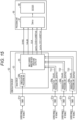
- Fig. 2 illustrates an example of a reception system that receives broadcast waves (carrier wave) of large-capacity/high-speed digital data such as 4K or 8K broadcasting transmitted by a broadcast satellite.
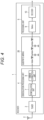
- the reception system includes an antenna 2, a receiver 1, and a display 6.
- the receiver 1 includes a tuner 3, a demodulation processing unit 4, and a processing unit 5.
- the demodulation processing unit 4 includes a demodulation unit 7 and an error correction unit 8.
- the processing unit 5 includes a demultiplexing unit (Demux) 9 and a decoder 10.
- the antenna 2 receives, for example, digital broadcast waves of a TLV system transmitted from a transmitter and supplies a reception signal obtained as a result to the receiver 1.
- the receiver 1 restores and processes the TLV from the reception signal from the antenna 2, extracts a video and sound, and outputs the extracted video and sound to the display 6.
- the error correction unit 8 corrects an error in a demodulation signal from the demodulation unit 7 and supplies a signal such as a TLV obtained as a result to the processing unit 5.
- the processing unit 5 can include, for example, a System-on-a-chip (SOC).
- SOC System-on-a-chip
- the processing unit 5 executes demux processing, for example, processing for dividing moving image content into a video part, a sound part, a subtitle part, or the like.
- a sync signal, a valid signal, a data signal, and a clock signal that are output signals output from the demodulation processing unit 4 are supplied to the processing unit 5.
- the demultiplexing unit 9 of the processing unit 5 separates, for example, video data and sound data included in the data signal, and the decoder decodes the video data into a video signal or decodes the sound data into a sound signal so as to generate video and sound signals and output the signals to the display 6.
- Fig. 3 is a diagram illustrating a configuration of a system regarding digital cable television broadcasting.
- the system includes an antenna 11 that receives satellite broadcasting, a transmitter 12, and a receiver 1.
- the satellite broadcasting received by the antenna 11 is supplied to the transmitter (cable television station) 12.
- the transmitter 12 includes a satellite tuner 13 and a cable retransmission conversion unit 14.
- the transmitter 12 is a device on a side of a broadcast station that performs digital cable television broadcasting.
- the transmitter 12 converts broadcast waves of the satellite broadcasting received by the antenna 11 into broadcast waves of digital cable television broadcasting and transmits the converted broadcast wave to the side of the receiver through a transmission path 15 of a cable television.
- the receiver 1 has a configuration similar to that of the receiver illustrated in Fig. 2 . (Therefore, similar reference numeral is applied, and description thereof is omitted). However, the tuner 3 of the receiver 1 illustrated in Fig. 3 receives and processes the digital broadcast waves transmitted through the transmission path 15.
- the satellite broadcasting is broadcasted as digital broadcast waves of the TLV system and received by the antenna 11.
- the transmitter 12 converts the digital broadcast waves of the TLV system into the broadcast wave of the digital cable television broadcasting, for example, a fixed length TS packet (divided TLV) and transmits the converted packet. This indicates a case where cable retransmission is performed by using an existing ISDB-C standard using the plurality of carrier waves.
- Fig. 4 is a diagram in which an equivalent circuit of a substrate wiring 20 is provided between the demodulation processing unit 4 and the processing unit 5 in a case where the large-capacity/high-speed digital data is transmitted from the demodulation processing unit 4 to the processing unit 5 that executes demux processing and decoding processing at the subsequent stage.
- a parasitic element such as a parasitic resistance (R), a parasitic inductor (L), or a parasitic capacitor capacitance (C) is added to the wiring line.
- ringing occurs in the output waveform.
- the ringing generates spurious, the generated spurious affects around a tuner circuit or the like that selects a frequency of a carrier wave as a noise (EMI), and a quality of a signal is deteriorated.
- An ideal waveform in Fig. 5A is deformed as illustrated in Fig. 5B
- the ringing occurs in the output waveform as illustrated in Fig. 5C .
- the waveform input to the processing unit 5 is deformed by the effect of the parasitic element, and a voltage does not increase to a threshold at which high level/low level of the processing unit 5 is recognized.
- the ringing occurs in the waveform, and the noise is generated in the waveform.
- Fig. 6 is a diagram for explaining signal lines provided between the demodulation processing unit 4 and the processing unit 5.
- the demodulation processing unit 4 can be an LSI that executes demodulation processing.
- the processing unit 5 can be an LSI that executes the demux processing. It is necessary for the demodulation processing unit 4 to output data so that the processing unit 5 at the subsequent stage can process the data (condition required by processing unit 5 is satisfied).
- the demodulation processing unit 4 can supply the demodulated data while satisfying the condition required by the processing unit 5.
- the demodulation processing unit 4 and the processing unit 5 are formed as different LSIs will be described as an example.
- a signal line that transmits a sync (SYNC) signal
- the data signal lines include one to eight signal lines in correspondence with one bit to eight bits.
- a single data signal line is included, and eight eight-bit data signal lines are included.
- data is not limited to eight-bit data and may be data having any bits, and signal lines depending on the bit depth are wired.
- the sync signal, the valid signal, and the clock signal can be controlled according to the number of data signal lines (bit depth transmitted in one cycle of clock signal).
- Fig. 7 is a diagram in which an even-numbered bit and an odd-numbered bit are allocated to outputs of DATA in a case of two-bit parallel transmission.
- Each bit of data is output from the demodulation processing unit 4 at the rising or falling edge of the clock from a MSB to a LSB in order or from the LSB to the MSB in order, and the processing unit 5 receives (latch) the data at the rising or falling edge of the clock.
- the two bits are output by using two bits of eight parallel outputs, and an output terminal of other data may be used. Furthermore, a bit configuration of two bits may have an allocation as illustrated in Fig. 8.
- Fig. 8 is a timing chart of data output from each data line in a case of the two-bit parallel transmission.
- one-bit signal line that transmits error information indicating occurrence of an error may be further included.
- the signal line illustrated here is an example, and a signal line that transmits other signal may be naturally provided between the demodulation processing unit 4 and the processing unit 5.
- a Low voltage differential signaling (LVDS) signal is used for an output interface.
- the LVDS signal can shorten a rising time and is suitable for increasing the speed. Furthermore, since positive and negative signals are simultaneously output, the signals are symmetrical, and there is an advantage that the noise (EMI) hardly occurs.
- EMI noise
- Table 1 is a diagram for explaining a certain synchronous byte at a head of a head region of each packet.
- variable length TLV packet a variable length TS packet
- TS packet a fixed length TS packet (divided TLV).
- a synchronous byte is allocated to the head of the header region of the packet to constantly synchronize the plurality of packets.
- Tables 2 and 3 are tables indicating an example of two-bit data in a case of the two-bit parallel transmission.
- Fig. 8A is a case where each of even-numbered bits and each of odd-numbered bits are simultaneously transmitted from a Most Significant Bit (MSB) to a Least Significant Bit (LSB) in order.
- MSB Most Significant Bit
- LSB Least Significant Bit
- variable length TLV packet since bits are transmitted from a sixth bit that is the MSB of the even-numbered bits, "1" in the sixth bit is transmitted, and “1" in the fourth bit is transmitted next. This operation is repeated until “1" in the zeroth bit is transmitted.
- bits are transmitted from the seventh bit that is the MSB of the odd-numbered bits, "0" in the seventh bit is transmitted, and "1" in the fifth bit is transmitted next. This operation is repeated until “1" in the first bit is transmitted.
- bits are transmitted from the seventh bit that is the MSB of the odd-numbered bits, "0" in the seventh bit is transmitted, "0" in the fifth bit is transmitted next. This operation is repeated until “1" in the first bit is transmitted.
- Fig. 8B is a case where the even-numbered bit and the odd-numbered bit are simultaneously transmitted from the LSB to the MSB in order.
- Fig. 8C is a case where the bits from the fourth bit to the seventh bit and from the zeroth bit to the third bit are simultaneously transmitted from the MSB to the LSB in order.
- variable length TLV packet since bits are transmitted from the seventh bit that is the MSB of bits from the fourth bit to the seventh bit, "0" in the seventh bit is transmitted, and "1" in the sixth bit is transmitted next. This operation is repeated until “1" in the fourth bit is transmitted.
- bits are transmitted from the third bit that is the MSB of bits from the zeroth bit to the third bit, "1" in the third bit is transmitted, and “1" in the second bit is transmitted next. This operation is repeated until “1" in the zeroth bit is transmitted.
- bits are transmitted from the third bit that is the MSB of bits from the zeroth bit to the third bit, "0" in the third bit is transmitted, and "1" in the second bit is transmitted next. This operation is repeated until “1" in the zeroth bit is transmitted.
- Fig. 8D is a case where the bits from the fourth bit to the seventh bit and from the zeroth bit to the third bit are simultaneously transmitted from the LSB to the MSB in order. This is a case where bits are transmitted in the reverse order of the transmission from the MSB to the LSB and is obvious. Therefore, description thereof is omitted here.
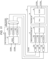
- Fig. 11 is a diagram illustrating an example of a system for dividing the large-capacity digital data into the plurality of carrier waves by using the TSMF and performing frequency multiplex transmission, and a cable television station 21, a cable television transmission path 24, and a receiver 31 are included.
- Variable length TLV packet data (8K signal) and fixed length packet TS data (HD signal) are supplied to the cable television station 21, and the supplied data is multiplexed by a division multiplexing circuit 22.
- the cable television station 21 includes a 256-QAM modulation circuit 23a, a 256-QAM modulation circuit 23b, and a 64-QAM modulation circuit 23c.
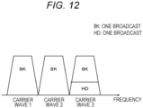
- a plurality of tuners 32a, 32b, and 32c selects an RF signal that is each carrier wave on which frequency division has been performed as illustrated in Fig. 12 and converts the frequency of the RF signal into an IF signal.
- Fig. 12 illustrates positions of three carrier waves with respect to the frequency and illustrates a case where 8K broadcasting (one broadcast) and HD broadcasting (one broadcast) are frequency-multiplexed.
- a demodulation processing unit 33 includes 256-QAM demodulation circuits 35a and 35b and a 64-QAM demodulation circuit 35c, a demodulation output of each demodulation circuit is synthesized by a synthesis circuit 36.
- the demodulation processing unit 33 demodulates the carrier waves of the 64-QAM and 256-QAM modulation systems of the ISDB-C broadcasting system and synthesizes the demodulated signals.
- the 8K signal or the HD signal that is the division-multiplexed signal is extracted and is transmitted to a processing unit 34 that executes demux processing by a demultiplexing unit 37 and decoding processing by a decoder 38 at the subsequent stage.
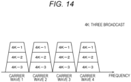
- Fig. 13 is a diagram illustrating an example of a system, which is another form of Fig. 11 , for performing frequency multiplex transmission by using four carrier waves.
- Variable length TLV packet data (4K signal) is supplied to a division multiplexing circuit 42 of a cable television station 41, and the variable length TLV packet data is converted into a fixed length TS packet (divided TLV).
- Outputs of the division multiplexing circuit 42 are supplied to 64-QAM modulation circuits 43a, 43b, 43c, and 43d and frequency-division multiplexed by a combination of 64-QAM modulation systems of the ISDB-C broadcasting system. Then, the outputs are transmitted to a receiver 51 through a cable television transmission path 44.
- a plurality of tuners 52a, 52b, 52c, and 52d selects an RF signal that is each carrier wave on which frequency division has been performed as illustrated in Fig. 14 and converts the frequency of the RF signal into an IF signal.
- Outputs of the tuners 52a to 52d are respectively supplied to 64-QAM demodulation circuits 55a, 55b, 55c, and 55d.
- Demodulation outputs of the demodulation circuits 55a to 55d are supplied to a synthesis circuit 56.
- Fig. 14 illustrates a case where three times of broadcast of 4K broadcasting are frequency-multiplexed.
- the carrier waves of the 64-QAM modulation system of the ISDB-C broadcasting system is demodulated by the 64-QAM demodulation circuits 55a, 55b, 55c, and 55d of the demodulation processing unit 53, and the synthesis circuit 56 synthesizes the demodulated signals.
- a division-multiplexed 4K signal is extracted and supplied to the processing unit 51 that executes demux processing by a demultiplexing unit 57 and decoding processing by a decoder 58 at the subsequent stage.
- Fig. 15 is a schematic diagram of a system in which the present technology is applied to a receiver that receives four multiple carrier waves by using the frequency multiplex transmission system as illustrated in Fig. 14 .
- the receiver four tuners 61a, 61b, 61c, and 61d select RFs that are frequency-divided carrier waves and supply the RFs to a demodulation group 62.
- the demodulation group 62 includes a demodulation circuit 63 including a demodulation processing unit 64d, a demodulation processing unit 64a, a demodulation processing unit 64b, and a demodulation processing unit 64c.
- the demodulation circuit 63 further includes a multi-carrier wave synthesis circuit and an output interface (I/F) 65.
- the demodulation group 62 demodulates the carrier waves of the modulation system of the ISDB-C broadcasting system, synthesizes the demodulated signals, extracts a signal that is a division-multiplexed signal, and transmits the signal to a processing unit 66 that executes demux processing and decoding processing at the subsequent stage.
- the processing unit 66 includes a demultiplexing unit 67 and a decoder 68.
- An IF signal output from the tuner 61d is input to an A/D converter (ADC) of the demodulation processing unit 64d of the demodulation circuit 63, and is input to the multi-carrier wave synthesis circuit 65 after being demodulated. Furthermore, a plurality of TS signals TS1, TS2, and TS3 before multi-carrier wave synthesis respectively output from the demodulation processing units 64a, 64b, and 64c is input to the multi-carrier wave synthesis circuit and the output I/F 65 of the demodulation circuit 63.
- a fixed length packet (TS), a variable length packet (TLV), or a single TS is output from the multi-carrier wave synthesis circuit and the output I/F 65.
- An output interface of the multi-carrier wave synthesis circuit and the output I/F 65 includes a SYNC, a VALID, a CLK, and two-bit DATA terminals. This is an example where an even-numbered bit and an odd-numbered bit are allocated to the outputs of data in a case of the two-bit parallel transmission. In a case where up to eight bits can be output in parallel by the DATA terminal and eight terminals are prepared, all the terminals can be used for inputs from the demodulation processing units 64a, 64b, and 64c and two-bit parallel output. Furthermore, an output interface format may be one-bit serial output instead of the two-bit parallel output. Furthermore, the allocation of the outputs of DATA in a case of the two-bit parallel transmission is not limited to the even-numbered bit and the odd-numbered bit.
- the present technology can have the following configuration.
Landscapes
- Engineering & Computer Science (AREA)
- Signal Processing (AREA)
- Multimedia (AREA)
- Computer Networks & Wireless Communication (AREA)
- Power Engineering (AREA)
- Databases & Information Systems (AREA)
- Quality & Reliability (AREA)
- Two-Way Televisions, Distribution Of Moving Picture Or The Like (AREA)
- Synchronisation In Digital Transmission Systems (AREA)
Applications Claiming Priority (3)
| Application Number | Priority Date | Filing Date | Title |
|---|---|---|---|
| JP2018006380 | 2018-01-18 | ||
| EP18900634.9A EP3742660A4 (de) | 2018-01-18 | 2018-10-15 | Signalverarbeitungsvorrichtung und signalverarbeitungsverfahren |
| PCT/JP2018/038289 WO2019142416A1 (ja) | 2018-01-18 | 2018-10-15 | 信号処理装置および信号処理方法 |
Related Parent Applications (1)
| Application Number | Title | Priority Date | Filing Date |
|---|---|---|---|
| EP18900634.9A Division EP3742660A4 (de) | 2018-01-18 | 2018-10-15 | Signalverarbeitungsvorrichtung und signalverarbeitungsverfahren |
Publications (1)
| Publication Number | Publication Date |
|---|---|
| EP4373103A1 true EP4373103A1 (de) | 2024-05-22 |
Family
ID=67302093
Family Applications (2)
| Application Number | Title | Priority Date | Filing Date |
|---|---|---|---|
| EP18900634.9A Ceased EP3742660A4 (de) | 2018-01-18 | 2018-10-15 | Signalverarbeitungsvorrichtung und signalverarbeitungsverfahren |
| EP24153750.5A Withdrawn EP4373103A1 (de) | 2018-01-18 | 2018-10-15 | Signalverarbeitungsvorrichtung und signalverarbeitungsverfahren |
Family Applications Before (1)
| Application Number | Title | Priority Date | Filing Date |
|---|---|---|---|
| EP18900634.9A Ceased EP3742660A4 (de) | 2018-01-18 | 2018-10-15 | Signalverarbeitungsvorrichtung und signalverarbeitungsverfahren |
Country Status (6)
| Country | Link |
|---|---|
| US (1) | US11477518B2 (de) |
| EP (2) | EP3742660A4 (de) |
| JP (1) | JP7140352B2 (de) |
| KR (1) | KR102540723B1 (de) |
| CN (1) | CN111566986B (de) |
| WO (1) | WO2019142416A1 (de) |
Families Citing this family (1)
| Publication number | Priority date | Publication date | Assignee | Title |
|---|---|---|---|---|
| CN112331135B (zh) * | 2020-11-05 | 2021-09-24 | Tcl华星光电技术有限公司 | 显示面板及驱动方法 |
Citations (5)
| Publication number | Priority date | Publication date | Assignee | Title |
|---|---|---|---|---|
| US20030095057A1 (en) * | 2001-11-21 | 2003-05-22 | Interdigital Technology Corporation | Hybrid parallel/serial bus interface |
| JP2012209675A (ja) | 2011-03-29 | 2012-10-25 | Nippon Hoso Kyokai <Nhk> | 送信装置及び受信装置 |
| JP5145261B2 (ja) | 2009-01-28 | 2013-02-13 | 日本放送協会 | デジタルデータ送信装置及びデジタルデータ受信装置 |
| WO2016199603A1 (ja) * | 2015-06-11 | 2016-12-15 | ソニー株式会社 | 信号処理装置および信号処理方法、並びにプログラム |
| US20170310530A1 (en) * | 2015-01-22 | 2017-10-26 | Socionext Inc. | Divided data transmitting and receiving system |
Family Cites Families (15)
| Publication number | Priority date | Publication date | Assignee | Title |
|---|---|---|---|---|
| JPS5145261B2 (de) | 1972-06-21 | 1976-12-02 | ||
| JPS5444439Y2 (de) | 1974-10-01 | 1979-12-20 | ||
| US6958827B1 (en) * | 1999-10-06 | 2005-10-25 | Canon Kabushiki Kaisha | Image reading apparatus and method and storage medium |
| SG139529A1 (en) * | 2004-01-19 | 2008-02-29 | Nadarajah Sriskanthan | Interface device |
| JP4882269B2 (ja) * | 2005-04-22 | 2012-02-22 | ソニー株式会社 | 多重化装置および多重化方法、プログラム、並びに記録媒体 |
| KR101531910B1 (ko) * | 2007-07-02 | 2015-06-29 | 엘지전자 주식회사 | 방송 수신기 및 방송신호 처리방법 |
| JP2009049600A (ja) * | 2007-08-16 | 2009-03-05 | Ricoh Co Ltd | 差動信号出力装置 |
| US20100110305A1 (en) * | 2008-11-06 | 2010-05-06 | Softasic, Inc. | Method and Apparatus for Processing Multiple Broadcasting Signal Standards in a Broadcasting Signal Receiver System |
| US8499325B2 (en) * | 2009-10-27 | 2013-07-30 | Broadcom Corporation | Method and system for multiplexed transport interface between demodulators (DEMODS) and set-top box (STB) system-on-chips (SoCs) |
| JP5973746B2 (ja) | 2012-02-24 | 2016-08-23 | 日本放送協会 | 送信装置及び受信装置 |
| JP6032945B2 (ja) * | 2012-05-28 | 2016-11-30 | サターン ライセンシング エルエルシーSaturn Licensing LLC | 信号処理装置、及び、信号処理方法 |
| CN110071785B (zh) * | 2014-06-24 | 2021-10-26 | 株式会社索思未来 | 接口方法 |
| JP6497069B2 (ja) * | 2014-12-25 | 2019-04-10 | 富士通株式会社 | 判定帰還型等化回路 |
| JP6290127B2 (ja) * | 2015-03-17 | 2018-03-07 | 株式会社東芝 | 送信システム、伝送スロット化装置、受信装置及び伝送スロット作成方法 |
| WO2016199604A1 (ja) | 2015-06-11 | 2016-12-15 | ソニー株式会社 | 信号処理装置および信号処理方法、並びにプログラム |
-
2018
- 2018-10-15 US US16/960,437 patent/US11477518B2/en active Active
- 2018-10-15 EP EP18900634.9A patent/EP3742660A4/de not_active Ceased
- 2018-10-15 WO PCT/JP2018/038289 patent/WO2019142416A1/ja not_active Ceased
- 2018-10-15 EP EP24153750.5A patent/EP4373103A1/de not_active Withdrawn
- 2018-10-15 JP JP2019565711A patent/JP7140352B2/ja active Active
- 2018-10-15 CN CN201880086104.5A patent/CN111566986B/zh active Active
- 2018-10-15 KR KR1020207018179A patent/KR102540723B1/ko active Active
Patent Citations (6)
| Publication number | Priority date | Publication date | Assignee | Title |
|---|---|---|---|---|
| US20030095057A1 (en) * | 2001-11-21 | 2003-05-22 | Interdigital Technology Corporation | Hybrid parallel/serial bus interface |
| JP5145261B2 (ja) | 2009-01-28 | 2013-02-13 | 日本放送協会 | デジタルデータ送信装置及びデジタルデータ受信装置 |
| JP2012209675A (ja) | 2011-03-29 | 2012-10-25 | Nippon Hoso Kyokai <Nhk> | 送信装置及び受信装置 |
| US20170310530A1 (en) * | 2015-01-22 | 2017-10-26 | Socionext Inc. | Divided data transmitting and receiving system |
| WO2016199603A1 (ja) * | 2015-06-11 | 2016-12-15 | ソニー株式会社 | 信号処理装置および信号処理方法、並びにプログラム |
| US20180139033A1 (en) * | 2015-06-11 | 2018-05-17 | Sony Corporation | Signal processing device, signal processing method, and program |
Non-Patent Citations (4)
| Title |
|---|
| "8K Super Hi-Vision Transmission Technology", NHK SCIENCE & TECHNOLOGY RESEARCH LABORATORIES R&D, no. 152, August 2015 (2015-08-01) |
| "8K UHDTV Cable TV Distribution System with a Channel Bonding Technology", NHK SCIENCE & TECHNOLOGY RESEARCH LABORATORIES R&D, no. 157, May 2016 (2016-05-01) |
| ANONYMOUS: "Low-voltage differential signaling - Wikipedia", 25 November 2017 (2017-11-25), XP093097230, Retrieved from the Internet <URL:https://en.wikipedia.org/w/index.php?title=Low-voltage_differential_signaling&oldid=812063956> [retrieved on 20231101] * |
| ITU-R: "Recommendation ITU-R BO.2098-0 -Transmission system for UHDTV satellite broadcasting", 1 January 2017 (2017-01-01), Geneva, XP055377017, Retrieved from the Internet <URL:https://www.itu.int/dms_pubrec/itu-r/rec/bo/R-REC-BO.2098-0-201612-I!!PDF-E.pdf> [retrieved on 20170530] * |
Also Published As
| Publication number | Publication date |
|---|---|
| CN111566986A (zh) | 2020-08-21 |
| KR20200110312A (ko) | 2020-09-23 |
| US20200351546A1 (en) | 2020-11-05 |
| EP3742660A1 (de) | 2020-11-25 |
| US11477518B2 (en) | 2022-10-18 |
| EP3742660A4 (de) | 2021-03-10 |
| WO2019142416A1 (ja) | 2019-07-25 |
| JP7140352B2 (ja) | 2022-09-21 |
| CN111566986B (zh) | 2023-10-20 |
| JPWO2019142416A1 (ja) | 2021-01-28 |
| KR102540723B1 (ko) | 2023-06-05 |
Similar Documents
| Publication | Publication Date | Title |
|---|---|---|
| CN1312929C (zh) | 地面数字电视广播的单频网系统及其实现方法 | |
| US8345681B2 (en) | Method and system for wireless communication of audio in wireless networks | |
| CN101998159B (zh) | 接收装置和方法及接收系统 | |
| CN102118341B (zh) | 接收设备和方法、程序和接收系统 | |
| JP4848313B2 (ja) | 信号多重装置 | |
| JPH07177475A (ja) | デジタル送信における干渉を最小化するためのランダム化トレーニングシーケンス用送信機を用いた送信システム | |
| JP2021016181A (ja) | 送信方法および送信装置 | |
| KR20000039194A (ko) | 비대칭형 멀티미디어 위성통신 시스템에서 망 동기장치 및 그방법 | |
| US20100329228A1 (en) | Digital broadcast retransmission system, digital broadcast retransmission method, packet converting apparatus, and frequency converting apparatus | |
| KR20010055543A (ko) | 고화질 텔레비전의 티시엠을 이용한 브이에스비 송/수신장치 | |
| US11477518B2 (en) | Signal processing device and signal processing method | |
| CN102118342B (zh) | 接收设备和方法、程序和接收系统 | |
| US9173195B2 (en) | Method and apparatus for transmitting/receiving control information in broadcast communication system | |
| Uehara | Application of MPEG-2 systems to terrestrial ISDB (ISDB-T) | |
| WO2020026558A1 (ja) | 受信装置、通信システム、および、受信装置の制御方法 | |
| US7555066B2 (en) | E8-VSB reception system | |
| Hakamada et al. | An UHDTV cable television distribution in combinations of multiple 64 and 256 QAM channels | |
| US10116895B2 (en) | Signal display output method, apparatus, and system | |
| KR100525848B1 (ko) | 아날로그 방송을 위한 연주소-송신소 링크(stl)를이용한 디지털 tv 송신기의 단일 주파수 네트워크 시스템 | |
| JP2000236308A (ja) | Dvb−spi付加情報伝送方法及び伝送システム | |
| JP4691953B2 (ja) | ディジタル信号送受信システム、並びにそれに用いるディジタル信号送信装置及びディジタル信号受信装置 | |
| KR20060004453A (ko) | 디지털 방송 전송 방식 변환 시스템 및 방법 | |
| CN101207727A (zh) | 用于解调器及解码器的接口装置及数字电视接收系统 | |
| JP2004088324A (ja) | 送信装置及び受信装置並びに周波数多重伝送システム | |
| US20170150188A1 (en) | Broadcast receiving system including broadcast receiving apparatus and controlling method thereof |
Legal Events
| Date | Code | Title | Description |
|---|---|---|---|
| PUAI | Public reference made under article 153(3) epc to a published international application that has entered the european phase |
Free format text: ORIGINAL CODE: 0009012 |
|
| STAA | Information on the status of an ep patent application or granted ep patent |
Free format text: STATUS: THE APPLICATION HAS BEEN PUBLISHED |
|
| AC | Divisional application: reference to earlier application |
Ref document number: 3742660 Country of ref document: EP Kind code of ref document: P |
|
| AK | Designated contracting states |
Kind code of ref document: A1 Designated state(s): AL AT BE BG CH CY CZ DE DK EE ES FI FR GB GR HR HU IE IS IT LI LT LU LV MC MK MT NL NO PL PT RO RS SE SI SK SM TR |
|
| STAA | Information on the status of an ep patent application or granted ep patent |
Free format text: STATUS: REQUEST FOR EXAMINATION WAS MADE |
|
| 17P | Request for examination filed |
Effective date: 20241113 |
|
| RBV | Designated contracting states (corrected) |
Designated state(s): AL AT BE BG CH CY CZ DE DK EE ES FI FR GB GR HR HU IE IS IT LI LT LU LV MC MK MT NL NO PL PT RO RS SE SI SK SM TR |
|
| STAA | Information on the status of an ep patent application or granted ep patent |
Free format text: STATUS: THE APPLICATION HAS BEEN WITHDRAWN |
|
| 18W | Application withdrawn |
Effective date: 20250416 |