EP4373777B1 - Handlauf für eine fahrtreppe oder einen fahrsteig - Google Patents
Handlauf für eine fahrtreppe oder einen fahrsteig Download PDFInfo
- Publication number
- EP4373777B1 EP4373777B1 EP22735481.8A EP22735481A EP4373777B1 EP 4373777 B1 EP4373777 B1 EP 4373777B1 EP 22735481 A EP22735481 A EP 22735481A EP 4373777 B1 EP4373777 B1 EP 4373777B1
- Authority
- EP
- European Patent Office
- Prior art keywords
- handrail
- sheet
- sheet metal
- metal strip
- beads
- Prior art date
- Legal status (The legal status is an assumption and is not a legal conclusion. Google has not performed a legal analysis and makes no representation as to the accuracy of the status listed.)
- Active
Links
Images

Classifications
-
- B—PERFORMING OPERATIONS; TRANSPORTING
- B66—HOISTING; LIFTING; HAULING
- B66B—ELEVATORS; ESCALATORS OR MOVING WALKWAYS
- B66B23/00—Component parts of escalators or moving walkways
- B66B23/22—Balustrades
- B66B23/24—Handrails
Definitions
- the present invention relates to a handrail for a passenger transport system configured as an escalator or moving walkway. Furthermore, the invention relates to a passenger transport system equipped with such a handrail.
- a handrail or handrail belt for an escalator or moving walkway typically comprises several fabric layers, each of which can be rubberized on one or both sides. Tensile members in the form of steel strands, which can also be rubberized, can be incorporated into the fabric layers. The fabric layers can be covered by an external rubber protective layer.
- Such a handrail is usually manufactured in an endless length specifically adapted to the respective escalator or moving walkway. This can be very complex and, on the other hand, can be associated with certain restrictions during installation and maintenance, not least due to the relatively high weight of the handrail. Furthermore, the so-called splicing of handrail belts—that is, the joining of the two ends of a handrail belt to form an endless handrail belt—is very complex and requires expensive special tools.
- handrails made of plastics and fabric layers are subject to aging processes caused by environmental factors and alternating bending, which can lead to cracks in the surface of the handrail. Germs and spores can nest and multiply in cracked handrail surfaces. Furthermore, the rubber-like handrails are often the target of vandalism, where, for example, gouges are carved into the handrails with knives or entire pieces are cut out.
- EP 1799605 A1 describes, for example, a handrail belt of the aforementioned type made of polyurethane with steel strands.
- US2956662A discloses the preamble of claim 1.
- a first aspect of the invention relates to a handrail for a passenger transport system in the form of an escalator or a moving walkway.
- the handrail comprises a sheet metal strip, which is divided transversely to its longitudinal direction into two edge sections and a central section located between the two edge sections. The edge sections are each bent into a bead. The central section is shaped into a handrail back extending between the beads for resting a hand.
- Sheet metal strip can be understood as an elongated, band- or strip-shaped piece of sheet metal, for example, sheet steel.
- the sheet metal strip can have a thickness or material strength of typically between 0.1 mm and 0.5 mm, for example, 0.2 mm.
- edge section can be understood as an outer edge of the sheet metal strip extending along a longitudinal edge of the sheet metal strip.
- the middle section can be an inner section of the sheet metal strip that connects the two (opposite) edge sections.
- the descriptive division of the sheet metal strip into edge sections and a central section can be understood as two imaginary straight lines drawn parallel to the longitudinal edges of the sheet metal strip, which delimit the central section from the edge sections.
- the edge sections and the central section can be understood as different, adjacent sub-areas of one and the same piece of sheet metal strip.
- the sheet metal strip, with its two edge sections and its central section can be formed as a single component. This means that the handrail can be formed as an entire sheet metal strip or as a section of sheet metal strip by forming a single sheet.
- a “bead” can be understood as an elongated, at least partially rounded thickening on the back of the handrail, which can be at least partially tubular, i.e., hollow inside.
- the beads can be created, for example, by rolling or milling the respective edge section.
- the beads can extend on opposite sides of the handrail back over its entire length or at least over a large part of its length.
- the diameter of the beads can, for example, be selected depending on the desired height of the handrail. The larger the diameter of the beads, the higher the handrail can be. In other words, the beads can serve to optimally adapt the cross-sectional shape of the handrail to a hand grasping the handrail. Furthermore, the beads increase the stability of the handrail.
- the beads can be curved so that they face a balustrade of the escalator or moving walkway during operation of the handrail, i.e., they are arranged on an inner side of the handrail after the handrail has been connected to form a closed ring.
- a surface of the back of the handrail, on which the hand can be placed, can correspond to an outer side of the handrail.
- the sheet metal strip of the handrail can, for example, be connected to form a closed ring and/or assembled from several sheet metal strip parts by the ends of the sheet metal strip or the sheet metal strip parts being connected to one another in a force-fitting and/or form-fitting manner, for example by welding, soldering or gluing, by forming, for example by flanging, folding or clinching, and/or by using additional connecting elements, for example in the form of screws, rivets, clamping rings or clamps.
- the ends of the sheet metal strip or the sheet metal strip parts can be welded together butt-welded, overlapping, with or without filler metal.
- the sheet metal strip or the sheet metal strip parts can have the same thickness in an overlapping area where the ends of the sheet metal strip or the sheet metal strip parts overlap as outside the overlapping area.
- the back of the handrail can be mostly flat. Additionally or alternatively, the back of the handrail can be rounded, for example, curved outwards.
- the handrail can be at least partially lined or filled with a filling material, such as a special foam, for example polyurethane foam.
- a filling material such as a special foam, for example polyurethane foam.
- Such a handrail has the advantage that it can be very easily cut to a specific length and only needs to be connected to form a ring when the handrail is mounted or when the passenger transport system is installed, for example by welding the ends of the appropriately cut sheet metal strip together or by joining them in some other way using a material and/or form fit.
- such a handrail is significantly lighter than conventional rubber and fabric-based handrails. Tests have shown that the weight of the handrail can be reduced to approximately 0.6 kg/m. This not only has a positive impact on assembly and installation, but also, due to the corresponding reduction in friction, has a positive impact on the energy consumption of the passenger transport system equipped with such a handrail.
- the handrail is made largely of metal, it can be manufactured much more cheaply, as vulcanization or other complex processing steps that are usually required in connection with the construction of rubber and fabric-based handrails can be completely eliminated.
- the handrail is very easy to clean, i.e., keep hygienically clean, thanks to its metallic surface.
- the metallic material of the handrail can withstand chemicals used for cleaning or disinfection without, for example, becoming brittle, corroding, or otherwise aging over time.
- the metallic material can also withstand plasma, which may be used for disinfection.
- the metallic material prevents the handrail from becoming brittle and developing cracks in which dirt and germs could nest.
- the surface of the sheet metal strip or the handrail formed from it also has germ-reducing properties.
- such a handrail is also highly vandal-resistant, as its surface can hardly or only very slightly be worked on with a knife.
- the hard surface eliminates any incentive to even attempt to damage it.
- the metal handrail is pleasant to the touch, as this material has a very clean feel and users are familiar with the feel from static stair railings, for example.
- the metal strip makes the handrail easier to recycle, as there is no composite material, as is the case with conventional handrails for escalators and moving walkways.
- a second aspect of the invention relates to a passenger transport system in the form of an escalator or moving walkway, comprising a handrail, as described above and below, and a drive device with at least one drive wheel for driving the handrail.
- the drive wheel and the handrail engage with one another in a form-fitting manner.
- the drive wheel can engage with transverse grooves and/or engagement elements of the handrail, as described below.
- the drive device can comprise an electric motor that drives the drive wheel, for example a spur-toothed plastic wheel.
- the drive device can also comprise several drive wheels that engage with the handrail in a form-fitting manner at several points.
- a friction wheel can also be used as the drive wheel, which transmits the drive force to the handrail via friction forces.
- Also disclosed here is a method for producing a handrail for a passenger transport system in the form of an escalator or a moving walkway.
- the method comprises at least the following steps, which can be carried out in the specified order or in a suitable alternative order: providing a sheet metal strip divided transversely to its longitudinal direction into two edge sections and a central section located between the two edge sections; bending each edge section into a bead, and forming the central section into a handrail back extending between the beads for resting a hand on.
- This process can be a multi-stage process in which the sheet metal strip is bent by rolling using several forming rollers in several successive rolling stations so that it ultimately has the desired handrail shape.
- the sheet metal strip can then be cut to a specific length as required and, for example, only at the installation site, joined at its ends to form a closed ring, for example by butt-welding the ends together. This process can significantly reduce the cost and speed up the production of the handrail.
- the beads On their underside, which faces away from the back of the handrail, the beads each have a plurality of transverse grooves distributed along the length of the sheet metal strip.
- the transverse grooves can, for example, be embossed depressions whose length can run transversely to the length of the sheet metal strip or handrail.
- the transverse grooves can drastically reduce the flexural rigidity of the cross-section, thereby improving the elastic deformability of the sheet metal strip under bending loads, such as those that occur in the deflection areas of the handrail.
- the handrail can also be used in combination with escalators or moving walkways, which require smaller bending radii, without the need for additional adaptations.
- the beads each have a rounded bead section and a straight fastening section perpendicular to their longitudinal direction.
- the rounded bead section can have the transverse grooves, and the straight fastening section can be attached to the handrail back.
- the two straight fastening sections can, for example, be arranged between the two rounded bead sections.
- the rounded bead sections can, for example, each have a teardrop-shaped cross-section.
- the straight fastening sections can, for example, be spot-welded to the handrail back at several points. Other joining methods are also possible. Such beads can be produced with relatively little effort.
- the transverse grooves of at least one of the beads can be configured to positively engage with at least one drive wheel of a drive device for driving the handrail.
- at least one of the beads, including its transverse grooves can function as a type of flexible rack or rail that can mesh with a corresponding drive wheel of the drive device.
- the transverse grooves can each have a V-shaped cross-section.
- One or both flanks of the V-shaped cross-section can be straight or curved, or partly straight and partly curved.
- the two flanks can be connected to each other, for example, via a rounded groove that forms a bottom of the respective transverse groove.
- the V-shaped cross-section can, for example, have an opening angle of 45 degrees. Depending on the application, any other opening angles are also possible.
- Transverse grooves shaped in this way have the advantage of being complementary to various tooth flank geometries of common gears.
- the transverse grooves of different beads can be arranged in pairs opposite each other.
- each of the transverse grooves of one bead can be arranged exactly opposite one of the transverse grooves of the other bead, i.e., the two transverse grooves share a common longitudinal axis. In this way, the elastic deformability of the handrail can be further improved and thus its service life extended.
- the handrail may further comprise a plurality of engagement elements attached to the sheet metal strip, which may be designed to to engage positively with at least one drive wheel of a drive device for driving the handrail.
- the engagement elements can be arranged between the beads in the longitudinal direction of the sheet metal strip.
- the engagement elements can be attached individually to the sheet metal strip, for example welded, screwed or clamped thereto, or each can be attached to the sheet metal strip via an additional support (see below).
- the engagement elements can, for example, be arranged centrally between the two beads in the longitudinal direction of the sheet metal strip.
- the engagement elements can be distributed over the entire length of the sheet metal strip. This enables the mechanical coupling of the handrail to the drive wheel independently of the transverse grooves.
- the engagement elements can be designed to prevent the handrail from deviating horizontally or vertically from its ideal line during operation.
- the engagement elements can be attached to the sheet metal strip via a carrier strip.
- the engagement elements can be welded, soldered, glued, screwed, or clamped to the carrier strip.
- the carrier strip can, for example, be inserted into the sheet metal strip and extend over its entire length or at least a large part of its entire length.
- the carrier strip can be enclosed on both sides by the two beads.
- the carrier strip can be centered on the sheet metal strip by means of the two beads.
- the carrier strip can be connected to the sheet metal strip at several points or continuously in order to transmit drive forces to the sheet metal strip.
- the support strip can be designed as an additional sheet metal strip. This further simplifies the production of the handrail.
- the support strip can be easily attached to the sheet metal strip by welding or soldering, for example.
- the sheet metal strip can be combined with at least one other sheet metal strip to reinforce the sheet metal strip.
- the support strip can be inserted into a gap between the straight fastening sections and the handrail back, whereby the straight fastening sections can each be attached to the handrail back via the support strip.
- the handrail can be designed to be particularly torsionally rigid.
- the straight fastening sections, the support strip, and the handrail back can be spot-welded or roll-welded together at suitable locations, which can, for example, be distributed over the entire length of the sheet metal strip. Other joining methods are also possible.
- the handrail can further comprise a heating device and/or cooling device for heating or cooling the sheet metal strip.
- the heating device can be, for example, a fan or an induction heater for contactless heating of the sheet metal strip.
- the sheet metal strip can be brought to a temperature that is perceived as comfortable.
- a Peltier element can be used, for example, the cold generated by the element being blown onto the handrail as cooling air, for example by a fan.
- a handrail formed from a sheet metal strip offers enormous advantages, as its aging behavior, sliding properties, and mechanical properties are hardly affected by temperature fluctuations.
- the handrail can be heated or cooled very easily due to its low mass and good thermal conductivity.
- the sheet metal strip can be made of stainless steel. This increases the corrosion resistance of the handrail. Additionally or alternatively, the sheet metal strip can be at least partially coated with a plastic or metal layer. This allows the external appearance of the handrail to be adapted to different requirements with little effort. Such a plastic or metal layer also acts as an additional protective layer to protect the sheet metal strip from environmental influences.
- the sheet metal strip can be assembled from at least two sheet metal strip parts.
- each sheet metal strip part can be shorter than the sheet metal strip, or, in other words, the total length of the sheet metal strip can be equal to the sum of the individual lengths of the sheet metal strip parts.
- the sheet metal strip parts can be welded or soldered together to form the sheet metal strip. In this way, the handrail can be installed relatively easily even if it is longer than average. For example, it is possible for the sheet metal strip parts to be transported individually to the installation site and then assembled there.
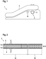
- FIG. 1 shows a passenger transport system 1 configured as an escalator.
- the passenger transport system 1 comprises a handrail 2 and a drive device 4 that drives the handrail 2 by means of a drive wheel 3.
- the drive wheel 3 which can be rotated by means of an electric motor (not shown) of the drive device 4, engages positively with a correspondingly shaped structure on the handrail 2.
- the structure of the handrail 2 is described in more detail below.
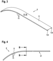
- Figure 2 shows a plan view of the underside of the handrail 2.
- the handrail 2 comprises a sheet metal strip 5, which, viewed transversely to its longitudinal direction 6, comprises two outer edge sections 7 and a central section 8 that directly connects the two edge sections 7.
- the two edge sections 7 and the central section 8 extend parallel to each other and in the longitudinal direction 6 of the handrail 2.
- the sheet metal strip 5 can be made in one piece or can be assembled from at least two sheet metal strip parts 5a, 5b, for example sheet metal strips.
- Each of the two edge sections 7 is bent into a bead 9 with a drop-shaped cross-section (see also Figure 5 ), whereby the middle section 8 forms a handrail back 10 connecting the two beads 9 to each other for resting a hand.
- the handrail back 10 is straight transversely to the longitudinal direction 6 (see also Figure 3 ). Of course, it could also be slightly curved.
- each of the beads 9 has on its bead underside 17 a plurality of transverse grooves 11 distributed in the longitudinal direction 6, here in the form of recesses embossed in the respective bead 9.
- the transverse grooves 11 are arranged, for example, distributed over the entire length of the sheet metal strip 5 or the handrail 2.
- the transverse grooves 11 of different beads 9 are arranged in pairs opposite each other.
- an offset arrangement of the transverse grooves 11 of one bead 9 relative to the transverse grooves 11 of the other bead 9 is also possible.
- the transverse grooves 11 can each have a V-shaped cross-section.
- the beads 9 each comprise a round, here drop-shaped, bent bead section 12 and a straight fastening section 13, wherein the two straight fastening sections 13 are arranged between the two round bent bead sections 12 and are each fastened to the handrail back 10, for example welded thereto.
- a carrier strip 14 for example in the form of an additional sheet metal strip, is additionally inserted into a gap between the handrail back 10 and the two straight fastening sections 13 and fastened to the sheet metal strip 5.
- engagement elements 15 are attached to the carrier strip 14 centrally between the two beads 9, into which the drive wheel 3 can positively engage.
- the engagement elements 15 can be distributed over the entire length of the sheet metal strip 5.
- the handrail 2 can be heated and/or cooled by means of an optional heating device and/or cooling device 16 (see Figure 1 ) to a temperature that is perceived as comfortable.
Landscapes
- Escalators And Moving Walkways (AREA)
Description
- Die vorliegende Erfindung betrifft einen Handlauf für eine Personentransportanlage, welche als Fahrtreppe oder Fahrsteig ausgestaltet ist. Des Weiteren betrifft die Erfindung eine Personentransportanlage, die mit einem solchen Handlauf ausgestattet ist.
- Ein Handlauf beziehungsweise Handlaufriemen für eine Fahrtreppe oder einen Fahrsteig umfasst in der Regel mehrere Gewebeschichten, die jeweils ein- oder beidseitig gummiert sein können. In die Gewebeschichten kann ein Zugträger in Form von Stahllitzen eingearbeitet sein, die ebenfalls gummiert sein können. Die Gewebeschichten können von einer aussen liegenden Gummischutzschicht ummantelt sein. Ein solcher Handlauf wird in der Regel endlos mit einer speziell an die jeweilige Fahrtreppe oder den jeweiligen Fahrsteig angepassten Länge hergestellt, was zum einen sehr aufwendig und zum anderen mit gewissen Einschränkungen bei der Montage oder Wartung verbunden sein kann, nicht zuletzt aufgrund des relativ hohen Gewichts des Handlaufs. Zudem ist das sogenannte Spleissen von Handlaufriemen, also das Verbinden der beiden Enden eines Handlaufriemens zu einem endlosen Handlaufriemen sehr aufwändig und erfordert teure Spezialwerkzeuge. Des Weiteren unterstehen die aus Kunststoffen und Gewebeschichten gefertigten Handläufe umweltbedingten und durch Biegewechsel verursachten Alterungsprozessen, welche zu Rissbildungen in der Oberfläche des Handlaufs führen können. In rissigen Handlaufoberflächen können sich Keime und Sporen einnisten und vermehren. Zudem sind die gummiartigen Handläufe oftmals Ziel von Vandalenakten, bei denen beispielsweise mittels Messern Furchen eingeritzt oder ganze Stücke aus den Handläufen herausgeschnitten werden.
EP 1799605 A1 beschreibt zum Beispiel einen Handlaufriemen der vorgenannten Art aus Polyurethan mit Stahllitzen.US2956662A offenbart den Oberbegriff des Anspruchs 1. - Es kann daher ein Bedarf an einem Handlauf bestehen, der vandalensicher ist, einfacher montiert und/oder billiger hergestellt werden kann. Ferner kann ein Bedarf an einer entsprechenden Personentransportanlage und an einem entsprechenden Herstellungsverfahren bestehen.
- Einem solchen Bedarf kann durch den Gegenstand der unabhängigen Ansprüche entsprochen werden. Vorteilhafte Ausführungsformen sind in den abhängigen Ansprüchen und in der nachstehenden Beschreibung definiert.
- Ein erster Aspekt der Erfindung betrifft einen Handlauf für eine Personentransportanlage in Form einer Fahrtreppe oder eines Fahrsteigs. Der Handlauf umfasst ein Blechband, das quer zu seiner Längsrichtung in zwei Randabschnitte und einen zwischen den zwei Randabschnitten liegenden mittleren Abschnitt unterteilt ist. Die Randabschnitte sind jeweils zu einem Wulst gebogen. Der mittlere Abschnitt ist zu einem sich zwischen den Wülsten erstreckenden Handlaufrücken zum Auflegen einer Hand geformt.
- Unter "Blechband" kann ein längliches, band- oder streifenförmiges Stück Metallblech, beispielsweise Stahlblech, verstanden werden. Das Blechband kann eine Dicke beziehungsweise Materialstärke von typischerweise zwischen 0,1 mm und 0,5 mm, beispielsweise 0,2 mm, aufweisen.
- Unter "Randabschnitt" kann ein sich entlang einer Längskante des Blechbands erstreckender Aussenrand des Blechbands verstanden werden.
- Beim mittleren Abschnitt kann es sich um einen die beiden (einander gegenüberliegenden) Randabschnitte miteinander verbindenden, innen liegenden Abschnitt des Blechbands handeln.
- Die bezeichnungsmässige Unterteilung des Blechbands in die Randabschnitte und den mittleren Abschnitt kann so verstanden werden, dass parallel zu den Längskanten des Blechbands zwei gedachte gerade Linien gezogen werden, die den mittleren Abschnitt zu den Randabschnitten hin begrenzen. Anders ausgedrückt können die Randabschnitte und der mittlere Abschnitt als verschiedene aneinandergrenzende Teilbereiche ein und desselben Stücks Blechband aufgefasst werden. Das Blechband kann hierbei mit seinen beiden Randabschnitten und seinem mittleren Abschnitt als einstückiges Bauelement ausgebildet sein. Das heisst, der Handlauf kann als gesamtes Blechband oder Blechbandabschnitt durch Umformen eines einzelnen Bleches ausgebildet werden.
- Unter "Wulst" kann eine längliche, zumindest teilweise gerundete Verdickung am Handlaufrücken verstanden werden, die zumindest teilweise rohrförmig, also innen hohl, sein kann. Die Wülste können beispielsweise durch entsprechendes Rollen oder Walzen des jeweiligen Randabschnitts erzeugt worden sein. Die Wülste können sich an einander gegenüberliegenden Seiten des Handlaufrückens jeweils über dessen gesamte Länge oder zumindest über einen Grossteil dessen Länge erstrecken.
- Ein jeweiliger Durchmesser der Wülste kann beispielsweise in Abhängigkeit von einer gewünschten Höhe des Handlaufs gewählt worden sein. Dabei kann der Handlauf umso höher ausfallen, je grösser der jeweilige Durchmesser der Wülste ist. Anders ausgedrückt können die Wülste dazu dienen, die Querschnittsform des Handlaufs optimal an eine den Handlauf umgreifende Hand anzupassen. Zudem wird mittels der Wülste die Stabilität des Handlaufs erhöht.
- Die Wülste können so gebogen sein, dass sie im Betrieb des Handlaufs einer Balustrade der Fahrtreppe oder des Fahrsteigs zugewandt sind, d. h. an einer Innenseite des Handlaufs angeordnet sind, nachdem der Handlauf zu einem geschlossenen Ring verbunden worden ist. Dabei kann eine Oberfläche des Handlaufrückens, auf den die Hand aufgelegt werden kann, einer Aussenseite des Handlaufs entsprechen.
- Das Blechband des Handlaufs kann beispielsweise zu einem geschlossenen Ring verbunden und/oder aus mehreren Blechbandteilen zusammengefügt werden, indem die Enden des Blechbands beziehungsweise der Blechbandteile stoffschlüssig, beispielsweise durch Schweissen, Löten oder Kleben, durch Umformen, beispielsweise durch Bördeln, Falzen oder Clinchen, und/oder unter Verwendung zusätzlicher Verbindungselemente, beispielsweise in Form von Schrauben, Nieten, Spannringen oder Klammern, kraft- und/oder formschlüssig miteinander verbunden werden.
- Beispielsweise können die Enden des Blechbands beziehungsweise der Blechbandteile stumpf, überlappend, mit oder ohne Zusatzwerkstoff miteinander verschweisst werden. Insbesondere kann das Blechband beziehungsweise können die Blechbandteile in einem Überlappungsbereich, in dem sich die Enden des Blechbands beziehungsweise der Blechbandteile überlappen, die gleiche Dicke wie ausserhalb des Überlappungsbereichs aufweisen.
- Der Handlaufrücken kann beispielsweise grösstenteils flach sein. Zusätzlich oder alternativ kann der Handlaufrücken gerundet, beispielsweise nach aussen gewölbt sein.
- Zusätzlich kann der Handlauf zumindest teilweise mit einem Füllmaterial, etwa einem speziellen Schaum, zum Beispiel Polyurethanschaum, unterfüttert oder ausgefüllt sein.
- Ein solcher Handlauf hat den Vorteil, dass er sehr einfach auf eine bestimmte Länge gebracht werden kann und erst bei der Montage des Handlaufs oder bei der Installation der Personentransportanlage zu einem Ring verbunden zu werden braucht, etwa indem die Enden des passend abgelängten Blechbands miteinander verschweisst oder in sonstiger Weise stoff- und/oder formschlüssig miteinander verbunden werden.
- Zudem weist ein solcher Handlauf im Vergleich zu üblichen gummi- und gewebebasierten Handläufen ein deutlich geringeres Gewicht auf. Versuche haben gezeigt, dass sich das Gewicht des Handlaufs auf etwa 0,6 kg/m verringern lässt. Dies wirkt sich nicht nur positiv auf die Montage beziehungsweise Installation, sondern aufgrund der entsprechend verringerten Reibung auch positiv auf den Energieverbrauch der Personentransportanlage aus, die mit einem solchen Handlauf ausgestattet ist.
- Dadurch, dass der Handlauf grösstenteils aus Metall besteht, kann der Handlauf deutlich billiger hergestellt werden, da Vulkanisierungs- oder sonstige aufwendige Bearbeitungsschritte, die üblicherweise im Zusammenhang mit dem Aufbau gummi- und gewebebasierter Handläufe erforderlich sind, vollständig entfallen können.
- Zudem lässt sich der Handlauf aufgrund seiner metallischen Oberfläche sehr leicht reinigen, d. h. hygienisch sauber halten. Insbesondere kann das metallische Material des Handlaufs Chemikalien, wie sie zum Reinigen oder Desinfizieren eingesetzt werden können, widerstehen, ohne zum Beispiel mit der Zeit zu verspröden, zu korrodieren oder in anderer Weise zu altern. Auch einem eventuell zum Desinfizieren eingesetzten Plasma kann das metallische Material gut widerstehen. Im Gegensatz zu Kunststoffriemen kann der Handlauf dank seines metallischen Materials nicht verspröden und Risse bilden, in denen sich Schmutz und Keime einnisten könnten. Je nach verwendeter Metalllegierung weist die Oberfläche des Blechbandes beziehungsweise des daraus geformten Handlaufes zudem keimreduzierende Eigenschaften auf. Des Weiteren ist ein solcher Handlauf auch sehr Vandalensicher, da dessen Oberfläche kaum oder nur sehr geringfügig mit einem Messer bearbeitet werden kann. Außerdem fehlt wegen der harten Oberfläche auch der Anreiz, eine Beschädigung überhaupt zu versuchen.
- Ausserdem ist der metallische Handlauf angenehm zu greifen, da dieses Material sich sehr sauber anfühlt und den Benutzern die Haptik beispielsweise von statischen Treppengeländern her bekannt ist. Zudem wird das Recycling des Handlaufs dank des Blechbands vereinfacht, da kein Materialverbund vorliegt, wie bei einem herkömmlichen Handlauf für Fahrtreppen und Fahrsteige.
- Ein zweiter Aspekt der Erfindung betrifft eine Personentransportanlage in Form einer Fahrtreppe oder eines Fahrsteigs, die einen Handlauf, wie er vor- und nachstehend beschrieben wird, und eine Antriebseinrichtung mit mindestens einem Antriebsrad zum Antreiben des Handlaufs umfasst. Dabei sind das Antriebsrad und der Handlauf formschlüssig ineinander eingreifen. Beispielsweise kann das Antriebsrad formschlüssig in Querrillen und/oder Eingriffselemente des Handlaufs, wie sie nachstehend beschrieben werden, eingreifen. Die Antriebseinrichtung kann einen Elektromotor umfassen, der das Antriebsrad, beispielsweise ein stirnverzahntes Kunststoffrad, antreibt. Die Antriebseinrichtung kann auch mehrere Antriebsräder umfassen, die an mehreren Stellen formschlüssig in den Handlauf eingreifen. Selbstverständlich kann auch ein Friktionsrad als Antriebsrad verwendet werden, welches die Antriebskraft über Reibungskräfte an den Handlauf überträgt.
- Hier ist auch offenbart ein Verfahren zum Herstellen eines Handlaufs für eine Personentransportanlage in Form einer Fahrtreppe oder eines Fahrsteigs. Das Verfahren umfasst zumindest die folgenden Schritte, die in der angegebenen oder auch in einer geeigneten anderen Reihenfolge ausgeführt werden können: Bereitstellen eines Blechbands, das quer zu seiner Längsrichtung in zwei Randabschnitte und einen zwischen den zwei Randabschnitten liegenden mittleren Abschnitt unterteilt ist; Biegen eines jeden Randabschnitts zu einem Wulst und Formen des mittleren Abschnitts zu einem sich zwischen den Wülsten erstreckenden Handlaufrücken zum Auflegen einer Hand.
- Bei diesem Verfahren kann es sich um ein mehrstufiges Verfahren handeln, in dem das Blechband durch Rollen mittels mehrerer formgebender Walzen in mehreren aufeinanderfolgenden Rollstationen so gebogen wird, dass es am Ende die gewünschte Handlaufform aufweist.
- Anschliessend kann das Blechband je nach Bedarf auf eine bestimmte Länge abgelängt werden und, beispielsweise erst am Montageort, an seinen Enden zu einem geschlossenen Ring verbunden werden, etwa indem die Enden stumpf miteinander verschweisst werden. Mithilfe eines solchen Verfahrens kann die Herstellung des Handlaufs erheblich verbilligt und beschleunigt werden.
- Merkmale des Verfahrens, wie es vor- und nachstehend beschrieben wird, können auch Merkmale des Handlaufs sein und umgekehrt.
- Mögliche Merkmale und Vorteile von Ausführungsformen der Erfindung können unter anderem und ohne die Erfindung einzuschränken als auf den nachstehend beschriebenen Ideen und Erkenntnissen beruhend angesehen werden.
- Die Wülste weisen jeweils an ihrer Wulstunterseite, welche dem Handlaufrücken abgewandt ist, eine Mehrzahl von in Längsrichtung des Blechbands verteilt angeordneten Querrillen auf. Bei den Querrillen kann es sich beispielsweise um eingeprägte Vertiefungen handeln, deren Längsrichtung quer zur Längsrichtung des Blechbands beziehungsweise des Handlaufs verlaufen kann. Mittels der Querrillen kann die Biegesteifigkeit des Querschnitts drastisch reduziert, und damit die elastische Verformbarkeit des Blechbands bei Biegebelastungen, wie sie in Umlenkbereichen des Handlaufs auftreten, verbessert werden. Somit kann der Handlauf auch in Kombination mit Fahrtreppen oder Fahrsteigen, die kleinere Biegeradien vorgeben, ohne zusätzliche Anpassungen eingesetzt werden.
- Die Wülste weisen jeweils quer zu ihrer Längsrichtung einen rund gebogenen Wulstabschnitt und einen geraden Befestigungsabschnitt auf. Dabei kann der rund gebogene Wulstabschnitt die Querrillen aufweisen und der gerade Befestigungsabschnitt kann am Handlaufrücken befestigt sein. Die beiden geraden Befestigungsabschnitte können beispielsweise zwischen den beiden rund gebogenen Wulstabschnitten angeordnet sein. Die rund gebogenen Wulstabschnitte können beispielsweise jeweils einen tropfenförmigen Querschnitt aufweisen. Die geraden Befestigungsabschnitte können beispielsweise an mehreren Stellen mit dem Handlaufrücken punktverschweisst sein. Möglich sind aber auch andere Fügemethoden. Derartige Wülste können mit verhältnismässig geringem Aufwand erzeugt werden.
- Gemäss einer Ausführungsform können die Querrillen mindestens eines der Wülste ausgebildet sein, um formschlüssig in mindestens ein Antriebsrad einer Antriebseinrichtung zum Antreiben des Handlaufs einzugreifen. Anders ausgedrückt kann mindestens einer der Wülste einschliesslich seiner Querrillen als eine Art biegbare Zahnstange oder -schiene fungieren, die mit einem entsprechenden Antriebsrad der Antriebseinrichtung kämmen kann. Somit sind keine zusätzlichen Bauteile erforderlich, um das fertig geformte Blechband beziehungsweise den Handlauf mit dem Antriebsrad mechanisch zu koppeln.
- Gemäss einer Ausführungsform können die Querrillen jeweils einen v-förmigen Querschnitt aufweisen. Eine oder beide Flanken des v-förmigen Querschnitts können geradlinig oder gekrümmt oder teils geradlinig, teils gekrümmt verlaufen. Die beiden Flanken können beispielsweise über eine verrundete Nut, die einen Boden der jeweiligen Querrille bildet, miteinander verbunden sein. Der v-förmige Querschnitt kann beispielsweise einen Öffnungswinkel von 45 Grad aufweisen. Je nach Anwendung sind aber auch beliebige andere Öffnungswinkel möglich. Derart geformte Querrillen haben den Vorteil, dass sie mit verschiedenen Zahnflankengeometrien gängiger Zahnräder komplementär sind.
- Gemäss einer Ausführungsform können die Querrillen verschiedener Wülste paarweise einander gegenüberliegend angeordnet sein. Anders ausgedrückt kann jeder der Querrillen des einen Wulstes genau eine der Querrillen des anderen Wulstes gegenüberliegend angeordnet sein, d. h., die beiden Querrillen haben eine gemeinsame Längsachse. Auf diese Weise kann die elastische Verformbarkeit des Handlaufs weiter verbessert und damit dessen Lebensdauer verlängert werden.
- Gemäss einer Ausführungsform kann der Handlauf ferner eine Mehrzahl von am Blechband befestigten Eingriffselementen umfassen, die ausgebildet sein können, um formschlüssig in mindestens ein Antriebsrad einer Antriebseinrichtung zum Antreiben des Handlaufs einzugreifen. Dabei können die Eingriffselemente zwischen den Wülsten in Längsrichtung des Blechbands verteilt angeordnet sein. Die Eingriffselemente können einzeln am Blechband befestigt sein, beispielsweise damit verschweisst, verschraubt oder verklemmt sein, oder jeweils über einen zusätzlichen Träger am Blechband befestigt sein (siehe unten). Die Eingriffselemente können beispielsweise mittig zwischen den zwei Wülsten in Längsrichtung des Blechbands verteilt angeordnet sein. Dabei können die Eingriffselemente über die gesamte Länge des Blechbands verteilt sein. Dies ermöglicht die mechanische Kopplung des Handlaufs mit dem Antriebsrad unabhängig von den Querrillen. Zudem können die Eingriffselemente ausgeführt sein, um zu verhindern, dass der Handlauf im Betrieb horizontal oder vertikal von seiner Ideallinie abweicht.
- Gemäss einer Ausführungsform können die Eingriffselemente über ein Trägerband am Blechband befestigt sein. Beispielsweise können die Eingriffselemente mit dem Trägerband verschweisst, verlötet, verklebt, verschraubt oder verklemmt sein. Das Trägerband kann beispielsweise in das Blechband eingeschoben sein und sich über dessen gesamte Länge oder zumindest einen Grossteil dessen gesamter Länge erstrecken. Beispielsweise ist es möglich, dass das Trägerband beidseitig von den beiden Wülsten eingefasst ist. Anders ausgedrückt kann das Trägerband mittels der beiden Wülste am Blechband zentriert sein. Das Trägerband kann an mehreren Stellen oder durchgängig mit dem Blechband verbunden sein, um Antriebskräfte auf das Blechband zu übertragen.
- Gemäss einer Ausführungsform kann das Trägerband als ein zusätzliches Blechband ausgeführt sein. Damit kann die Herstellung des Handlaufs weiter vereinfacht werden. Beispielsweise kann das Trägerband in diesem Fall sehr einfach durch Schweissen oder Löten am Blechband befestigt werden.
- Unabhängig davon kann das Blechband mit mindestens einem weiteren Blechband kombiniert sein, um das Blechband zu verstärken.
- Gemäss einer Ausführungsform kann das Trägerband in einen Spalt zwischen den geraden Befestigungsabschnitten und dem Handlaufrücken eingefügt sein, wobei die geraden Befestigungsabschnitte jeweils über das Trägerband am Handlaufrücken befestigt sein können. Auf diese Weise kann der Handlauf besonders verwindungssteif ausgeführt werden. Beispielsweise können die geraden Befestigungsabschnitte, das Trägerband und der Handlaufrücken an geeigneten Stellen, die beispielsweise über die gesamte Länge des Blechbands verteilt sein können, miteinander punktverschweisst oder rollgeschweisst sein. Möglich sind aber auch andere Fügemethoden.
- Gemäss einer Ausführungsform kann der Handlauf ferner eine Heizeinrichtung und/oder Kühleinrichtung zum Beheizen beziehungsweise Kühlen des Blechbands umfassen. Bei der Heizeinrichtung kann es sich beispielsweise um ein Gebläse oder eine Induktionsheizung zur berührungslosen Erwärmung des Blechbands handeln. Auf diese Weise kann das Blechband auf eine als angenehm empfundene Temperatur gebracht werden. Zur Kühlung kann beispielsweise ein Peltier-Element eingesetzt werden, dessen erzeugte Kälte beispielsweise mittels eines Gebläses als Kühlluft an den Handlauf geblasen wird. Gerade in klimatisch extremeren Gegenden weist der aus einem Blechband geformte Handlauf enorme Vorteile auf, da sein Alterungsverhalten, seine Gleiteigenschaften und seine mechanischen Eigenschaften kaum durch Temperaturschwankungen beeinflusst werden. Zudem lässt sich der Handlauf wegen seiner geringen Masse und seiner guten Wärmeleitfähigkeit sehr einfach wärmen beziehungsweise kühlen.
- Gemäss einer Ausführungsform kann das Blechband aus nichtrostendem Stahl hergestellt sein. Auf diese Weise kann die Korrosionsfestigkeit des Handlaufs erhöht werden. Zusätzlich oder alternativ kann das Blechband zumindest teilweise mit einer Kunststoffschicht oder Metallschicht beschichtet sein. Damit kann das äussere Erscheinungsbild des Handlaufs mit geringem Aufwand an unterschiedliche Anforderungen angepasst werden. Eine solche Kunststoffschicht oder Metallschicht fungiert zudem als zusätzliche Schutzschicht zum Schutz des Blechbands vor Umwelteinflüssen.
- Gemäss einer Ausführungsform kann das Blechband aus mindestens zwei Blechbandteilen zusammengefügt sein. Beispielsweise kann jedes Blechbandteil kürzer als das Blechband sein oder, anders ausgedrückt, die Gesamtlänge des Blechbands kann gleich der Summe der Einzellängen der Blechbandteile sein. Beispielsweise können die Blechbandteile miteinander verschweisst oder verlötet worden sein, um das Blechband zu bilden. Auf diese Weise kann der Handlauf auch dann noch relativ einfach montiert werden, wenn er überdurchschnittlich lang ist. Beispielsweise ist es möglich, dass die Blechbandteile einzeln zum Montageort transportiert und erst dort zusammengefügt werden.
- Nachfolgend werden Ausführungsformen der Erfindung unter Bezugnahme auf die beigefügten Zeichnungen beschrieben, wobei weder die Zeichnungen noch die Beschreibung als die Erfindung einschränkend auszulegen sind.
-
Figur 1 zeigt eine Personentransportanlage mit einem Handlauf gemäss einem Ausführungsbeispiel der Erfindung. -
Figur 2 zeigt einen Abschnitt des Handlaufs ausFigur 1 von unten. -
Figur 3 zeigt einen Abschnitt des Handlaufs ausFigur 1 in perspektivischer Ansicht. -
Figur 4 zeigt den Handlauf ausFigur 1 von der Seite. -
Figur 5 zeigt eine Querschnittsansicht des Handlaufs ausFigur 1 entsprechend einer inFigur 4 eingezeichneten Querschnittebene B-B. -
Figur 6 zeigt einen Abschnitt eines Handlaufs mit Eingriffselementen gemäss einem Ausführungsbeispiel der Erfindung von unten. - Die Figuren sind lediglich schematisch und nicht massstabsgetreu. Gleiche Bezugszeichen bezeichnen in den verschiedenen Figuren gleiche oder gleichwirkende Merkmale.
-
Figur 1 zeigt eine Personentransportanlage 1 die als Fahrtreppe ausgestaltet ist. Die Personentransportanlage 1 umfasst einen Handlauf 2 und eine den Handlauf 2 mittels eines Antriebsrads 3 antreibende Antriebseinrichtung 4. Das Antriebsrad 3, das mittels eines (nicht gezeigten) Elektromotors der Antriebseinrichtung 4 drehbar sein kann, greift dabei formschlüssig in eine entsprechend geformte Struktur am Handlauf 2 ein. Der Aufbau des Handlaufs 2 wird nachstehend näher beschrieben. -
Figur 2 zeigt eine Unterseite des Handlaufs 2 in der Draufsicht. Der Handlauf 2 umfasst ein Blechband 5, das quer zu seiner Längsrichtung 6 betrachtet, zwei aussen liegende Randabschnitte 7 und einen mittleren Abschnitt 8 umfasst, der die beiden Randabschnitte 7 unmittelbar miteinander verbindet. Mit anderen Worten erstrecken sich die beiden Randabschnitte 7 und der mittlere Abschnitt 8 parallel zueinander und in der Längsrichtung 6 des Handlaufs 2. - Das Blechband 5 kann einstückig ausgeführt sein oder aus mindestens zwei Blechbandteilen 5a, 5b, beispielsweise Blechbandstreifen, zusammengefügt sein.
- Jeder der beiden Randabschnitte 7 ist zu einem Wulst 9 mit tropfenförmigem Querschnitt gebogen (siehe auch
Figur 5 ), wobei der mittlere Abschnitt 8 einen die beiden Wülste 9 miteinander verbindenden Handlaufrücken 10 zum Auflegen einer Hand bildet. Der Handlaufrücken 10 ist im dargestellten Ausführungsbeispiel quer zur Längsrichtung 6 gerade ausgeführt (siehe auchFigur 3 ). Selbstverständlich könnte dieser auch leicht gebogen sein. - Zusätzlich weist jeder der Wülste 9 an seiner Wulstunterseite 17 eine Mehrzahl von in der Längsrichtung 6 verteilt angeordneten Querrillen 11 auf, hier in Form von in den jeweiligen Wulst 9 eingeprägten Vertiefungen. Die Querrillen 11 sind beispielhaft über die gesamte Länge des Blechbands 5 beziehungsweise des Handlaufs 2 verteilt angeordnet. Mittels der Querrillen 11 kann die Biegsamkeit des Handlaufs 2 in Umlenkbereichen der Personentransportanlage 1 deutlich verbessert werden beziehungsweise kann die mechanische Beanspruchung des Handlaufs 2 auf Biegespannungen infolge von Biegewechseln in den Umlenkbereichen deutlich verringert werden.
- Es ist möglich, dass das Antriebsrad 3 unmittelbar in die Querrillen 11 eines oder beider Wülste 9 eingreift, um den Handlauf 2 anzutreiben.
- In diesem Beispiel sind die Querrillen 11 verschiedener Wülste 9 paarweise einander gegenüberliegend angeordnet. Möglich ist aber auch eine versetzte Anordnung der Querrillen 11 des einen Wulstes 9 gegenüber den Querrillen 11 des anderen Wulstes 9.
- Wie in der in
Figur 4 gezeigten Seitenansicht des Handlaufs 2 zu erkennen ist, können die Querrillen 11 jeweils einen v-förmigen Querschnitt aufweisen. - Aus der in
Figur 5 gezeigten Querschnittsansicht des Handlaufs 2 ist ersichtlich, dass die Wülste 9 jeweils einen runden, hier tropfenförmig, gebogenen Wulstabschnitt 12 und einen geraden Befestigungsabschnitt 13 umfassen, wobei die beiden geraden Befestigungsabschnitte 13 zwischen den beiden rund gebogenen Wulstabschnitten 12 angeordnet sind und jeweils am Handlaufrücken 10 befestigt sind, beispielsweise damit verschweisst sind. - Wie in
Figur 6 gezeigt, ist es alternativ möglich, dass in einen Spalt zwischen dem Handlaufrücken 10 und den beiden geraden Befestigungsabschnitten 13 zusätzlich ein Trägerband 14, beispielsweise in Form eines zusätzlichen Blechbands, eingefügt und am Blechband 5 befestigt ist. - In diesem Beispiel sind am Trägerband 14 mittig zwischen den zwei Wülsten 9 mehrere Eingriffselemente 15 befestigt, in die das Antriebsrad 3 formschlüssig eingreifen kann. Dabei können die Eingriffselemente 15 über die gesamte Länge des Blechbands 5 verteilt sein.
- Um den Handlauf 2 komfortabler zu machen, kann der Handlauf 2 durch Erwärmen und/oder Kühlen des Blechbands 5 mittels einer optionalen Heizeinrichtung und/oder Kühleinrichtung 16 (siehe
Figur 1 ) auf eine als angenehm empfundene Temperatur gebracht werden. - Abschliessend wird darauf hingewiesen, dass Begriffe wie "aufweisend", "umfassend" etc. keine anderen Elemente oder Schritte ausschliessen und Begriffe wie "eine" oder "ein" keine Vielzahl ausschliessen. Ferner wird darauf hingewiesen, dass Merkmale oder Schritte, die mit Verweis auf eines der obigen Ausführungsbeispiele beschrieben worden sind, auch in Kombination mit anderen Merkmalen oder Schritten anderer der obigen Ausführungsbeispiele im Schutzumfang der beigefügten Ansprüche verwendet werden können. Bezugszeichen in den Ansprüchen sind nicht als Einschränkung anzusehen.
Claims (12)
- Handlauf (2) für eine Personentransportanlage (1) die als Fahrtreppe oder Fahrsteig ausgestaltet ist, wobei der Handlauf (2) ein Blechband (5) aufweist, das quer zu seiner Längsrichtung (6) zwei Randabschnitte (7) und einen zwischen den zwei Randabschnitten (7) liegenden mittleren Abschnitt (8) umfasst;• wobei die Randabschnitte (7) jeweils zu einem Wulst (9) gebogen sind und der mittlere Abschnitt (8) zu einem sich zwischen den Wülsten (9) erstreckenden Handlaufrücken (10) zum Auflegen einer Hand geformt ist;• wobei die Wülste (9) jeweils an ihrer Wulstunterseite (17), welche dem Handlaufrücken (10) abgewandt ist, eine Mehrzahl von in Längsrichtung (6) des Blechbands (5) verteilt angeordnete Querrillen (11) aufweisen, dadurch gekennzeichnet, dass die Wülste (9) jeweils quer zu ihrer Längsrichtung (6) einen rund gebogenen Wulstabschnitt (12) und einen geraden Befestigungsabschnitt (13) aufweisen:• und wobei der rund gebogene Wulstabschnitt (12) die Querrillen (11) aufweist und der gerade Befestigungsabschnitt (13) am Handlaufrücken (10) befestigt ist.
- Handlauf (2) nach Anspruch 1,
wobei die Querrillen (11) mindestens eines der Wülste (9) ausgebildet sind, um formschlüssig in mindestens ein Antriebsrad (3) einer Antriebseinrichtung (4) zum Antreiben des Handlaufs (2) einzugreifen. - Handlauf (2) nach einem der vorhergehenden Ansprüche,
wobei die Querrillen (11) jeweils einen v-förmigen Querschnitt aufweisen. - Handlauf (2) nach einem der vorhergehenden Ansprüche,
wobei die Querrillen (11) verschiedener Wülste (9) paarweise einander gegenüberliegend angeordnet sind. - Handlauf (2) nach einem der vorhergehenden Ansprüche, ferner umfassend:
eine Mehrzahl von am Blechband (5) befestigten Eingriffselementen (15), die ausgebildet sind, um formschlüssig in mindestens ein Antriebsrad (3) einer Antriebseinrichtung (4) zum Antreiben des Handlaufs (2) einzugreifen, wobei die Eingriffselemente (15) zwischen den Wülsten (9) in Längsrichtung (6) des Blechbands (5) verteilt angeordnet sind. - Handlauf (2) nach Anspruch 5,
wobei die Eingriffselemente (15) über ein Trägerband (14) am Blechband (5) befestigt sind. - Handlauf (2) nach Anspruch 6,
wobei das Trägerband (14) als ein zusätzliches Blechband ausgeführt ist. - Handlauf (2) nach Anspruch 6 oder 7,
wobei das Trägerband (14) in einen Spalt zwischen den geraden Befestigungsabschnitten (13) und dem Handlaufrücken (10) eingefügt ist und die geraden Befestigungsabschnitte (13) jeweils über das Trägerband (14) am Handlaufrücken (10) befestigt sind. - Handlauf (2) nach einem der vorhergehenden Ansprüche, ferner umfassend:
eine Heizeinrichtung und/oder Kühleinrichtung (16) zum Beheizen beziehungsweise Kühlen des Blechbands (5). - Handlauf (2) nach einem der vorhergehenden Ansprüche,wobei das Blechband (5) aus nichtrostendem Stahl ist; und/oderwobei das Blechband (5) zumindest teilweise mit einer Kunststoffschicht beschichtet ist.
- Handlauf (2) nach einem der vorhergehenden Ansprüche,
wobei das Blechband (5) aus mindestens zwei Blechbandteilen (5a, 5b) zusammengefügt ist. - Personentransportanlage (1) in Form einer Fahrtreppe oder eines Fahrsteigs,
wobei die Personentransportanlage (1) umfasst:einen Handlauf (2) nach einem der vorhergehenden Ansprüche; undeine Antriebseinrichtung (4) mit mindestens einem Antriebsrad (3) zum Antreiben des Handlaufs (2), wobei das Antriebsrad (3) und der Handlauf (2) formschlüssig ineinander eingreifen.
Applications Claiming Priority (2)
| Application Number | Priority Date | Filing Date | Title |
|---|---|---|---|
| EP21186482 | 2021-07-19 | ||
| PCT/EP2022/068482 WO2023001537A1 (de) | 2021-07-19 | 2022-07-04 | Handlauf für eine fahrtreppe oder einen fahrsteig |
Publications (2)
| Publication Number | Publication Date |
|---|---|
| EP4373777A1 EP4373777A1 (de) | 2024-05-29 |
| EP4373777B1 true EP4373777B1 (de) | 2025-05-28 |
Family
ID=76971775
Family Applications (1)
| Application Number | Title | Priority Date | Filing Date |
|---|---|---|---|
| EP22735481.8A Active EP4373777B1 (de) | 2021-07-19 | 2022-07-04 | Handlauf für eine fahrtreppe oder einen fahrsteig |
Country Status (5)
| Country | Link |
|---|---|
| US (1) | US12448251B2 (de) |
| EP (1) | EP4373777B1 (de) |
| CN (1) | CN117677579A (de) |
| AU (1) | AU2022314134A1 (de) |
| WO (1) | WO2023001537A1 (de) |
Family Cites Families (12)
| Publication number | Priority date | Publication date | Assignee | Title |
|---|---|---|---|---|
| US2669339A (en) * | 1948-03-13 | 1954-02-16 | Westinghouse Electric Corp | Moving stairway |
| US2956662A (en) | 1959-01-15 | 1960-10-18 | Westinghouse Electric Corp | Handrail structure for moving stairways |
| US3633725A (en) * | 1969-06-23 | 1972-01-11 | Btr Industries Ltd | Handrails for escalators and travolators |
| BE794338A (fr) * | 1972-01-24 | 1973-05-16 | Pahl Gummi Asbest | Main courante pour escalier roulant |
| US3740799A (en) * | 1972-08-03 | 1973-06-26 | H Earle | Safety splice for handrail break |
| DE3715679A1 (de) * | 1987-05-15 | 1988-12-01 | Taurus Gumiipari Vallalat | Aus elastischem material gefertigtes laufendes band, insbesondere fuer gelaender von fahrtreppen bzw. fahrsteigen |
| DE102004044951B4 (de) * | 2004-09-16 | 2017-05-04 | Semperit Ag Holding | Handlauf und Führungsschiene für eine Personenbeförderungsanlage |
| JPWO2006087801A1 (ja) * | 2005-02-18 | 2008-07-03 | 三菱電機株式会社 | 乗客コンベア用移動手摺 |
| JP4763774B2 (ja) * | 2005-04-08 | 2011-08-31 | オーチス エレベータ カンパニー | エスカレータの移動手すりおよびその製造方法 |
| DE112007003468T5 (de) * | 2007-05-09 | 2010-03-18 | Otis Elevator Company, Farmington | Modulare Handlaufkonstruktion für Personenbeförderungsvorrichtungs-Handlauf |
| RU2527872C2 (ru) * | 2008-05-21 | 2014-09-10 | Инвенцио Аг | Устройство для транспортировки людей, в частности, эскалатор или движущийся тротуар с движущимся поручнем или поручень для эскалатора или движущегося тротуара |
| US10875745B2 (en) * | 2017-08-10 | 2020-12-29 | Inventio Ag | Handrail-drive system with drive elements integrated in the handrail |
-
2022
- 2022-07-04 EP EP22735481.8A patent/EP4373777B1/de active Active
- 2022-07-04 AU AU2022314134A patent/AU2022314134A1/en not_active Abandoned
- 2022-07-04 WO PCT/EP2022/068482 patent/WO2023001537A1/de not_active Ceased
- 2022-07-04 CN CN202280050826.1A patent/CN117677579A/zh active Pending
- 2022-07-04 US US18/580,543 patent/US12448251B2/en active Active
Also Published As
| Publication number | Publication date |
|---|---|
| US12448251B2 (en) | 2025-10-21 |
| AU2022314134A1 (en) | 2024-02-01 |
| CN117677579A (zh) | 2024-03-08 |
| US20250122051A1 (en) | 2025-04-17 |
| WO2023001537A1 (de) | 2023-01-26 |
| EP4373777A1 (de) | 2024-05-29 |
Similar Documents
| Publication | Publication Date | Title |
|---|---|---|
| DE102011051622B4 (de) | Verstärkungselement für eine Fahrzeugstruktur, insbesondere für einen Schweller eines Kraftfahrzeugs | |
| DE112009005437B4 (de) | Tragstrukturkonstruktion für eine Personenbeförderungsvorrichtung | |
| EP2584218B1 (de) | Riemen als Zugmittel für Förderbänder Iandwirtschaftlicher Maschinen | |
| EP0491725B1 (de) | Handlauf für rolltreppen, fahrsteige und dergleichen sowie verfahren zu seiner herstellung | |
| EP2345321A2 (de) | Förderband für Landmaschinen, insbesondere für Schwader | |
| EP3024771B1 (de) | Fahrsteigpalette eines fahrsteiges | |
| EP1473259B1 (de) | Förderer zum Transportieren von Lastträgern | |
| EP0786390A1 (de) | Wagenkasten für Schnellbahnen | |
| WO2006074999A1 (de) | Verfahren zum zusammenfügen zumindest eines ersten bleches und eines zweiten bleches mittels laserschweissen, verfahren zum zusammenfügen zumindest dreier bleche mittels laserschweissen, verwendung der verfahren und bauteil, gefertigt mittels der verfahren | |
| EP1644239A1 (de) | Kurvengängiges montage- und/oder transportband | |
| DE69605232T2 (de) | Satz von Modulelementen zur Herstellung von Antriebsscheiben für Bandförderer | |
| DE19705603C2 (de) | Sitz, insbesondere Fahrzeugsitz für öffentliche Verkehrsmittel | |
| WO2003061000A1 (de) | Kühlkörper für halbleiterbauelemente oder dgl. einrichtungen, verfahren zu dessen herstellung und werkzeug zur durchführung des verfahrens | |
| DE112005003516T5 (de) | Handlauf für eine Personenbeförderungsvorrichtung und Verfahren zum Herstellen von diesem | |
| DE3132317A1 (de) | Transportzahnkette | |
| DE69418981T2 (de) | Kammplatte für Rolltreppen oder Fahrsteige | |
| EP0385176B1 (de) | Wuchtgewichtanordnung für Kreuzgelenkwellen | |
| DE3900911A1 (de) | Verfahren und vorrichtung zur ausbildung einer stahlseilgurtverbindung | |
| EP1886797A1 (de) | Aufzugriemen für eine Aufzuganlage und Verfahren zur Herstellung eines solchen Aufzugriemens | |
| DE60307449T2 (de) | Verfahren und rohling zur herstellung eines gekrümmten kurvenelements, gekrümmtes kurvenelement, kurveneinheit mit einem gekrümmten kurvenelement und des weiteren förderbahn mit solch einer kurveneinheit | |
| EP3532420B1 (de) | Aufzugsanlage mit aussortierten riemen als ausgleichselement zur kompensation des eigengewichtes des tragmittels | |
| DE4415838C1 (de) | Laschenkette für stufenlos einstellbare Kegelscheibengetriebe | |
| EP4373777A1 (de) | Handlauf für eine fahrtreppe oder einen fahrsteig | |
| WO2019029992A1 (de) | Handlauf-antriebssystem mit im handlauf integrierten antriebselementen | |
| EP1597185B1 (de) | Antriebsmittel f r einen rollsteig |
Legal Events
| Date | Code | Title | Description |
|---|---|---|---|
| STAA | Information on the status of an ep patent application or granted ep patent |
Free format text: STATUS: UNKNOWN |
|
| STAA | Information on the status of an ep patent application or granted ep patent |
Free format text: STATUS: THE INTERNATIONAL PUBLICATION HAS BEEN MADE |
|
| PUAI | Public reference made under article 153(3) epc to a published international application that has entered the european phase |
Free format text: ORIGINAL CODE: 0009012 |
|
| STAA | Information on the status of an ep patent application or granted ep patent |
Free format text: STATUS: REQUEST FOR EXAMINATION WAS MADE |
|
| 17P | Request for examination filed |
Effective date: 20231214 |
|
| AK | Designated contracting states |
Kind code of ref document: A1 Designated state(s): AL AT BE BG CH CY CZ DE DK EE ES FI FR GB GR HR HU IE IS IT LI LT LU LV MC MK MT NL NO PL PT RO RS SE SI SK SM TR |
|
| DAV | Request for validation of the european patent (deleted) | ||
| DAX | Request for extension of the european patent (deleted) | ||
| GRAP | Despatch of communication of intention to grant a patent |
Free format text: ORIGINAL CODE: EPIDOSNIGR1 |
|
| STAA | Information on the status of an ep patent application or granted ep patent |
Free format text: STATUS: GRANT OF PATENT IS INTENDED |
|
| GRAS | Grant fee paid |
Free format text: ORIGINAL CODE: EPIDOSNIGR3 |
|
| INTG | Intention to grant announced |
Effective date: 20250324 |
|
| GRAA | (expected) grant |
Free format text: ORIGINAL CODE: 0009210 |
|
| STAA | Information on the status of an ep patent application or granted ep patent |
Free format text: STATUS: THE PATENT HAS BEEN GRANTED |
|
| AK | Designated contracting states |
Kind code of ref document: B1 Designated state(s): AL AT BE BG CH CY CZ DE DK EE ES FI FR GB GR HR HU IE IS IT LI LT LU LV MC MK MT NL NO PL PT RO RS SE SI SK SM TR |
|
| REG | Reference to a national code |
Ref country code: GB Ref legal event code: FG4D Free format text: NOT ENGLISH |
|
| REG | Reference to a national code |
Ref country code: CH Ref legal event code: EP |
|
| REG | Reference to a national code |
Ref country code: IE Ref legal event code: FG4D Free format text: LANGUAGE OF EP DOCUMENT: GERMAN Ref country code: DE Ref legal event code: R096 Ref document number: 502022004084 Country of ref document: DE |
|
| REG | Reference to a national code |
Ref country code: NL Ref legal event code: MP Effective date: 20250528 |
|
| PG25 | Lapsed in a contracting state [announced via postgrant information from national office to epo] |
Ref country code: FI Free format text: LAPSE BECAUSE OF FAILURE TO SUBMIT A TRANSLATION OF THE DESCRIPTION OR TO PAY THE FEE WITHIN THE PRESCRIBED TIME-LIMIT Effective date: 20250528 Ref country code: ES Free format text: LAPSE BECAUSE OF FAILURE TO SUBMIT A TRANSLATION OF THE DESCRIPTION OR TO PAY THE FEE WITHIN THE PRESCRIBED TIME-LIMIT Effective date: 20250528 |
|
| PGFP | Annual fee paid to national office [announced via postgrant information from national office to epo] |
Ref country code: DE Payment date: 20250728 Year of fee payment: 4 |
|
| REG | Reference to a national code |
Ref country code: LT Ref legal event code: MG9D |
|
| PG25 | Lapsed in a contracting state [announced via postgrant information from national office to epo] |
Ref country code: NO Free format text: LAPSE BECAUSE OF FAILURE TO SUBMIT A TRANSLATION OF THE DESCRIPTION OR TO PAY THE FEE WITHIN THE PRESCRIBED TIME-LIMIT Effective date: 20250828 Ref country code: GR Free format text: LAPSE BECAUSE OF FAILURE TO SUBMIT A TRANSLATION OF THE DESCRIPTION OR TO PAY THE FEE WITHIN THE PRESCRIBED TIME-LIMIT Effective date: 20250829 |
|
| PG25 | Lapsed in a contracting state [announced via postgrant information from national office to epo] |
Ref country code: NL Free format text: LAPSE BECAUSE OF FAILURE TO SUBMIT A TRANSLATION OF THE DESCRIPTION OR TO PAY THE FEE WITHIN THE PRESCRIBED TIME-LIMIT Effective date: 20250528 Ref country code: PL Free format text: LAPSE BECAUSE OF FAILURE TO SUBMIT A TRANSLATION OF THE DESCRIPTION OR TO PAY THE FEE WITHIN THE PRESCRIBED TIME-LIMIT Effective date: 20250528 |
|
| PG25 | Lapsed in a contracting state [announced via postgrant information from national office to epo] |
Ref country code: BG Free format text: LAPSE BECAUSE OF FAILURE TO SUBMIT A TRANSLATION OF THE DESCRIPTION OR TO PAY THE FEE WITHIN THE PRESCRIBED TIME-LIMIT Effective date: 20250528 |
|
| PG25 | Lapsed in a contracting state [announced via postgrant information from national office to epo] |
Ref country code: HR Free format text: LAPSE BECAUSE OF FAILURE TO SUBMIT A TRANSLATION OF THE DESCRIPTION OR TO PAY THE FEE WITHIN THE PRESCRIBED TIME-LIMIT Effective date: 20250528 |
|
| PGFP | Annual fee paid to national office [announced via postgrant information from national office to epo] |
Ref country code: AT Payment date: 20251020 Year of fee payment: 4 |
|
| PG25 | Lapsed in a contracting state [announced via postgrant information from national office to epo] |
Ref country code: RS Free format text: LAPSE BECAUSE OF FAILURE TO SUBMIT A TRANSLATION OF THE DESCRIPTION OR TO PAY THE FEE WITHIN THE PRESCRIBED TIME-LIMIT Effective date: 20250828 |
|
| PG25 | Lapsed in a contracting state [announced via postgrant information from national office to epo] |
Ref country code: IS Free format text: LAPSE BECAUSE OF FAILURE TO SUBMIT A TRANSLATION OF THE DESCRIPTION OR TO PAY THE FEE WITHIN THE PRESCRIBED TIME-LIMIT Effective date: 20250928 |
|
| PG25 | Lapsed in a contracting state [announced via postgrant information from national office to epo] |
Ref country code: LV Free format text: LAPSE BECAUSE OF FAILURE TO SUBMIT A TRANSLATION OF THE DESCRIPTION OR TO PAY THE FEE WITHIN THE PRESCRIBED TIME-LIMIT Effective date: 20250528 |
|
| PG25 | Lapsed in a contracting state [announced via postgrant information from national office to epo] |
Ref country code: DK Free format text: LAPSE BECAUSE OF FAILURE TO SUBMIT A TRANSLATION OF THE DESCRIPTION OR TO PAY THE FEE WITHIN THE PRESCRIBED TIME-LIMIT Effective date: 20250528 Ref country code: SM Free format text: LAPSE BECAUSE OF FAILURE TO SUBMIT A TRANSLATION OF THE DESCRIPTION OR TO PAY THE FEE WITHIN THE PRESCRIBED TIME-LIMIT Effective date: 20250528 |
|
| PG25 | Lapsed in a contracting state [announced via postgrant information from national office to epo] |
Ref country code: CZ Free format text: LAPSE BECAUSE OF FAILURE TO SUBMIT A TRANSLATION OF THE DESCRIPTION OR TO PAY THE FEE WITHIN THE PRESCRIBED TIME-LIMIT Effective date: 20250528 |
|
| PG25 | Lapsed in a contracting state [announced via postgrant information from national office to epo] |
Ref country code: EE Free format text: LAPSE BECAUSE OF FAILURE TO SUBMIT A TRANSLATION OF THE DESCRIPTION OR TO PAY THE FEE WITHIN THE PRESCRIBED TIME-LIMIT Effective date: 20250528 |
|
| PG25 | Lapsed in a contracting state [announced via postgrant information from national office to epo] |
Ref country code: SK Free format text: LAPSE BECAUSE OF FAILURE TO SUBMIT A TRANSLATION OF THE DESCRIPTION OR TO PAY THE FEE WITHIN THE PRESCRIBED TIME-LIMIT Effective date: 20250528 |
|
| PG25 | Lapsed in a contracting state [announced via postgrant information from national office to epo] |
Ref country code: IT Free format text: LAPSE BECAUSE OF FAILURE TO SUBMIT A TRANSLATION OF THE DESCRIPTION OR TO PAY THE FEE WITHIN THE PRESCRIBED TIME-LIMIT Effective date: 20250528 |
|
| REG | Reference to a national code |
Ref country code: CH Ref legal event code: H13 Free format text: ST27 STATUS EVENT CODE: U-0-0-H10-H13 (AS PROVIDED BY THE NATIONAL OFFICE) Effective date: 20260224 |
|
| REG | Reference to a national code |
Ref country code: DE Ref legal event code: R097 Ref document number: 502022004084 Country of ref document: DE |
|
| PG25 | Lapsed in a contracting state [announced via postgrant information from national office to epo] |
Ref country code: LU Free format text: LAPSE BECAUSE OF NON-PAYMENT OF DUE FEES Effective date: 20250704 Ref country code: RO Free format text: LAPSE BECAUSE OF FAILURE TO SUBMIT A TRANSLATION OF THE DESCRIPTION OR TO PAY THE FEE WITHIN THE PRESCRIBED TIME-LIMIT Effective date: 20250528 |
|
| REG | Reference to a national code |
Ref country code: BE Ref legal event code: MM Effective date: 20250731 |
|
| PLBE | No opposition filed within time limit |
Free format text: ORIGINAL CODE: 0009261 |
|
| STAA | Information on the status of an ep patent application or granted ep patent |
Free format text: STATUS: NO OPPOSITION FILED WITHIN TIME LIMIT |
|
| REG | Reference to a national code |
Ref country code: CH Ref legal event code: L10 Free format text: ST27 STATUS EVENT CODE: U-0-0-L10-L00 (AS PROVIDED BY THE NATIONAL OFFICE) Effective date: 20260409 |
|
| PG25 | Lapsed in a contracting state [announced via postgrant information from national office to epo] |
Ref country code: BE Free format text: LAPSE BECAUSE OF NON-PAYMENT OF DUE FEES Effective date: 20250731 |
|
| PG25 | Lapsed in a contracting state [announced via postgrant information from national office to epo] |
Ref country code: FR Free format text: LAPSE BECAUSE OF NON-PAYMENT OF DUE FEES Effective date: 20250728 |
|
| PG25 | Lapsed in a contracting state [announced via postgrant information from national office to epo] |
Ref country code: CH Free format text: LAPSE BECAUSE OF NON-PAYMENT OF DUE FEES Effective date: 20250731 |
|
| 26N | No opposition filed |
Effective date: 20260303 |
|
| PG25 | Lapsed in a contracting state [announced via postgrant information from national office to epo] |
Ref country code: LT Free format text: LAPSE BECAUSE OF FAILURE TO SUBMIT A TRANSLATION OF THE DESCRIPTION OR TO PAY THE FEE WITHIN THE PRESCRIBED TIME-LIMIT Effective date: 20250528 |
|
| PG25 | Lapsed in a contracting state [announced via postgrant information from national office to epo] |
Ref country code: PT Free format text: LAPSE BECAUSE OF NON-PAYMENT OF DUE FEES Effective date: 20250528 |
|
| PG25 | Lapsed in a contracting state [announced via postgrant information from national office to epo] |
Ref country code: IE Free format text: LAPSE BECAUSE OF NON-PAYMENT OF DUE FEES Effective date: 20250704 |
|
| PG25 | Lapsed in a contracting state [announced via postgrant information from national office to epo] |
Ref country code: MC Free format text: LAPSE BECAUSE OF FAILURE TO SUBMIT A TRANSLATION OF THE DESCRIPTION OR TO PAY THE FEE WITHIN THE PRESCRIBED TIME-LIMIT Effective date: 20250528 |
|
| PG25 | Lapsed in a contracting state [announced via postgrant information from national office to epo] |
Ref country code: SE Free format text: LAPSE BECAUSE OF FAILURE TO SUBMIT A TRANSLATION OF THE DESCRIPTION OR TO PAY THE FEE WITHIN THE PRESCRIBED TIME-LIMIT Effective date: 20250528 Ref country code: CY Free format text: LAPSE BECAUSE OF FAILURE TO SUBMIT A TRANSLATION OF THE DESCRIPTION OR TO PAY THE FEE WITHIN THE PRESCRIBED TIME-LIMIT Effective date: 20250528 |