EP4374976A1 - Dispositif de nettoyage pour récipient - Google Patents
Dispositif de nettoyage pour récipient Download PDFInfo
- Publication number
- EP4374976A1 EP4374976A1 EP22845590.3A EP22845590A EP4374976A1 EP 4374976 A1 EP4374976 A1 EP 4374976A1 EP 22845590 A EP22845590 A EP 22845590A EP 4374976 A1 EP4374976 A1 EP 4374976A1
- Authority
- EP
- European Patent Office
- Prior art keywords
- cleaning liquid
- cleaning
- compressed air
- container
- circumferential wall
- Prior art date
- Legal status (The legal status is an assumption and is not a legal conclusion. Google has not performed a legal analysis and makes no representation as to the accuracy of the status listed.)
- Granted
Links
Images



Classifications
-
- B—PERFORMING OPERATIONS; TRANSPORTING
- B08—CLEANING
- B08B—CLEANING IN GENERAL; PREVENTION OF FOULING IN GENERAL
- B08B9/00—Cleaning hollow articles by methods or apparatus specially adapted thereto
- B08B9/08—Cleaning containers, e.g. tanks
- B08B9/0804—Cleaning containers having tubular shape, e.g. casks, barrels, drums
- B08B9/0813—Cleaning containers having tubular shape, e.g. casks, barrels, drums by the force of jets or sprays
-
- A—HUMAN NECESSITIES
- A47—FURNITURE; DOMESTIC ARTICLES OR APPLIANCES; COFFEE MILLS; SPICE MILLS; SUCTION CLEANERS IN GENERAL
- A47L—DOMESTIC WASHING OR CLEANING; SUCTION CLEANERS IN GENERAL
- A47L15/00—Washing or rinsing machines for crockery or tableware
- A47L15/0065—Washing or rinsing machines for crockery or tableware specially adapted for drinking glasses
Definitions
- the present invention relates to a cleaning device for a container exemplified by a paper cup or a resin cup.
- a beverage such as water or coffee, for example, is put in a container and provided in a vending machine, a shop, or the like.
- a container As the material for such a container as just described, for example, paper, synthetic resin such as polyethylene terephthalate (PET), glass, or metal such as aluminum is used.
- PET polyethylene terephthalate
- metal such as aluminum
- a cleaning device for a beverage container additionally provided for a production line in a factory or a vending machine is known as disclosed in the pieces of PTL exemplified hereinbelow.
- PTL 1 proposes a beverage vending machine including holding means for a container brought thereto by a user, cleaning means for cleaning the container, drying means for removing droplets and drying the container after the cleaning, sterilization means for sterilizing the container after the drying, and a controller for controlling operation of the abovementioned means.
- PTL 2 proposes a rotary cleaning device for a PET container installed on a large-scale filling line for a PET bottle or the like. Further, there is also available a cleaning device for a beverage container which immerses at least part of a cup into a cleaning tank into which a container is to be immersed, to perform cleaning of the cup as proposed, for example, in PTL 3.
- the cleaning device proposed in PTL 2 is fit for a production line of a factory suitable for mass production, it is a matter of course that this is not fit for use, for example, in a small shop or at home.
- the cleaning device proposed in PTL 1 is also simple in that it can be additionally provided for a beverage vending machine, the device configuration becomes large in scale in terms of including a mechanism for cleaning not only the inside but also the outside of a beverage container and a sterilization mechanism. Further, it is considered that the hurdle to introduce the cleaning device is considerably high in that maintenance of the cleaning mechanism and the sterilization mechanism is also required.
- the present invention has been made in view of the problem described above, for example, and it is an object of the present invention to provide a cleaning device for a container in which the device scale is made relatively small to achieve space saving, maintenance saving, and cost reduction and nevertheless cleaning liquid can be jetted to a container before the disposal thereof, to clean the inside of the container, while preventing leakage of the cleaning liquid around the container.
- the cleaning device for a container is (1) a cleaning device for a container that removes, from a bottomed tubular container having a bottom portion and a circumferential wall portion, a foreign matter adhering to inner faces of the bottom portion and the circumferential wall portion, the cleaning device including a mounting table that has formed therein an opening which is capable of facing the bottom portion when the container is mounted on the mounting table and that has a mounting face with which an opening edge of the circumferential wall portion comes into contact, the mounting table being movable in a mounting direction of the container, a housing that supports the mounting table for movement in the mounting direction, an elastic member that is installed in the housing and biases the mounting table in the mounting direction, a cleaning mechanism that is installed in the housing and jets cleaning liquid to the inner faces of the bottom portion and the circumferential wall portion by at least partly protruding in the opening, and a control unit that jets the cleaning liquid to the inner faces of the bottom portion and the circumferential wall portion through the cleaning mechanism according to
- the control unit includes an air tank capable of storing compressed air therein, a compressor that generates the compressed air, and a water suction pump that sucks the cleaning liquid with use of the compressed air, and the cleaning liquid is sucked from the liquid storage tank with the water suction pump using the compressed air and jetted to the inner faces of the bottom portion and the circumferential wall portion through the cleaning mechanism.
- mixture fluid in which the compressed air is mixed with the cleaning liquid is jetted as the cleaning liquid to the inner faces of the bottom portion and the circumferential wall portion from the cleaning mechanism.
- the cleaning mechanism includes a cleaning liquid discharging section that discharges the cleaning liquid and a compressed air discharging section that discharges part of the compressed air, and the cleaning liquid adhering to at least one of the inner faces of the bottom portion and the circumferential wall portion is removed by the compressed air discharged from the compressed air discharging section.
- the control unit further includes a first timer that stops supply of compressed air to be used to suck the cleaning liquid and a second timer that stops supply of compressed air to be discharged toward the inner faces of the bottom portion and the circumferential wall portion through the compressed air discharging section, and supply of the compressed air to be discharged toward the inner faces of the bottom portion and the circumferential wall portion is stopped in response to the second timer after supply of the cleaning liquid to the inner faces of the bottom portion and the circumferential wall portion is stopped in response to the first timer.
- the compressed air discharging section includes a plurality of air nozzles that are disposed around the cleaning liquid discharging section and each have a discharge port for the compressed air that is directed to the inner face of the circumferential wall portion, and the cleaning liquid discharging section includes a cleaning liquid nozzle that is disposed at a height from the mounting face greater than that of the air nozzle and jets the cleaning liquid.
- the discharge port of the air nozzle is directed diagonally upwardly with respect to an installation plane of the air nozzle such that the compressed air forms a spiral flow to the bottom portion along the inner face of the circumferential wall portion.
- the cleaning liquid nozzle is a rotating nozzle having a first discharge port that discharges the cleaning liquid toward the bottom portion and a second discharge port that discharges the cleaning liquid along the inner face of the circumferential wall portion.
- the cleaning mechanism further includes a cleaning liquid collecting section that collects the cleaning liquid containing a foreign matter that has been jetted to the inner faces of the bottom portion and the circumferential wall portion, and the cleaning device further includes a waste liquid tank installed in the housing and capable of storing therein the cleaning liquid collected by the cleaning liquid collecting section and containing the foreign matter.
- an installation opening for allowing the mounting table to be installed therethrough is formed at an upper portion of the housing, and a removable water-conveyance frame wall that conveys the cleaning liquid to the mounting face without allowing the cleaning liquid to scatter around the housing is provided in the installation opening.
- the mounting face has a funnel shape from a circumferential edge toward the opening such that the opening is positioned at a bottom position.
- the device scale relatively small to thereby achieve space saving, maintenance saving, and cost reduction and to jet cleaning liquid to a container before its disposal such that the inside of the container is cleaned while the cleaning liquid is prevented from leaking around the same.
- the vertical direction when a cleaning device 100 is mounted which is a mounting direction in which a container (for example, a beverage container) is mounted on a mounting table 10, is conveniently defined as a Z direction, and an X direction and a Y direction are set to planes orthogonal to the Z direction for the convenience of description.
- a container 200 there can be exemplified a known bottomed tubular container which has a bottom portion 210 and a circumferential wall portion 220 and is configured such that beverage can be poured out from an opening edge 230 at an upper edge of the circumferential wall portion 220.
- a known cup made of paper, glass, resin, or metal, a food can, and so forth can be exemplified.
- drinking liquid such as coffee, tea, water, carbonated beverage, or liquor
- drinking liquid such as coffee, tea, water, carbonated beverage, or liquor
- a beverage container is exemplified as an example of the container 200 that can be applied to the cleaning device 100
- the cleaning target of the cleaning device 100 in the present invention is not limited to beverage containers as described above.
- containers in general such as containers for food and drink that can preserve not only beverages but also food including food in a solid form and preservation containers capable of preserving such articles as medicines or detergents, to such an extent of not departing from the gist of the present invention that is to easily clean the foreign matters adhering to the container, in a small shop or at home.
- FIGS. 1 to 7 the cleaning device 100 for a container in the present embodiment is described with reference to FIGS. 1 to 7 . It is to be noted that the following description is given taking a paper cup or a resin cup for a beverage as an example of the container 200 as described hereinabove.
- the cleaning device 100 for a container in the present embodiment is configured to have a function for removing, from a cup for a beverage (container 200) of a bottomed tubular shape having a bottom portion 210 and a circumferential wall portion 220, foreign matters adhering to inner faces 220a of the bottom portion 210 and the circumferential wall portion 220 described above.
- the "foreign matter" in the present embodiment includes contaminants of dust and so forth in addition to some of contents (residues) remaining on the container 200 described above.
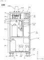
- the cleaning device 100 for a container includes at least a mounting table 10, a housing 20, an elastic member 30, a cleaning mechanism 40, and a control unit 50.
- the mounting table 10 includes a mounting face 11 that has formed therein an opening 10a which is capable facing the bottom portion 210 of the container 200 described hereinabove when the container is mounted on the mounting table 10 and which comes into contact with an upper edge (opening edge 230) of the circumferential wall portion 220.
- the material for the mounting table 10 of such a configuration as described above for example, a known synthetic resin material such as plastics, a metal material such as aluminum, and so forth can be exemplified.
- the mounting table 10 is mounted on a mounting plate 12 by known fixing member 13a such as a screw. Further, the mounting plate 12 is mounted on an upper portion of the elastic member 30 hereinafter described in such a manner as to be able to move upwardly and downwardly under an action of the elastic member 30.
- the mounting table 10 in the present embodiment is configured to be movable in the mounting direction of the container 200 by the elastic member 30 in a state in which it is mounted on the mounting plate 12 described hereinabove. It is to be noted that, in the present embodiment, if an operator presses the container 200 against the mounting table 10 along a downward direction of the vertical direction (direction of the gravity), then the mounting table 10 mounted on the mounting plate 12 is moved in the mounting direction described above (that is, in the direction of the gravity).
- the mounting face 11 is a funnel-shaped (funnel-type) face from a circumferential edge 10b toward the opening 10a like a conical face such that the opening 10a described above is positioned at the bottom (lowest position in the direction of the gravity). Consequently, it becomes possible for the cleaning liquid or foreign matters adhering to the mounting face 11 to flow into the opening 10a by an action of the gravity, and also a centering function when the beverage container 200 is mounted can be demonstrated.
- beverage containers 200 having, for example, different specifications (for example, of the height, the diameter of the opening edge 230, and so forth).
- the surface of the mounting face 11 in the present embodiment may be subject to a known liquid-repellent process for causing it to exhibit liquid repellency against the cleaning liquid and foreign matters described above.
- a liquid-repellent process for example, a fluorination process for fluorinating the surface, a process of applying a fluorine membrane, and so forth can be exemplified.
- the housing 20 is configured to have a function for mounting the elastic member 30 hereinafter described thereon and supporting the mounting table 10 described hereinabove for movement in the mounting direction (in the figures, in the Z direction). More specifically, as the housing 20 in the present embodiment, a frame member of a hollow rectangular parallelepiped shape capable of mounting thereon the mounting table 10 or the cleaning mechanism 40 or control unit 50 hereinafter described can be exemplified.
- the material for the housing 20 of such a configuration as described above is not specifically restricted insofar as it has the strength and durability sufficient to mount thereon the mounting table 10 described above or an air tank, a liquid storage tank, or the like hereinafter described, and, for example, a known metal material such as steel or aluminum and synthetic resin such as engineering plastics can be exemplified.
- the mounting table 10 in the present embodiment may be formed reusing a resin beverage container cleaned, for example, by the cleaning device 100 or the like.
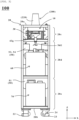
- the housing 20 in the present embodiment is partitioned, between an upper portion 20a that corresponds to a frame upper face and a bottom portion 20b that corresponds to a frame bottom face, into an upper stage section 20c, a middle stage section 20d, and a lower stage section 20e in order from the upper portion 20a as depicted in FIGS. 1 to 3 .
- the bottom face side of the bottom portion 20b preferably has provided thereon at least fixed legs 23 for fixing the mounting position of the housing 20 or known casters 24 for allowing the housing 20 to move in a horizontal direction.
- an installation opening 21 for allowing the mounting table 10 to be installed at the upper portion 20a of the housing 20 therethrough is formed as apparent from FIGS. 1 and 5 .
- a removable water-conveyance frame wall 22 which introduces cleaning liquid for cleaning the container 200 to the mounting face 11 without allowing the cleaning liquid to be scattered around the housing.
- a liquid storage tank 60 mounted on the housing 20 and capable of storing cleaning liquid therein is installed on the housing 20 and capable of storing cleaning liquid therein.
- a waste liquid tank 70 which is mounted on the housing 20 and is capable of storing therein cleaning liquid collected by a cleaning liquid collecting section 43 hereinafter described and containing foreign matters therein.
- the housing 20 preferably has provided thereon an air tank mounting section that extends between the middle stage section 20d and the lower stage section 20e described hereinabove and is capable of mounting thereon an air tank 51 into which compressed air can be stored.
- a water-conveyance frame wall 22 as described above for example, a bowl-shaped circumferential frame member made of metal or resin and open at the bottom thereof can be exemplified.
- the water-conveyance frame wall 22 being installed along the periphery of the installation opening 21, the cleaning liquid and foreign matters that have scattered around the housing can efficiently flow into the cleaning liquid collecting section 43.
- the water-conveyance frame wall 22 is fixed to the housing 20 by known fixtures 22a such as bolts as depicted in FIG. 5 . Accordingly, in the present embodiment, the water-conveyance frame wall 22 to which contaminants adhere can be removed from the housing 20 easily, and this can improve the maintenance performance.
- the elastic member 30 is configured to have a function for being mounted on the housing 20 described hereinabove and biasing the mounting table 10 along the mounting direction (in the present embodiment, in the Z direction that is also the vertical direction). More specifically, as recognized from FIGS. 1 , 2 , and 5 , as the elastic member 30, there can be exemplified a known spring member which is mounted at a base end portion thereof on the upper stage section 20c of the housing 20 and is connected at an upper end portion thereof to the mounting table 10.
- a known spring member is exemplified as an example of the elastic member 30, a different known elastic member such as a rubber member, for example, may be applied instead.
- the form of the elastic member 30 is not restricted to a form in which an elastic member is applied, and as another form of the elastic member 30, the elastic member 30 may include, for example, a known electrically driven actuator such as a hydraulic cylinder or a pneumatic cylinder connected to an unillustrated power supply insofar as it has the function described above.
- a known electrically driven actuator such as a hydraulic cylinder or a pneumatic cylinder connected to an unillustrated power supply insofar as it has the function described above.
- a spring member as the elastic member 30 as a spring member as the elastic member 30, a total of four spring members are provided in the upper stage section 20c in a corresponding relation with the four corners of the mounting table 10, if it is possible to stably move up or down the mounting table 10, then the number of spring members is not limited to four, and for example, three spring members may be provided or otherwise one or two spring members may be provided with a known guide used for guidance.
- the cleaning mechanism 40 is configured in such a manner as to be mounted on the housing 20 described above and to have a function for jetting cleaning liquid on the inner faces 220a of the bottom portion 210 and the circumferential wall portion 220 of the beverage container 200 by at least partly protruding in the opening 10a described hereinabove.
- the cleaning liquid preferable in the present embodiment is not specifically restricted if it can remove foreign matters described hereinabove, and, for example, tap water, known alcohol-containing water, and so forth can be exemplified.
- the cleaning mechanism 40 in the present embodiment includes a cleaning liquid discharging section 41 for discharging cleaning liquid described hereinabove and a compressed air discharging section 42 from which part of compressed air supplied from the air tank 51 hereinafter described is discharged. Further, as depicted in FIG. 5 and other figures, the cleaning mechanism 40 in the present embodiment includes the cleaning liquid collecting section 43 that collects cleaning liquid discharged from the cleaning liquid discharging section 41 described above and a main body portion 44 on which the cleaning liquid discharging section 41, the compressed air discharging section 42, and so forth are mounted.
- the main body portion 44 of the cleaning mechanism 40 is connected to the mounting table 10 and the mounting plate 12 by known fastening member 13b such as screws.
- the compressed air discharging section 42 in the present embodiment includes, as depicted in FIG. 7 and other figures, a known flow path along which compressed air can flow, and an air nozzle 42N that is disposed around the cleaning liquid discharging section 41 and that has a discharge port for compressed air directed toward the inner face 220a of the circumferential wall portion 220. More particularly, the air nozzle 42N in the present embodiment includes a plurality of air nozzles 42N (first air nozzle 42Na and second air nozzle 42Nb) disposed intermittently surrounding the cleaning liquid discharging section 41 described hereinabove.
- the compressed air discharging section 42 is not necessarily essential, and, for example, if a draining process after cleaning of a container is made unnecessary, then the compressed air discharging section 42 may be omitted suitably (the same applies in the second embodiment).
- the present embodiment exemplifies the two air nozzles 42N described above, three or more optional air nozzles 42N may be installed insofar as the restriction on the space is satisfied. Further, if it is possible to generate such an ascending swirling flow hereinafter described with which foreign matters and cleaning liquid can be removed, then a plurality of air nozzles 42N may not necessarily be provided, and a form in which only a single air nozzle 42N is provided may be applied. Further, the specific structure of such an air nozzle as described above is not restricted specifically if it can jet air from the discharge port described above, and known various nozzle parts can be applied, for example, by applying a known air nozzle or using a grease nipple.
- the discharge port of the air nozzle 42N described hereinabove is provided in such a manner as to be directed diagonally upwardly with respect to the installation plane of the air nozzle 42N (in the present example, on the outer side in a diametrical direction opposite to the cleaning liquid discharging section 41 and vertically upwardly) such that, as depicted in FIG. 7 , the compressed air described hereinabove forms a spiral flow ascending up to the bottom portion 210 along the inner face 220a of the circumferential wall portion 220 of the beverage container 200 (in the present embodiment, the air flow in the beverage container at the time of cleaning is referred to also as an "ascending spiral flow").
- This makes it possible to efficiently remove the cleaning liquid and foreign matters remaining in the inside of the beverage container 200 and collect them by the cleaning liquid collecting section 43 hereinafter described.
- the installation height of the discharge port is set such that an ascending swirling flow generated by the air nozzle 42N is brought into contact first with a portion of the inner face 220a of the circumferential wall portion 220 in the proximity of the opening edge 230. This makes it possible to efficiently remove foreign matters adhering to a portion of the beverage container 200 in the proximity of the tap (opening edge 230).
- the cleaning liquid discharging section 41 in the present embodiment is configured including, as depicted in FIGS. 5 and 6 and other figures, a known flow path along which cleaning liquid can pass and a cleaning liquid nozzle 41z that is disposed such that the height thereof from the mounting face described hereinabove is greater than that of the air nozzle 42N described hereinabove and jets cleaning liquid therefrom.
- the specific mechanism of such a cleaning liquid nozzle 41z as just described is not restricted specifically if it can jet the cleaning liquid from the discharge port, and, for example, there can be exemplified various known rotating nozzles which can discharge cleaning liquid while being rotated, for example, by jetting reaction force of the cleaning liquid.
- a rotating nozzle which includes, as depicted in FIG. 6 , a first discharge port 41a that discharges part of cleaning liquid toward the bottom portion 210 of the beverage container 200 and a second discharge port 41b that discharges the remaining part of the cleaning liquid along the inner face 220a of the circumferential wall portion 220.
- a plurality of second discharge ports 41b are provided intermittently along a circumferential direction of the cleaning liquid nozzle 41z (in the present embodiment, three second discharge ports 41b are provided in a circumferential direction).
- the cleaning liquid nozzle 41z is attached for rotation to a base portion 41e through a known bearing 41c and a collar 41d each formed of stainless steel. Furthermore, the base portion 41e to which the cleaning liquid nozzle 41z is attached is attached to the main body portion 44 through known fastening member Fx such as screws, for example.
- the cleaning liquid nozzle 41z can jet cleaning liquid from the second discharge port 41b while rotating with respect to the circumferential wall portion 220 together with jetting of cleaning liquid to the bottom portion 210 from the first discharge port 41a, and can exhibit high cleansing power for the beverage container 200.
- the cleaning mechanism 40 in the present embodiment further includes, as depicted in FIG. 5 , the cleaning liquid collecting section 43 for collecting the cleaning liquid containing foreign matters that has been jetted to the inner faces 220a of the bottom portion 210 and the circumferential wall portion 220 of the beverage container 200.
- the cleaning liquid collecting section 43 in the present embodiment includes, as depicted in FIG. 7 , a collecting hole disposed around the cleaning liquid discharging section 41 described hereinabove and connected to the waste liquid tank 70 hereinafter described, a collecting cup 43g for receiving the cleaning liquid collected through the collecting hole, and so forth.
- the collecting cup 43g is connected to the waste liquid tank 70 described hereinabove by a collecting flow path 56E hereinafter described, such that cleaning liquid that has been used (in which also foreign matters are mixed) and received by the collecting cup 43g is collected by the waste liquid tank 70.
- the collecting hole in the present embodiment preferably includes a plurality of collecting holes 43a to 43f disposed intermittently around the cleaning liquid discharging section 41 to be disposed concentrically with the air nozzle 42N with respect to the cleaning liquid discharging section 41 as depicted in FIG. 7 . It is to be noted that, although, in the present embodiment, a total of six collecting holes are provided avoiding the air nozzle 42N, there may be applied an alternative form in which any number of collecting holes other than six are provided insofar as the restrictions on the installation number and the space of the air nozzles 42N are satisfied.
- the control unit 50 is configured to have a function for jetting cleaning liquid to the beverage container 200 through the cleaning mechanism 40 according to a movement of the mounting table 10 by a predetermined distance d in a state in which the upper edge (opening edge 230) of the beverage container 200 is mounted on the mounting face 11.
- control unit 50 in the present embodiment is configured to have a function for jetting cleaning liquid to the inner faces 220a of the bottom portion 210 and the circumferential wall portion 220 of the beverage container 200 when the mounting table 10 has moved down by the predetermined distance d (refer to FIG. 8 ) in the state described above.
- the predetermined distance d it can be set suitably according to the size of the mounting table 10 or the housing 20, and in the present embodiment, the stroke of approximately 5 to 10 mm can be set as an example.
- control unit 50 in the present embodiment includes the air tank 51 capable of storing the compressed air described hereinabove, a known compressor 52 that generates the compressed air, two on-off valves with a timer hereinafter described, a water suction pump 55 that sucks cleaning liquid from the liquid storage tank 60, and various valves hereinafter described.
- the compressor 52 in the present embodiment preferably is installed on the lower stage section 20e of the housing 20 from the point of view of noise suppression and so forth.
- the compressor 52 in the cleaning device 100 in the present embodiment includes two compressors of a first compressor 52A and a second compressor 52B, it may otherwise include a single compressor.
- the cleaning device 100 in the present embodiment is configured such that the compressed air generated by the compressor 52 is used to suck the cleaning liquid stored in the liquid storage tank 60 by the water suction pump 5, to jet the cleaning liquid to the inner faces 220a of the bottom portion 210 and the circumferential wall portion 220 of the beverage container 200 through the cleaning mechanism 40 described hereinabove.
- control unit 50 in the present embodiment further includes, as depicted in FIG. 4 and other figures, an on-off valve 53 with a first timer that stops supply of compressed air to be used for suction of the cleaning liquid described hereinabove and an on-off valve 54 with a second timer that stops supply of compressed air to be discharged toward the inner faces 220a of the bottom portion 210 and the circumferential wall portion 220 of the beverage container 200 through the compressed air discharging section 42.
- the person who drinks beverage can clean the inner face 220a of the beverage container 200 after drinking, by using the cleaning device 100 of the present embodiment.
- the person who drinks the beverage will first mount the beverage container 200 on the mounting table 10 with the opening edge 230 in contact with the mounting face 11 such that the bottom portion 210 of the beverage container 200 is directed vertically upwardly. Thereafter, the person who drinks the beverage will move the mounting table 10 vertically downwardly by the predetermined distance d in the state in which the opening edge 230 of the beverage container 200 is mounted on the mounting face 11 as depicted in FIG. 8 .
- a valve Vb for example, a known valve such as a mechanical valve can be exemplified
- the compressor 52 generates compressed air and supplies the compressed air to a first air flow path 56A and a second air flow path 56B through the air tank 51.
- compressed air flowing along the second air flow path 56B is supplied to the known water suction pump 55 (process pump), whereupon the cleaning liquid stored in the liquid storage tank 60 is sucked and flows along a cleaning liquid flow path 57 and is then supplied to the cleaning liquid discharging section 41.
- the water suction pump 55 is not specifically restricted insofar as it can operate with compressed air, and, for example, a reciprocating pump such as a known diaphragm pump and a rotating pump such as a gear pump can be applied.
- a diaphragm pump is applied as an example of the water suction pump 55.
- the cleaning liquid supplied to the cleaning liquid discharging section 41 is jetted toward the inner faces 220a of the bottom portion 210 and the circumferential wall portion 220 in the beverage container 200 from the first discharge port 41a and the second discharge port 41b of the cleaning liquid nozzle 41z as described hereinabove.
- the compressed air supplied to the first air flow path 56A is supplied to the compressed air discharging section 42 described hereinabove.
- the compressed air supplied to the compressed air discharging section 42 forms an ascending swirling flow through the air nozzle 42N (first air nozzle 42Na and second air nozzle 42Nb) and is jetted into the beverage container 200.
- the on-off valve 53 with a first timer and the on-off valve 54 with a second timer start clocking.
- stopping jetting of cleaning liquid from the cleaning liquid discharging section 41 based on the on-off valve 53 with a first timer and stopping jetting of compression air from the compressed air discharging section 42 based on the on-off valve 54 with a second timer are executed at such timings different from each other that the latter is performed later than the former in chronological order.
- the valve Vb described hereinabove is closed to stop the supply of compressed air from the compressor 52.
- the present embodiment is set such that, in a case where the user keeps the pressure through the beverage container 200, a stopping process of cleaning liquid and so forth through the on-off valve 53 with a first timer and the on-off valve 54 with a second timer described above is executed.
- the cleaning device 100 of the present embodiment after supply of cleaning liquid to the inner faces 220a of the bottom portion 210 and the circumferential wall portion 220 in the beverage container 200 through the on-off valve 53 with a first timer stops, supply of compressed air discharged toward the inner faces 220a of the bottom portion 210 and the circumferential wall portion 220 through the on-off valve 54 with a second timer is stopped.
- the cleaning device 100 of the present embodiment may further include a bypass flow path 56C that is branched from a bypass start point BP2 provided on the upstream side with respect to a branching point BP1 between the first air flow path 56A and the second air flow path 56B and is connected to a bypass merging point BP3 with the first air flow path 56A on the downstream side with respect to the branching point BP1.
- the bypass flow path 56C is preferably provided with a check valve Vr1 for preventing backflow of compressed air.
- a check valve Vr1 for preventing backflow of compressed air. It is to be noted that the structure of the check valve Vr1 is not restricted specifically if the function described above can be achieved, and various known check valves for gas may be applied.
- the cleaning device 100 With the cleaning device 100 according to the first embodiment described above, it is possible to use the compressed air generated by the compressor 52, as working fluid, to jet cleaning liquid and air from the cleaning mechanism 40 and clean the beverage container 200. Accordingly, only if, for example, a power supply of alternating current (AC) 100 V can be secured, then it is possible to relatively decrease the device scale without using an expensive control device such as a programmable logic controller (PLC), for example, to achieve space saving, maintenance saving, and cost reduction while it is possible to clean the inside of a container by jetting cleaning liquid to a container before disposal without allowing leakage of the cleaning liquid therearound through an operation by one hand. It is to be noted that it is also possible to reuse the beverage container 200 cleaned by the cleaning device 100 of the present embodiment, for example, for beverages or for some other use.
- AC alternating current
- PLC programmable logic controller
- the cleaning device 100 of the present embodiment can clean the beverage container 200 with a simple configuration as described above, by performing cleaning of containers with a hand not only of, for example, a store staff member of a shop or a container collecting company but also of a person who drinks the beverage, it is possible for them to be involved in environmental protection activities.
- the AC 100 V power supply described hereinabove may include a known secondary battery such as a lithium ion secondary battery or a lead acid battery, for example.
- the cleaning device 100 of the present embodiment includes the liquid storage tank 60 and the waste liquid tank 70 to ease constraints to the installation place, this form is not restrictive, and a form in which the cleaning device 100 is connected directly, for example, to a known waterway or drainage route may be applied.
- the discharge mode of cleaning liquid from the cleaning liquid discharging section 41 is not restricted to that described hereinabove and may be a mode in which, for example, functional water (as an example, micro bubble water in which micro bubbles generated by a known micro bubble generator of the ejector type or the cavitation type not depicted are added, ultrasonic water generated using an ultrasonic wave generator that can be driven by the power supply described hereinabove or the like) is used.
- functional water as an example, micro bubble water in which micro bubbles generated by a known micro bubble generator of the ejector type or the cavitation type not depicted are added
- ultrasonic water generated using an ultrasonic wave generator that can be driven by the power supply described hereinabove or the like
- a cleaning device 110 for a beverage container according to a second embodiment is described with reference to FIG. 9 . It is to be noted that components similar to those of the cleaning device 100 of the first embodiment described hereinabove are denoted by identical reference signs and overlapping description of them is suitably omitted.
- the cleaning device 110 for a beverage container uses a pump mechanism (diaphragm type pump) as a mechanism for delivering cleaning liquid to the cleaning liquid discharging section 41
- the cleaning device 110 of the present embodiment is characterized in that a cylinder mechanism (cylinder type drive pump 58) is used in place of the pump mechanism.
- a cylinder mechanism cylinder type drive pump 58
- the water suction pump 55 capable of being applied in the present invention not only a diaphragm type pump but also a known air-driven pump which can be driven by compressed air including a cylinder type drive pump 58 described in connection with the present embodiment can be applied.
- the cleaning device 110 for a beverage container in the present embodiment includes the cylinder type drive pump 58 in place of the diaphragm type pump in the configuration described hereinabove in connection with the cleaning device 100 of the first embodiment.
- the cylinder type drive pump 58 includes at least a cylinder tube 58a, a piston rod 58b, a biasing spring 58c, and a positioning stopper 58d. Further, the inside of the cylinder tube 58a and the cleaning liquid flow path 57 are connected to each other such that the cylinder type drive pump 58 receives cleaning liquid from the liquid storage tank 60 through the cleaning liquid flow path 57 and conveys the cleaning liquid to the cleaning mechanism 40.
- the cleaning liquid flow path 57 between the cleaning mechanism 40 and the cylinder tube 58a includes a check valve Vr 2 for preventing cleaning liquid flowing along the cleaning liquid flow path 57 from back-flowing to the inside of the cylinder tube 58a.
- the cleaning liquid flow path 57 between the liquid storage tank 60 and the cylinder tube 58a includes a check valve Vr 3 for preventing cleaning liquid flowing along the cleaning liquid flow path 57 from back-flowing to the liquid storage tank 60.
- the second air flow path 56B branched from the bypass start point BP1 is connected to a space in the cylinder tube 58a on the piston rod 58b side.
- the piston rod 58b has at one end thereof a known cylinder head (not depicted) to be movable in the cylinder tube 58a.
- the biasing spring 58c is provided between the other end of the piston rod 58b and the cylinder tube 58a such that it biases the other end of the piston rod 58b to push out the other end of the piston rod 58b toward the positioning stopper 58d.
- the cylinder tube 58a is set to be in a state of being filled with cleaning liquid (namely, the other end of the piston rod 58b is in contact with the positioning stopper 58d).
- part of the compressed air generated by the compressor 52 is branched at the bypass start point BP1 and is supplied to the space in the cylinder tube 58a on the piston rod 58b side.
- the one end of the piston rod 58b moves in such a manner as to push out the cleaning liquid in the cylinder tube 58a against the biasing force of the biasing spring 58c by an action of the compressed air. Consequently, the cleaning liquid in the cylinder tube 58a is delivered to the cleaning mechanism 40 through the cleaning liquid flow path 57. Further, after the cleaning liquid in the cylinder tube 58a is delivered, the other end of the piston rod 58b is moved toward the positioning stopper 58d by the restoring force of the biasing spring 58c.
- the one end of the piston rod 58b being moved by the action of the compressed air in such a manner as to push out the cleaning liquid in the cylinder tube 58a and the other end of the piston rod 58b being moved toward the positioning stopper 58d by the action of the restoring force of the biasing spring 58c are repeated during supply of the compressed air generated by the compressor 52.
- the cleaning liquid is supplied intermittently to the cleaning mechanism 40 from the liquid storage tank 60 through the cylinder type drive pump 58.
- the cleaning device 110 of the second embodiment can exhibit advantageous effects similar to those of the first embodiment described hereinabove.
- first embodiment and the second embodiment demonstrate an example in which a reciprocating pump is used to intermittently suck cleaning liquid from the liquid storage tank 60
- a different configuration which uses a different known air driven pump to intermittently suck cleaning liquid from the liquid storage tank 60 and deliver the cleaning liquid to the cleaning liquid discharging section 41.
- the mechanism for delivering cleaning liquid from the liquid storage tank 60 to the cleaning mechanism 40 there is applied an air driven pump which uses compressed air generated by the compressor 52 connected to a known power supply (commercial power supply or secondary battery).
- a known power supply commercial power supply or secondary battery
- the cleaning device 120 for a beverage container according to the present embodiment is characterized principally in including a toggle mechanism type drive pump 59 of the human power type that does not require any power supply nor any working fluid.
- the cleaning device 120 for a beverage container includes the toggle mechanism type drive pump 59 in place of the cylinder type drive pump 58 in addition to the configuration described hereinabove in connection with the cleaning device 110 of the second embodiment.
- the toggle mechanism type drive pump 59 includes at least a toggle link 59a, a cylinder tube 59b, a piston rod 59c, a biasing spring 59d, and a connection member 59e that connects the toggle link 59a and the piston rod 59c to each other.
- the inside of the cylinder tube 59b and the cleaning liquid flow path 57 are connected to each other by check valves Vr 2 and Vr 3 such that the toggle mechanism type drive pump 59 can receive cleaning liquid from the liquid storage tank 60 through the cleaning liquid flow path 57 and delivers the cleaning liquid to the cleaning mechanism 40.
- a first joint 59a 1 (which preferably is such a roller as depicted in FIG. 10 ) is installed in such a manner as to support the bottom face of the mounting plate 12 described hereinabove for movement; a second joint 59a 2 is fixedly installed on a wall face of the ceiling or the like; and a third joint 59a 3 is connected to the other and of the piston rod 59c through the connection member 59e as described hereinabove.
- first joint 59a 1 makes it possible also for the first joint 59a 1 to move downwardly together with the mounting plate 12 in an interlocking relation with a downward movement of the mounting table 10 when the user (a person who drinks the beverage or the like) moves the mounting table 10 vertically downwardly by the predetermined distance d.
- the cylinder tube 59b is set to be in a state of being filled with cleaning liquid (that is, the other end of the piston rod 59c is at an upper limit position in the vertical upward direction).
- the one end of the piston rod 59c moves in such a manner as to push out the cleaning liquid in the cylinder tube 59b against the biasing force of the biasing spring 59d by the action of the boosted movement of the third joint 59a 3 . Consequently, the cleaning liquid in the cylinder tube 59b is delivered to the cleaning mechanism 40 through the cleaning liquid flow path 57.
- the cleaning device 120 of the third embodiment can exhibit advantageous effects similar to those of the first embodiment described hereinabove. Moreover, in the third embodiment, since no power supply and no compressed air are required for delivery of cleaning liquid, the device cost can be suppressed significantly while the cleaning function for a beverage container is maintained.
- the present invention can be used in manufacturing a cleaning device that is capable of efficiently cleaning a container to which foreign matters such as leftovers, for example, have adhered, with a simple configuration, in a small shop or at home.
Landscapes
- Engineering & Computer Science (AREA)
- Mechanical Engineering (AREA)
- Cleaning In General (AREA)
- Cleaning By Liquid Or Steam (AREA)
- Devices For Dispensing Beverages (AREA)
Applications Claiming Priority (2)
| Application Number | Priority Date | Filing Date | Title |
|---|---|---|---|
| JP2021119816 | 2021-07-20 | ||
| PCT/JP2022/004599 WO2023002649A1 (fr) | 2021-07-20 | 2022-02-07 | Dispositif de nettoyage pour récipient |
Publications (3)
| Publication Number | Publication Date |
|---|---|
| EP4374976A1 true EP4374976A1 (fr) | 2024-05-29 |
| EP4374976A4 EP4374976A4 (fr) | 2025-06-25 |
| EP4374976B1 EP4374976B1 (fr) | 2026-05-06 |
Family
ID=84979074
Family Applications (1)
| Application Number | Title | Priority Date | Filing Date |
|---|---|---|---|
| EP22845590.3A Active EP4374976B1 (fr) | 2021-07-20 | 2022-02-07 | Dispositif de nettoyage pour récipient |
Country Status (3)
| Country | Link |
|---|---|
| EP (1) | EP4374976B1 (fr) |
| JP (1) | JP7505126B2 (fr) |
| WO (1) | WO2023002649A1 (fr) |
Families Citing this family (1)
| Publication number | Priority date | Publication date | Assignee | Title |
|---|---|---|---|---|
| CN116689411A (zh) * | 2023-06-09 | 2023-09-05 | 浙江省缙云县三鼎实业有限公司 | 一种缸体的表面处理装置 |
Family Cites Families (11)
| Publication number | Priority date | Publication date | Assignee | Title |
|---|---|---|---|---|
| JPS57194455U (fr) | 1981-06-06 | 1982-12-09 | ||
| JPS58177074U (ja) * | 1982-05-24 | 1983-11-26 | 星崎電機株式会社 | コツプ洗滌装置 |
| JPH1072275A (ja) * | 1996-08-29 | 1998-03-17 | Super Silicon Kenkyusho:Kk | ルツボ洗浄乾燥装置 |
| JP2007075703A (ja) | 2005-09-13 | 2007-03-29 | Mitsubishi Heavy Industries Food & Packaging Machinery Co Ltd | ロータリー洗浄装置、ロータリー殺菌装置、飲料水充填ライン、及び同ラインの不良容器除去方法 |
| KR20080016285A (ko) * | 2006-08-18 | 2008-02-21 | 서정현 | 컵 세척기 |
| JP5449967B2 (ja) * | 2009-10-05 | 2014-03-19 | 日立アロカメディカル株式会社 | ノズル洗浄ユニット |
| KR101568830B1 (ko) * | 2014-09-12 | 2015-11-13 | 심성주 | 컵 세척장치 |
| JP2017051904A (ja) | 2015-09-09 | 2017-03-16 | 凸版印刷株式会社 | 容器洗浄機および容器の洗浄方法 |
| US20180092505A1 (en) * | 2016-10-03 | 2018-04-05 | Liquid Integrity, LLC | Portable fluid dispensing and rinsing system |
| KR102048655B1 (ko) * | 2019-04-24 | 2019-11-25 | 김홍성 | Dsa전극을 이용한 개인용 컵 자동 살균세척장치 |
| KR20210069541A (ko) * | 2019-12-03 | 2021-06-11 | 주식회사 워터제네시스 | 수돗물을 이용한 개인 컵 자동 살균세척 장치 |
-
2022
- 2022-02-07 EP EP22845590.3A patent/EP4374976B1/fr active Active
- 2022-02-07 JP JP2023536325A patent/JP7505126B2/ja active Active
- 2022-02-07 WO PCT/JP2022/004599 patent/WO2023002649A1/fr not_active Ceased
Also Published As
| Publication number | Publication date |
|---|---|
| EP4374976A4 (fr) | 2025-06-25 |
| EP4374976B1 (fr) | 2026-05-06 |
| JP7505126B2 (ja) | 2024-06-24 |
| JPWO2023002649A1 (fr) | 2023-01-26 |
| WO2023002649A1 (fr) | 2023-01-26 |
Similar Documents
| Publication | Publication Date | Title |
|---|---|---|
| US7635097B2 (en) | Automated cleansing sprayer having separate cleanser and air vent paths from bottle | |
| US6971549B2 (en) | Bottle adapter for dispensing of cleanser from bottle used in an automated cleansing sprayer | |
| EP1467820B1 (fr) | Pulverisateur automatise de nettoyage | |
| KR101697174B1 (ko) | 마이크로 버블 세척기 | |
| WO2008142944A1 (fr) | Procédé de nettoyage d'une buse, dispositif de nettoyage d'une buse et analyseur automatique | |
| JP2011078881A (ja) | ノズル洗浄ユニット | |
| EP4374976B1 (fr) | Dispositif de nettoyage pour récipient | |
| WO2016111648A1 (fr) | Lave-vaisselle compact | |
| EP4446017A2 (fr) | Système de lavage d'aérographes | |
| KR101990522B1 (ko) | 컵자동 세척장치의 컵세척 유닛 | |
| WO2008113070A2 (fr) | Système de nettoyage et procédé d'utilisation | |
| JP7821618B2 (ja) | 容器の洗浄装置 | |
| KR100837222B1 (ko) | 컵 자동 세척기 | |
| JP2023026253A (ja) | 容器の洗浄装置 | |
| US20240180359A1 (en) | Method for cleaning and/or disinfecting and/or rinsing a milk-conducting system of a coffee machine, and associated cleaning device | |
| JP2013146719A (ja) | 洗浄装置および洗浄方法 | |
| CN204320765U (zh) | 一种产品回收和冲洗装置 | |
| CN1984816A (zh) | 泡沫分配器 | |
| CN207943198U (zh) | 氧氟沙星滴眼液定量包装机 | |
| KR101621531B1 (ko) | 삼투압을 이용한 분사장치 | |
| CN212789214U (zh) | 一种液体食品包装机械的吸嘴灭菌装置 | |
| JP2011245444A (ja) | 洗浄装置 | |
| JP2018083133A (ja) | ディスペンサ | |
| CN108882802A (zh) | 废物处理单元 | |
| JP2005342389A (ja) | 食器洗い機 |
Legal Events
| Date | Code | Title | Description |
|---|---|---|---|
| STAA | Information on the status of an ep patent application or granted ep patent |
Free format text: STATUS: THE INTERNATIONAL PUBLICATION HAS BEEN MADE |
|
| PUAI | Public reference made under article 153(3) epc to a published international application that has entered the european phase |
Free format text: ORIGINAL CODE: 0009012 |
|
| STAA | Information on the status of an ep patent application or granted ep patent |
Free format text: STATUS: REQUEST FOR EXAMINATION WAS MADE |
|
| 17P | Request for examination filed |
Effective date: 20240119 |
|
| AK | Designated contracting states |
Kind code of ref document: A1 Designated state(s): AL AT BE BG CH CY CZ DE DK EE ES FI FR GB GR HR HU IE IS IT LI LT LU LV MC MK MT NL NO PL PT RO RS SE SI SK SM TR |
|
| DAV | Request for validation of the european patent (deleted) | ||
| DAX | Request for extension of the european patent (deleted) | ||
| REG | Reference to a national code |
Ref country code: DE Ref legal event code: R079 Free format text: PREVIOUS MAIN CLASS: B08B0003020000 Ipc: B08B0009080000 Ref country code: DE Ref legal event code: R079 Ref document number: 602022036545 Country of ref document: DE Free format text: PREVIOUS MAIN CLASS: B08B0003020000 Ipc: B08B0009080000 |
|
| A4 | Supplementary search report drawn up and despatched |
Effective date: 20250526 |
|
| RIC1 | Information provided on ipc code assigned before grant |
Ipc: A47L 15/00 20060101ALI20250520BHEP Ipc: B08B 9/08 20060101AFI20250520BHEP |
|
| GRAP | Despatch of communication of intention to grant a patent |
Free format text: ORIGINAL CODE: EPIDOSNIGR1 |
|
| STAA | Information on the status of an ep patent application or granted ep patent |
Free format text: STATUS: GRANT OF PATENT IS INTENDED |
|
| RIC1 | Information provided on ipc code assigned before grant |
Ipc: B08B 9/08 20060101AFI20251216BHEP Ipc: A47L 15/00 20060101ALI20251216BHEP |
|
| INTG | Intention to grant announced |
Effective date: 20260109 |
|
| GRAS | Grant fee paid |
Free format text: ORIGINAL CODE: EPIDOSNIGR3 |
|
| GRAA | (expected) grant |
Free format text: ORIGINAL CODE: 0009210 |
|
| STAA | Information on the status of an ep patent application or granted ep patent |
Free format text: STATUS: THE PATENT HAS BEEN GRANTED |