EP4374985A2 - Dispositif de pose - Google Patents
Dispositif de pose Download PDFInfo
- Publication number
- EP4374985A2 EP4374985A2 EP24169125.2A EP24169125A EP4374985A2 EP 4374985 A2 EP4374985 A2 EP 4374985A2 EP 24169125 A EP24169125 A EP 24169125A EP 4374985 A2 EP4374985 A2 EP 4374985A2
- Authority
- EP
- European Patent Office
- Prior art keywords
- guide
- prestressing
- setting device
- guide device
- insulating
- Prior art date
- Legal status (The legal status is an assumption and is not a legal conclusion. Google has not performed a legal analysis and makes no representation as to the accuracy of the status listed.)
- Granted
Links
Images


Classifications
-
- B—PERFORMING OPERATIONS; TRANSPORTING
- B21—MECHANICAL METAL-WORKING WITHOUT ESSENTIALLY REMOVING MATERIAL; PUNCHING METAL
- B21J—FORGING; HAMMERING; PRESSING METAL; RIVETING; FORGE FURNACES
- B21J15/00—Riveting
- B21J15/10—Riveting machines
- B21J15/28—Control devices specially adapted to riveting machines not restricted to one of the preceding subgroups
-
- B—PERFORMING OPERATIONS; TRANSPORTING
- B25—HAND TOOLS; PORTABLE POWER-DRIVEN TOOLS; MANIPULATORS
- B25B—TOOLS OR BENCH DEVICES NOT OTHERWISE PROVIDED FOR, FOR FASTENING, CONNECTING, DISENGAGING, OR HOLDING
- B25B23/00—Details of, or accessories for, spanners, wrenches, screwdrivers
- B25B23/02—Arrangements for handling screws or nuts
- B25B23/08—Arrangements for handling screws or nuts for holding or positioning screw or nut prior to or during its rotation
- B25B23/10—Arrangements for handling screws or nuts for holding or positioning screw or nut prior to or during its rotation using mechanical gripping means
-
- B—PERFORMING OPERATIONS; TRANSPORTING
- B21—MECHANICAL METAL-WORKING WITHOUT ESSENTIALLY REMOVING MATERIAL; PUNCHING METAL
- B21J—FORGING; HAMMERING; PRESSING METAL; RIVETING; FORGE FURNACES
- B21J15/00—Riveting
- B21J15/02—Riveting procedures
- B21J15/025—Setting self-piercing rivets
-
- B—PERFORMING OPERATIONS; TRANSPORTING
- B21—MECHANICAL METAL-WORKING WITHOUT ESSENTIALLY REMOVING MATERIAL; PUNCHING METAL
- B21J—FORGING; HAMMERING; PRESSING METAL; RIVETING; FORGE FURNACES
- B21J15/00—Riveting
- B21J15/10—Riveting machines
- B21J15/16—Drives for riveting machines; Transmission means therefor
-
- B—PERFORMING OPERATIONS; TRANSPORTING
- B21—MECHANICAL METAL-WORKING WITHOUT ESSENTIALLY REMOVING MATERIAL; PUNCHING METAL
- B21J—FORGING; HAMMERING; PRESSING METAL; RIVETING; FORGE FURNACES
- B21J9/00—Forging presses
- B21J9/02—Special design or construction
-
- B—PERFORMING OPERATIONS; TRANSPORTING
- B21—MECHANICAL METAL-WORKING WITHOUT ESSENTIALLY REMOVING MATERIAL; PUNCHING METAL
- B21J—FORGING; HAMMERING; PRESSING METAL; RIVETING; FORGE FURNACES
- B21J9/00—Forging presses
- B21J9/10—Drives for forging presses
-
- B—PERFORMING OPERATIONS; TRANSPORTING
- B23—MACHINE TOOLS; METAL-WORKING NOT OTHERWISE PROVIDED FOR
- B23P—METAL-WORKING NOT OTHERWISE PROVIDED FOR; COMBINED OPERATIONS; UNIVERSAL MACHINE TOOLS
- B23P19/00—Machines for simply fitting together or separating metal parts or objects, or metal and non-metal parts, whether or not involving some deformation; Tools or devices therefor so far as not provided for in other classes
- B23P19/02—Machines for simply fitting together or separating metal parts or objects, or metal and non-metal parts, whether or not involving some deformation; Tools or devices therefor so far as not provided for in other classes for connecting objects by press fit or for detaching same
- B23P19/027—Machines for simply fitting together or separating metal parts or objects, or metal and non-metal parts, whether or not involving some deformation; Tools or devices therefor so far as not provided for in other classes for connecting objects by press fit or for detaching same using hydraulic or pneumatic means
-
- B—PERFORMING OPERATIONS; TRANSPORTING
- B21—MECHANICAL METAL-WORKING WITHOUT ESSENTIALLY REMOVING MATERIAL; PUNCHING METAL
- B21J—FORGING; HAMMERING; PRESSING METAL; RIVETING; FORGE FURNACES
- B21J15/00—Riveting
- B21J15/38—Accessories for use in connection with riveting, e.g. pliers for upsetting; Hand tools for riveting
- B21J15/42—Special clamping devices for workpieces to be riveted together, e.g. operating through the rivet holes
Definitions
- the present invention relates to a setting device for fastening an element to a workpiece.
- setting devices are often used to attach elements to them that provide certain functions.
- Such elements can be, for example, nut or bolt elements that serve as attachment points for other components.
- Such elements are used, for example, when it comes to attaching fasteners to sheet metal parts.
- a typical area of application for such seating devices is automobile construction. But seating devices are also widely used in other areas.
- the WO94/15736 A1 discloses a fastening machine according to the preamble of claim 1I 2 having a rivet feed channel in which a rivet head is engaged with spring-loaded balls to align the rivet with the rivet feed channel and a punch.
- the setting device is provided with a guide device that guides the element safely and in the correct position during the bringing in and pressing.
- the guide device has an axial cavity through which the element is guided in a setting direction - i.e. towards the workpiece - by means of the axially movable stamp.
- the guide device has at least two guide elements that define the cavity or limit it in a radial direction.
- the pretensioning device comprises at least one elastic pretensioning element that generates the pretensioning force and is made at least partially from an elastomer.
- a pretensioning element can be produced cost-effectively and provides the required preload force reliably and reproducibly.
- the prestressing element is a circumferentially closed, in particular annular element that surrounds the guide elements on their radial outer side in the circumferential direction.
- it can have any circumferential and/or cross-sectional geometry, e.g. a rectangular, square, circular or oval circumferential and/or cross-sectional geometry.
- the pre-tensioning element can have a contact section that is arranged on the guide device, in particular fastened or molded on, and that projects in at least one section of the guide device in the radial direction beyond an outer contour of the guide elements.
- the contact section can be arranged on a component of the setting device that at least partially accommodates the guide device, in particular on a housing section, in particular fastened or molded on, with the contact section protruding radially inward.
- a further embodiment which can also be combined with the embodiments described above, provides that the pre-tensioning element is a separate component with a contact section that is arranged in the radial direction between the guide device and a component of the setting device that at least partially accommodates the guide device, in particular a housing section.
- Such a contact section forms at least one support point for radial support of the guide direction. It can also be provided on a pre-tensioning element surrounding the guide elements in the circumferential direction or be formed by this element itself or - as mentioned - be an independent functional component.
- the contact section is arranged on a radial outer side of one of the guide elements.
- contact sections can be provided, which are distributed, in particular symmetrically distributed, in the circumferential direction of the guide device and/or in the circumferential direction of a component of the setting device that at least partially accommodates the guide device. This enables uniform support of the guide device and is easy to implement in terms of manufacturing technology.
- the contact sections can be designed separately from one another.
- adjacent guide elements in the circumferential direction are separated from one another by at least one interruption, for example by a slot.
- the guide elements are electrically insulated from one another. This is particularly advantageous when the guide elements (or parts thereof) themselves act as electrical contacts.
- At least one insulating element is arranged in the interruption, in particular wherein the insulating element comprises an electrically insulating and/or elastic material or is made entirely from it.
- the insulating element can essentially completely fill the interruption. However, partial filling is sufficient in many cases.
- the insulating element preferably comprises an elastomer or is made entirely from an elastomer. It can have a circular, oval, trapezoidal or wedge-shaped cross-section.
- the geometry of the insulating element can be essentially constant in the longitudinal direction of the insulating element. However, a geometry that varies in the longitudinal direction is also conceivable.
- the geometry of the prestressing element can also be adapted to the respective requirements. According to the invention, it is essentially constant in the circumferential direction of the prestressing element.
- the prestressing element and/or the insulating element may comprise a vulcanized elastomeric plastic or be formed entirely thereof.
- the pre-tensioning element and the insulating element are made as one piece. In principle, however, they can also be manufactured separately. Both the pre-tensioning element and the insulating element can be multi-piece components.
- the prestressing element and/or the insulating element are at least partially formed onto the guide device, in particular onto at least one of the guide elements.
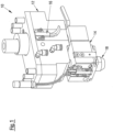
- Fig.1 shows a setting device 10 in a perspective view.
- This comprises a guide housing 12 and a guide plate 14.
- the setting device 10 has a sensor 16 with which it can be monitored whether the setting device 10 is in a closed or open state.
- a base plate 18 is arranged on the guide plate 14 and can be brought into contact with a workpiece in order to fasten a fastening element to it.
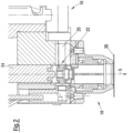
- Fig.2 shows a cross section through a part of the guide plate 14 and through the base plate 18.
- the guide plate 14 has a feed channel 20 through which the fastening element 22 to be fastened to the workpiece can be brought into a position from which it can be pressed towards and into the workpiece by a punch or ram 24 movable in a setting direction S.
- a starting situation/position is shown in which the element 22 is clamped by means of a holding finger.
- the setting device 10 is opened and the element 22 can be processed.
- the base plate 18 has already been brought into contact with a surface of a workpiece 36 to which the element 22 is to be attached. It is understood that the workpiece 36 shown as a sheet metal part by way of example can also be designed differently. The same applies to the element 22.
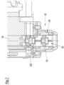
- the guide device 28 comprises a plurality of guide segments 30A, 30B.
- the segments 30A, 30B are separate components separated from one another by a slot 39, each of which has a circular segment-like cross-section and is arranged in such a way that it delimits the cavity 26 in the circumferential direction. They are held in a prestressing position by a prestressing device (not shown in detail).
- the segments 30A, 30B are prestressed in the direction of a longitudinal axis 32H of the cavity 26, which is arranged coaxially with a longitudinal axis 32S of the punch 24, i.e. radially inward. As soon as the element 22 enters the cavity 26, the segments 30A, 30B are pressed outward against the prestressing force generated by the prestressing device.
- Fig.4 shows how the element 22 is pushed through the cavity 26 of the guide device 28.
- a peripheral surface 34 of the element 22 interacts with the segments 30A, 30B.
- the pre-tensioning force ensures reliable guidance of the element 22, since the risk of the element 22 tipping or jamming is minimized.
- Fig.5 shows how the element 22 is pressed into the workpiece 36, which is only indicated.
- the element 22 is a self-punching element.
- a forming of a rivet section 38 of the element 22 is not shown, which can be brought about by the action of a die (not shown).
- the formed rivet section 38 engages behind the workpiece 38 on its rear side.
- a punching slug (not shown) has been removed.
- the setting device 10 can in principle also be used for non-self-punching elements 22.
- the workpiece 36 is then pre-punched in a suitable manner.
- Fig.6 shows the "normal case": After fastening the element 22 to the workpiece 36, the setting device 10 is removed from it and brought into a new setting position. This can be done by moving the setting device 10 or by moving the workpiece 36. Both the setting device 10 and the workpiece 36 can also be moved or a new workpiece 36 can be brought in. A new element 22 has already been brought into the starting position, which is also in Fig. 2 has already been shown.
- Fig.7 shows a malfunction of the setting device 10.
- the first element 22 is still in the area of the guide device 28, for example because it has become jammed there, and blocks the cavity 26 provided for guiding the element 22.
- the second element 22, which has already been brought into the starting position, would now be pressed against the first element 22 by the stamp 24, which would most likely result in damage to the setting device 10, in particular the guide device 28.
- a detection device is provided by means of which the presence of an element 22 in the cavity 26 can be detected.
- An embodiment of such a detection device is shown in Fig.8 It is integrated into the guide device 28, the components of which are Fig.9 shown in an exploded view.
- the guide device 28 comprises four guide segments 30A, 30B, 30C, 30D (preferably made of metal), each of which forms a peripheral section of the cavity 26. They are separated from one another by insulating pins 40 which are arranged in slots 39 provided between adjacent guide segments 30A, 30B, 30C, 30D (see e.g. Fig.3 , 10A, 10B ).
- the insulating pins 40 can be made of an elastomer. They electrically insulate adjacent segments 30A, 30B, 30C, 30D and, due to their elastic properties, enable a relative movement of the segments 30A, 30B, 30C, 30D.
- elastic rings 42A, 42B, 42C (e.g. O-rings) are provided. They lie in appropriately dimensioned grooves 44.
- the segments 30A, 30B, 30C, 30D are prestressed radially inwards against the elastic insulating pins 40 by the rings 42A, 42B, 42C.
- the rings 42A, 42B, 42C are stretched by introducing an element 22 into the cavity 26. Ultimately, this generates a force acting on the element 22 in the radial direction, which stabilizes the position of the element 22.
- the electrically conductive segments 30A and 30B are connected to electrical conductors 46A, 46B. These allow a voltage to be applied between the elements 30A, 30B by means of a control device. If the element 22 is electrically conductive, it short-circuits the segments 30A, 30B as soon as it enters the cavity 26, so that a current can flow, which is detected by the control device. In principle, it is also possible to determine the presence of the element 22 in an analogous manner via a resistance measurement or other electrical parameters.
- Axial support of the guide device 28 or the segments 30A, 30B, 30C, 30D in a housing 18A of the plate 18 is provided by an electrically insulating support ring 45.
- Radial support can be provided by the rings 42A, 42C, since these partially protrude from the grooves 44 and thus protrude beyond the segments 30A, 30B, 30C, 30D in the radial direction.
- FIGS. 10A to 10D show a further embodiment of the guide device 28, wherein Fig. 10A is a perspective view and the Fig. 10B to 10D Cross-sections or longitudinal sections.
- the rings 42A, 42B, 42C and the insulating pins 40 are formed in one piece. They can also be simply connected to one another or be separate components. According to a particularly simple embodiment, the above-mentioned components are molded onto the segments 30A, 30B, 30C, 30D.
- Preferred materials from which the above-mentioned components are elastically deformable plastics, especially elastomers. For example, these are obtained by vulcanizing a thermoplastic natural rubber or a synthetic rubber.
- the segments 30A, 30B, 30C, 30D are provided with recesses 48A or 48B on their respective upper sides, which enable axial fixation of the segments 30A, 30B, 30C, 30D, which will be explained in more detail below.
- Fig. 11 shows an alternative embodiment of the guide device 28.
- insulating pins 40 are provided which extend between the rings 42A, 42C in the axial direction, but do not protrude beyond them in the axial direction.
- the slots 39 are therefore only partially filled. Unlike shown, these components can be formed in one piece.
- the ring 42B lying between the rings 42A, 42C in the axial direction has a substantially square basic shape and surrounds the insulating pins 40 from the outside in order to generate additional preload.
- Fig. 12 shows the guide device 28 of the Fig. 11 in a state mounted in the base plate 18.
- the conductors 46A, 46B are connected to a control device (not shown in detail) via a multi-pin plug 50.
- An electrical connection to the guide plate 14 is also established via the plug 50 (see conductor 46C).
- the segments 30A, 30B, 30C, 30D are fixed in the housing 18A of the base plate 18 by a fixing element 52 and a feed rail 54.
- the feed rail 54 forms part of the channel 20 (see Fig. 2 ).
- Fig. 13 shows the base plate 18 in a sectional view.
- the fixing element 52 is made of insulating material and can therefore be in direct contact with the segment 30A. It is connected to the housing 18A by means of a screw 56.
- the feed rail 54 which plays a role in bringing the element 22 into the starting position, is insulated from the segment 30B by means of an insulating plate 58.
- the fixing element 52 and the feed rail 54 engage in the recesses 48A and 48B, respectively.
- the components 52, 54 can be made of plastic.
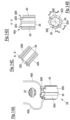
- FIGS. 14A to 14D show a further embodiment of the guide device 28, wherein Fig. 14A is a perspective view and the Fig. 14B to 14D
- insulating pins 40 instead of the insulating pins 40 of the embodiments according to the Figs. 8, 9 and 10A to 10D with a substantially circular cross-section, insulating pins 40 with an approximately trapezoidal cross-section are arranged in the slots 39 between adjacent segments 30A, 30B, 30C, 30D.
- the insulating pins 40 project radially outward beyond the segments 30A, 30B, 30C, 30D, so that they enable the guide device 28 to be supported in the housing 18A.
- the insulating pins 40 not only serve to electrically insulate the segments 30A, 30B, 30C, 30D from one another, but they also serve to radially support them.
- the elastic properties of the insulating pins 40 ensure - with suitable dimensioning of the radial projection - the desired preload on the segments 30A, 30B, 30C, 30D.
- the radial inner sides of the insulating pins 40 are set back from the inner sides of the segments 30A, 30B, 30C, 30D so as not to hinder the movement of the element 22 through the cavity 26.
- the insulating pins 40 can be separate components or can be molded onto the segments 30A, 30B, 30C, 30D. They are preferably made of an elastomer.
- the concept of creating a pre-tensioning device by means of elements with elastic properties that protrude radially outwards can in principle also be implemented separately from the insulating pins 40.
- elastic contact sections that project radially inwards can also be provided on the housing 18A - additionally or alternatively - and serve to radially support the guide device 28.
- the contact sections can be attached to the guide device 28 and/or the housing 18A or formed onto them or can be separate components.
- FIGS 15A to 15D show a further embodiment of the guide device 28, wherein Fig. 15A is a perspective view and the Fig. 15B to 15D Cross-sections or longitudinal sections.
- segments 30A, 30B, 30C, 30D segments 30A, 30B, 30C, 30C', 30C", 30D, 30D', 30D" are provided, between each of which an insulating pin 40 is arranged in a corresponding slot 39.
- Fig. 16 shows an embodiment of the guide device 28 in which the segment 30B (as in the embodiments described above) is directly connected to a conductor 46B. If an element 22 is introduced into the cavity 26, it presses the segments 30A, 30B apart against the prestress generated by the rings 42. As a result, a contact point 59A provided on the segment 30A comes into contact with a contact point 59B provided on the housing 18A. The housing 18A is in turn connected to the conductor 46A. In this case too, an electrical circuit is thus closed by the element 22, but a minimum relative movement of the segments 30A, 30B, which is determined by a distance between the contact points 59A, 59B in a basic state, 30B must be added to ultimately close the circuit.
- Fig. 17 shows a detection device in which the segment 30A has a plurality of detector elements 60 - for example contact surfaces - which are connected to each other in pairs. If the element 22 is in a position in which the two contact surfaces 60 of a connected pair are in contact with it, an electrical circuit is closed again, which enables the position of the element 22 in the cavity 26 to be determined. In Fig. 17 This situation is illustrated by the position of element 22, which short-circuits the two uppermost detector elements 60.
- the contact surfaces 60 can also be provided, which do not necessarily have to be functionally coupled to one another in pairs.
- sound sources and sound sensors can be provided which detect a reflection of sound waves on the element 22.
- the detector elements 60 can also be motion or vibration sensors in order to detect changes in the oscillation/vibration pattern or the natural oscillation of the guide device 28 or the base plate 18 (the elements 60 - or at least one element 60 - can then also be attached inside or outside to the housing 18A) which is caused by the presence/location/position of an element 22 in the cavity.
- the detector elements 60 can also be optical or magnetic sensors or pressure sensors or sensors of another type (e.g. embedded measuring coils).
- Fig. 18 shows a further embodiment of the guide device 28.
- detector elements 60 are provided on both the segment 30A and the segment 30B. These can, for example, be coupled to one another in such a way that opposing detector elements 60 form a pair that serves to generate a signal (eg contact surface pair or transmitter-receiver pair). It is also possible to control and/or monitor the individual elements 60 individually or in groups in order to obtain a more precise picture of the position of the element 22 and/or its location in space.
- a signal eg contact surface pair or transmitter-receiver pair
- a tilted element 22 was drawn which, due to its position, is in contact with two detector elements/contact surfaces 60 which are not opposite one another and thus closes an electrical circuit between these elements 60, which is detected by the control device and interpreted as a malfunction.
- Fig. 19 shows a plan view of a guide segment 30A with several detector elements 60, which are arranged not only in the axial direction (cf. setting direction S) but also in the circumferential direction.
- detector elements 60 can be selected as required (particularly with regard to the desired spatial resolution of the element detection).
- the type of detector elements used including electrical measurement - e.g. voltage, current, resistance -, measurement of acoustic signals, measurement of vibrations and/or movements and/or distances, measurement of optical signals, measurement of mechanical parameters - e.g. pressure and/or voltage) can also be freely selected. Different detector types can also be combined to create a detection device suitable for the respective application.
- Fig. 20 shows an embodiment of a detection device based on the measurement of a change in distance between the segments 30A, 30B.
- a connecting element 61 serving as a measuring device is provided, which bridges the slot 39 and connects the two segments 30A, 30B to one another.
- This can be, for example, an electrical conductor whose electrical properties are influenced by a change in length, or a strain gauge.
- distance sensors 62 eg capacitive sensors
- strain gauges or piezo sensors can also be provided.
- Fig. 22 shows a detection device based on the measurement of a pressure in the area of the guide device 28.
- compressed air is introduced into the cavity 26 (see arrow D).
- the resulting pressure is measured by means of corresponding pressure sensors 64. The pressure occurring at the one measuring point or the several measuring points depends, among other things, on whether and, if applicable, where an element 22 is located in the cavity 26.
Landscapes
- Engineering & Computer Science (AREA)
- Mechanical Engineering (AREA)
- Moulds For Moulding Plastics Or The Like (AREA)
- Automatic Assembly (AREA)
- Connection Of Plates (AREA)
- Details Of Spanners, Wrenches, And Screw Drivers And Accessories (AREA)
- Jigs For Machine Tools (AREA)
- Actuator (AREA)
- Transmission And Conversion Of Sensor Element Output (AREA)
Applications Claiming Priority (2)
| Application Number | Priority Date | Filing Date | Title |
|---|---|---|---|
| DE102018113868.7A DE102018113868A1 (de) | 2018-06-11 | 2018-06-11 | Setzeinrichtung |
| EP19178114.5A EP3581335B1 (fr) | 2018-06-11 | 2019-06-04 | Dispositif de positionnement |
Related Parent Applications (2)
| Application Number | Title | Priority Date | Filing Date |
|---|---|---|---|
| EP19178114.5A Division-Into EP3581335B1 (fr) | 2018-06-11 | 2019-06-04 | Dispositif de positionnement |
| EP19178114.5A Division EP3581335B1 (fr) | 2018-06-11 | 2019-06-04 | Dispositif de positionnement |
Publications (3)
| Publication Number | Publication Date |
|---|---|
| EP4374985A2 true EP4374985A2 (fr) | 2024-05-29 |
| EP4374985A3 EP4374985A3 (fr) | 2024-07-31 |
| EP4374985B1 EP4374985B1 (fr) | 2025-12-24 |
Family
ID=66751999
Family Applications (2)
| Application Number | Title | Priority Date | Filing Date |
|---|---|---|---|
| EP24169125.2A Active EP4374985B1 (fr) | 2018-06-11 | 2019-06-04 | Dispositif de pose |
| EP19178114.5A Active EP3581335B1 (fr) | 2018-06-11 | 2019-06-04 | Dispositif de positionnement |
Family Applications After (1)
| Application Number | Title | Priority Date | Filing Date |
|---|---|---|---|
| EP19178114.5A Active EP3581335B1 (fr) | 2018-06-11 | 2019-06-04 | Dispositif de positionnement |
Country Status (6)
| Country | Link |
|---|---|
| US (1) | US20190374998A1 (fr) |
| EP (2) | EP4374985B1 (fr) |
| CN (1) | CN110576308A (fr) |
| DE (1) | DE102018113868A1 (fr) |
| ES (2) | ES2981162T3 (fr) |
| PL (1) | PL3581335T3 (fr) |
Families Citing this family (1)
| Publication number | Priority date | Publication date | Assignee | Title |
|---|---|---|---|---|
| DE102024108289A1 (de) * | 2024-03-22 | 2025-09-25 | Tox Pressotechnik Gmbh & Co. Kg | Vorrichtung zum Anbringen eines Fügeelements und Verarbeitungssystem |
Citations (5)
| Publication number | Priority date | Publication date | Assignee | Title |
|---|---|---|---|---|
| US2845968A (en) | 1957-01-23 | 1958-08-05 | Anthony J Luber | Power driven screw driver having screw holding means |
| DE1728463A1 (de) | 1963-10-01 | 1973-02-15 | Clyde Corp | Automatischer schrauber |
| DE2415241A1 (de) | 1974-03-29 | 1975-10-16 | Herbert Fehlings | Einrichtung zum pneumatischen zufuehren von schrauben o.dgl. aus einem vereinzelner in das mundstueck eines schraubers o.dgl. |
| DE3236547A1 (de) | 1982-10-02 | 1984-04-05 | Herbert 6228 Eltville Fehlings | Auslauf eines mundstueckes von drehschraubern, schlagschraubern, niethaemmern udgl. |
| WO1994015736A1 (fr) | 1993-01-07 | 1994-07-21 | Henrob Ltd. | Outils de mise en place ameliores pour machines a riveter |
Family Cites Families (5)
| Publication number | Priority date | Publication date | Assignee | Title |
|---|---|---|---|---|
| DE925745C (de) * | 1951-12-16 | 1955-03-28 | Ernst Heinkel Motorenbau Ges M | Vorrichtung zum UEberwachen der Nietzufuhr fuer automatische Nietmaschinen |
| WO2001097999A2 (fr) * | 2000-06-17 | 2001-12-27 | Textron Inc. | Support de rivet |
| DE102008051488A1 (de) * | 2008-10-13 | 2010-04-15 | Böllhoff Verbindungstechnik GmbH | Kopfstück für ein Setzgerät |
| US20130263433A1 (en) * | 2012-03-26 | 2013-10-10 | Newfrey Llc | Automated Fastener Setting Tool |
| DE102013012222B4 (de) * | 2012-08-02 | 2020-12-03 | Richard Bergner Verbindungstechnik Gmbh & Co Kg | Vorrichtung sowie Verfahren zum reversiblen Greifen eines bolzenförmigen Elements, insbesondere eines Nietdorns |
-
2018
- 2018-06-11 DE DE102018113868.7A patent/DE102018113868A1/de not_active Withdrawn
-
2019
- 2019-06-04 PL PL19178114.5T patent/PL3581335T3/pl unknown
- 2019-06-04 EP EP24169125.2A patent/EP4374985B1/fr active Active
- 2019-06-04 ES ES19178114T patent/ES2981162T3/es active Active
- 2019-06-04 ES ES24169125T patent/ES3059642T3/es active Active
- 2019-06-04 EP EP19178114.5A patent/EP3581335B1/fr active Active
- 2019-06-10 US US16/436,248 patent/US20190374998A1/en not_active Abandoned
- 2019-06-11 CN CN201910500722.6A patent/CN110576308A/zh active Pending
Patent Citations (5)
| Publication number | Priority date | Publication date | Assignee | Title |
|---|---|---|---|---|
| US2845968A (en) | 1957-01-23 | 1958-08-05 | Anthony J Luber | Power driven screw driver having screw holding means |
| DE1728463A1 (de) | 1963-10-01 | 1973-02-15 | Clyde Corp | Automatischer schrauber |
| DE2415241A1 (de) | 1974-03-29 | 1975-10-16 | Herbert Fehlings | Einrichtung zum pneumatischen zufuehren von schrauben o.dgl. aus einem vereinzelner in das mundstueck eines schraubers o.dgl. |
| DE3236547A1 (de) | 1982-10-02 | 1984-04-05 | Herbert 6228 Eltville Fehlings | Auslauf eines mundstueckes von drehschraubern, schlagschraubern, niethaemmern udgl. |
| WO1994015736A1 (fr) | 1993-01-07 | 1994-07-21 | Henrob Ltd. | Outils de mise en place ameliores pour machines a riveter |
Also Published As
| Publication number | Publication date |
|---|---|
| EP3581335B1 (fr) | 2024-05-29 |
| EP4374985B1 (fr) | 2025-12-24 |
| PL3581335T3 (pl) | 2024-12-09 |
| US20190374998A1 (en) | 2019-12-12 |
| ES2981162T3 (es) | 2024-10-07 |
| EP3581335A1 (fr) | 2019-12-18 |
| DE102018113868A1 (de) | 2019-12-12 |
| CN110576308A (zh) | 2019-12-17 |
| EP4374985A3 (fr) | 2024-07-31 |
| ES3059642T3 (en) | 2026-03-23 |
Similar Documents
| Publication | Publication Date | Title |
|---|---|---|
| DE19910124B4 (de) | Auswurfstift mit Drucksensor | |
| EP2210115B1 (fr) | Cassette à grille pleine surface pour un testeur parallèle servant à tester un circuit imprimé nu, pointe de contact à ressort pour une telle cassette à grille pleine surface et adaptateur pour un testeur parallèle servant à tester un circuit imprimé nu | |
| DE102007020882B4 (de) | Einrichtung zur Überprüfung der Befestigung einer Leiterbahnplatte an einem Träger | |
| EP0182013A2 (fr) | Dispositif pour la fixation d'un premier élément de construction | |
| DE3829846C2 (de) | Einzugkraft-Meßgerät für Werkzeug-Spannvorrichtungen | |
| DE102005022340B4 (de) | Klopfsensor und Verfahren zu dessen Herstellung | |
| EP3581336B1 (fr) | Dispositif de positionnement | |
| EP3581335B1 (fr) | Dispositif de positionnement | |
| EP1600781B1 (fr) | Dispositif pour le test électrique d'un dispositif à tester | |
| DE102015211603B4 (de) | Linearantrieb mit Positionserfassungseinrichtung | |
| DE3407620C2 (fr) | ||
| EP3802219B1 (fr) | Module d'avertisseur sonore pour volant de véhicule et ensemble comprenant un module de sac gonflable de conducteur et un module avertisseur sonore | |
| EP3946994B1 (fr) | Procédé pour l'établissement d'une connexion compensée en tolérance entre un premier composant et un deuxième composant et entraînement électrique | |
| EP1162694B1 (fr) | Appareil pour la connexion de conducteurs électriques | |
| DE2732761C3 (de) | Experimentiertafel zum Aufbau elektrischer Schaltungen | |
| EP1496283A1 (fr) | Dispositif de détéction d'usure pour garniture de frein. | |
| DE102022121173A1 (de) | Setzeinrichtung | |
| DE2056391C3 (de) | Strickmaschine, insbesondere Flachstrickmaschine, mit einer Sicherungseinrichtung | |
| DE102018115073A1 (de) | VERFAHREN UND SPRITZGIEßMASCHINE ZUM HERSTELLEN EINES DRUCKAUSGLEICHSVENTILS FÜR EIN GEHÄUSEBAUTEIL | |
| DE102016124485A1 (de) | Bedienvorrichtung mit einer ersten und einer zweiten kapazitiven Messeinheit, Kraftfahrzeug, sowie Verfahren zum Betreiben einer Bedienvorrichtung | |
| DE102006040022B4 (de) | Gassackmodul | |
| EP4204699A1 (fr) | Élément de palier doté d'un capteur et d'un dispositif de télémétrie | |
| DE102021109290A1 (de) | Werkzeug zur Herstellung einer Anordnung, Verfahren zur Herstellung der Anordnung mit dem Werkzeug und Anordnung | |
| DE102023103428A1 (de) | Elektromechanisches Wandlerelement | |
| DE19705383A1 (de) | Stoßsensor und Verfahren für dessen Herstellung |
Legal Events
| Date | Code | Title | Description |
|---|---|---|---|
| PUAI | Public reference made under article 153(3) epc to a published international application that has entered the european phase |
Free format text: ORIGINAL CODE: 0009012 |
|
| STAA | Information on the status of an ep patent application or granted ep patent |
Free format text: STATUS: THE APPLICATION HAS BEEN PUBLISHED |
|
| AC | Divisional application: reference to earlier application |
Ref document number: 3581335 Country of ref document: EP Kind code of ref document: P |
|
| AK | Designated contracting states |
Kind code of ref document: A2 Designated state(s): AL AT BE BG CH CY CZ DE DK EE ES FI FR GB GR HR HU IE IS IT LI LT LU LV MC MK MT NL NO PL PT RO RS SE SI SK SM TR |
|
| REG | Reference to a national code |
Ref country code: DE Ref legal event code: R079 Free format text: PREVIOUS MAIN CLASS: B21J0015020000 Ipc: B25B0023100000 Ref document number: 502019014229 Country of ref document: DE |
|
| PUAL | Search report despatched |
Free format text: ORIGINAL CODE: 0009013 |
|
| AK | Designated contracting states |
Kind code of ref document: A3 Designated state(s): AL AT BE BG CH CY CZ DE DK EE ES FI FR GB GR HR HU IE IS IT LI LT LU LV MC MK MT NL NO PL PT RO RS SE SI SK SM TR |
|
| RIC1 | Information provided on ipc code assigned before grant |
Ipc: B21J 15/28 20060101ALI20240624BHEP Ipc: B21J 15/02 20060101ALI20240624BHEP Ipc: B25B 23/10 20060101AFI20240624BHEP |
|
| STAA | Information on the status of an ep patent application or granted ep patent |
Free format text: STATUS: REQUEST FOR EXAMINATION WAS MADE |
|
| 17P | Request for examination filed |
Effective date: 20240820 |
|
| RBV | Designated contracting states (corrected) |
Designated state(s): AL AT BE BG CH CY CZ DE DK EE ES FI FR GB GR HR HU IE IS IT LI LT LU LV MC MK MT NL NO PL PT RO RS SE SI SK SM TR |
|
| GRAP | Despatch of communication of intention to grant a patent |
Free format text: ORIGINAL CODE: EPIDOSNIGR1 |
|
| STAA | Information on the status of an ep patent application or granted ep patent |
Free format text: STATUS: GRANT OF PATENT IS INTENDED |
|
| RIC1 | Information provided on ipc code assigned before grant |
Ipc: B25B 23/10 20060101AFI20250627BHEP Ipc: B21J 15/02 20060101ALI20250627BHEP Ipc: B21J 15/28 20060101ALI20250627BHEP |
|
| INTG | Intention to grant announced |
Effective date: 20250718 |
|
| GRAS | Grant fee paid |
Free format text: ORIGINAL CODE: EPIDOSNIGR3 |
|
| GRAA | (expected) grant |
Free format text: ORIGINAL CODE: 0009210 |
|
| STAA | Information on the status of an ep patent application or granted ep patent |
Free format text: STATUS: THE PATENT HAS BEEN GRANTED |
|
| AC | Divisional application: reference to earlier application |
Ref document number: 3581335 Country of ref document: EP Kind code of ref document: P |
|
| AK | Designated contracting states |
Kind code of ref document: B1 Designated state(s): AL AT BE BG CH CY CZ DE DK EE ES FI FR GB GR HR HU IE IS IT LI LT LU LV MC MK MT NL NO PL PT RO RS SE SI SK SM TR |
|
| REG | Reference to a national code |
Ref country code: CH Ref legal event code: F10 Free format text: ST27 STATUS EVENT CODE: U-0-0-F10-F00 (AS PROVIDED BY THE NATIONAL OFFICE) Effective date: 20251224 Ref country code: GB Ref legal event code: FG4D Free format text: NOT ENGLISH |
|
| REG | Reference to a national code |
Ref country code: DE Ref legal event code: R096 Ref document number: 502019014229 Country of ref document: DE |
|
| REG | Reference to a national code |
Ref country code: ES Ref legal event code: FG2A Ref document number: 3059642 Country of ref document: ES Kind code of ref document: T3 Effective date: 20260323 |
|
| REG | Reference to a national code |
Ref country code: LT Ref legal event code: MG9D |
|
| PG25 | Lapsed in a contracting state [announced via postgrant information from national office to epo] |
Ref country code: NO Free format text: LAPSE BECAUSE OF FAILURE TO SUBMIT A TRANSLATION OF THE DESCRIPTION OR TO PAY THE FEE WITHIN THE PRESCRIBED TIME-LIMIT Effective date: 20260324 |
|
| PG25 | Lapsed in a contracting state [announced via postgrant information from national office to epo] |
Ref country code: FI Free format text: LAPSE BECAUSE OF FAILURE TO SUBMIT A TRANSLATION OF THE DESCRIPTION OR TO PAY THE FEE WITHIN THE PRESCRIBED TIME-LIMIT Effective date: 20251224 Ref country code: HR Free format text: LAPSE BECAUSE OF FAILURE TO SUBMIT A TRANSLATION OF THE DESCRIPTION OR TO PAY THE FEE WITHIN THE PRESCRIBED TIME-LIMIT Effective date: 20251224 |
|
| PG25 | Lapsed in a contracting state [announced via postgrant information from national office to epo] |
Ref country code: RS Free format text: LAPSE BECAUSE OF FAILURE TO SUBMIT A TRANSLATION OF THE DESCRIPTION OR TO PAY THE FEE WITHIN THE PRESCRIBED TIME-LIMIT Effective date: 20260324 |
|
| PG25 | Lapsed in a contracting state [announced via postgrant information from national office to epo] |
Ref country code: LV Free format text: LAPSE BECAUSE OF FAILURE TO SUBMIT A TRANSLATION OF THE DESCRIPTION OR TO PAY THE FEE WITHIN THE PRESCRIBED TIME-LIMIT Effective date: 20251224 |