EP4375014A2 - Entraînement à vis - Google Patents
Entraînement à vis Download PDFInfo
- Publication number
- EP4375014A2 EP4375014A2 EP24169843.0A EP24169843A EP4375014A2 EP 4375014 A2 EP4375014 A2 EP 4375014A2 EP 24169843 A EP24169843 A EP 24169843A EP 4375014 A2 EP4375014 A2 EP 4375014A2
- Authority
- EP
- European Patent Office
- Prior art keywords
- screw head
- screw
- geometry
- section
- bushing
- Prior art date
- Legal status (The legal status is an assumption and is not a legal conclusion. Google has not performed a legal analysis and makes no representation as to the accuracy of the status listed.)
- Pending
Links
Images


Classifications
-
- F—MECHANICAL ENGINEERING; LIGHTING; HEATING; WEAPONS; BLASTING
- F16—ENGINEERING ELEMENTS AND UNITS; GENERAL MEASURES FOR PRODUCING AND MAINTAINING EFFECTIVE FUNCTIONING OF MACHINES OR INSTALLATIONS; THERMAL INSULATION IN GENERAL
- F16B—DEVICES FOR FASTENING OR SECURING CONSTRUCTIONAL ELEMENTS OR MACHINE PARTS TOGETHER, e.g. NAILS, BOLTS, CIRCLIPS, CLAMPS, CLIPS OR WEDGES; JOINTS OR JOINTING
- F16B23/00—Specially shaped nuts or heads of bolts or screws for rotations by a tool
- F16B23/0007—Specially shaped nuts or heads of bolts or screws for rotations by a tool characterised by the shape of the recess or the protrusion engaging the tool
- F16B23/0015—Specially shaped nuts or heads of bolts or screws for rotations by a tool characterised by the shape of the recess or the protrusion engaging the tool substantially rectangular, e.g. one-slot head
-
- F—MECHANICAL ENGINEERING; LIGHTING; HEATING; WEAPONS; BLASTING
- F16—ENGINEERING ELEMENTS AND UNITS; GENERAL MEASURES FOR PRODUCING AND MAINTAINING EFFECTIVE FUNCTIONING OF MACHINES OR INSTALLATIONS; THERMAL INSULATION IN GENERAL
- F16B—DEVICES FOR FASTENING OR SECURING CONSTRUCTIONAL ELEMENTS OR MACHINE PARTS TOGETHER, e.g. NAILS, BOLTS, CIRCLIPS, CLAMPS, CLIPS OR WEDGES; JOINTS OR JOINTING
- F16B5/00—Joining sheets or plates, e.g. panels, to one another or to strips or bars parallel to them
- F16B5/02—Joining sheets or plates, e.g. panels, to one another or to strips or bars parallel to them by means of fastening members using screw-thread
- F16B5/0275—Joining sheets or plates, e.g. panels, to one another or to strips or bars parallel to them by means of fastening members using screw-thread the screw-threaded element having at least two axially separated threaded portions
-
- F—MECHANICAL ENGINEERING; LIGHTING; HEATING; WEAPONS; BLASTING
- F16—ENGINEERING ELEMENTS AND UNITS; GENERAL MEASURES FOR PRODUCING AND MAINTAINING EFFECTIVE FUNCTIONING OF MACHINES OR INSTALLATIONS; THERMAL INSULATION IN GENERAL
- F16B—DEVICES FOR FASTENING OR SECURING CONSTRUCTIONAL ELEMENTS OR MACHINE PARTS TOGETHER, e.g. NAILS, BOLTS, CIRCLIPS, CLAMPS, CLIPS OR WEDGES; JOINTS OR JOINTING
- F16B23/00—Specially shaped nuts or heads of bolts or screws for rotations by a tool
- F16B23/0007—Specially shaped nuts or heads of bolts or screws for rotations by a tool characterised by the shape of the recess or the protrusion engaging the tool
-
- A—HUMAN NECESSITIES
- A61—MEDICAL OR VETERINARY SCIENCE; HYGIENE
- A61C—DENTISTRY; APPARATUS OR METHODS FOR ORAL OR DENTAL HYGIENE
- A61C8/00—Means to be fixed to the jaw-bone for consolidating natural teeth or for fixing dental prostheses thereon; Dental implants; Implanting tools
- A61C8/0089—Implanting tools or instruments
-
- B—PERFORMING OPERATIONS; TRANSPORTING
- B25—HAND TOOLS; PORTABLE POWER-DRIVEN TOOLS; MANIPULATORS
- B25B—TOOLS OR BENCH DEVICES NOT OTHERWISE PROVIDED FOR, FOR FASTENING, CONNECTING, DISENGAGING, OR HOLDING
- B25B15/00—Screwdrivers
- B25B15/001—Screwdrivers characterised by material or shape of the tool bit
- B25B15/004—Screwdrivers characterised by material or shape of the tool bit characterised by cross-section
- B25B15/005—Screwdrivers characterised by material or shape of the tool bit characterised by cross-section with cross- or star-shaped cross-section
-
- F—MECHANICAL ENGINEERING; LIGHTING; HEATING; WEAPONS; BLASTING
- F16—ENGINEERING ELEMENTS AND UNITS; GENERAL MEASURES FOR PRODUCING AND MAINTAINING EFFECTIVE FUNCTIONING OF MACHINES OR INSTALLATIONS; THERMAL INSULATION IN GENERAL
- F16B—DEVICES FOR FASTENING OR SECURING CONSTRUCTIONAL ELEMENTS OR MACHINE PARTS TOGETHER, e.g. NAILS, BOLTS, CIRCLIPS, CLAMPS, CLIPS OR WEDGES; JOINTS OR JOINTING
- F16B23/00—Specially shaped nuts or heads of bolts or screws for rotations by a tool
- F16B23/0007—Specially shaped nuts or heads of bolts or screws for rotations by a tool characterised by the shape of the recess or the protrusion engaging the tool
- F16B23/003—Specially shaped nuts or heads of bolts or screws for rotations by a tool characterised by the shape of the recess or the protrusion engaging the tool star-shaped or multi-lobular, e.g. Torx-type, twelve-point star
-
- F—MECHANICAL ENGINEERING; LIGHTING; HEATING; WEAPONS; BLASTING
- F16—ENGINEERING ELEMENTS AND UNITS; GENERAL MEASURES FOR PRODUCING AND MAINTAINING EFFECTIVE FUNCTIONING OF MACHINES OR INSTALLATIONS; THERMAL INSULATION IN GENERAL
- F16B—DEVICES FOR FASTENING OR SECURING CONSTRUCTIONAL ELEMENTS OR MACHINE PARTS TOGETHER, e.g. NAILS, BOLTS, CIRCLIPS, CLAMPS, CLIPS OR WEDGES; JOINTS OR JOINTING
- F16B23/00—Specially shaped nuts or heads of bolts or screws for rotations by a tool
- F16B23/0053—Specially shaped nuts or heads of bolts or screws for rotations by a tool with a conical or prismatic recess for receiving a centering pin of the tool apparatus
-
- F—MECHANICAL ENGINEERING; LIGHTING; HEATING; WEAPONS; BLASTING
- F16—ENGINEERING ELEMENTS AND UNITS; GENERAL MEASURES FOR PRODUCING AND MAINTAINING EFFECTIVE FUNCTIONING OF MACHINES OR INSTALLATIONS; THERMAL INSULATION IN GENERAL
- F16B—DEVICES FOR FASTENING OR SECURING CONSTRUCTIONAL ELEMENTS OR MACHINE PARTS TOGETHER, e.g. NAILS, BOLTS, CIRCLIPS, CLAMPS, CLIPS OR WEDGES; JOINTS OR JOINTING
- F16B7/00—Connections of rods or tubes, e.g. of non-circular section, mutually, including resilient connections
- F16B7/18—Connections of rods or tubes, e.g. of non-circular section, mutually, including resilient connections using screw-thread elements
- F16B7/185—Connections of rods or tubes, e.g. of non-circular section, mutually, including resilient connections using screw-thread elements with a node element
-
- F—MECHANICAL ENGINEERING; LIGHTING; HEATING; WEAPONS; BLASTING
- F16—ENGINEERING ELEMENTS AND UNITS; GENERAL MEASURES FOR PRODUCING AND MAINTAINING EFFECTIVE FUNCTIONING OF MACHINES OR INSTALLATIONS; THERMAL INSULATION IN GENERAL
- F16B—DEVICES FOR FASTENING OR SECURING CONSTRUCTIONAL ELEMENTS OR MACHINE PARTS TOGETHER, e.g. NAILS, BOLTS, CIRCLIPS, CLAMPS, CLIPS OR WEDGES; JOINTS OR JOINTING
- F16B23/00—Specially shaped nuts or heads of bolts or screws for rotations by a tool
- F16B23/0007—Specially shaped nuts or heads of bolts or screws for rotations by a tool characterised by the shape of the recess or the protrusion engaging the tool
- F16B23/0023—Specially shaped nuts or heads of bolts or screws for rotations by a tool characterised by the shape of the recess or the protrusion engaging the tool substantially cross-shaped
Definitions
- the invention relates to a screw head bushing for a screw according to the preamble of claim 1, a screw head drive according to the preamble of claim 4, a forming tool for forming a screw head bushing according to the preamble of claim 7, a screw according to the preamble of claim 10, and a kit comprising a screw and a screw head drive.
- Screw head bushings are geometric structures that are formed in screw heads and serve to accommodate a screw head drive in a rotationally fixed manner.
- the screw head drive can be used to transfer torque to the screw in order to screw the screw into a material or to unscrew it from it.
- a number of geometries for screw head drives and screw head bushings are known in the state of the art, such as Phillips, slotted, or Torx geometries. These geometries are often referred to as screw drives.
- Geometries such as the Torx geometry are optimized to transfer high torques from the screw head drive to the screw head bushing.
- a disadvantage of many screw drives is that if the screw head drive is not centered correctly or is aligned at an angle to the screw head bushing, there is insufficient positive engagement between the screw head drive and the screw head bushing, which can cause the screw head drive to slip in the screw head bushing. This can damage the screw head bushing and/or the screw head drive, meaning that the torque required to screw in or unscrew a screw fitted with the screw head drive can no longer be transmitted. This means that the screw in question can no longer be screwed in or removed from a material using simple means, which could damage a workpiece into which the screw has been screwed, or impair its function.
- TTAP screw drive A geometry for improved alignment of a screw head drive in a screw head socket is known in the art as TTAP screw drive, and under the US6,951,158 B1 published.
- the screw head bushing of the TTAP screw drive comprises an outer and an inner section, with the inner section comprising a centering cone. This aligns the screw head drive centrally in the screw head bushing.
- the present invention is based on the object of providing an alternative geometry for screw drives, which ensures a high torque transmission, and additionally provides for centering of the screw head drive in the screw head bushing.
- this object is achieved by a screw head bushing with the features of claim 1, a screw head drive with the features of claim 4, a forming tool for forming a screw head bushing with the features of claim 7, a screw with the features of claim 11 and a kit comprising a screw and a screw head drive with the features of claim 14.
- the inventive design of the screw head bushing for a screw comprises an outer section and an inner section following the outer section.
- the outer section has a larger diameter than the inner section in at least one first axis oriented perpendicular to a depth of the screw head bushing and is essentially designed as a truncated cone tapering towards the inner section.
- the inner section is designed as an engagement geometry for the rotationally fixed reception of a screw head drive.
- the conically tapered outer section provides a guide for a screw head drive, which prevents the screw head drive from being inserted obliquely into the screw head bushing.
- the inner section designed as an engagement geometry lies behind or at a greater depth than the outer section, which ensures that the screw head drive is centered by the outer section before it engages in the engagement geometry. This prevents the engagement geometry from wearing out due to improperly inserted screw head drives.
- the outer section comprises a truncated cone that is inclined relative to a cylinder surface in the range of 2.5° to 10°. This has the advantage that a screw head drive that is attached at an angle can be centered without great effort.
- the screw head bushing according to the invention comprises an insertion area with insertion surfaces arranged between the outer section and the inner section, wherein the insertion surfaces have an inclination of substantially 10° with respect to a base surface of the truncated cone of the outer section. This facilitates the sliding of an engagement geometry of the screw head drive into the engagement geometry of the screw head bushing.
- the engagement geometry of a screw head bushing can be a Phillips geometry, a Torx geometry or a slot geometry.
- the engagement geometry is a the screw head bushing in a slot geometry oriented normal to the depth of the screw head bushing, a second axis different from the first axis.
- the inventive design of the screw head drive comprises an outer section and an inner section following the outer section, wherein the inner section has a larger diameter than the outer section in at least one first axis oriented perpendicular to a height of the screw head drive.
- the inner section is essentially designed as a truncated cone tapering in the direction of the outer section, and the outer section comprises an engagement geometry which is designed to engage in an engagement geometry of a screw head bushing in a rotationally fixed manner.
- the conically tapered inner section of the screw head drive provides a guide, which prevents the engagement geometry of the screw head drive from being introduced obliquely into an engagement geometry of a screw head bushing.
- the inner section of the screw head drive according to the invention comprises a truncated cone that is inclined relative to a cylinder jacket in the range of 2.5° to 10°. This provides the advantage that a screw head drive that is placed at an angle can be centered without great effort.
- the screw head drive according to the invention comprises an insertion area with insertion surfaces arranged between the outer section and the inner section, wherein the insertion surfaces have an inclination of substantially 10° with respect to a base surface of the truncated cone of the inner section. This facilitates the sliding of the engagement geometry of the screw head drive into the engagement geometry of the screw head bushing.
- the attack geometry of a screw head drive can be a Phillips geometry, a Torx geometry or a slot geometry.
- the attack geometry is a slot geometry that runs through the screw head drive in a second axis that is oriented normal to the height of the screw head drive and different from the first axis.
- the forming tool according to the invention for forming a screw head bushing in a screw head comprises an outer section and an inner section following the outer section, wherein the inner section has a larger diameter than the outer section in at least one first axis oriented perpendicular to a height of the forming tool.
- the inner section is essentially designed as a truncated cone tapering in the direction of the outer section, and the outer Section comprises an engagement geometry which is designed to form an engagement geometry in the screw head for the rotationally fixed reception of a screw head drive.
- the inner section of the forming tool according to the invention preferably comprises a truncated cone that is inclined relative to a cylinder jacket in the range of 2.5° to 10°.
- this also comprises an insertion area with insertion surfaces arranged between the outer section and the inner section, wherein the insertion surfaces have an inclination of essentially 10° relative to a base surface of the truncated cone of the inner section. This enables a screw head drive to be easily inserted and centered in a screw head bushing.
- the attack geometry of a forming tool can be a Phillips geometry, a Torx geometry or a slot geometry.
- the attack geometry is a slot geometry that runs through the forming tool in a second axis that is oriented normal to the height of the forming tool and is different from the first axis.
- the screw according to the invention comprises a screw head bushing according to the invention, which was preferably formed with a forming tool according to the invention.
- Figure 1a shows a screw head of a screw 1 in cross section, to show a screw head bushing 2 according to the invention provided in the screw 1.
- the screw head bushing 2 has an outer section 3 and an inner section 4, which follows the outer section 3.
- the outer section 3 begins at a cover surface 5 of the screw head, wherein for screwing in the screw 1 a screw head drive 6, which is inserted into the Figures 4a to 4c shown, is introduced through the outer section 3 into the inner section 4.
- the outer section 3 has in at least one normal to a depth T of the screw head bushing 2, in Figure 1c visible first axis A 1 has a larger diameter D than the inner section 4.
- the outer section 3 essentially has the shape of a truncated cone tapering towards the inner section 4. This provides a guide for the screw head drive 6.
- the inner section 4 is designed as an engagement geometry for the rotationally fixed reception of the screw head drive 6.
- the engagement geometry can be a geometry known from the prior art for screw drives. In particular, a Phillips geometry, a Torx geometry or a slot geometry is suitable as the engagement geometry. In the Figures 1 to 1c a Torx geometry is shown.
- FIG. 1b shows the screw head of screw 1 with the screw head bushing 2 according to Figure 1a in another cross-sectional view, which is compared Figure 1a rotated around a longitudinal axis L of the screw head drive 2.
- the Figures 1a to 1c The engagement geometry shown is a Torx geometry, where in Figure 1a a maximum diameter of the Torx geometry is visible.
- Figure 1c shows the screw head according to Figure 1a and 1b from above, with the engagement geometry visible in plan view.
- the outer section 3 of the screw head bushing according to the invention preferably has a truncated cone that is inclined relative to a cylinder jacket in the range of 2.5° to 10°.
- the inclination of the truncated cone is in the Figures 1a and 1b marked with the angle ⁇ . This angle range has proven to be particularly advantageous with regard to easy insertion of the screw head drive 6.
- the screw head bushing 2 according to the invention also comprises an insertion area 7 with insertion surfaces 8 arranged between the outer section 3 and the inner section 4.
- insertion surfaces 8 have, according to the preferred embodiment of the screw head bushing 2 according to the invention, a Figure 1a shown inclination ⁇ of essentially 10° with respect to a base surface of the truncated cone of the outer section 3. This facilitates the sliding of an attack geometry of the screw head drive 6 into the engagement geometry of the screw head bushing 2.
- FIGS. 2a, 2b and 2c show an alternative design variant of a screw head bushing 2 with an engagement geometry in the form of a Phillips geometry
- FIG. 3a, 3b, and 3c show the screw head bushing 2 according to the invention with an engagement geometry in the form of a slot geometry.
- the engagement geometry is a slot geometry that runs through the screw head bushing 2 in a second axis A 2 that is oriented perpendicularly to the depth T of the screw head bushing 2 and different from the first axis A 1.
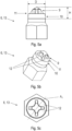
- FIG. 4a, 4b and 4c An example screw head drive 6 is shown in the Figures 4a, 4b and 4c
- the screw head drive 6 has an outer section 9 and an inner section 10 following the outer section 9, wherein the inner section 10 is in at least one, in Figure 4c visible, normal to a height H of the screw head drive 6 , has a larger diameter D than the outer section 9.
- the inner section 10 is essentially designed as a truncated cone tapering towards the outer section 9.
- the outer section 9 comprises an engagement geometry which is designed to engage in the engagement geometry of the screw head bushing 2 in a rotationally fixed manner. Any geometry known from the prior art for screw drives can be provided as the engagement geometry. This is shown in the Figures 4b and 4c in detail. In the Figures 4a to 4c a Torx geometry is shown.
- a Phillips geometry, a Torx geometry or a slot geometry can be selected as the attack geometry.
- the screw head drive 6 and the screw head bushing 2 essentially represent geometric shapes that complement each other.
- the conically tapered inner section 10 of the screw head drive 6, in conjunction with the conical design of the outer section 3 of the screw head bushing 2, provides a guide, which prevents the attack geometry of the screw head drive 6 from being inserted obliquely into an engagement geometry of the screw head bushing 2. This prevents improper insertion of the screw head drive 6 into the screw head bushing 2 and prevents the screw head drive 6 from spinning in the screw head bushing 2.
- the inner section 10 of the screw head drive 6 comprises a truncated cone inclined relative to a cylinder jacket in the range of 2.5° to 10°. This inclination is in Figure 4a with the inclination angle ⁇ . This angle range has proven to be particularly advantageous with regard to easy insertion of the screw head drive 6.
- the screw head drive 6 comprises an insertion area 11 arranged between the outer section 9 and the inner section 10 with Insertion surfaces 12.
- Insertion surfaces 12 are in Figure 4b and Figure 4c
- the insertion surfaces 12 preferably have a Figure 4b apparent inclination ⁇ of essentially 10° with respect to a base surface of the truncated cone of the inner section 10. This facilitates the sliding of the engagement geometry of the screw head drive 6 into the engagement geometry of the screw head bushing 2.
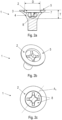
- FIGS. 5a, 5b and 5c show an exemplary screw head drive 6 with an attack geometry in the form of a Philipps geometry
- FIG. 6a, 6b and 6c show the screw head drive 6 according to the invention with an attack geometry in the form of a slot geometry.
- the attack geometry according to the invention is a slot geometry that runs through the screw head drive 6 in a second axis A 2 that is oriented normal to the height H of the screw head drive 6 and different from the first axis A 1 .
- a forming tool 13 according to the invention for forming a screw head bushing 2 in a screw head is used in screw production in order to form the screw head bushing 2 according to the invention in a screw head of a screw blank.
- This forming tool 13 has essentially the same geometry as the screw head drive 6 according to the invention.
- the forming tool 13 and the screw head bushing 2 thus represent essentially complementary geometric shapes to one another.
- the Figures 4a, 4b and 4c , 5a, 5b and 5c , as well as 6a, 6b and 6c thus also show an example of an upper section of a forming tool 13.
- the forming tool 13 for forming the screw head bushing 2 in a screw head comprises, like the screw head drive 6, an outer section 9 and an inner section 10 following the outer section 9, wherein the inner section 10 has a larger diameter D than the outer section 9 in at least one first axis A 1 oriented normal to a height H of the forming tool 13.
- the inner section 10 is essentially designed as a truncated cone tapering in the direction of the outer section 9, and the outer section 9 comprises an engagement geometry which is designed to form an engagement geometry in the screw head for the rotationally fixed reception of the screw head drive 6. Any geometry known from the prior art for screw drives can be provided as the engagement geometry or engagement geometry.
- the inner section 10 of the molding tool 13 according to the invention preferably comprises a truncated cone inclined relative to a cylinder surface in the range of 2.5° to 10°. This inclination is in Figure 4a with the inclination angle ⁇ . This angle range has proven to be particularly advantageous with regard to easy insertion of the screw head drive 6.
- the molding tool 13 comprises an insertion area 11 with insertion surfaces 12 arranged between the outer section 9 and the inner section 10.
- the insertion surfaces 12 preferably have a Figure 4b apparent inclination ⁇ of essentially 10° with respect to a base surface of the truncated cone of the inner section 10. This facilitates the sliding of the engagement geometry of the screw head drive 6 into the engagement geometry of the screw head bushing 2.
- FIGS. 5a, 5b and 5c show an exemplary forming tool 13 with an attack geometry in the form of a Philipps geometry
- FIG. 6a, 6b and 6c show a forming tool 13 according to the invention with an attack geometry in the form of a slot geometry.
- the attack geometry is clearly a slot geometry that runs through the forming tool 13 according to the invention in a second axis A 2 that is oriented normal to the height H of the screw head drive 6 and different from the first axis A 1 .
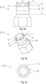
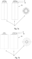
- the Figures 7a to 9b show an exemplary forming tool 13 in substantially complete representations, wherein the forming tool 13 comprises a section 14 for fastening the forming tool 13 in a screw production device.
- the Figures 7a and 7b show the exemplary forming tool 13 with an attack geometry in the form of a Torx geometry, in two different sizes.
- the Figures 8a and 8b show an exemplary forming tool 13 with an attack geometry in the form of a Phillips geometry, in two different sizes
- the Figures 9a and 9b show the forming tool 13 according to the invention with an attack geometry in the form of a slot geometry in two different sizes.
- a kit according to the invention comprises a screw 1 according to the invention and a screw head drive 6 according to the invention.
- the inner section 10 of the screw head drive 6 of the kit according to the invention has a truncated cone with a greater inclination angle ⁇ than a cylinder jacket than a truncated cone of the outer section 3 of the screw head bushing 2 of the screw 1 according to the invention.
- This inventive effect can be used on any type of screw drive geometry.
- a further advantage is the clean guidance in the axial direction of the screw head drive 6. This makes it impossible for the screw head drive 6 to be placed at an angle or at an angle on the screw 1, which minimizes or even completely prevents undesirable rubbing of the screw head bushing 2 and/or excessive wear of the screw head drive 6.
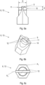
- Figure 10a and Figure 10b show an example screw 1.
- Figure 10a shows the exemplary screw 1 in a top view
- Figure 10b shows a sectional view of the exemplary screw from Figure 10a along the line AA.
- the screw 1 has a projection 15 which runs essentially annularly around the outer section 3 of the screw head bushing 2 and essentially in the longitudinal axis direction of the screw 1.
- the projection 15 preferably has a height of 0.75 mm.
- the projection 15 offers the advantage that it provides an additional depth T of the screw head bushing 2, whereby the outer section 3 can run at least partially within the projection 15. This makes it possible to increase the depth of the inner section 4, whereby a larger, force-transmitting contact surface is achieved between the engagement geometry of the screw head bushing 2 and the attack geometry of the screw head drive 6.
- Figure 11a and Figure 11b show another exemplary screw 1, in which the screw 1 has a, the outer portion 3 of the screw head bushing 2 essentially has a ring-shaped cover surface 16 which slopes outwards in the radial direction of the screw 2.
- the cover surface 16 preferably slopes over a height of 0.75 mm.
- Figure 11a shows the screw 1 in a top view and Figure 11b shows a sectional view of the screw from Figure 11a along the line AA.
- the shape of the cover surface 16 also achieves the technical effect of providing an additional depth T of the screw head bushing 2.
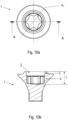
- Figure 12a and Figure 12b show another example screw 1.
- Figure 12a shows the screw 1 in a top view
- Figure 12b shows a sectional view of the screw from Figure 12a along the line AA.
- the screw 1 has an outer surface 17 which runs in the longitudinal axis direction of the screw 1 and essentially completely surrounds the outer section 3 of the screw head bushing 2.
- the outer surface 17 preferably has a height of 1.31 mm.
- the outer surface 17 also provides an additional depth T of the screw head bushing 2, as well as additional mechanical stability of the outer section 3.
- a TX25 drive known from the state of the art has a depth T of the screw head socket in the range of 1.9mm - 2.3mm. These depths T are usually achieved with a diameter of the screw head socket in the range of 5mm and with a head diameter of 9.5mm - 10mm. The height of the screw head is 4.8mm - 5.2mm.
- the screw 1 according to the invention has a screw head height in the range of 5.75 mm according to a defined screw size, the depth of the engagement geometry of the inner section 4 preferably being approximately 1.95 mm.
- the head diameter of the screw 1 is approximately 10 mm. For other screw sizes, these values are scaled accordingly.
Landscapes
- Engineering & Computer Science (AREA)
- General Engineering & Computer Science (AREA)
- Mechanical Engineering (AREA)
- Health & Medical Sciences (AREA)
- General Health & Medical Sciences (AREA)
- Orthopedic Medicine & Surgery (AREA)
- Dentistry (AREA)
- Epidemiology (AREA)
- Life Sciences & Earth Sciences (AREA)
- Animal Behavior & Ethology (AREA)
- Oral & Maxillofacial Surgery (AREA)
- Public Health (AREA)
- Veterinary Medicine (AREA)
- Injection Moulding Of Plastics Or The Like (AREA)
- Transmission Devices (AREA)
- Extrusion Moulding Of Plastics Or The Like (AREA)
- Details Of Spanners, Wrenches, And Screw Drivers And Accessories (AREA)
- Portable Nailing Machines And Staplers (AREA)
- Golf Clubs (AREA)
- Chair Legs, Seat Parts, And Backrests (AREA)
- Supporting Of Heads In Record-Carrier Devices (AREA)
- Moving Of Heads (AREA)
Applications Claiming Priority (3)
| Application Number | Priority Date | Filing Date | Title |
|---|---|---|---|
| ATGM50246/2019U AT17033U1 (de) | 2019-12-20 | 2019-12-20 | Schraubenantrieb |
| PCT/AT2020/060475 WO2021119708A1 (fr) | 2019-12-20 | 2020-12-17 | Entraînement de vis |
| EP20828829.0A EP4077954B1 (fr) | 2019-12-20 | 2020-12-17 | Entraînement de vis |
Related Parent Applications (2)
| Application Number | Title | Priority Date | Filing Date |
|---|---|---|---|
| EP20828829.0A Division EP4077954B1 (fr) | 2019-12-20 | 2020-12-17 | Entraînement de vis |
| EP20828829.0A Division-Into EP4077954B1 (fr) | 2019-12-20 | 2020-12-17 | Entraînement de vis |
Publications (2)
| Publication Number | Publication Date |
|---|---|
| EP4375014A2 true EP4375014A2 (fr) | 2024-05-29 |
| EP4375014A3 EP4375014A3 (fr) | 2024-08-14 |
Family
ID=74859620
Family Applications (2)
| Application Number | Title | Priority Date | Filing Date |
|---|---|---|---|
| EP20828829.0A Active EP4077954B1 (fr) | 2019-12-20 | 2020-12-17 | Entraînement de vis |
| EP24169843.0A Pending EP4375014A3 (fr) | 2019-12-20 | 2020-12-17 | Entraînement à vis |
Family Applications Before (1)
| Application Number | Title | Priority Date | Filing Date |
|---|---|---|---|
| EP20828829.0A Active EP4077954B1 (fr) | 2019-12-20 | 2020-12-17 | Entraînement de vis |
Country Status (14)
| Country | Link |
|---|---|
| US (3) | US12338849B2 (fr) |
| EP (2) | EP4077954B1 (fr) |
| JP (2) | JP7788999B2 (fr) |
| KR (2) | KR102934074B1 (fr) |
| CN (2) | CN114846248B (fr) |
| AT (1) | AT17033U1 (fr) |
| AU (1) | AU2020409425B2 (fr) |
| BR (1) | BR112022009558A2 (fr) |
| CA (2) | CA3293843A1 (fr) |
| ES (1) | ES2987117T3 (fr) |
| MX (2) | MX2022006062A (fr) |
| PL (1) | PL4077954T3 (fr) |
| TW (1) | TWI811595B (fr) |
| WO (1) | WO2021119708A1 (fr) |
Families Citing this family (1)
| Publication number | Priority date | Publication date | Assignee | Title |
|---|---|---|---|---|
| EP4311947A1 (fr) * | 2022-07-27 | 2024-01-31 | SPAX International GmbH & Co. KG | Vis pourvue de point d'application de force |
Citations (1)
| Publication number | Priority date | Publication date | Assignee | Title |
|---|---|---|---|---|
| US6951158B1 (en) | 1999-10-08 | 2005-10-04 | Jone Edland | System comprising a screw and a tool therefor |
Family Cites Families (18)
| Publication number | Priority date | Publication date | Assignee | Title |
|---|---|---|---|---|
| US10171A (en) * | 1853-10-25 | Improvement in screw-nails | ||
| NL276619A (fr) * | 1961-03-31 | |||
| FR2314645A7 (fr) * | 1975-06-13 | 1977-01-07 | Caillau Ets | Vis, boulon ou element analogue |
| DE29811498U1 (de) * | 1998-06-27 | 1998-09-24 | McGard Deutschland GmbH, 74223 Flein | Schraubteil als Sicherheits-Befestigungseinrichtung |
| JP2000337329A (ja) * | 1999-05-25 | 2000-12-05 | Mitsuo Ueda | ねじ山周縁部がねじ山中心部より高いねじ |
| US20050209592A1 (en) * | 2000-05-11 | 2005-09-22 | Fridolin Schlapfer | Plug-type connection for releasably connecting two bodies |
| JP2003112229A (ja) * | 2001-10-02 | 2003-04-15 | Ykk Corp | ステンレス材用圧造工具 |
| JP2004270721A (ja) * | 2003-03-05 | 2004-09-30 | Sony Corp | ねじおよびねじを用いた取り付け構造 |
| JP4031418B2 (ja) * | 2003-09-12 | 2008-01-09 | 株式会社スズキ螺子製作所 | ねじおよびねじ締め付け用ドライバー |
| US20070037121A1 (en) * | 2005-08-10 | 2007-02-15 | Carter Robert D | Carry and drive device and method for dental implant and/or components thereof |
| GB2437537A (en) * | 2006-04-24 | 2007-10-31 | Jone Edland | Screw head with hexalobular recess and corresponding tool |
| WO2009015102A1 (fr) * | 2007-07-20 | 2009-01-29 | Cochlear Americas | Fixation de dispositif d'ancrage pour une prothèse médicale |
| EP2278175A3 (fr) * | 2009-07-22 | 2013-02-27 | Siemens Aktiengesellschaft | Elément de vissage doté de systèmes d'entraînement différents |
| NO20100558A1 (no) * | 2010-04-19 | 2011-10-20 | Ttapdrive As | Skruehode og verktoy for bruk sammen med det |
| TWI591267B (zh) * | 2013-01-22 | 2017-07-11 | 泰普德來夫公司 | 螺釘頭及其所用之工具 |
| US9821442B2 (en) * | 2015-10-19 | 2017-11-21 | Bryce Fastener Company, Inc. | Methods and apparatus for an enhanced driving bit |
| IT201600099434A1 (it) * | 2016-10-04 | 2018-04-04 | Fontana Fasteners R D S R L | Vite con testa cava. |
| US11519448B2 (en) * | 2019-01-21 | 2022-12-06 | Kabo Tool Company | Rotary fastening device |
-
2019
- 2019-12-20 AT ATGM50246/2019U patent/AT17033U1/de unknown
-
2020
- 2020-12-16 TW TW109144583A patent/TWI811595B/zh active
- 2020-12-17 CN CN202080088932.XA patent/CN114846248B/zh active Active
- 2020-12-17 CN CN202411425454.3A patent/CN119122902A/zh active Pending
- 2020-12-17 KR KR1020227021078A patent/KR102934074B1/ko active Active
- 2020-12-17 CA CA3293843A patent/CA3293843A1/en active Pending
- 2020-12-17 KR KR1020257028354A patent/KR20250133986A/ko active Pending
- 2020-12-17 ES ES20828829T patent/ES2987117T3/es active Active
- 2020-12-17 CA CA3158856A patent/CA3158856A1/fr active Pending
- 2020-12-17 JP JP2022538101A patent/JP7788999B2/ja active Active
- 2020-12-17 US US17/757,423 patent/US12338849B2/en active Active
- 2020-12-17 BR BR112022009558A patent/BR112022009558A2/pt unknown
- 2020-12-17 MX MX2022006062A patent/MX2022006062A/es unknown
- 2020-12-17 PL PL20828829.0T patent/PL4077954T3/pl unknown
- 2020-12-17 AU AU2020409425A patent/AU2020409425B2/en active Active
- 2020-12-17 WO PCT/AT2020/060475 patent/WO2021119708A1/fr not_active Ceased
- 2020-12-17 EP EP20828829.0A patent/EP4077954B1/fr active Active
- 2020-12-17 EP EP24169843.0A patent/EP4375014A3/fr active Pending
-
2022
- 2022-05-19 MX MX2026000047A patent/MX2026000047A/es unknown
-
2025
- 2025-04-22 US US19/185,548 patent/US20250251010A1/en active Pending
- 2025-08-14 US US19/300,051 patent/US20250369476A1/en active Pending
- 2025-08-29 JP JP2025143170A patent/JP2025170384A/ja active Pending
Patent Citations (1)
| Publication number | Priority date | Publication date | Assignee | Title |
|---|---|---|---|---|
| US6951158B1 (en) | 1999-10-08 | 2005-10-04 | Jone Edland | System comprising a screw and a tool therefor |
Also Published As
| Publication number | Publication date |
|---|---|
| EP4077954A1 (fr) | 2022-10-26 |
| US20250251010A1 (en) | 2025-08-07 |
| BR112022009558A2 (pt) | 2022-08-02 |
| MX2026000047A (es) | 2026-02-03 |
| AU2020409425B2 (en) | 2025-12-18 |
| EP4077954C0 (fr) | 2024-06-12 |
| ES2987117T3 (es) | 2024-11-13 |
| CA3293843A1 (en) | 2026-03-02 |
| US20250369476A1 (en) | 2025-12-04 |
| US20230349412A1 (en) | 2023-11-02 |
| JP2023512891A (ja) | 2023-03-30 |
| EP4077954B1 (fr) | 2024-06-12 |
| CN114846248B (zh) | 2024-10-29 |
| CN119122902A (zh) | 2024-12-13 |
| TWI811595B (zh) | 2023-08-11 |
| TW202129162A (zh) | 2021-08-01 |
| KR20250133986A (ko) | 2025-09-09 |
| JP7788999B2 (ja) | 2025-12-19 |
| US12338849B2 (en) | 2025-06-24 |
| CA3158856A1 (fr) | 2021-06-24 |
| CN114846248A (zh) | 2022-08-02 |
| MX2022006062A (es) | 2022-06-23 |
| WO2021119708A1 (fr) | 2021-06-24 |
| KR20220113965A (ko) | 2022-08-17 |
| PL4077954T3 (pl) | 2024-12-23 |
| AT17033U1 (de) | 2021-03-15 |
| AU2020409425A1 (en) | 2022-06-02 |
| JP2025170384A (ja) | 2025-11-18 |
| EP4375014A3 (fr) | 2024-08-14 |
| KR102934074B1 (ko) | 2026-03-04 |
Similar Documents
| Publication | Publication Date | Title |
|---|---|---|
| DE102018110718B4 (de) | Drehmoment-Steckschlüsseleinsatz mit einer Feststell- und Ausklinkfunktion | |
| EP2812142B1 (fr) | Outil à visser et logement d'outil pour un tel outil à visser | |
| DE69605285T2 (de) | Trennbare kupplung und entsprechendes werkzeug | |
| DE102009006520B4 (de) | Mechanisches Spannelement und Spannsystem | |
| EP0345373B1 (fr) | Boulon | |
| DE102016100933B4 (de) | Montagewerkzeug, dessen Verwendung und Verfahren zur Befestigung eines Gewindeeinsatzes | |
| EP2146812B1 (fr) | Outil d'usinage par enlèvement de matière | |
| EP4179221B1 (fr) | Point de fixation d'outil avec aide à l'orientation | |
| EP4077954B1 (fr) | Entraînement de vis | |
| EP1938927A2 (fr) | Elément d'entraînement sur une machine-outil manuelle | |
| DE102007003985A1 (de) | Schiebhülse zur Anbringung auf dem Schaft eines Schraubendreherwerkzeugs | |
| DE69215905T2 (de) | Spannvorrichtung für fräser oder ähnliche, anpassbar für verschiedene haltergrössen | |
| DE102025112026A1 (de) | Eine Mehrkantschraube sowie ein Verfahren zur Verwendung einer solchen Mehrkantschraube | |
| DE112019001055T5 (de) | Schräger Schraubeingriff | |
| DE102012009810A1 (de) | Einschraubvorsatz | |
| DE112024002298T5 (de) | Werkzeugeinsatz | |
| CH700315A2 (de) | Mechanisches Spannelement und Spannsystem. | |
| DE202015106393U1 (de) | Montagewerkzeug für Gewindeeinsätze | |
| DE19920544C2 (de) | Gelenk für ein Werkzeug | |
| DE102011121089B4 (de) | Vorrichtung zum Halten und Abdichten eines Rohres | |
| EP3336368B1 (fr) | Procédé de liaison solidaire en rotation de deux composants | |
| EP3323376B1 (fr) | Instrument dentaire et adaptateur associé | |
| DE20105764U1 (de) | Vorrichtung zum Bearbeiten von Werkstücken | |
| DE202014103714U1 (de) | An einer Umfangsfläche eines Schraubenkopfes drehmomentübertragend angreifende Schraubvorrichtung | |
| DE102023131331B3 (de) | Mitnahmewerkzeug mit verstellbarer Mitnahmekontur |
Legal Events
| Date | Code | Title | Description |
|---|---|---|---|
| PUAI | Public reference made under article 153(3) epc to a published international application that has entered the european phase |
Free format text: ORIGINAL CODE: 0009012 |
|
| STAA | Information on the status of an ep patent application or granted ep patent |
Free format text: STATUS: THE APPLICATION HAS BEEN PUBLISHED |
|
| AC | Divisional application: reference to earlier application |
Ref document number: 4077954 Country of ref document: EP Kind code of ref document: P |
|
| AK | Designated contracting states |
Kind code of ref document: A2 Designated state(s): AL AT BE BG CH CY CZ DE DK EE ES FI FR GB GR HR HU IE IS IT LI LT LU LV MC MK MT NL NO PL PT RO RS SE SI SK SM TR |
|
| REG | Reference to a national code |
Ref country code: DE Ref legal event code: R079 Free format text: PREVIOUS MAIN CLASS: B25B0015000000 Ipc: F16B0023000000 |
|
| PUAL | Search report despatched |
Free format text: ORIGINAL CODE: 0009013 |
|
| AK | Designated contracting states |
Kind code of ref document: A3 Designated state(s): AL AT BE BG CH CY CZ DE DK EE ES FI FR GB GR HR HU IE IS IT LI LT LU LV MC MK MT NL NO PL PT RO RS SE SI SK SM TR |
|
| RIC1 | Information provided on ipc code assigned before grant |
Ipc: B25B 15/00 20060101ALI20240709BHEP Ipc: F16B 23/00 20060101AFI20240709BHEP |
|
| STAA | Information on the status of an ep patent application or granted ep patent |
Free format text: STATUS: REQUEST FOR EXAMINATION WAS MADE |
|
| 17P | Request for examination filed |
Effective date: 20250117 |
|
| STAA | Information on the status of an ep patent application or granted ep patent |
Free format text: STATUS: EXAMINATION IS IN PROGRESS |
|
| 17Q | First examination report despatched |
Effective date: 20250502 |
|
| GRAP | Despatch of communication of intention to grant a patent |
Free format text: ORIGINAL CODE: EPIDOSNIGR1 |
|
| STAA | Information on the status of an ep patent application or granted ep patent |
Free format text: STATUS: GRANT OF PATENT IS INTENDED |
|
| INTG | Intention to grant announced |
Effective date: 20260227 |