EP4375128A1 - Appareil et procédé de commande d'adaptateur, adaptateur et système de charge - Google Patents
Appareil et procédé de commande d'adaptateur, adaptateur et système de charge Download PDFInfo
- Publication number
- EP4375128A1 EP4375128A1 EP22845396.5A EP22845396A EP4375128A1 EP 4375128 A1 EP4375128 A1 EP 4375128A1 EP 22845396 A EP22845396 A EP 22845396A EP 4375128 A1 EP4375128 A1 EP 4375128A1
- Authority
- EP
- European Patent Office
- Prior art keywords
- adapter
- message
- charger
- vehicle
- output current
- Prior art date
- Legal status (The legal status is an assumption and is not a legal conclusion. Google has not performed a legal analysis and makes no representation as to the accuracy of the status listed.)
- Pending
Links
Images



Classifications
-
- B—PERFORMING OPERATIONS; TRANSPORTING
- B60—VEHICLES IN GENERAL
- B60L—PROPULSION OF ELECTRICALLY-PROPELLED VEHICLES; SUPPLYING ELECTRIC POWER FOR AUXILIARY EQUIPMENT OF ELECTRICALLY-PROPELLED VEHICLES; ELECTRODYNAMIC BRAKE SYSTEMS FOR VEHICLES IN GENERAL; MAGNETIC SUSPENSION OR LEVITATION FOR VEHICLES; MONITORING OPERATING VARIABLES OF ELECTRICALLY-PROPELLED VEHICLES; ELECTRIC SAFETY DEVICES FOR ELECTRICALLY-PROPELLED VEHICLES
- B60L53/00—Methods of charging batteries, specially adapted for electric vehicles; Charging stations or on-board charging equipment therefor; Exchange of energy storage elements in electric vehicles
- B60L53/10—Methods of charging batteries, specially adapted for electric vehicles; Charging stations or on-board charging equipment therefor; Exchange of energy storage elements in electric vehicles characterised by the energy transfer between the charging station and the vehicle
- B60L53/14—Conductive energy transfer
- B60L53/18—Cables specially adapted for charging electric vehicles
-
- B—PERFORMING OPERATIONS; TRANSPORTING
- B60—VEHICLES IN GENERAL
- B60L—PROPULSION OF ELECTRICALLY-PROPELLED VEHICLES; SUPPLYING ELECTRIC POWER FOR AUXILIARY EQUIPMENT OF ELECTRICALLY-PROPELLED VEHICLES; ELECTRODYNAMIC BRAKE SYSTEMS FOR VEHICLES IN GENERAL; MAGNETIC SUSPENSION OR LEVITATION FOR VEHICLES; MONITORING OPERATING VARIABLES OF ELECTRICALLY-PROPELLED VEHICLES; ELECTRIC SAFETY DEVICES FOR ELECTRICALLY-PROPELLED VEHICLES
- B60L53/00—Methods of charging batteries, specially adapted for electric vehicles; Charging stations or on-board charging equipment therefor; Exchange of energy storage elements in electric vehicles
- B60L53/60—Monitoring or controlling charging stations
- B60L53/62—Monitoring or controlling charging stations in response to charging parameters, e.g. current, voltage or electrical charge
-
- B—PERFORMING OPERATIONS; TRANSPORTING
- B60—VEHICLES IN GENERAL
- B60L—PROPULSION OF ELECTRICALLY-PROPELLED VEHICLES; SUPPLYING ELECTRIC POWER FOR AUXILIARY EQUIPMENT OF ELECTRICALLY-PROPELLED VEHICLES; ELECTRODYNAMIC BRAKE SYSTEMS FOR VEHICLES IN GENERAL; MAGNETIC SUSPENSION OR LEVITATION FOR VEHICLES; MONITORING OPERATING VARIABLES OF ELECTRICALLY-PROPELLED VEHICLES; ELECTRIC SAFETY DEVICES FOR ELECTRICALLY-PROPELLED VEHICLES
- B60L53/00—Methods of charging batteries, specially adapted for electric vehicles; Charging stations or on-board charging equipment therefor; Exchange of energy storage elements in electric vehicles
- B60L53/10—Methods of charging batteries, specially adapted for electric vehicles; Charging stations or on-board charging equipment therefor; Exchange of energy storage elements in electric vehicles characterised by the energy transfer between the charging station and the vehicle
- B60L53/14—Conductive energy transfer
-
- B—PERFORMING OPERATIONS; TRANSPORTING
- B60—VEHICLES IN GENERAL
- B60L—PROPULSION OF ELECTRICALLY-PROPELLED VEHICLES; SUPPLYING ELECTRIC POWER FOR AUXILIARY EQUIPMENT OF ELECTRICALLY-PROPELLED VEHICLES; ELECTRODYNAMIC BRAKE SYSTEMS FOR VEHICLES IN GENERAL; MAGNETIC SUSPENSION OR LEVITATION FOR VEHICLES; MONITORING OPERATING VARIABLES OF ELECTRICALLY-PROPELLED VEHICLES; ELECTRIC SAFETY DEVICES FOR ELECTRICALLY-PROPELLED VEHICLES
- B60L53/00—Methods of charging batteries, specially adapted for electric vehicles; Charging stations or on-board charging equipment therefor; Exchange of energy storage elements in electric vehicles
- B60L53/60—Monitoring or controlling charging stations
-
- B—PERFORMING OPERATIONS; TRANSPORTING
- B60—VEHICLES IN GENERAL
- B60L—PROPULSION OF ELECTRICALLY-PROPELLED VEHICLES; SUPPLYING ELECTRIC POWER FOR AUXILIARY EQUIPMENT OF ELECTRICALLY-PROPELLED VEHICLES; ELECTRODYNAMIC BRAKE SYSTEMS FOR VEHICLES IN GENERAL; MAGNETIC SUSPENSION OR LEVITATION FOR VEHICLES; MONITORING OPERATING VARIABLES OF ELECTRICALLY-PROPELLED VEHICLES; ELECTRIC SAFETY DEVICES FOR ELECTRICALLY-PROPELLED VEHICLES
- B60L53/00—Methods of charging batteries, specially adapted for electric vehicles; Charging stations or on-board charging equipment therefor; Exchange of energy storage elements in electric vehicles
- B60L53/60—Monitoring or controlling charging stations
- B60L53/65—Monitoring or controlling charging stations involving identification of vehicles or their battery types
-
- B—PERFORMING OPERATIONS; TRANSPORTING
- B60—VEHICLES IN GENERAL
- B60L—PROPULSION OF ELECTRICALLY-PROPELLED VEHICLES; SUPPLYING ELECTRIC POWER FOR AUXILIARY EQUIPMENT OF ELECTRICALLY-PROPELLED VEHICLES; ELECTRODYNAMIC BRAKE SYSTEMS FOR VEHICLES IN GENERAL; MAGNETIC SUSPENSION OR LEVITATION FOR VEHICLES; MONITORING OPERATING VARIABLES OF ELECTRICALLY-PROPELLED VEHICLES; ELECTRIC SAFETY DEVICES FOR ELECTRICALLY-PROPELLED VEHICLES
- B60L53/00—Methods of charging batteries, specially adapted for electric vehicles; Charging stations or on-board charging equipment therefor; Exchange of energy storage elements in electric vehicles
- B60L53/60—Monitoring or controlling charging stations
- B60L53/66—Data transfer between charging stations and vehicles
-
- H—ELECTRICITY
- H02—GENERATION; CONVERSION OR DISTRIBUTION OF ELECTRIC POWER
- H02J—ELECTRIC POWER NETWORKS; CIRCUIT ARRANGEMENTS OR SYSTEMS FOR SUPPLYING OR DISTRIBUTING ELECTRIC POWER; SYSTEMS FOR STORING ELECTRIC ENERGY
- H02J7/00—Circuit arrangements for charging or discharging batteries or for supplying loads from batteries
- H02J7/40—Circuit arrangements for charging or discharging batteries or for supplying loads from batteries characterised by the exchange of charge or discharge related data
-
- H—ELECTRICITY
- H02—GENERATION; CONVERSION OR DISTRIBUTION OF ELECTRIC POWER
- H02J—ELECTRIC POWER NETWORKS; CIRCUIT ARRANGEMENTS OR SYSTEMS FOR SUPPLYING OR DISTRIBUTING ELECTRIC POWER; SYSTEMS FOR STORING ELECTRIC ENERGY
- H02J7/00—Circuit arrangements for charging or discharging batteries or for supplying loads from batteries
- H02J7/40—Circuit arrangements for charging or discharging batteries or for supplying loads from batteries characterised by the exchange of charge or discharge related data
- H02J7/42—Circuit arrangements for charging or discharging batteries or for supplying loads from batteries characterised by the exchange of charge or discharge related data with electronic devices having internal batteries, e.g. mobile phones
-
- H—ELECTRICITY
- H02—GENERATION; CONVERSION OR DISTRIBUTION OF ELECTRIC POWER
- H02J—ELECTRIC POWER NETWORKS; CIRCUIT ARRANGEMENTS OR SYSTEMS FOR SUPPLYING OR DISTRIBUTING ELECTRIC POWER; SYSTEMS FOR STORING ELECTRIC ENERGY
- H02J7/00—Circuit arrangements for charging or discharging batteries or for supplying loads from batteries
- H02J7/60—Circuit arrangements for charging or discharging batteries or for supplying loads from batteries including safety or protection arrangements
-
- H—ELECTRICITY
- H02—GENERATION; CONVERSION OR DISTRIBUTION OF ELECTRIC POWER
- H02J—ELECTRIC POWER NETWORKS; CIRCUIT ARRANGEMENTS OR SYSTEMS FOR SUPPLYING OR DISTRIBUTING ELECTRIC POWER; SYSTEMS FOR STORING ELECTRIC ENERGY
- H02J7/00—Circuit arrangements for charging or discharging batteries or for supplying loads from batteries
- H02J7/90—Regulation of charging or discharging current or voltage
- H02J7/933—Regulation of charging or discharging current or voltage the cycle being controlled or terminated in response to electric parameters
-
- H—ELECTRICITY
- H02—GENERATION; CONVERSION OR DISTRIBUTION OF ELECTRIC POWER
- H02J—ELECTRIC POWER NETWORKS; CIRCUIT ARRANGEMENTS OR SYSTEMS FOR SUPPLYING OR DISTRIBUTING ELECTRIC POWER; SYSTEMS FOR STORING ELECTRIC ENERGY
- H02J7/00—Circuit arrangements for charging or discharging batteries or for supplying loads from batteries
- H02J7/90—Regulation of charging or discharging current or voltage
- H02J7/971—Regulation of charging or discharging current or voltage the charge cycle being controlled or terminated in response to non-electric parameters
- H02J7/975—Regulation of charging or discharging current or voltage the charge cycle being controlled or terminated in response to non-electric parameters in response to temperature
-
- B—PERFORMING OPERATIONS; TRANSPORTING
- B60—VEHICLES IN GENERAL
- B60L—PROPULSION OF ELECTRICALLY-PROPELLED VEHICLES; SUPPLYING ELECTRIC POWER FOR AUXILIARY EQUIPMENT OF ELECTRICALLY-PROPELLED VEHICLES; ELECTRODYNAMIC BRAKE SYSTEMS FOR VEHICLES IN GENERAL; MAGNETIC SUSPENSION OR LEVITATION FOR VEHICLES; MONITORING OPERATING VARIABLES OF ELECTRICALLY-PROPELLED VEHICLES; ELECTRIC SAFETY DEVICES FOR ELECTRICALLY-PROPELLED VEHICLES
- B60L2240/00—Control parameters of input or output; Target parameters
- B60L2240/10—Vehicle control parameters
- B60L2240/36—Temperature of vehicle components or parts
-
- B—PERFORMING OPERATIONS; TRANSPORTING
- B60—VEHICLES IN GENERAL
- B60L—PROPULSION OF ELECTRICALLY-PROPELLED VEHICLES; SUPPLYING ELECTRIC POWER FOR AUXILIARY EQUIPMENT OF ELECTRICALLY-PROPELLED VEHICLES; ELECTRODYNAMIC BRAKE SYSTEMS FOR VEHICLES IN GENERAL; MAGNETIC SUSPENSION OR LEVITATION FOR VEHICLES; MONITORING OPERATING VARIABLES OF ELECTRICALLY-PROPELLED VEHICLES; ELECTRIC SAFETY DEVICES FOR ELECTRICALLY-PROPELLED VEHICLES
- B60L2240/00—Control parameters of input or output; Target parameters
- B60L2240/40—Drive Train control parameters
- B60L2240/54—Drive Train control parameters related to batteries
- B60L2240/549—Current
-
- H—ELECTRICITY
- H02—GENERATION; CONVERSION OR DISTRIBUTION OF ELECTRIC POWER
- H02J—ELECTRIC POWER NETWORKS; CIRCUIT ARRANGEMENTS OR SYSTEMS FOR SUPPLYING OR DISTRIBUTING ELECTRIC POWER; SYSTEMS FOR STORING ELECTRIC ENERGY
- H02J2105/00—Networks for supplying or distributing electric power characterised by their spatial reach or by the load
- H02J2105/30—Networks for supplying or distributing electric power characterised by their spatial reach or by the load the load networks being external to vehicles, i.e. exchanging power with vehicles
- H02J2105/33—Networks for supplying or distributing electric power characterised by their spatial reach or by the load the load networks being external to vehicles, i.e. exchanging power with vehicles exchanging power with road vehicles
- H02J2105/37—Networks for supplying or distributing electric power characterised by their spatial reach or by the load the load networks being external to vehicles, i.e. exchanging power with vehicles exchanging power with road vehicles exchanging power with electric vehicles [EV] or with hybrid electric vehicles [HEV]
-
- Y—GENERAL TAGGING OF NEW TECHNOLOGICAL DEVELOPMENTS; GENERAL TAGGING OF CROSS-SECTIONAL TECHNOLOGIES SPANNING OVER SEVERAL SECTIONS OF THE IPC; TECHNICAL SUBJECTS COVERED BY FORMER USPC CROSS-REFERENCE ART COLLECTIONS [XRACs] AND DIGESTS
- Y02—TECHNOLOGIES OR APPLICATIONS FOR MITIGATION OR ADAPTATION AGAINST CLIMATE CHANGE
- Y02T—CLIMATE CHANGE MITIGATION TECHNOLOGIES RELATED TO TRANSPORTATION
- Y02T10/00—Road transport of goods or passengers
- Y02T10/60—Other road transportation technologies with climate change mitigation effect
- Y02T10/70—Energy storage systems for electromobility, e.g. batteries
-
- Y—GENERAL TAGGING OF NEW TECHNOLOGICAL DEVELOPMENTS; GENERAL TAGGING OF CROSS-SECTIONAL TECHNOLOGIES SPANNING OVER SEVERAL SECTIONS OF THE IPC; TECHNICAL SUBJECTS COVERED BY FORMER USPC CROSS-REFERENCE ART COLLECTIONS [XRACs] AND DIGESTS
- Y02—TECHNOLOGIES OR APPLICATIONS FOR MITIGATION OR ADAPTATION AGAINST CLIMATE CHANGE
- Y02T—CLIMATE CHANGE MITIGATION TECHNOLOGIES RELATED TO TRANSPORTATION
- Y02T10/00—Road transport of goods or passengers
- Y02T10/60—Other road transportation technologies with climate change mitigation effect
- Y02T10/7072—Electromobility specific charging systems or methods for batteries, ultracapacitors, supercapacitors or double-layer capacitors
-
- Y—GENERAL TAGGING OF NEW TECHNOLOGICAL DEVELOPMENTS; GENERAL TAGGING OF CROSS-SECTIONAL TECHNOLOGIES SPANNING OVER SEVERAL SECTIONS OF THE IPC; TECHNICAL SUBJECTS COVERED BY FORMER USPC CROSS-REFERENCE ART COLLECTIONS [XRACs] AND DIGESTS
- Y02—TECHNOLOGIES OR APPLICATIONS FOR MITIGATION OR ADAPTATION AGAINST CLIMATE CHANGE
- Y02T—CLIMATE CHANGE MITIGATION TECHNOLOGIES RELATED TO TRANSPORTATION
- Y02T90/00—Enabling technologies or technologies with a potential or indirect contribution to GHG emissions mitigation
- Y02T90/10—Technologies relating to charging of electric vehicles
- Y02T90/12—Electric charging stations
-
- Y—GENERAL TAGGING OF NEW TECHNOLOGICAL DEVELOPMENTS; GENERAL TAGGING OF CROSS-SECTIONAL TECHNOLOGIES SPANNING OVER SEVERAL SECTIONS OF THE IPC; TECHNICAL SUBJECTS COVERED BY FORMER USPC CROSS-REFERENCE ART COLLECTIONS [XRACs] AND DIGESTS
- Y02—TECHNOLOGIES OR APPLICATIONS FOR MITIGATION OR ADAPTATION AGAINST CLIMATE CHANGE
- Y02T—CLIMATE CHANGE MITIGATION TECHNOLOGIES RELATED TO TRANSPORTATION
- Y02T90/00—Enabling technologies or technologies with a potential or indirect contribution to GHG emissions mitigation
- Y02T90/10—Technologies relating to charging of electric vehicles
- Y02T90/14—Plug-in electric vehicles
-
- Y—GENERAL TAGGING OF NEW TECHNOLOGICAL DEVELOPMENTS; GENERAL TAGGING OF CROSS-SECTIONAL TECHNOLOGIES SPANNING OVER SEVERAL SECTIONS OF THE IPC; TECHNICAL SUBJECTS COVERED BY FORMER USPC CROSS-REFERENCE ART COLLECTIONS [XRACs] AND DIGESTS
- Y02—TECHNOLOGIES OR APPLICATIONS FOR MITIGATION OR ADAPTATION AGAINST CLIMATE CHANGE
- Y02T—CLIMATE CHANGE MITIGATION TECHNOLOGIES RELATED TO TRANSPORTATION
- Y02T90/00—Enabling technologies or technologies with a potential or indirect contribution to GHG emissions mitigation
- Y02T90/10—Technologies relating to charging of electric vehicles
- Y02T90/16—Information or communication technologies improving the operation of electric vehicles
Definitions
- the present disclosure relates to the technical field of electric vehicles, in particular to an adapter control apparatus and method, adapter, and charging system.
- BMS battery management system
- the vehicle directly communicates with the charging pile, an output current of the charging pile is adjusted by an information interaction between the vehicle and the charging pile, however, a fire hazard may arise due to a current carrying capacity of the adapter is not taken into account during charging, thereby creating a greater potential safety hazard. Therefore, how to improve the safety performance of new energy vehicles during charging has become a technical problem that needs to be solved urgently.
- an objective of the present disclosure is to provide an adapter control apparatus and method, an adapter and a charging system that improves the safety of new energy vehicles during charging.
- the present disclosure provides technical solutions as follows: on the one hand, the present disclosure provides a control apparatus for an adapter, including: a communication module and a control module; the communication module configured to transmit a message between a charger and a vehicle, and the control module configured to parse and acquire an output current range of the charger when receiving an output capability message of the charger sent by the charger, and send a corresponding message to the vehicle base on a rated current of an adapter and the output current range, so that the vehicle sends a feedback message to the charger based on the received message and an own configuration parameter.
- the present disclosure also provides a method of controlling an adapter, including: receiving an output capability message of a charger; parsing and acquiring an output current range of the charger in the message; and determining and sending a corresponding message to a vehicle based on a rated current of the adapter and the output current range.
- the present disclosure also provides an adapter, including: a current conversion device and the control apparatus for the adapter.
- the present disclosure also provides a charging system, including: a charger, a vehicle, an adapter, and the control apparatus for the adapter.
- the present disclosure describes an adapter control apparatus and an adapter control method, an adapter and a charging system.
- the control apparatus including: a communication module and a control module, the communication module is configured to transmit a message between a charger and a vehicle, and the control module is configured to parse and acquire an output current range of the charger when receiving an output capability message of the charger sent by the charger, and send a corresponding message to the vehicle base on a rated current of an adapter and the output current range, so that the vehicle sends a feedback message to the charger based on the received message and an own configuration parameter.
- the present disclosure improves the use safety of the adapter by providing the control apparatus configured to protect the adapter according to the rated current of the adapter itself, thereby improving the safety and reliability of new energy vehicles during charging.
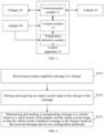
- 10 control apparatus; 20: charger; 30: vehicle; 40: adapter; 11: communication module; 12: control module; 13: temperature detection module; 111: first communication unit; 112: second communication unit; 702: computer device; 704: processor; 706: memory; 708: drive mechanism; 710: input/output module; 712: input device; 714: output device; 716: display device; 718: graphical user interface; 720: network interface; 722: communication link; 724: communication bus.
- a current output from a charger needs to be converted (e.g., alternating current to direct current) by an adapter and then output to a battery of a vehicle to realize charging of a vehicle.
- An existing adapter is a mechanical device only with function of current transmission.
- the current is adjusted by a battery management system (BMS) of a vehicle.
- BMS battery management system
- the vehicle directly communicates with the charging pile, an output current of the charging pile is adjusted by an information interaction between the vehicle and the charging pile, however, a fire hazard may arise due to a current carrying capacity of the adapter is not taken into account during charging, thereby creating a greater potential safety hazard.
- an embodiment of the present disclosure provides a control apparatus for an adapter, which sends corresponding control information to a vehicle in combination with a maximum carrying current of an adapter itself, so as to avoid an excessive current output from a charger from affecting a normal operation of the adapter.
- the control apparatus 10 includes: a communication module 11 and a control module 12.
- the communication module 11 is configured to transmit a message between a charger 20 and a vehicle 30. Charging current information is obtained through forwarding the message between the charger 20 and the vehicle 30, so that the output current is obtained in real time.
- the control module 12 is configured to parse and acquire an output current range of the charger 20 when receiving an output capability message of the charger sent by the charger 20, and send a corresponding message to the vehicle 30 base on a rated current of an adapter 40 and the output current range, so that the vehicle 30 sends a feedback message to the charger 20 based on the received message and an own configuration parameter.
- the output capability message (such as a CML message) sent by the charger 20 is obtained in real time by providing the control apparatus 10 herein, and the output current range of the charger 20 is obtained through the output capability message, so as to determine a relationship between the rated current of the adapter 40 and the output current range, and thus the output capability message is alternatively adjusted, so that the output current range in the output capability message obtained by the vehicle 30 falls within the rated current range, thereby preventing the adapter 40 from operating in a high-current environment, avoiding an occurrence of high-temperature fires, and improving the safety of charging.
- the output capability message such as a CML message
- the rated current of the adapter 40 may be a maximum withstand current of the adapter 40, i.e., a safe current value.
- the adapter 40 operates normally in a current environment below the safe current value, and a continuous operation may not result in overheating.
- the rated current is determined by a terminal and materials of the adapter 40.
- the rated current of the adapter 40 is a given value and the rated current of different adapters 40 is different, which is not limited in the present disclosure.
- the communication module 11 may be a CAN (Controller Area Network) communication module, implements forwarding of message data, e.g., the CAN communication module receives the message data sent by the charger 20 and converts the message data into a CAN level signal and sends to the control module 12, the control module 12 processes the received level signal, and then converts into corresponding message data, and the corresponding message data is forwarded by the CAN communication module to the vehicle 30. A similar processing is also performed on the message data sent by the vehicle 30, which will not be described.
- CAN Controller Area Network
- the control module 12 may include a micro-control unit with a certain computing processing capability, such as an MCU module, achieves a corresponding purpose by storing processing logics and triggering an operation of the processing logic when receiving corresponding data.
- the control module 12 may be a single-chip microcomputer, chips integrated by a plurality of I/O interface, or the like.
- control module 12 includes a first judgment unit, of which the operation principle may involve:
- the communication efficiency between the charger 20 and the vehicle 30 is ensured by directly forwarding a message in addition to the output capability message, and the output capability message may be parsed based on pre-set message parsing rules, e.g., a method of parsing a message is obtained based on a method of generating a message in a communication protocol specified in advance, and since different messages are different in terms of data format and content, whether the message is the output capability message is determined based on message format and content.
- message encapsulated by different communication protocols are in different formats, so a method of judging the output capability message is not limited in the present disclosure.
- the output current range includes: a minimum output current and a maximum output current
- the output capability message sent by the charger 20 to the vehicle 30 is maximum and minimum values of the output current, so that the battery management system (BMS) of the vehicle 30 determines whether the output current falls within the received range of the battery of the vehicle 30, thereby protecting the battery of the vehicle 30.
- BMS battery management system
- the control apparatus 10 for the adapter 40 properly adjusts the output capability message, so that the output current of the charger 20 may not cause additional damage to the adapter 40, thereby protecting the adapter 40 and improving the charging experience.
- the charger 20 may continuously send the output capability message to the vehicle 30 according to a specified frequency, thus the control module 12 selectively adjusts the output capability message based on the received output capability message in combination with the rated current of the adapter 40, so as to ensure that the message data received by the vehicle 30 are all processed data.
- the vehicle 30 may send a feedback message to the charger 20 based on preset feedback rules in combination with an own configuration parameter (such as battery current carrying capacity), so that the charger 20 outputs the current based on the received feedback message.
- the feedback message is an output current message sent by the BMS of the vehicle to the charger 20.
- control module 12 includes: a second judgment module, of which the operation principle can involve:
- the maximum output current in the adjusted output capability message of the charger is equal to the rated current, thus a higher output current of the charger 20 is ensured, the charging efficiency is improved, and the experience of using car is improved.
- the communication module 11 includes: a first communication unit 111 and a second communication unit 112;
- Separate connection and communication with the charger 20 and the vehicle 30 is realized by providing a first communication unit 111 and a second communication unit 112, which ensures that a data processing volume of a single communication unit (such as the first communication unit 111 or the second communication unit 112) is reduced, and improves the efficiency of data conversion and transmission.
- first communication unit 111 and the second communication unit 112 is an implementation of an embodiment of the present disclosure, and may also be implemented by more or less communication units in some other embodiments, which are not limited in the embodiments of the present disclosure.
- the control apparatus 10 may be a hardware equipment with some physical structure and capable of implementing the functional modules, and thus may be provided independently and maintain a communication connection with the charger 20, the adapter 40 and the vehicle 30. Further, the control apparatus 10 is mounted on the adapter 40, e.g., the control apparatus 10 is disposed inside the adapter 40, and the control apparatus 10 may be configured as a part of the adapter 40, so that the functions of the adapter 40 may be enriched, the communication function of the adapter 40 is increased, the adapter 40 protect itself by the own control module 12, thereby improving the application scope of the adapter 40.
- control apparatus 10 is configured on the vehicle 30, the control apparatus 10 may establish a communication link with the BMS of the vehicle, and acquire and save the rated current of the adapter 40 in advance, so as to realize the functions.
- control apparatus 10 may also be provided on the charger 20, so that in practice, the message sent by the charger 20 is actually forwarded to the vehicle 30 by the control apparatus 10, thereby realizing data exchange between the charger 20 and the vehicles 30.
- control apparatus 10 when the control apparatus 10 is provided in the vehicle 30, the functions of the control apparatus 10 can be integrated into the BMS of the vehicle, i.e., the BMS of the vehicle adds the corresponding functions of the control apparatus 10, and achieves the protection of the adapter 40, so that the functions is realized only by adding a software logic, the supplementary of hardware equipment is avoided as much as possible, and the equipment supplementary cost and the modification cost are reduced.
- control apparatus 10 when the control apparatus 10 is mounted on the adapter 40, as illustrated in FIG. 3 , the control apparatus 10 further includes a temperature detection module 13;
- the adapter 40 may be further protected by disposing the temperature detection module 13 on the adapter 40, to avoid overheating from affecting the operation efficiency, or even serious situations such as fire, and the temperature detection module 13 may be a temperature sensor to collect terminal temperatures (DC+ and DC-) of the adapter 40.
- the specific setting positions are not limited in the embodiment of the disclosure.
- the preset threshold value includes: a first threshold value and a second threshold value, and the first threshold value is smaller than the second threshold value;
- the first threshold value may be understood as a boundary value of the adapter 40 to operate normally, and the second threshold value may be understood as a limit value of the adapter 40 in a safe state, so when the temperature of the adapter 40 exceeds the first threshold value and is smaller than the second threshold value, this means that the adapter 40 is no longer within the normal range and needs to be cooled down; when the temperature of the adapter 40 exceeds the second threshold value, this means that the adapter 40 is in a dangerous state, and should be immediately stopped from operation to escape danger.
- the first threshold value and the second threshold value are determined based on an actual design of the adapter 40, such as structure, material, power of the adapter 40.
- the specific values of the first threshold value and the second threshold value are not limited in the present disclosure.
- the preset current may be understood as a derated current value.
- a currently higher current leads to a higher temperature of the adapter 40, so current derating is required to realize a decrease in the temperature of the adapter 40.
- the preset current is not a fixed value, and may be determined according to an actual current and the state of the adapter.
- derating processing rules may be set according to an actual situation, e.g., the currently charging current may be reduced in an equal value according to a specified gradient.
- the reduction value may be increased to improve the cooling efficiency for the adapter 40.
- there may also be other derating processing rules e.g., at an equal rate.
- a specified ratio such as 10%, 20%
- the preset current may also be a fixed value, which is not limited in the embodiment of the present disclosure.
- the adjustment of the received output capability message may be processed simultaneously based on the rated current and temperature data, and the best result after processing is sent to the vehicle 30, for example:
- control apparatus 10 may also include a power module, the power module is electrically connected to an auxiliary power supply of the charger 20, and the power module is configured to charge other functional modules (such as the communication module 11, the control module 12, and the temperature detection module 13 and so on) in the control apparatus 10, alternatively, the modules may be powered by a low voltage environment (12V converted to 5V) through voltage conversion.
- the power module is electrically connected to an auxiliary power supply of the charger 20, and the power module is configured to charge other functional modules (such as the communication module 11, the control module 12, and the temperature detection module 13 and so on) in the control apparatus 10, alternatively, the modules may be powered by a low voltage environment (12V converted to 5V) through voltage conversion.
- FIG. 4 is a schematic diagram illustrating steps of a method of controlling an adapter provided in an embodiment of the present disclosure.
- the present disclosure provides operational steps of the method in the embodiment or flowchart, but may include more or less operational steps based on conventional or non-creative efforts.
- the sequence of steps listed in the embodiments is only one of a plurality of sequences in which steps are performed, and does not represent a unique execution sequence.
- the methods shown in the embodiments or drawings may be executed sequentially or in parallel. Specifically, as illustrated in FIG. 4 , the method may include:
- the method provided herein may obtain the output capability message (such as a CML message) sent by the charger 20 in real time, and obtain the output current range of the charger 20 through the output capability message, so as to determine a relationship between the rated current of the adapter 40 and the output current range, and thus alternatively adjust the output capability message, so that the output current range in the output capability message obtained by the vehicle 30 falls within the rated current range, thereby preventing the adapter 40 from operating in a high-current environment, avoiding an occurrence of high-temperature fires, and improving the safety of charging.
- the output capability message such as a CML message
- the adapter 40 Before operating, the adapter 40 also performs a self-inspection to inspect whether the functional modules (such as the communication module 11, the control module 12 and the temperature detection module 13) in the control apparatus 10 are qualified, such as detecting whether faults such as a short circuit, an open circuit, an abnormal communication, or the like occur. In a case where a fault occurs, an alarm prompt is issued in time, so that the user replaces or repairs the adapter in time.
- the functional modules such as the communication module 11, the control module 12 and the temperature detection module 13
- the output current range includes: a minimum output current and a maximum output current; the determining a message information to the vehicle 30 based on the rated current of the adapter 40 and the output current range includes:
- the output capability message sent by the charger 20 to the vehicle 30 is maximum and minimum values of the output current, so that the battery control system (BMS) of the vehicle determines whether the output current falls within the received range of the battery of the vehicle 30, thereby protecting the battery of the vehicle.
- BMS battery control system
- the control apparatus 10 for the adapter 40 properly adjusts the output capability message, so that the output current of the charger 20 may not cause additional damage to the adapter 40, thereby protecting the adapter 40 and improving the charging experience.
- the operating principle of the control apparatus 10 may involve:
- the method further includes the steps of:
- the operation state of the adapter is monitored in real time by collecting and further processing the operation temperature of the adapter, thereby improving the operation stability and reliability of the adapter.
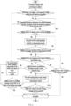
- FIG. 6 is a workflow schematic diagram of the method. The method includes the steps of:
- the embodiment of the present disclosure ensures that the adapter works in the normal operation state, improves the operation efficiency of the adapter and improves the safety of charging, through the whole process of monitoring the temperature of the adapter itself in real time.
- the embodiment of the present disclosure further provides an adapter including: the adapter control apparatus provided above and a current conversion module and.
- the present disclosure also provides a charging system including: a control apparatus for the adapter, a charger 20, a vehicle 30 and an adapter, and the control apparatus may be provided on the charger 20 or on the vehicle or on the adapter.
- a computer device 702 may include one or more processors 704, such as one or more central processing units (CPUs), each of which may implement one or more hardware threads.
- the computer device 702 may also include any memory 706 that is configured to store any type of information such as code, settings, data, or the like.
- a memory 706 may include any one or more combinations of: any type of RAM, any type of ROM, flash memory device, hard disk, optical disk, or the like. More generally, any storage resource may store information by any technology. Further, any storage resource may provide volatile or non-volatile retention for information.
- any storage resource may represent a fixed or removable member of the computer device 702.
- the computer device 702 may execute any operation of the associated instructions.
- the computer device 702 also includes one or more drive mechanisms 708 for interacting with any storage resource, such as a hard disk drive, an optical disk drive, or the like.
- the computer device 702 may also include an I/O module 710 (I/O) configured to receive various inputs (via an input device 712) and to provide various outputs (via an output device 714).
- I/O I/O
- One specific output mechanism may include a display device 716 and an associated graphical user interface (GUI) 718.
- GUI graphical user interface
- the I/O module 710 (I/O), the input device 712 and the output device 714 may not be included, and may only be used as a computer device in the network.
- the computer device 702 may also include one or more network interfaces 720 for exchanging data with other devices via one or more communication links 722.
- One or more communication buses 724 couple together the components described above.
- the communication links 722 may be implemented in any manner, such as via a local area network, a wide area network (such as, the Internet), a point-to-point connection, or any combination thereof.
- the communications link 722 may include any combination of a hardwired link, a wireless link, a router, a gateway function, a name server governed by any or a combination of protocols.
- an embodiment of the present disclosure also provides a computer readable storage media, on which a computer program is stored, and steps of the method are implemented when the computer program is executed by a processor.
- An embodiment of this disclosure also provides a computer readable instruction, and when a processor executes the instruction, a program therein makes the processor implement the method as illustrated in FIGS. 4 to 6 .
- a magnitude of the serial number of the processes does not mean an order of execution, and the order of execution of the processes should be determined by function and inherent logic thereof and should not constitute any limitation on the implementation process of the embodiments herein.
- the disclosed system, apparatus and method may be implemented in other ways.
- the apparatus embodiments described above are only illustrative.
- a division of the units is only a logical function division.
- a plurality of units or components may be combined or integrated into another system, or some features may be ignored, or not implemented.
- the coupling or direct coupling or communication connection with each other shown or discussed may be indirect coupling or communication connection through some interfaces, devices or units, and may be connected electrically, mechanically or otherwise.
- the units described as separate components may or may not be physically separated, and the components shown as units may or may not be physical units, that is, located in one place, or distributed over a plurality of network units. Part or all of the units is selected according to actual needs to achieve the purpose of the solutions in the embodiments herein.
- the functional units in the embodiments herein may be integrated into one processing unit, or each unit may physically exist separately, or two or more units may be integrated into one unit.
- the integrated units may be implemented in the form of hardware or in the form of software functional units.
- the integrated units may be stored in a computer-readable storage media, when realized in the form of a software function unit and sold or used as an independent product.
- the technical solution herein is essentially a part that makes contribution to the prior art, or all or part of the technical solution may be embodied in the form of a software product, and the computer software product is stored in a storage media including a plurality of instructions that enable a computer device (a personal computer, a server, or a network device) to execute all or part of the steps of the method in the embodiments herein.
- the storage media includes: a USB disk, a mobile hard disk, a read-only memory (ROM), a random access memory (RAM), a magnetic disk, an optical disk, or the like, which may store program codes.
Landscapes
- Engineering & Computer Science (AREA)
- Power Engineering (AREA)
- Transportation (AREA)
- Mechanical Engineering (AREA)
- Charge And Discharge Circuits For Batteries Or The Like (AREA)
- Electric Propulsion And Braking For Vehicles (AREA)
Applications Claiming Priority (2)
| Application Number | Priority Date | Filing Date | Title |
|---|---|---|---|
| CN202110839623.8A CN113352929B (zh) | 2021-07-23 | 2021-07-23 | 一种适配器的控制装置、方法、适配器及充电系统 |
| PCT/CN2022/107013 WO2023001232A1 (fr) | 2021-07-23 | 2022-07-21 | Appareil et procédé de commande d'adaptateur, adaptateur et système de charge |
Publications (2)
| Publication Number | Publication Date |
|---|---|
| EP4375128A1 true EP4375128A1 (fr) | 2024-05-29 |
| EP4375128A4 EP4375128A4 (fr) | 2025-08-13 |
Family
ID=77540349
Family Applications (1)
| Application Number | Title | Priority Date | Filing Date |
|---|---|---|---|
| EP22845396.5A Pending EP4375128A4 (fr) | 2021-07-23 | 2022-07-21 | Appareil et procédé de commande d'adaptateur, adaptateur et système de charge |
Country Status (10)
| Country | Link |
|---|---|
| US (1) | US20240317099A1 (fr) |
| EP (1) | EP4375128A4 (fr) |
| JP (1) | JP7689621B2 (fr) |
| KR (1) | KR20240025670A (fr) |
| CN (1) | CN113352929B (fr) |
| BR (1) | BR112024001182A2 (fr) |
| CA (1) | CA3225926A1 (fr) |
| MX (1) | MX2024001095A (fr) |
| WO (1) | WO2023001232A1 (fr) |
| ZA (1) | ZA202400446B (fr) |
Families Citing this family (7)
| Publication number | Priority date | Publication date | Assignee | Title |
|---|---|---|---|---|
| CN113352929B (zh) * | 2021-07-23 | 2023-04-25 | 长春捷翼汽车科技股份有限公司 | 一种适配器的控制装置、方法、适配器及充电系统 |
| US20240416791A1 (en) * | 2021-11-08 | 2024-12-19 | Nissan Motor Co., Ltd. | Charging/discharging control method and charging/discharging control device |
| CN116247762A (zh) * | 2022-12-30 | 2023-06-09 | 南京懂玫驱动技术有限公司 | 充电适配器的充电处理方法及充电适配器 |
| CN115940616B (zh) * | 2023-03-10 | 2023-05-09 | 深圳市澳博森科技有限公司 | 电源适配器自动过热保护方法、装置和智能电源适配器 |
| CN116001632B (zh) * | 2023-03-27 | 2023-06-02 | 合肥艾跑科技有限公司 | 一种具有识别功能的电池充电柜及方法 |
| CN117002303A (zh) * | 2023-05-09 | 2023-11-07 | 安徽全速智能科技有限公司 | 一种新能源温度自检自调节充电桩保护系统 |
| CN119176050B (zh) * | 2024-11-26 | 2025-04-08 | 举视(上海)新能源科技有限公司 | 一种动态功率分配方法及系统 |
Family Cites Families (46)
| Publication number | Priority date | Publication date | Assignee | Title |
|---|---|---|---|---|
| US5369352A (en) * | 1993-04-26 | 1994-11-29 | Ford Motor Company | Universal electric vehicle charging adapter |
| JP2000050522A (ja) | 1998-07-24 | 2000-02-18 | Toshiba Corp | バッテリ充電装置 |
| JP2010530613A (ja) * | 2007-05-10 | 2010-09-09 | オークランド ユニサービシズ リミテッド | 複数の電源を利用する電動車両 |
| WO2009034877A1 (fr) | 2007-09-10 | 2009-03-19 | Toyota Jidosha Kabushiki Kaisha | Chargeur pour véhicule et procédé de charge d'un véhicule |
| US9457791B2 (en) * | 2009-01-06 | 2016-10-04 | GM Global Technology Operations LLC | Charging cable with controller |
| US20090167537A1 (en) | 2007-12-28 | 2009-07-02 | Feliss Norbert A | Minimizing electrical outlet safety failures due to over temperature condition |
| JP2010052861A (ja) | 2008-08-26 | 2010-03-11 | Panasonic Electric Works Co Ltd | 電気自動車充電用コードセット |
| WO2010023527A2 (fr) * | 2008-08-26 | 2010-03-04 | Panasonic Electric Works Co., Ltd. | Ensemble cordon de charge de véhicule électrique |
| DE102009016895A1 (de) | 2009-04-08 | 2010-10-14 | Illinois Tool Works Inc., Glenview | Ladeanschlusseinrichtung für ein elektrisch angetriebenes Kraftfahrzeug |
| US9156362B2 (en) * | 2010-04-09 | 2015-10-13 | Aerovironment, Inc. | Portable charging cable with in-line controller |
| CN101917046B (zh) * | 2010-07-23 | 2013-05-22 | 奇瑞汽车股份有限公司 | 一种充电机及其控制策略 |
| DK3799248T3 (da) * | 2010-10-27 | 2022-09-26 | The Aes Corp | Fremgangsmåde til at styre energitjenester til en flerhed af aktiver af forskellige typer |
| CN101969218A (zh) * | 2010-10-29 | 2011-02-09 | 重庆长安汽车股份有限公司 | 一种纯电动汽车用智能充电方法 |
| US8952656B2 (en) * | 2011-02-04 | 2015-02-10 | Atieva, Inc. | Battery charging station |
| GB2488514A (en) * | 2011-02-11 | 2012-09-05 | Sony Corp | Rule based energy access |
| JP5702180B2 (ja) | 2011-02-14 | 2015-04-15 | 株式会社東光高岳 | 電動移動体の充電装置 |
| ES2451368T3 (es) * | 2011-03-10 | 2014-03-26 | Accenture Global Services Limited | Mejora de red eléctrica de distribución para vehículos eléctricos enchufables |
| WO2012134495A1 (fr) * | 2011-04-01 | 2012-10-04 | Aerovironment, Inc. | Système de gestion et de conversion d'énergie à usages multiples, y compris le chargement de véhicules électriques |
| US20120265362A1 (en) * | 2011-04-14 | 2012-10-18 | Christopher Charles Yasko | Charging device for use with electric vehicles and methods of assembling same |
| GB2489988B (en) * | 2011-04-15 | 2014-06-25 | Nissan Motor Mfg Uk Ltd | Improvements in electrical connections |
| KR101273092B1 (ko) * | 2011-04-28 | 2013-06-10 | 주식회사 엘지화학 | 배터리 충전을 위한 충전 방법 및 충전 장치 |
| DE102011107628A1 (de) * | 2011-06-30 | 2013-01-03 | Rwe Ag | Ladevorrichtung für elektrofahrzeuge und verfahren zum laden von elektrofahrzeugen |
| JP2013034326A (ja) | 2011-08-02 | 2013-02-14 | Toyota Industries Corp | 車両用充電システムおよび車両用充電ケーブル |
| US8384359B2 (en) * | 2011-10-21 | 2013-02-26 | General Electric Company | System, charging device, and method of charging a power storage device |
| WO2014036013A2 (fr) * | 2012-08-27 | 2014-03-06 | Aerovironment, Inc. | Équipement d'alimentation portatif de véhicule électrique |
| DE102012221807A1 (de) * | 2012-11-28 | 2014-05-28 | Bayerische Motoren Werke Aktiengesellschaft | Laden eines elektrischen Energiespeichers eines Elektrofahrzeugs an einer Steckdose mit Reduktion des Ladestroms nach Ausfall und Wiedereinsetzen der Stromversorgung |
| US9337680B2 (en) * | 2013-03-12 | 2016-05-10 | Ford Global Technologies, Llc | Method and system for controlling an electric vehicle while charging |
| CN103559567B (zh) * | 2013-07-18 | 2016-12-28 | 南方电网科学研究院有限责任公司 | 电网对电动汽车充电站的管理系统的管理方法 |
| US20150102775A1 (en) * | 2013-10-15 | 2015-04-16 | Qualcomm Incorporated | Systems, methods, and device for intelligent electric vehicle supply equipment |
| US9056553B2 (en) * | 2013-10-31 | 2015-06-16 | Honda Motor Co., Ltd. | Methods and systems for charging an electric vehicle |
| WO2016069850A1 (fr) * | 2014-10-30 | 2016-05-06 | Google Inc. | Dispositif médiateur pour charger un véhicule électrique intelligent |
| US9573478B2 (en) * | 2014-11-14 | 2017-02-21 | Schneider Electric USA, Inc. | EVSE doubler add-on unit |
| DE102015208786A1 (de) * | 2015-05-12 | 2016-11-17 | Bayerische Motoren Werke Aktiengesellschaft | Kommunikationsmodul für den Ladevorgang eines Fahrzeugs |
| US20170334300A1 (en) * | 2016-05-20 | 2017-11-23 | Faraday&Future Inc. | Charging System with Temperature Sensor |
| EP3266646A1 (fr) * | 2016-07-01 | 2018-01-10 | Hyundai Motor Company | Boîte de commande du câble d'entrée monté sur un câble de charge de véhicule électrique et procédé de charge de véhicule électrique faisant appel à celui-ci |
| CN109416460A (zh) * | 2016-07-12 | 2019-03-01 | 诺华股份有限公司 | 工作距离可变的显微镜 |
| CN107128178B (zh) * | 2017-04-05 | 2019-06-28 | 中通客车控股股份有限公司 | 一种电动客车充电保护系统及方法 |
| CA3289320A1 (en) * | 2017-10-13 | 2025-11-29 | dcbel Inc. | Electric vehicle battery charger |
| WO2019107324A1 (fr) | 2017-11-30 | 2019-06-06 | パナソニック株式会社 | Câble de charge pour véhicule à propulsion électrique et adaptateur de source d'alimentation monté sur un câble de charge pour véhicule à propulsion électrique |
| CN108928252B (zh) * | 2018-07-05 | 2022-01-04 | 蔚来(安徽)控股有限公司 | 充电控制装置和包含其的充电站 |
| JP7091943B2 (ja) | 2018-08-28 | 2022-06-28 | トヨタ自動車株式会社 | 給電システム |
| JP7272772B2 (ja) | 2018-09-28 | 2023-05-12 | トヨタ自動車株式会社 | 車載制御装置及び充電システム |
| JP2019018612A (ja) | 2019-02-05 | 2019-02-07 | 三菱自動車工業株式会社 | 内燃機関の制御装置 |
| CN112248866B (zh) | 2020-11-06 | 2022-04-29 | 长春捷翼汽车零部件有限公司 | 一种电动车辆充电控制装置及方法 |
| CN112406546B (zh) | 2020-11-30 | 2025-09-23 | 长春捷翼汽车科技股份有限公司 | 用电设备充电连接安全检测装置、系统及方法 |
| CN113352929B (zh) * | 2021-07-23 | 2023-04-25 | 长春捷翼汽车科技股份有限公司 | 一种适配器的控制装置、方法、适配器及充电系统 |
-
2021
- 2021-07-23 CN CN202110839623.8A patent/CN113352929B/zh active Active
-
2022
- 2022-07-21 US US18/579,483 patent/US20240317099A1/en active Pending
- 2022-07-21 EP EP22845396.5A patent/EP4375128A4/fr active Pending
- 2022-07-21 BR BR112024001182A patent/BR112024001182A2/pt unknown
- 2022-07-21 KR KR1020247003004A patent/KR20240025670A/ko active Pending
- 2022-07-21 CA CA3225926A patent/CA3225926A1/fr active Pending
- 2022-07-21 WO PCT/CN2022/107013 patent/WO2023001232A1/fr not_active Ceased
- 2022-07-21 JP JP2024504008A patent/JP7689621B2/ja active Active
- 2022-07-21 MX MX2024001095A patent/MX2024001095A/es unknown
-
2024
- 2024-01-12 ZA ZA2024/00446A patent/ZA202400446B/en unknown
Also Published As
| Publication number | Publication date |
|---|---|
| BR112024001182A2 (pt) | 2024-04-30 |
| CN113352929A (zh) | 2021-09-07 |
| JP2024526973A (ja) | 2024-07-19 |
| US20240317099A1 (en) | 2024-09-26 |
| MX2024001095A (es) | 2024-02-23 |
| ZA202400446B (en) | 2024-08-28 |
| CA3225926A1 (fr) | 2023-01-26 |
| CN113352929B (zh) | 2023-04-25 |
| EP4375128A4 (fr) | 2025-08-13 |
| JP7689621B2 (ja) | 2025-06-06 |
| WO2023001232A1 (fr) | 2023-01-26 |
| KR20240025670A (ko) | 2024-02-27 |
Similar Documents
| Publication | Publication Date | Title |
|---|---|---|
| EP4375128A1 (fr) | Appareil et procédé de commande d'adaptateur, adaptateur et système de charge | |
| US11095132B2 (en) | Battery management system | |
| WO2022142036A1 (fr) | Système de charge de véhicule électrique et procédé de commande associé | |
| CN108964201A (zh) | 一种通讯基站用退役动力电池供电系统及方法 | |
| EP4667280A1 (fr) | Procédé et appareil de commande de charge montée sur véhicule, véhicule, système et support de stockage | |
| CN116345622B (zh) | 开关管保护方法、电池包及储能系统 | |
| CN115923586A (zh) | 一种电池系统过电流保护方法及车辆 | |
| CN215897325U (zh) | 一种多路充电dc柜 | |
| CN112886682A (zh) | 一种电动助力车的电池保护系统 | |
| CN116613702A (zh) | 断路器自动重合闸控制系统及断路器自动重合闸控制方法 | |
| WO2020215583A1 (fr) | Système et procédé de surveillance de bloc-batterie | |
| CN118232480A (zh) | 充电保护电路及锂电池系统 | |
| CN106114227B (zh) | 动力电池故障保护方法、装置及动力电池 | |
| WO2024179265A1 (fr) | Appareil de conversion de puissance et système de stockage d'énergie | |
| CN117032186B (zh) | 具备电源异常预警保护功能的控制器系统 | |
| CN107230809B (zh) | 电池包充电保护方法、对应的电池包和电池包充电设备 | |
| CN113555926A (zh) | 一种多路充电dc柜及控制方法 | |
| CN201414022Y (zh) | 一种蓄电池充放电控制系统 | |
| CN116141967A (zh) | 电动车辆供电装置、方法及电动车辆 | |
| CN211731283U (zh) | 一种汽车智能配电盒系统 | |
| CN119176050B (zh) | 一种动态功率分配方法及系统 | |
| CN224123908U (zh) | 电池管理系统 | |
| CN118991433B (zh) | 纯电动汽车蓄电池保险烧蚀检测控制方法、装置及设备 | |
| CN120200336B (zh) | 储能电池单元故障的处理方法及系统 | |
| CN119261557B (zh) | 一种电池故障处理方法、装置、电子设备及存储介质 |
Legal Events
| Date | Code | Title | Description |
|---|---|---|---|
| STAA | Information on the status of an ep patent application or granted ep patent |
Free format text: STATUS: THE INTERNATIONAL PUBLICATION HAS BEEN MADE |
|
| PUAI | Public reference made under article 153(3) epc to a published international application that has entered the european phase |
Free format text: ORIGINAL CODE: 0009012 |
|
| STAA | Information on the status of an ep patent application or granted ep patent |
Free format text: STATUS: REQUEST FOR EXAMINATION WAS MADE |
|
| 17P | Request for examination filed |
Effective date: 20240207 |
|
| AK | Designated contracting states |
Kind code of ref document: A1 Designated state(s): AL AT BE BG CH CY CZ DE DK EE ES FI FR GB GR HR HU IE IS IT LI LT LU LV MC MK MT NL NO PL PT RO RS SE SI SK SM TR |
|
| XX | Miscellaneous (additional remarks) |
Free format text: THE APPLICANT HAS FILED A TEXT WITH WHICH IT IS INTENDED TO BRING THE TRANSLATION INTO CONFORMITY WITH THE APPLICATION AS FILED (ART. 14(2) EPC). |
|
| P01 | Opt-out of the competence of the unified patent court (upc) registered |
Free format text: CASE NUMBER: APP_36003/2024 Effective date: 20240617 |
|
| DAV | Request for validation of the european patent (deleted) | ||
| DAX | Request for extension of the european patent (deleted) | ||
| A4 | Supplementary search report drawn up and despatched |
Effective date: 20250716 |
|
| RIC1 | Information provided on ipc code assigned before grant |
Ipc: B60L 53/66 20190101AFI20250710BHEP Ipc: B60L 53/18 20190101ALI20250710BHEP Ipc: B60L 53/14 20190101ALI20250710BHEP Ipc: B60L 53/62 20190101ALI20250710BHEP Ipc: B60L 53/60 20190101ALI20250710BHEP Ipc: H02J 7/02 20160101ALI20250710BHEP |
|
| GRAP | Despatch of communication of intention to grant a patent |
Free format text: ORIGINAL CODE: EPIDOSNIGR1 |
|
| STAA | Information on the status of an ep patent application or granted ep patent |
Free format text: STATUS: GRANT OF PATENT IS INTENDED |