EP4375230A1 - Füllvorrichtung zum füllen von behältern mit flüssigen produkten - Google Patents
Füllvorrichtung zum füllen von behältern mit flüssigen produkten Download PDFInfo
- Publication number
- EP4375230A1 EP4375230A1 EP22425056.3A EP22425056A EP4375230A1 EP 4375230 A1 EP4375230 A1 EP 4375230A1 EP 22425056 A EP22425056 A EP 22425056A EP 4375230 A1 EP4375230 A1 EP 4375230A1
- Authority
- EP
- European Patent Office
- Prior art keywords
- sterile fluid
- filling
- supply line
- sterile
- nozzle
- Prior art date
- Legal status (The legal status is an assumption and is not a legal conclusion. Google has not performed a legal analysis and makes no representation as to the accuracy of the status listed.)
- Pending
Links
- 238000011049 filling Methods 0.000 title claims abstract description 136
- 239000012263 liquid product Substances 0.000 title claims abstract description 48
- 239000012530 fluid Substances 0.000 claims abstract description 134
- 238000011144 upstream manufacturing Methods 0.000 claims abstract description 7
- 230000000694 effects Effects 0.000 claims abstract description 4
- 239000000047 product Substances 0.000 claims description 14
- IJGRMHOSHXDMSA-UHFFFAOYSA-N Atomic nitrogen Chemical compound N#N IJGRMHOSHXDMSA-UHFFFAOYSA-N 0.000 claims description 8
- 239000011261 inert gas Substances 0.000 claims description 4
- 238000000034 method Methods 0.000 claims description 4
- 229910052757 nitrogen Inorganic materials 0.000 claims description 4
- 238000007599 discharging Methods 0.000 claims description 2
- 238000001035 drying Methods 0.000 claims description 2
- 235000021056 liquid food Nutrition 0.000 description 6
- 235000013361 beverage Nutrition 0.000 description 2
- 239000000356 contaminant Substances 0.000 description 2
- 238000011109 contamination Methods 0.000 description 2
- 235000011389 fruit/vegetable juice Nutrition 0.000 description 2
- 235000013336 milk Nutrition 0.000 description 2
- 239000008267 milk Substances 0.000 description 2
- 210000004080 milk Anatomy 0.000 description 2
- 235000014101 wine Nutrition 0.000 description 2
- 238000012371 Aseptic Filling Methods 0.000 description 1
- 230000000712 assembly Effects 0.000 description 1
- 238000000429 assembly Methods 0.000 description 1
- 238000004140 cleaning Methods 0.000 description 1
- 230000001351 cycling effect Effects 0.000 description 1
- 230000001419 dependent effect Effects 0.000 description 1
- 238000011010 flushing procedure Methods 0.000 description 1
- 235000013305 food Nutrition 0.000 description 1
- 230000036512 infertility Effects 0.000 description 1
- 239000000463 material Substances 0.000 description 1
- 238000012986 modification Methods 0.000 description 1
- 230000004048 modification Effects 0.000 description 1
- 239000010865 sewage Substances 0.000 description 1
- 230000001954 sterilising effect Effects 0.000 description 1
- 238000004659 sterilization and disinfection Methods 0.000 description 1
Images


Classifications
-
- B—PERFORMING OPERATIONS; TRANSPORTING
- B67—OPENING, CLOSING OR CLEANING BOTTLES, JARS OR SIMILAR CONTAINERS; LIQUID HANDLING
- B67C—CLEANING, FILLING WITH LIQUIDS OR SEMILIQUIDS, OR EMPTYING, OF BOTTLES, JARS, CANS, CASKS, BARRELS, OR SIMILAR CONTAINERS, NOT OTHERWISE PROVIDED FOR; FUNNELS
- B67C3/00—Bottling liquids or semiliquids; Filling jars or cans with liquids or semiliquids using bottling or like apparatus; Filling casks or barrels with liquids or semiliquids
- B67C3/02—Bottling liquids or semiliquids; Filling jars or cans with liquids or semiliquids using bottling or like apparatus
- B67C3/22—Details
- B67C3/26—Filling-heads; Means for engaging filling-heads with bottle necks
- B67C3/2608—Filling-heads; Means for engaging filling-heads with bottle necks comprising anti-dripping means
Definitions
- the present invention refers in general to the aseptic filling of containers containing liquid products and, more specifically, to a filling device for filling container assemblies with tubular neck delimiting a product passage for containing liquid food products in sterile conditions.
- Liquid food products such as wine, milk, juices, beverages, etc.
- the container spout provides an opening through which the liquid product is dispensed during the container filling operation.
- the container is typically filled in a filling machine, through a machine filling valve provided with at least one nozzle.
- the nozzle is inserted into the container spout, causing the liquid product to flow through the nozzle into the container.
- the flow of liquid product is stopped and the nozzle is withdrawn from the container spout, usually by moving the valve away from the container.
- the container spout is then sealed to prevent liquid product from leaking out of the container during transporting and handling.
- a drawback of the technical solutions according to the prior art is due to a poor or absent drainability, as well as an extended time needed to achieve the drainage. Additionally, in the prior art filling devices the anti-drip systems are often installed outside of the sterile area. However, drainability is strictly related to cleanability and consequently to sterility, because one of the necessary conditions to grant an efficient sterilization is to secure that all the components of the filling device are properly cleaned first. Time needed to remove residual product from the filling valve at the end of the filling step is a key factor on the overall speed of the filling machine, so minimizing the nozzle cleaning time leads to better performance of the filling machine in terms of output. Anti-drip systems installed outside of the sterile area could suck in airborne contaminants in case of gasket failure or loosening of components.
- One object of the present invention is therefore to provide a filling device for filling containers containing liquid products, in particular but not exclusively liquid food products, which is capable of resolving the drawbacks of the prior art in a simple, inexpensive and particularly functional manner.
- one object of the present invention is to provide a filling device for filling containers containing liquid products which is capable of avoiding, or at least minimizing, the dripping of the respective filling valve by means of full drainability of the filling device.
- Another object of the present invention is to provide a filling device for filling containers containing liquid products wherein the anti-drip system is installed into the sterile area of the filling device.
- the filling device comprises at least one filling valve, which is provided upstream with at least one liquid product supply line, for supplying at least one liquid product to the filling valve, and which is provided downstream with at least one nozzle, for dispensing the liquid product to a container.
- the filling device also comprises at least one sterile fluid supply line, which is hydraulically connected with the filling valve for supplying at least one sterile fluid to the nozzle.
- the filling device also comprises at least one sterile fluid connection conduit, which hydraulically connects the sterile fluid supply line to the filling valve, for supplying to the nozzle the sterile fluid flowing through the sterile fluid supply line.
- the filling device further comprises at least one fluid drainage conduit, which is hydraulically connected downstream of the sterile fluid supply line.
- At least a portion of the sterile fluid supply line, the sterile fluid connection conduit, at least a portion of the filling valve comprising the nozzle, and at least a portion of the fluid drainage conduit form a sterile area of the filling device.
- At least one venturi is placed at an intersection point between the sterile fluid supply line, the sterile fluid connection conduit, and the fluid drainage conduit.
- the venturi hydraulically connects with venturi effect the sterile fluid supply line with the fluid drainage conduit.
- the venturi comprises at least one converging channel, which is placed downstream of the sterile fluid supply line, at least one diverging channel, which is placed downstream of the converging channel and upstream of the fluid drainage conduit, and at least one connection channel, which is placed between the converging channel and the diverging channel, and which hydraulically connects the venturi with the sterile fluid connection conduit.
- the length of the diverging channel is greater than the length of the converging channel.
- connection channel is a channel with a constant internal cross-sectional area.
- the fluid connection conduit is hydraulically connected with the filling valve at the nozzle.
- At least one first flow control valve is preferably placed along the fluid connection conduit, between the venturi and the filling valve. At least one second flow control valve is preferably placed along the fluid drainage conduit, downstream of the venturi.
- the sterile fluid is generated by at least one sterile fluid source, which is hydraulically connected with the sterile fluid supply line and is arranged to inject the sterile fluid into the sterile fluid supply line.
- the sterile fluid is steam.
- the sterile fluid is sterile air.
- the sterile fluid is an inert gas, such as nitrogen.
- the invention is also directed towards a method for operating the filling device described above.
- the method comprises the steps of:
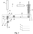
- the filling device 10 is designed to be a part of a filling machine (not shown) for filling containers containing liquid products.
- each container may be of the flexible type, having at least one spout through which the liquid product is dispensed during the container filling operation.
- the filling device 10 comprises at least one filling valve 12, which is provided upstream with at least one liquid product supply line 14 for supplying at least one liquid product P to the filling valve 12.
- the liquid product P is a liquid food product, such as wine, milk, juices, beverages, etc.
- the filling valve 12 is also provided downstream with at least one nozzle 16 for dispensing the liquid product P to a container.
- the filling valve 12 may be of any type known in the state of the art and will therefore not be described in detail hereinafter.
- the filling device 10 also comprises at least one sterile fluid supply line 18, which is hydraulically connected with the filling valve 12 for supplying at least one sterile fluid S to the nozzle 16.
- the sterile fluid S can be generated by at least one sterile fluid source 38, which is hydraulically connected with the sterile fluid supply line 18 and is arranged to inject the sterile fluid S into the sterile fluid supply line 18.
- the sterile fluid S can be steam.
- the steam can be injected into the sterile fluid supply line 18 at a pressure comprised between 2 bar and 2.5 bar.
- the sterile fluid S can be sterile air, or any other suitable sterile fluid, like for example an inert gas such as nitrogen, for flushing filling valves capable of delivering liquid food product.
- the filling device 10 comprises at least one sterile fluid connection conduit 20, which hydraulically connects the sterile fluid supply line 18 to the filling valve 12, for supplying to the nozzle 16 the sterile fluid S flowing through the sterile fluid supply line 18, and at least one fluid drainage conduit 22, which is hydraulically connected downstream of the sterile fluid supply line 18.
- the fluid drainage conduit 22 can hydraulically connect the sterile fluid supply line 18 to a drainage system 24 of known type, such as a drainage tank or a sewage system.
- At least a portion of the sterile fluid supply line 18, the sterile fluid connection conduit 20, at least a portion of the filling valve 12 comprising the nozzle 16, and at least a portion of the fluid drainage conduit 22 form a sterile area A of the filling device 10, wherein potential contamination of the liquid product P must be avoided.
- venturi 26 is placed at an intersection point between the sterile fluid supply line 18, the sterile fluid connection conduit 20, and the fluid drainage conduit 22.
- the venturi 26 hydraulically connects with venturi effect the sterile fluid supply line 18 with the fluid drainage conduit 22.
- the venturi 26 is thus installed into the sterile area A of the filling device 10, very close to the nozzle 16 of the filling valve 12, to minimize the connection piping length, in particular the length of the sterile fluid connection conduit 20.
- At least one first flow control valve 34 is placed along the fluid connection conduit 20, between the venturi 26 and the filling valve 12.
- at least one second flow control valve 36 is placed along the fluid drainage conduit 22, downstream of the venturi 26.
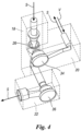
- the venturi 26 can comprise at least one converging channel 28, which is placed downstream of the sterile fluid supply line 18, and at least one diverging channel 30, which is placed downstream of the converging channel 28 and upstream of the fluid drainage conduit 22. Additionally, the venturi 26 can comprise at least one connection channel 32, which is placed between the converging channel 28 and the diverging channel 30. This connection channel 32 hydraulically connects the venturi 26 with the sterile fluid connection conduit 20. This position and configuration of the venturi 26 is such that, when the filling valve 12 is in its "after filling" position (see, for example, Figure 2 ), there is a full drainability of the nozzle 16, since there is a slope from the nozzle 16 to the drainage system 24.
- the length L1 of the diverging channel 30 of the venturi 26 is greater than the length L2 of the converging channel 28 of said venturi 26.
- the connection channel 32 is a channel with a constant internal cross-sectional area.
- the connection channel 32 can be a conventional tubular channel.
- the venturi 26 can have any other shape and/or size different from those shown drawings, according to requirements of the filling valve 12 and/or the filling machine, without departing from the scope of protection of the present invention.
- the fluid connection conduit 20 can be hydraulically connected with the filling valve 12 at the respective nozzle 16. In this way, the full drainability of the nozzle 16 may be improved.
- the venturi 26 Being installed into the sterile area A of the filling device 10, where the sterile fluid S (sterile air, steam, or an inert gas such as nitrogen) flows, in case of gasket failure or loosening parts, the venturi 26 would not suck in potential contaminants, maximizing food safety in case of delivering of liquid food product.
- the advantages of the presence, in the filling device 10 according to the invention, of the venturi 26, as well as its specific position into the sterile area A of this filling device 10, are the full drainability and cleanability of the piping, a high anti-dripping effectiveness of the filling valve 12 and a high-speed cycling of the filling device 10.
- a first step i.e., the filling step, consists in tightly inserting at least the nozzle 16 of the filling valve 12 into a container (not shown).
- the liquid product P supplied by the liquid product supply line 14, can then be delivered into the container.
- the nozzle 16 of the filling valve 12 is closed, while said filling valve 12 is still tightly inserted into the container. In this way, the supplying of the liquid product P into the container is blocked.
- the nozzle 16 Before pulling up the nozzle 16 of the filling valve 12 from the container, the nozzle 16 needs to be cleaned of residual liquid product P.
- the first flow control valve 34 is thus opened, while the second flow control valve 36 is closed (see the first operative condition of the filling device 10 shown in Figure 1 ).
- this operative condition the passage of the sterile fluid S through the sterile fluid supply line 18 and the sterile fluid connection conduit 20 is thus allowed, so as to deliver said sterile fluid S to the nozzle 16 of the filling valve 12.
- vacuum V is generated into the sterile fluid connection conduit 20, by keeping the first flow control valve 34 open and opening the second flow control valve 36 too.
- the nozzle 16 is dried by removing residual product and/or condensate drops from said nozzle 16.
- the dry nozzle 16 of the filling valve 12 can be removed from the container, so as to avoiding the risk of dripping into said container and/or into the sterile area A. If the container is a flexible container provided with a cap, the cap can be placed on the respective spout to seal the container. The residual product and/or the condensate drops are then discharged, through the venturi 26 and the fluid drainage conduit 22, into the drainage system 24.
- the filling device for filling containers containing liquid products of the present invention thus conceived is susceptible in any case of numerous modifications and variants, all falling within the same inventive concept; in addition, all the details can be substituted by technically equivalent elements.
- the materials used, as well as the shapes and size can be of any type according to the technical requirements.
Landscapes
- Filling Of Jars Or Cans And Processes For Cleaning And Sealing Jars (AREA)
Priority Applications (2)
| Application Number | Priority Date | Filing Date | Title |
|---|---|---|---|
| EP22425056.3A EP4375230A1 (de) | 2022-11-25 | 2022-11-25 | Füllvorrichtung zum füllen von behältern mit flüssigen produkten |
| PCT/EP2023/082739 WO2024110549A1 (en) | 2022-11-25 | 2023-11-22 | Filling device for filling containers with liquid products |
Applications Claiming Priority (1)
| Application Number | Priority Date | Filing Date | Title |
|---|---|---|---|
| EP22425056.3A EP4375230A1 (de) | 2022-11-25 | 2022-11-25 | Füllvorrichtung zum füllen von behältern mit flüssigen produkten |
Publications (1)
| Publication Number | Publication Date |
|---|---|
| EP4375230A1 true EP4375230A1 (de) | 2024-05-29 |
Family
ID=85122813
Family Applications (1)
| Application Number | Title | Priority Date | Filing Date |
|---|---|---|---|
| EP22425056.3A Pending EP4375230A1 (de) | 2022-11-25 | 2022-11-25 | Füllvorrichtung zum füllen von behältern mit flüssigen produkten |
Country Status (2)
| Country | Link |
|---|---|
| EP (1) | EP4375230A1 (de) |
| WO (1) | WO2024110549A1 (de) |
Citations (5)
| Publication number | Priority date | Publication date | Assignee | Title |
|---|---|---|---|---|
| DE1171295B (de) * | 1962-03-14 | 1964-05-27 | Holstein & Kappert Maschf | Verfahren und Fuellelement zum Abfuellen von Fluessigkeiten |
| EP0919472A1 (de) | 1997-11-28 | 1999-06-02 | Sasib Processing & Seaming Machinery S.p.a. | Nichttropfender Füllstutzen in einer Maschine zum Füllen von öligen Flüssigkeiten |
| EP0906888B1 (de) * | 1997-09-18 | 2001-07-11 | SEZ Semiconductor-Equipment Zubehör für die Halbleiterfertigung AG | Anordnung zum verhindern des Nachtropfens von Flüssigkeiten aus einer Abgabeöffnung |
| US6311742B1 (en) | 1997-09-01 | 2001-11-06 | Opw Fueling Components Europe B.V. | Fuel dispensing nozzle with anti-drip valve and venturi located in downstream end of the nozzle |
| EP1731426B1 (de) * | 2005-06-10 | 2007-08-22 | INDAG Gesellschaft für Industriebedarf mbH & Co. Betriebs KG | Verfahren und Vorrichtung zum Abfüllen von Flüssigkeiten in Folienbeutel mit einer Tülle |
-
2022
- 2022-11-25 EP EP22425056.3A patent/EP4375230A1/de active Pending
-
2023
- 2023-11-22 WO PCT/EP2023/082739 patent/WO2024110549A1/en not_active Ceased
Patent Citations (5)
| Publication number | Priority date | Publication date | Assignee | Title |
|---|---|---|---|---|
| DE1171295B (de) * | 1962-03-14 | 1964-05-27 | Holstein & Kappert Maschf | Verfahren und Fuellelement zum Abfuellen von Fluessigkeiten |
| US6311742B1 (en) | 1997-09-01 | 2001-11-06 | Opw Fueling Components Europe B.V. | Fuel dispensing nozzle with anti-drip valve and venturi located in downstream end of the nozzle |
| EP0906888B1 (de) * | 1997-09-18 | 2001-07-11 | SEZ Semiconductor-Equipment Zubehör für die Halbleiterfertigung AG | Anordnung zum verhindern des Nachtropfens von Flüssigkeiten aus einer Abgabeöffnung |
| EP0919472A1 (de) | 1997-11-28 | 1999-06-02 | Sasib Processing & Seaming Machinery S.p.a. | Nichttropfender Füllstutzen in einer Maschine zum Füllen von öligen Flüssigkeiten |
| EP1731426B1 (de) * | 2005-06-10 | 2007-08-22 | INDAG Gesellschaft für Industriebedarf mbH & Co. Betriebs KG | Verfahren und Vorrichtung zum Abfüllen von Flüssigkeiten in Folienbeutel mit einer Tülle |
Also Published As
| Publication number | Publication date |
|---|---|
| WO2024110549A1 (en) | 2024-05-30 |
Similar Documents
| Publication | Publication Date | Title |
|---|---|---|
| US6070622A (en) | High speed aseptic filling machine | |
| EP0632775B1 (de) | Vorrichtung und verfahren zum befüllen von behältern | |
| US7647950B2 (en) | Beverage bottling plant with a beverage bottle filling machine for filling beverage bottles, and filling elements for the beverage bottle filling machine | |
| FI87441C (fi) | Foerfarande och anordning foer aseptisk fyllning av en foerpackning med vaetska | |
| EP0056701B1 (de) | Füllvorrichtung für Flüssigkeiten | |
| EP0366269B1 (de) | Aseptische Füllvorrichtung | |
| US9567199B2 (en) | Beverage bottle filling machine for filling bottles with fruit juices, beverage filling element in a beverage bottle filling machine with such beverage filling elements for filling bottles or similar containers with fruit juices, and a beverage bottle filling element for filling bottles or similar containers with fruit juices | |
| CN101479182B (zh) | 用于防故障地控制灌装阀的方法 | |
| US6056208A (en) | Apparatus for preventing dripping from conduit openings | |
| JP7765178B2 (ja) | 容器に充填製品を充填するための装置 | |
| WO2010018850A1 (ja) | 炭酸飲料用無菌充填装置 | |
| US9963335B2 (en) | Method and system for filling containers | |
| KR19990064097A (ko) | 압력하에 있는 액체를 충전하기 위한 장치 | |
| EP2414245B1 (de) | Sicherheitskammer zur verwendung in einer verpackungsmaschine | |
| EP3473590B1 (de) | Verbesserte füllvorrichtung für eine füllmaschine | |
| WO2024110549A1 (en) | Filling device for filling containers with liquid products | |
| EP4660090A1 (de) | Verfahren und füllvorrichtung zum befüllen von flexiblen behältern mit fliessfähigen produkten | |
| CN114940478B (zh) | 容器处理设备及其操作方法 | |
| US6267153B1 (en) | Process for filling containers simultaneously with their sterilization | |
| JPH0471796B2 (de) | ||
| US20250353721A1 (en) | Apparatus for filling containers and associated operating method | |
| WO2011048385A2 (en) | Improvements in or relating to packaging | |
| US20190337796A1 (en) | Product loss reduction by using shotened purge for aseptic tank | |
| CN88101078A (zh) | 包装无菌充注方法及设备 | |
| WO2025099692A1 (en) | System and method for filling containers with liquids |
Legal Events
| Date | Code | Title | Description |
|---|---|---|---|
| PUAI | Public reference made under article 153(3) epc to a published international application that has entered the european phase |
Free format text: ORIGINAL CODE: 0009012 |
|
| STAA | Information on the status of an ep patent application or granted ep patent |
Free format text: STATUS: THE APPLICATION HAS BEEN PUBLISHED |
|
| AK | Designated contracting states |
Kind code of ref document: A1 Designated state(s): AL AT BE BG CH CY CZ DE DK EE ES FI FR GB GR HR HU IE IS IT LI LT LU LV MC ME MK MT NL NO PL PT RO RS SE SI SK SM TR |
|
| STAA | Information on the status of an ep patent application or granted ep patent |
Free format text: STATUS: REQUEST FOR EXAMINATION WAS MADE |
|
| 17P | Request for examination filed |
Effective date: 20241111 |
|
| RBV | Designated contracting states (corrected) |
Designated state(s): AL AT BE BG CH CY CZ DE DK EE ES FI FR GB GR HR HU IE IS IT LI LT LU LV MC ME MK MT NL NO PL PT RO RS SE SI SK SM TR |