EP4375352A1 - Composition de graisse et procédé de production de composition de graisse - Google Patents
Composition de graisse et procédé de production de composition de graisse Download PDFInfo
- Publication number
- EP4375352A1 EP4375352A1 EP22845756.0A EP22845756A EP4375352A1 EP 4375352 A1 EP4375352 A1 EP 4375352A1 EP 22845756 A EP22845756 A EP 22845756A EP 4375352 A1 EP4375352 A1 EP 4375352A1
- Authority
- EP
- European Patent Office
- Prior art keywords
- styrene
- blended
- based polymer
- grease composition
- solvent
- Prior art date
- Legal status (The legal status is an assumption and is not a legal conclusion. Google has not performed a legal analysis and makes no representation as to the accuracy of the status listed.)
- Granted
Links
Images


Classifications
-
- C—CHEMISTRY; METALLURGY
- C10—PETROLEUM, GAS OR COKE INDUSTRIES; TECHNICAL GASES CONTAINING CARBON MONOXIDE; FUELS; LUBRICANTS; PEAT
- C10M—LUBRICATING COMPOSITIONS; USE OF CHEMICAL SUBSTANCES EITHER ALONE OR AS LUBRICATING INGREDIENTS IN A LUBRICATING COMPOSITION
- C10M105/00—Lubricating compositions characterised by the base-material being a non-macromolecular organic compound
- C10M105/56—Lubricating compositions characterised by the base-material being a non-macromolecular organic compound containing nitrogen
- C10M105/68—Amides; Imides
-
- C—CHEMISTRY; METALLURGY
- C10—PETROLEUM, GAS OR COKE INDUSTRIES; TECHNICAL GASES CONTAINING CARBON MONOXIDE; FUELS; LUBRICANTS; PEAT
- C10M—LUBRICATING COMPOSITIONS; USE OF CHEMICAL SUBSTANCES EITHER ALONE OR AS LUBRICATING INGREDIENTS IN A LUBRICATING COMPOSITION
- C10M105/00—Lubricating compositions characterised by the base-material being a non-macromolecular organic compound
- C10M105/02—Well-defined hydrocarbons
- C10M105/04—Well-defined hydrocarbons aliphatic
-
- C—CHEMISTRY; METALLURGY
- C10—PETROLEUM, GAS OR COKE INDUSTRIES; TECHNICAL GASES CONTAINING CARBON MONOXIDE; FUELS; LUBRICANTS; PEAT
- C10M—LUBRICATING COMPOSITIONS; USE OF CHEMICAL SUBSTANCES EITHER ALONE OR AS LUBRICATING INGREDIENTS IN A LUBRICATING COMPOSITION
- C10M107/00—Lubricating compositions characterised by the base-material being a macromolecular compound
- C10M107/02—Hydrocarbon polymers; Hydrocarbon polymers modified by oxidation
-
- C—CHEMISTRY; METALLURGY
- C10—PETROLEUM, GAS OR COKE INDUSTRIES; TECHNICAL GASES CONTAINING CARBON MONOXIDE; FUELS; LUBRICANTS; PEAT
- C10M—LUBRICATING COMPOSITIONS; USE OF CHEMICAL SUBSTANCES EITHER ALONE OR AS LUBRICATING INGREDIENTS IN A LUBRICATING COMPOSITION
- C10M115/00—Lubricating compositions characterised by the thickener being a non-macromolecular organic compound other than a carboxylic acid or salt thereof
- C10M115/08—Lubricating compositions characterised by the thickener being a non-macromolecular organic compound other than a carboxylic acid or salt thereof containing nitrogen
-
- C—CHEMISTRY; METALLURGY
- C10—PETROLEUM, GAS OR COKE INDUSTRIES; TECHNICAL GASES CONTAINING CARBON MONOXIDE; FUELS; LUBRICANTS; PEAT
- C10M—LUBRICATING COMPOSITIONS; USE OF CHEMICAL SUBSTANCES EITHER ALONE OR AS LUBRICATING INGREDIENTS IN A LUBRICATING COMPOSITION
- C10M119/00—Lubricating compositions characterised by the thickener being a macromolecular compound
- C10M119/02—Hydrocarbon polymers; Hydrocarbon polymers modified by oxidation
-
- C—CHEMISTRY; METALLURGY
- C10—PETROLEUM, GAS OR COKE INDUSTRIES; TECHNICAL GASES CONTAINING CARBON MONOXIDE; FUELS; LUBRICANTS; PEAT
- C10M—LUBRICATING COMPOSITIONS; USE OF CHEMICAL SUBSTANCES EITHER ALONE OR AS LUBRICATING INGREDIENTS IN A LUBRICATING COMPOSITION
- C10M123/00—Lubricating compositions characterised by the thickener being a mixture of two or more compounds covered by more than one of the main groups C10M113/00 - C10M121/00, each of these compounds being essential
- C10M123/04—Lubricating compositions characterised by the thickener being a mixture of two or more compounds covered by more than one of the main groups C10M113/00 - C10M121/00, each of these compounds being essential at least one of them being a macromolecular compound
-
- C—CHEMISTRY; METALLURGY
- C10—PETROLEUM, GAS OR COKE INDUSTRIES; TECHNICAL GASES CONTAINING CARBON MONOXIDE; FUELS; LUBRICANTS; PEAT
- C10M—LUBRICATING COMPOSITIONS; USE OF CHEMICAL SUBSTANCES EITHER ALONE OR AS LUBRICATING INGREDIENTS IN A LUBRICATING COMPOSITION
- C10M169/00—Lubricating compositions characterised by containing as components a mixture of at least two types of ingredient selected from base-materials, thickeners or additives, covered by the preceding groups, each of these compounds being essential
- C10M169/06—Mixtures of thickeners and additives
-
- C—CHEMISTRY; METALLURGY
- C10—PETROLEUM, GAS OR COKE INDUSTRIES; TECHNICAL GASES CONTAINING CARBON MONOXIDE; FUELS; LUBRICANTS; PEAT
- C10M—LUBRICATING COMPOSITIONS; USE OF CHEMICAL SUBSTANCES EITHER ALONE OR AS LUBRICATING INGREDIENTS IN A LUBRICATING COMPOSITION
- C10M2205/00—Organic macromolecular hydrocarbon compounds or fractions, whether or not modified by oxidation as ingredients in lubricant compositions
- C10M2205/04—Organic macromolecular hydrocarbon compounds or fractions, whether or not modified by oxidation as ingredients in lubricant compositions containing aromatic monomers, e.g. styrene
- C10M2205/046—Organic macromolecular hydrocarbon compounds or fractions, whether or not modified by oxidation as ingredients in lubricant compositions containing aromatic monomers, e.g. styrene used as thickening agents
-
- C—CHEMISTRY; METALLURGY
- C10—PETROLEUM, GAS OR COKE INDUSTRIES; TECHNICAL GASES CONTAINING CARBON MONOXIDE; FUELS; LUBRICANTS; PEAT
- C10M—LUBRICATING COMPOSITIONS; USE OF CHEMICAL SUBSTANCES EITHER ALONE OR AS LUBRICATING INGREDIENTS IN A LUBRICATING COMPOSITION
- C10M2215/00—Organic non-macromolecular compounds containing nitrogen as ingredients in lubricant Compositions
- C10M2215/10—Amides of carbonic or haloformic acids
- C10M2215/102—Ureas; Semicarbazides; Allophanates
- C10M2215/1026—Ureas; Semicarbazides; Allophanates used as thickening material
-
- C—CHEMISTRY; METALLURGY
- C10—PETROLEUM, GAS OR COKE INDUSTRIES; TECHNICAL GASES CONTAINING CARBON MONOXIDE; FUELS; LUBRICANTS; PEAT
- C10M—LUBRICATING COMPOSITIONS; USE OF CHEMICAL SUBSTANCES EITHER ALONE OR AS LUBRICATING INGREDIENTS IN A LUBRICATING COMPOSITION
- C10M2217/00—Organic macromolecular compounds containing nitrogen as ingredients in lubricant compositions
- C10M2217/04—Macromolecular compounds from nitrogen-containing monomers obtained otherwise than by reactions only involving carbon-to-carbon unsaturated bonds
- C10M2217/045—Polyureas; Polyurethanes
- C10M2217/0456—Polyureas; Polyurethanes used as thickening agents
-
- C—CHEMISTRY; METALLURGY
- C10—PETROLEUM, GAS OR COKE INDUSTRIES; TECHNICAL GASES CONTAINING CARBON MONOXIDE; FUELS; LUBRICANTS; PEAT
- C10N—INDEXING SCHEME ASSOCIATED WITH SUBCLASS C10M RELATING TO LUBRICATING COMPOSITIONS
- C10N2020/00—Specified physical or chemical properties or characteristics, i.e. function, of component of lubricating compositions
- C10N2020/01—Physico-chemical properties
- C10N2020/055—Particles related characteristics
- C10N2020/06—Particles of special shape or size
-
- C—CHEMISTRY; METALLURGY
- C10—PETROLEUM, GAS OR COKE INDUSTRIES; TECHNICAL GASES CONTAINING CARBON MONOXIDE; FUELS; LUBRICANTS; PEAT
- C10N—INDEXING SCHEME ASSOCIATED WITH SUBCLASS C10M RELATING TO LUBRICATING COMPOSITIONS
- C10N2040/00—Specified use or application for which the lubricating composition is intended
- C10N2040/02—Bearings
-
- C—CHEMISTRY; METALLURGY
- C10—PETROLEUM, GAS OR COKE INDUSTRIES; TECHNICAL GASES CONTAINING CARBON MONOXIDE; FUELS; LUBRICANTS; PEAT
- C10N—INDEXING SCHEME ASSOCIATED WITH SUBCLASS C10M RELATING TO LUBRICATING COMPOSITIONS
- C10N2050/00—Form in which the lubricant is applied to the material being lubricated
- C10N2050/10—Form in which the lubricant is applied to the material being lubricated semi-solid; greasy
-
- C—CHEMISTRY; METALLURGY
- C10—PETROLEUM, GAS OR COKE INDUSTRIES; TECHNICAL GASES CONTAINING CARBON MONOXIDE; FUELS; LUBRICANTS; PEAT
- C10N—INDEXING SCHEME ASSOCIATED WITH SUBCLASS C10M RELATING TO LUBRICATING COMPOSITIONS
- C10N2070/00—Specific manufacturing methods for lubricant compositions
Definitions
- the present disclosure relates to a grease composition and a production method of the grease composition.
- This application claims priority based on the international patent application PCT/JP2021/027389 filed on July 21, 2021 , and incorporates all contents described in the above international patent application.
- Grease compositions are used to lubricate sliding parts such as rolling bearings, gears, and so forth.
- Patent Documents 1 to 7 describe grease compositions.
- Grease compositions used for lubrication of rolling bearings, gears, and so forth are required to have good oil retention properties in order to ensure good lubrication. Also, in order to meet needs for energy conservation and high efficiency of rolling bearings, gears, and so forth, the above-mentioned grease compositions are required to be capable of reducing torque. That is to say, there is demand for a grease composition that has good oil retention properties and can also ensure low torque properties when used with rolling bearings, gears, and the like.
- a grease composition according to one aspect of the present disclosure includes a base oil and a thickener.
- the thickener contains a urea compound and a styrene-based polymer, in which a content of the styrene-based polymer is 2% by mass or more and 30% by mass or less as to a total amount of the urea compound and the styrene-based polymer.
- Particles of the thickener that have diameters of 0.2 ⁇ m or more have an average value of diameter of 0.2 ⁇ m or more and 1.0 ⁇ m or less.
- a production method of a grease composition includes providing a styrene-based polymer, an amine compound, an isocyanate compound, a lubricating oil, a first solvent that does not dissolve a urea compound that is generated, and a second solvent that does not dissolve the urea compound that is generated, dissolving or dispersing the amine compound in the first solvent, dissolving or dispersing the isocyanate compound in the second solvent, dissolving or dispersing the styrene-based polymer in one or both of the first solvent and the second solvent, such that a first blended solution containing at least the amine compound and a second blended solution containing at least the isocyanate compound are prepared, blending the first blended solution and the second blended solution, and carrying out reaction of the amine compound and the isocyanate compound, such that a third blended solution containing the styrene-based polymer and the urea compound is generated, and adding the lubricating oil after removing
- a production method of a grease composition includes providing a styrene-based polymer, an amine compound, an isocyanate compound, a first lubricating oil, and a second lubricating oil, dissolving or dispersing the amine compound in the first lubricating oil, dissolving or dispersing the isocyanate compound in the second lubricating oil, dissolving or dispersing the styrene-based polymer in one or both of the first lubricating oil and the second lubricating oil, such that a fourth blended solution containing at least the amine compound and a fifth blended solution containing at least the isocyanate compound are prepared, and blending the fourth blended solution and the fifth blended solution, and carrying out reaction of the amine compound and the isocyanate compound.
- the grease composition according to the present disclosure has excellent oil retention properties.
- the above grease composition contains a urea compound and a predetermined amount of a styrene-based polymer as a thickener, and the particles of the thickener that have diameters of 0.2 ⁇ m or more have an average value of diameter of 0.2 ⁇ m or more and 1.0 ⁇ m or less. That is to say, the grease composition does not contain coarse thickener particles that tend to occur when the urea compound alone is contained therein. Accordingly, the above grease composition retains oil well. In other words, the above grease composition has good oil retention properties. Further, the above grease composition enables rolling bearings, gears, and so forth, to operate with low torque. In other words, the above grease composition has good low torque properties.
- Patent Documents 1 to 7 do not describe that both good oil retention properties and good low torque properties can be achieved through a thickener that contains a urea compound and a predetermined amount of a styrene-based polymer, in which the particles that have diameters of 0.2 ⁇ m or more have an average value of diameter of 0.2 ⁇ m or more and 1.0 ⁇ m or less.
- the grease composition according to the embodiment of the present disclosure can be suitably produced.
- the grease composition according to the present disclosure is used in, for example, dual-pinion type electric power steering systems, column type electric power steering systems, rolling bearings, and so forth.
- FIG. 1 is a configuration diagram schematically illustrating an example of a dual-pinion type electric power steering system 1 including a steering gear device 3.
- FIG. 2 is a sectional view taken along A-A in FIG. 1 , illustrating a portion of the steering gear device 3.
- a lower side of the drawing corresponds to a lower side in a vertical direction when installed in a vehicle.
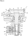
- FIG. 3 is a sectional view taken along B-B in FIG. 1 , illustrating a portion of the steering gear device 3.
- the lower side of the drawing corresponds to the lower side in the vertical direction when installed in the vehicle.
- the dual-pinion type electric power steering system 1 includes a steering wheel 10, a steering shaft 2, a first pinion shaft 32, a rack shaft 31, a housing 33, two rack bushings 30 and 34, two bearings 35 and 36, a first rack guide mechanism 39, and a steering assistance device 5.
- the steering assistance device 5 includes a controller 50, a torque sensor 51, an electric motor 52, a speed reducing mechanism 53, a second pinion shaft 54, two bearings 55 and 56, a worm housing 57, and a second rack guide mechanism 59.
- the speed reducing mechanism 53 includes a worm 531 and a worm wheel 532.
- a driver who drives an automobile equipped with this dual-pinion type electric power steering system 1 performs steering operations by turning the steering wheel 10.
- the steering shaft 2 includes a column shaft 21, a first universal joint 23, an intermediate shaft 22, and a second universal joint 24.
- the first universal joint 23 includes a first yoke that is omitted from illustration, a plurality of first rolling elements that is omitted from illustration, a first joint spider that is omitted from illustration, a plurality of second rolling elements that is omitted from illustration, and a second yoke that is omitted from illustration.
- the second universal joint 24 includes a third yoke that is omitted from illustration, a plurality of third rolling elements that is omitted from illustration, a second joint spider that is omitted from illustration, a plurality of fourth rolling elements that is omitted from illustration, and a fourth yoke that is omitted from illustration.
- the column shaft 21 fixes the steering wheel 10 at one end thereof in an extending direction.
- the column shaft 21 fixes the first yoke of the first universal joint 23 at the other end thereof in the extending direction.
- the column shaft 21 is rotatable about a central axis in the extending direction.
- the first yoke is pivotably fitted to a first pair of trunnions located on the same central axis of the first joint spider via the plurality of first rolling elements.
- the second yoke is pivotably fitted to a second pair of trunnions located on the same central axis of the first joint spider via the plurality of second rolling elements.
- the central axes of the first pair of trunnions and the central axes of the second trunnions intersect at an angle of 90 degrees.
- the first pinion shaft 32, the rack shaft 31, the housing 33, the two rack bushings 30 and 34, a first bearing 35, a second bearing 36, the first rack guide mechanism 39, the electric motor 52, the speed reducing mechanism 53, the second pinion shaft 54, a third bearing 55, a fourth bearing 56, the worm housing 57, and the second rack guide mechanism 59 make up the steering gear device 3 that serves as a rack and pinion type steering device.
- the housing 33 is represented by a hidden outline (long dashed double-short dashed lines), and inside thereof is illustrated.
- the second rack toothed portion 314 has second rack teeth 315 formed on a portion thereof in the circumferential direction, and the other portion thereof in the circumferential direction is a cylindrical face 313 of which a central axis is the extending direction of the rack shaft 31.
- An outer peripheral face of the first cylindrical portion 316, an outer peripheral face of the second cylindrical portion 317, and an outer peripheral face of the third cylindrical portion 318 are each a cylindrical face of which the central axis is in the extending direction of the rack shaft 31.
- the extending direction of the first rack teeth 311 has an angle that is not 90 degrees with respect to the extending direction of the rack shaft.
- the extending direction of the second rack teeth 315 has an angle that is not 90 degrees with respect to the extending direction of the rack shaft 31. With the angle of the first rack teeth 311 with respect to the extending direction of the rack shaft 31 as X, the angle of the second rack teeth 315 with respect to the extending direction of the rack shaft 31 is ⁇ -X.
- the fourth opening 335 is located closer to the other end side in the extending direction of the housing than the first opening 332 is.
- the housing 33 further has a fifth opening 336 and a sixth opening 337.
- the fifth opening 336 is located at approximately the same position in the extending direction of the housing 33 as the first opening 332, in a direction perpendicular to the first opening 332, in a radial direction with the extending direction of the housing 33 as the central axis.
- the sixth opening 337 is located at approximately the same position in the extending direction of the housing 33 as the fourth opening 335, in a direction perpendicular to the fourth opening 335, in a radial direction with the extending direction of the housing 33 as the central axis.
- the first rack guide mechanism 39 is fixed to the housing 33.
- the first rack guide mechanism 39 is fixed to the fifth opening 336.
- the fifth opening 336 is at the cylindrical face 312 side that is the other portion of the first rack toothed portion 310 of the rack shaft 31 in the circumferential direction, at a position where the first pinion shaft 32 meshes with the rack shaft 31, in the extending direction of the housing 33.
- the first rack guide mechanism 39 includes a first support yoke 391, a first sheet member 392, a first coil spring 393, and a first plug 394.
- the first sheet member 392 is interposed between the cylindrical face 312, which is the other portion of the first rack toothed portion 310 of the rack shaft 31 in the circumferential direction, and the cylindrical face of the first support yoke 391.
- the first sheet member 392 is fixed to the first support yoke 391.
- the first sheet member 392 and the cylindrical face 312, which is the other portion of the first rack toothed portion 310 of the rack shaft 31 in the circumferential direction, are capable of sliding contact via the grease composition G.
- the first plug 394 is fixed to the fifth opening 336 of the housing 33.
- the worm wheel 532 is fitted into the fitting portion 544.
- the worm 531 is fixed to an output shaft 521 of the electric motor 52.
- the electric motor 52 is fixed to the worm housing 57.
- the worm housing 57 has a seventh opening 571.
- the output shaft 521 of the electric motor 52 is disposed in internal space of the worm housing 57 via the seventh opening 571.
- the electric motor 52 is fixed to the worm housing 57 so as to close off the seventh opening 571 of the worm housing 57.
- the worm 531 is disposed in internal space of the worm housing 57.
- the worm wheel 532 is disposed in the internal space of the worm housing 57.
- the worm housing 57 has an eighth opening 572 vertically upward, and an assembly of the second pinion shaft 54 and the worm wheel 532 is inserted into the internal space of the worm housing 57 from the eighth opening 572.
- the eighth opening is closed with a lid 58.
- the worm housing 57 has a ninth opening 573 on the opposite side from the eighth opening 572. A portion of the second shaft portion 542 of the second pinion shaft 54, the second pinion toothed portion 540, and the second boss portion 543 protrude from the ninth opening 573 of the worm housing 57.
- the worm housing 57 is fixed to the housing 33.
- the ninth opening 573 of the worm housing 57 and the fourth opening 335 of the housing 33 communicate with each other to seal off the internal space from the external space.
- the second pinion teeth 541 formed on the second pinion toothed portion 540 of the second pinion shaft 54, and the second rack teeth 315 formed on the second rack toothed portion 314 of the rack shaft 31 are capable of rolling-sliding contact via the grease composition G.
- the second pinion teeth 541 and the second rack teeth 315 are meshed with each other via the grease composition G.
- the second rack guide mechanism 59 is fixed to the housing 33.
- the second rack guide mechanism 59 is fixed to the sixth opening 337.
- the sixth opening 337 is at the cylindrical face 313 side that is the other portion of the second rack toothed portion 314 of the rack shaft 31 in the circumferential direction, at a position where the second pinion shaft 54 meshes with the rack shaft 31, in the extending direction of the housing 33.
- the second rack guide mechanism 59 includes a second support yoke 591, a second sheet member 592, a second coil spring 593, and a second plug 594.
- the second sheet member 592 is interposed between the cylindrical face 313, which is the other portion of the second rack toothed portion 314 of the rack shaft 31 in the circumferential direction, and a cylindrical face of the second support yoke 591.
- the second sheet member 592 is fixed to the second support yoke 591.
- the second sheet member 592 and the cylindrical face 313, which is the other portion of the second rack toothed portion 314 of the rack shaft 31 in the circumferential direction, are capable of sliding contact via the grease composition G.
- the second plug 594 is fixed to the sixth opening 337 of the housing 33.
- the second plug 594 is in contact with one end of the second coil spring 593.
- the second support yoke 591 is in contact with the other end of the second coil spring 593.
- the second coil spring 593 is shorter than a free length thereof in a state in which the second plug 594 is fixed to the sixth opening 337.
- the second sheet member 592 is pressed against the rack shaft 31 with respect to the housing 33.
- the torque sensor 51 detects steering torque applied by the driver to the steering wheel 10 through the column shaft 21.
- the speed reducing mechanism 53 is an assembly in which the worm 531 that rotates integrally with the output shaft 521 of the electric motor 52 and the worm wheel 532 that rotates integrally with the second pinion shaft 54 mesh with each other.
- a motor current is supplied to the electric motor 52 from the controller 50.
- the controller 50 controls the electric motor 52 based on the steering torque detected by the torque sensor 51, vehicle speed, and so forth, and transmits rotational force of the output shaft 521 of the electric motor 52, of which speed is reduced by the speed reducing mechanism 53, to the second pinion shaft 54.
- the rotational force of the second pinion shaft 54 is applied from the second pinion teeth 541 to the second rack teeth 315, as a steering assisting force.
- the housing 33 is fixed to an automobile that is omitted from illustration, with the extending direction of the housing 33 aligned with a vehicle-width direction.
- Ball joint sockets 11, 11 are fixed to one end and the other end of the rack shaft 31, respectively, and tie rods 12, 12 connected to these ball joint sockets 11, 11, respectively, are connected to bearing rings of rolling bearings that rotatably support a right and left pair of front wheels 14, 14 via knuckle arms 13, 13. Moving the rack shaft 31 in the linear direction, in the extending direction of the housing 33, steers the right and left front wheels 14, 14, which are steered wheels.
- the grease composition G is sealed within the housing 33.
- the grease composition G is interposed between rolling and sliding faces of the first pinion teeth 321 and rolling and sliding faces of the first rack teeth 311, which are in contact with each other when the first pinion teeth 321 and the first rack teeth 311 mesh with each other, thereby lubricating between the rolling and sliding faces of both.
- the grease composition G is interposed between a sliding face of the first sheet member 392 and a sliding face of the cylindrical face 312, which is the other portion of the first rack toothed portion 310 of the rack shaft 31 in the circumferential direction, where the first sheet member 392 and the rack shaft 31 come into contact by being pressed against each other, thereby lubricating between both sliding faces.
- the grease composition G is interposed between rolling and sliding faces of the second pinion teeth 541 and rolling and sliding faces of the second rack teeth 315, which are in contact with each other when the second pinion teeth 541 and the second rack teeth 315 mesh with each other, thereby lubricating between the rolling and sliding faces of both.
- the grease composition G is interposed between a sliding face of the second sheet member 592 and a sliding face of the cylindrical face 313, which is the other portion of the second rack toothed portion 314 of the rack shaft 31 in the circumferential direction, where the second sheet member 592 and the rack shaft 31 come into contact by being pressed against each other, thereby lubricating between both sliding faces.
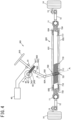
- FIG. 4 is a configuration diagram schematically illustrating an example of a column type electric power steering system 601 including a steering gear device 603.
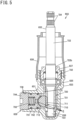
- FIG. 5 is a sectional view taken along A-A in FIG. 4 , illustrating a portion of the steering gear device 603.
- the lower side of the drawing corresponds to the lower side in the vertical direction when installed in a vehicle.
- the column type electric power steering system 601 includes a steering wheel 610, a steering shaft 602, a pinion shaft 632, a rack shaft 631, a housing 633, two rack bushings 630 and 634, two bearings 635 and 636, a rack guide mechanism 639, and a steering assistance device 4.
- a driver who drives an automobile equipped with this column type electric power steering system 601 performs steering operations by turning the steering wheel 610.
- the steering shaft 602 includes a column shaft 621, a first universal joint 623, an intermediate shaft 622, and a second universal joint 624.
- the first universal joint 623 includes a first yoke that is omitted from illustration, a plurality of first rolling elements that is omitted from illustration, a first joint spider that is omitted from illustration, a plurality of second rolling elements that is omitted from illustration, and a second yoke that is omitted from illustration.
- the second universal joint 624 includes a third yoke that is omitted from illustration, a plurality of third rolling elements that is omitted from illustration, a second joint spider that is omitted from illustration, a plurality of fourth rolling elements that is omitted from illustration, and a fourth yoke that is omitted from illustration.
- the column shaft 621 fixes the steering wheel 610 at one end thereof in the extending direction.
- the column shaft 621 fixes the first yoke of the first universal joint 623 at the other end thereof in the extending direction.
- the column shaft 621 is rotatable about a central axis in the extending direction.
- the first yoke is pivotably fitted to a first pair of trunnions located on the same central axis of the first joint spider via the plurality of first rolling elements.
- the second yoke is pivotably fitted to a second pair of trunnions located on the same central axis of the first joint spider via the plurality of second rolling elements.
- the central axes of the first pair of trunnions and the central axes of the second trunnions intersect at an angle of 90 degrees.
- the second yoke of the first universal joint 623 fixes one end of the intermediate shaft 622 in the extending direction thereof.
- the intermediate shaft 622 fixes the third yoke of the second universal joint 624 at the other end thereof in the extending direction.
- the third yoke is pivotably fitted to a third pair of trunnions located on the same central axis of the second joint spider via the plurality of third rolling elements.
- the fourth yoke is pivotably fitted to a fourth pair of trunnions located on the same central axis of the second joint spider via the plurality of fourth rolling elements.
- the central axes of the third pair of trunnions and the central axes of the fourth trunnions intersect at an angle of 90 degrees.
- the fourth yoke of the second universal joint 624 fixes one end of the pinion shaft 632 in the extending direction thereof.
- the column shaft 621 turns about the central axis in the extending direction thereof
- the intermediate shaft 622 also turns about a central axis in the extending direction thereof
- the pinion shaft 632 also turns about a central axis in the extending direction thereof.
- the pinion shaft 632, the rack shaft 631, the housing 633, the two rack bushings 630 and 634, the two bearings 635 and 636, and the rack guide mechanism 639 make up the steering gear device 603 serving as a rack and pinion type steering device.
- the housing 633 is represented by a hidden outline (long dashed double-short dashed line), and inside thereof is illustrated.
- the pinion shaft 632 extends from the upper side to the lower side of the automobile in the vertical direction.
- the pinion shaft 632 includes, from one end side to the other end along the extending direction thereof, a serrated portion 724, a shaft portion 722, a pinion toothed portion 720, and a boss portion 723. Serrations are formed in the serrated portion 724.
- the fourth yoke of the second universal joint 624 is fixed to the serrations of the serrated portion 724.
- the shaft portion 722 has a cylindrical shape.
- Pinion teeth 721 are formed over the entire face of the pinion toothed portion 720 in the circumferential direction.
- An extending direction of the pinion teeth 721 has an angle that is not 90 degrees with respect to the extending direction of the central axis of the pinion shaft 632.
- the boss portion 723 has a cylindrical shape.
- the housing 633 has a first opening 732 on a steering wheel 610 side thereof, and a side opposite to the first opening 732 is sealed off.
- the pinion shaft 632 is accommodated within the housing 633.
- the pinion shaft 632 is rotatably supported by the two bearings 635 and 636, with respect to the housing 633.
- the bearing 635 is a ball bearing.
- the bearing 635 includes an inner ring, an outer ring, and balls, with the inner ring being fixed to the shaft portion 722 and also the outer ring being fixed to the housing 633, and the balls roll between the inner ring and the outer ring.
- the bearing 636 is a roller bearing.
- the bearing 636 includes rollers and an outer ring, with the outer ring being fixed to the housing 633, and the rollers roll on an outer peripheral face of the boss portion 723 and the outer ring.
- a lid 637 through which the pinion shaft 632 passes in a state in which the pinion shaft 632, the two bearings 635 and 636 are inserted into the housing 633, is fixed to the first opening 732 of the housing.
- a seal is fixed to the lid 637, and the seal is slidable on an outer peripheral face 722b of the shaft portion 722 of the pinion shaft 632.
- a cover member 638 is further fixed to the housing 633. The cover member 638 covers a portion of the shaft portion 722 of the pinion shaft 632 from the outside, in the radial direction.
- the rack shaft 631 is provided with, from one end to the other end in an extending direction thereof, a first cylindrical portion 716, a rack toothed portion 710, and a second cylindrical portion 717.
- the rack toothed portion 710 has rack teeth 711 formed on a portion thereof in the circumferential direction, and the other portion thereof in the circumferential direction is a cylindrical face 712 of which a central axis is the extending direction of the rack shaft 631.
- An outer peripheral face of the first cylindrical portion 716 and an outer peripheral face of the second cylindrical portion 717 are each a cylindrical face of which the central axis are in the extending direction of the rack shaft 631.
- the extending direction of the rack teeth 711 has an angle that is not 90 degrees with respect to the extending direction of the rack shaft 631.
- the housing 633 extends in a direction different from the first opening 732 on the steering wheel 610 side, and has a second opening 733 at one end in the extending direction and a third opening 734 at the other end thereof.
- the rack shaft 631 is accommodated within the housing 633, along the direction in which the housing 633 extends.
- One end of the rack shaft 631 in the extending direction thereof protrudes from the second opening 733 at one end of the housing 633 in the extending direction thereof.
- the other end of the rack shaft 631 in the extending direction thereof protrudes from the third opening 734 at the other end of the housing 633 in the extending direction thereof.
- the first rack bushing 630 is fixed to one end of the housing 633 in the extending direction.
- the first rack bushing 630 is fixed to the housing 633, adjacent to the second opening 733.
- the first rack bushing 630 is slidable on the outer peripheral face of the first cylindrical portion 716 of the rack shaft 631.
- a second rack bushing 634 is fixed to the other end of the housing 633 in the extending direction.
- the second rack bushing 634 is fixed to the housing 633, adjacent to the third opening 734.
- the second rack bushing 634 is slidable on the outer peripheral face of the second cylindrical portion 717 of the rack shaft 631.
- the pinion teeth 721 formed on the pinion toothed portion 720 of the pinion shaft 632, and the rack teeth 711 formed on the rack toothed portion 710 of the rack shaft 631 are capable of rolling-sliding contact via the grease composition G.
- the pinion teeth 721 and the rack teeth 711 are meshed with each other via the grease composition G.
- the housing 633 is fixed to an automobile that is omitted from illustration, with the extending direction of the housing 633 aligned with a vehicle-width direction.
- Ball joint sockets 11, 11 are fixed to one end and the other end of the rack shaft 631, respectively, and tie rods 12, 12 connected to these ball joint sockets 11, 11, respectively, are connected to bearing rings of rolling bearings that rotatably support a right and left pair of front wheels 14, 14 via knuckle arms 13, 13. Moving the rack shaft 631 in a linear direction, in the extending direction of the housing 633, steers the right and left front wheels 14, 14, which are steered wheels.
- the rack guide mechanism 639 is fixed to the housing 633.
- the housing 633 has a fourth opening 736 at a cylindrical face 712 side that is the other portion of the rack toothed portion 710 of the rack shaft 631 in the circumferential direction, at a position where the pinion shaft 632 meshes with the rack shaft 631, in the extending direction.
- the rack guide mechanism 639 includes a support yoke 791, a sheet member 792, a coil spring 793, and a plug 794.
- the sheet member 792 is interposed between the cylindrical face 712, which is the other portion of the rack toothed portion 710 of the rack shaft 631 in the circumferential direction, and a cylindrical face of the support yoke 791.
- the sheet member 792 is fixed to the support yoke 791.
- the sheet member 792 and the cylindrical face 712, which is the other portion of the rack toothed portion 710 of the rack shaft 631 in the circumferential direction, are capable of sliding contact via the grease composition G.
- the plug 794 is fixed to the fourth opening 736 of the housing 633.
- the plug 794 is in contact with one end of the coil spring 793.
- the support yoke 791 is in contact with the other end of the coil spring 793.
- the coil spring 793 is shorter than a free length thereof in a state in which the plug 794 is fixed to the fourth opening 736.
- the sheet member 792 is pressed against the rack shaft 631 with respect to the housing 633.
- the steering assistance device 4 includes a controller 40, a torque sensor 41 that detects steering torque applied by the driver to the steering wheel 610, an electric motor 42, and speed reducing mechanism 43 that reduces the rotational force of the output shaft 421 of the electric motor 42 and performs transmission thereof to the column shaft 621.
- the speed reducing mechanism 43 is an assembly in which a worm 431 that rotates integrally with the output shaft 421 of the electric motor 42 and a worm wheel 432 that rotates integrally with the column shaft 621 mesh with each other.
- a motor current is supplied to the electric motor 42 from the controller 40.
- the controller 40 controls the electric motor 42 based on the steering torque detected by the torque sensor 41, vehicle speed, and so forth, and applies the rotational force of the output shaft 421 of the electric motor 42, of which speed is reduced by the speed reducing mechanism 43, to the column shaft 621 as a steering assisting force.
- the grease composition G is sealed within the housing 633.
- the grease composition G is interposed between rolling and sliding faces of the pinion teeth 721 and rolling and sliding faces of the rack teeth 711, which are in contact with each other when the pinion teeth 721 and the rack teeth 711 mesh with each other, thereby lubricating between the rolling and sliding faces of both.
- the grease composition G is interposed between a sliding face of the sheet member 792 and a sliding face of the cylindrical face 712, which is the other portion of the rack toothed portion 710 of the rack shaft 631 in the circumferential direction, where the sheet member 792 and the rack shaft 631 come into contact by being pressed against each other, thereby lubricating between both sliding faces.
- the steering gear device 603 configured in this way has the grease composition according to the present disclosure sealed therein, as the grease composition G.
- the grease composition according to the present disclosure ensures oil retention properties, and accordingly the steering gear device 603 has good seizure resistance and wear resistance.
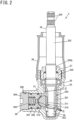
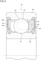
- FIG. 6 is a cross-sectional view of a ball bearing 801, which is an example of a rolling bearing.
- the inner ring 802 has an inner raceway face 821 formed on an outer periphery thereof, on which the balls 804 roll.
- the ball bearing 801 configured in this way has the grease composition according to the present disclosure sealed therein as the grease composition G.
- the grease composition according to the present disclosure ensures oil retention properties, and accordingly the ball bearing 801 has good seizure resistance and wear resistance.
- the grease composition according to the present disclosure can be sealed in and used with the above-described dual-pinion type electric power steering systems, column type electric power steering systems, rolling bearings, and so forth.
- the grease composition according to an embodiment of the present disclosure includes a base oil and a thickener, and the thickener includes a urea compound and a styrene-based polymer.
- the base oil examples include poly- ⁇ -olefin (PAO), ester oil, polyalkylene glycol, fluorine oil, silicone oil, ether oil, and so forth.
- PAO poly- ⁇ -olefin
- poly- ⁇ -olefin examples include oligomerized or polymerized ⁇ -olefins such as 1-hexene, 1-octene, 1-nonene, 1-decene, 1-dodecene, and 1-tetradecene, or the like, and further hydrides thereof.
- PAO4 to PAO8 which are oligomerized 1-decene, are preferable.
- the base oil kinematic viscosity of the base oil at 40°C is preferably 20 mm 2 /s or more and 60 mm 2 /s or less.
- the grease composition is suitable for achieving low torque.
- the thickener is a blended substance containing a urea compound and a styrene-based polymer.
- the grease composition contains a thickener containing a urea compound and a styrene-based polymer, the grease composition has good oil retention properties and is suitable for ensuring low torque performance.
- urea compound examples include urea compounds such as diurea, triurea, tetraurea, and polyurea (excluding diurea, triurea, and tetraurea), and so forth, urea/urethane compounds, urethane compounds such as diurethane and so forth, blended substances thereof, and so forth.
- diurea represented by the following Structural Formula (1) is preferable, with regard to the point that the grease composition has good heat resistance.
- R 1 and R 3 represent amino residues, independently from each other, and R 2 represents a diisocyanate residue.
- Diurea represented by the above Structural Formula (1) is a reaction product of an amine compound and a diisocyanate compound.
- the amine compound may be any one that is known to be an amine compound for synthesizing diurea, which is known as a thickener.
- the diisocyanate compound may be any diisocyanate compound that is known to be a diisocyanate compound for synthesizing diurea, which is known as a thickener.
- examples of the diisocyanate compound include 2,4-toluene diisocyanate (2,4-TDI), 2,6-toluene diisocyanate (2,6-TDI), a blended substance of 2,4-TDI and 2,6-TDI, 4,4'-diphenylmethane diisocyanate (MDI), and so forth.
- the content of the thickener is preferably 10% by mass or more and 40% by mass or less as to the total amount of the base oil and the thickener. The reason thereof is that the grease composition has good low torque properties.
- reaction of the amine compound and the diisocyanate compound can be carried out under various conditions.
- the above reaction may be carried out, for example, (a) in a base oil, or (b) in a solvent.
- the blended substance following the reaction can be used as the grease composition.
- the grease composition can be obtained by removing the solvent to obtain diurea in powder form, following which the diurea in powder form is blended with a base oil. A production method for the grease composition will be described in detail later.
- the styrene-based polymer is a polymer containing styrene or a derivative thereof as a monomer component.
- the styrene-based polymer may be a homopolymer of styrene or a derivative thereof, or a copolymer of a first monomer component selected from among styrene and derivatives thereof and another monomer component.
- the other monomer component may be styrene or a derivative thereof, as long as it is different from the first monomer component.
- Examples of the copolymer include random copolymerization, alternating copolymerization, block copolymerization, and graft copolymers.
- styrene homopolymer examples include atactic polystyrene, isotactic polystyrene, poly-p-methylstyrene, poly-p-ethylstyrene, poly-p-isopropylstyrene, poly- ⁇ -methylstyrene, and so forth.
- Examples of the copolymer include a copolymer of a first monomer component selected from styrene and derivatives thereof, and styrene or a derivative thereof other than the first monomer component.
- Examples of the copolymer also include a copolymer of the first monomer component and an alkadiene.
- Examples of the alkadiene include butadiene, isoprene, pentadiene, hexadiene, and so forth.
- the copolymer is preferably a styrene-isoprene copolymer.
- the number average molecular weight of the styrene-based polymer is preferably 10,000 or more and 500,000 or less, and more preferably 20,000 or more and 200,000 or less. Measurement of the above number average quantity is performed using gel permeation chromatography.
- commercially available products can also be used for the styrene-based polymer.
- Specific examples of commercially available products include Lubrizol (registered trademark) 7306 (manufactured by The Lubrizol Corporation), 7308 of the same, 7460 of the same, Infineum (registered trademark) SV140 (manufactured by Infineum International Limited), 150 of the same, 160 of the same, Septon (registered trademark) 1001 (manufactured by Kuraray Co., Ltd.), 1020 of the same, and so forth.
- the content of the styrene-based polymer is 2% by mass or more and 30% by mass or less as to the total amount of the urea compound and the styrene-based polymer.
- the content of the styrene-based polymer is less than 2% by mass, the grease composition has neither good oil retention properties nor good low torque properties. On the other hand, the oil retention properties of the grease composition will hardly improve even when the content thereof exceeds 30% by mass.
- the content of the styrene-based polymer is preferably 2% by mass or more and 20% by mass or less as to the total amount of the urea compound and the styrene-based polymer, from the perspective of ensuring good oil retention properties and good low torque properties, and more preferably 2% by mass or more and 9% by mass or less.
- the particles of the thickener that have diameters of 0.2 ⁇ m or more have an average value of diameter of 0.2 ⁇ m or more and 1.0 ⁇ m or less.
- the average value of the diameter of the thickener is the average value of the diameter calculated from the volume of the particles, assuming the shape of the particles of the thickener to be a true sphere.
- the urea compound making up the thickener emits fluorescence, and accordingly the urea compound is observed as a fluorescent image.
- the styrene-based polymer is present in a state of being entangled with the urea compound. Accordingly, in the grease composition of the present disclosure, the fluorescence image of the urea compound observed with a confocal laser microscope is regarded as being a fluorescence image of the thickener particles.
- the volume of the thickener particles is measured, the diameter of the thickener particles is calculated from the measured volume assuming the shape of the thickener particles to be a true sphere, and the average value thereof is calculated.
- the average value of the diameter can be calculated using commercially available analysis software.
- the particles of the thickener that have diameters of 0.2 ⁇ m or more have an average value of diameter of 0.2 ⁇ m or more and 1.0 ⁇ m or less, thereby enabling both of ensuring oil retention properties and improving low torque performance.
- the above grease composition may contain additives to the extent that the effects of the invention of the present disclosure are not impaired.
- additives include antioxidants, rust inhibitors, extreme pressure agents, anti-wear agents, dyes, hue stabilizers, viscosity improvers, structural stabilizers, metal deactivators, viscosity index improvers, and so forth.
- the total content of the additives in the grease composition is preferably 10% by mass or less as to the total mass of the base oil and the thickener.
- the grease composition according to the present disclosure can be suitably used, for example, as a grease composition or the like that is sealed in gears such as electric power steering gears or the like of automobiles, rolling bearings, and so forth.
- Methods of producing the grease composition according to the present disclosure include (a) a method of synthesizing a urea compound in a solvent, and thereafter blending the obtained urea compound with a base oil (hereinafter also referred to as production method A), and (b) a method of synthesizing a urea compound in a base oil (hereinafter also referred to as production method B).
- the urea compound can be synthesized by blending an amine compound and an isocyanate compound at a predetermined molar ratio, and causing reaction of the amine compound and the isocyanate compound. Production methods of the above grease composition will be described below by way of an example of a case in which a diisocyanate compound is used as the isocyanate compound, and diurea is synthesized as the urea compound.
- production methods A1 to A3 can be exemplified.
- FIG. 7 is a flowchart for describing a production method A1 of the grease composition.
- each of the solvent A and the solvent B has a boiling point that is lower than that of the provided styrene-based polymer, and is capable of dissolving the styrene-based polymer that is provided.
- the solvent A and the solvent B may be the same or may be different, but are preferably the same.
- a blended solution A containing the solvent A and a blended solution B containing the solvent B are blended in a latter process, the two are blended in a sure manner, which is suitable for promoting the reaction between the amine compound and the diisocyanate compound.
- selection of the removal method and removal conditions is facilitated.
- the blended solution A and the blended solution B may be blended such that 1 mol of the diisocyanate compound is blended as to 2 to 2.2 mol of the amine compound.
- the duration of reaction of the amine compound and the diisocyanate compound is not limited in particular, and may be any duration that allows the reaction to proceed sufficiently. Specifically, the duration may be, for example, 0.2 hours or more and 5 hours or less.
- the blending of the amine compound, the diisocyanate compound, and the styrene-based polymer into their respective solvents, and the blending of the blended solution A and the blended solution B can be carried out using, for example, a mechanical stirrer, a magnet stirrer, or the like.
- a method using a mechanical stirrer is preferable due to facilitating uniform blending of each component.
- base oil is added to the blended substance C containing diurea and styrene-based polymer, and the two are blended (S117).
- Specific examples of the base oil are as described above.
- the blended substance C may be added dropwise to the base oil while stirring the base oil, to blend the two, or the base oil may be added dropwise to the blended substance C while stirring the blended substance C, to blend the two.
- the method of blending the blended substance C and the base oil is not limited in particular, as long as both are blended uniformly, and examples thereof include a method using a mechanical stirrer or a magnetic stirrer, or the like. Among these, a method using a mechanical stirrer is preferable due to facilitating uniform blending of the two.
- the above grease composition can be produced through such processes.
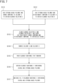
- FIG. 8 is a flowchart for describing a production method A2 of the grease composition.
- (1) predetermined amounts of each of the amine compound, the diisocyanate compound, the styrene-based polymer, the solvent A, and the solvent B are provided.
- Specific examples and suitable examples of the amine compound, the diisocyanate compound, and the styrene-based polymer are as described above.
- the solvent A and the solvent B are the same as those for production method A1.
- the solvent A and the solvent B may be the same or may be different, but are preferably the same.
- the amine compound is added to the solvent A to obtain a blended solution A' (S121).
- the amount of the amine compound may be, for example, 5% by mass or more and 60% by mass or less as to 100% by mass of the solvent A.
- the blending of the amine compound, the diisocyanate compound, and the styrene-based polymer into their respective solvents, and the blending of the blended solution A' and the blended solution B can be carried out using, for example, a mechanical stirrer, a magnet stirrer, or the like.
- a method using a mechanical stirrer is preferable due to facilitating uniform blending of each component.
- the above grease composition can be produced through such processes as well.
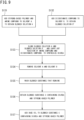
- FIG. 9 is a flowchart for describing a production method A3 of the grease composition.
- (1) predetermined amounts of each of the amine compound, the diisocyanate compound, the styrene-based polymer, the solvent A, and the solvent B are provided.
- Specific examples and suitable examples of the amine compound, the diisocyanate compound, and the styrene-based polymer are as described above.
- the solvent A and the solvent B are the same as those for production method A1.
- the solvent A and the solvent B may be the same or may be different, but are preferably the same.
- the diisocyanate compound is added to the solvent B to obtain a blended solution B' (S 132).
- the amount of the diisocyanate compound can be, for example, 5% by mass or more and 60% by mass or less as to 100% by mass of the solvent B.
- the blending of the amine compound, the diisocyanate compound, and the styrene-based polymer into their respective solvents, and the blending of the blended solution A and the blended solution B' can be carried out using, for example, a mechanical stirrer, a magnet stirrer, or the like.
- a method using a mechanical stirrer is preferable due to facilitating uniform blending of each component.
- the above grease composition can be produced through such processes as well.
- homogenization processing using a roll mill or the like may be performed as necessary, after blending the blended substance C and the base oil.
- necessary additives may be blended therein after blending the base oil and the blended substance C, or the blended substance C and the necessary additives may be blended into the base oil at the same time.
- the process of washing the blended substance (S115, S125, S135) is not an essential process, and may be omitted.
- the base oil may also be added to the blended substance obtained in the process of synthesizing diurea. In this case, the process of adding the base oil to the blended substance C (S1 17, S127, S137) becomes unnecessary.
- Production method A which includes the process of synthesizing diurea in the presence of a styrene-based polymer, is suitable as a method for manufacturing a grease composition that has good oil retention properties and can ensure low torque performance.
- production methods B 1 to B3 can be exemplified.
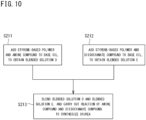
- FIG. 10 is a flowchart for describing a production method B 1 of the grease composition.
- the blended solution D and the blended solution E may be blended at room temperature or under heat.
- the blending of the amine compound, the diisocyanate compound, and the styrene-based polymer into their respective base oils, and the blending of the blended solution D and the blended solution E can be carried out using, for example, a mechanical stirrer, a magnet stirrer, or the like.
- a method using a mechanical stirrer is preferable due to facilitating uniform blending of each component.
- FIG. 11 is a flowchart for describing a production method B2 of the grease composition.
- the blending of the amine compound, the diisocyanate compound, and the styrene-based polymer into their respective base oils, and the blending of the blended solution D' and the blended solution E can be carried out using, for example, a mechanical stirrer, a magnet stirrer, or the like.
- a method using a mechanical stirrer is preferable due to facilitating uniform blending of each component.
- a grease composition containing diurea and styrene-based polymer in the base oil can be produced by going through such processes of (1) to (4) as well.
- FIG. 12 is a flowchart for describing a production method B3 of the grease composition.
- the blending of the amine compound, the diisocyanate compound, and the styrene-based polymer into their respective base oils, and the blending of the blended solution D and the blended solution E' can be carried out using, for example, a mechanical stirrer, a magnet stirrer, or the like.
- a method using a mechanical stirrer is preferable due to facilitating uniform blending of each component.
- a grease composition containing diurea and styrene-based polymer in the base oil can be produced by going through such processes of (1) to (4) as well.
- the amount of styrene-based polymer mixed in the blended solution D and the amount of styrene-based polymer blended in the blended solution E may be the same or may be different.
- the amount of base oil to which the amine compound is added and the amount of base oil to which the isocyanate compound is added may be different.
- the blended solution D' in which the base oil is blended with the amine compound
- the blended solution E' in which the base oil is blended with the diisocyanate compound
- the blended solution D', the blended solution E', and the styrene-based polymer may be blended.
- Production method B which includes the process of synthesizing diurea in the presence of such a styrene-based polymer, is also suitable as a method for manufacturing a grease composition that has good oil retention properties and can ensure low torque performance.
- the amounts of the octylamine and the MDI were set to be such that the mixing ratio of the two (octylamine : MDI) was 2:1 in molar ratio, and the amount of diurea generated was an amount that was 40% by mass as to 100% by mass of the toluene.
- the diurea generated in this example has the following Structural Formula.
- a grease composition was completed in the same way as in Example 1, except for the amount of styrene-isoprene copolymer added being changed such that the amount of styrene-isoprene copolymer contained in the blended substance C was set to be 14.00% by mass as to the total amount of diurea and styrene-isoprene copolymer.
- a grease composition was completed in the same way as in Example 1, except for the amount of styrene-isoprene copolymer added being changed such that the amount of styrene-isoprene copolymer contained in the blended substance C was set to be 1.00% by mass as to the total amount of diurea and styrene-isoprene copolymer.
- the amounts of the octylamine and the MDI were set to be such that the mixing ratio of the two (octylamine : MDI) was 2:1 in molar ratio, and the amount of diurea generated was an amount that was 40% by mass as to 100% by mass of the toluene.
- the blended solution B2 was added dropwise to the blended solution A2 while stirring the blended solution A2 with a mechanical stirrer, thereby blending the two. After the dropwise addition of the blended solution B2 was completed, reaction of the octylamine and the MDI was carried out at room temperature while stirring for 0.5 hours to generate diurea.
- the Structural Formula of the diurea generated in the present Comparative Example 2 is the same as that in Example 1.
- the grease composition produced in Comparative Example 2 does not contain styrene-isoprene copolymers.
- a grease composition was completed in the same way as in Example 1, except that an acrylic-based polymer (alkyl-methacrylate-based copolymer) was mixed in instead of the styrene-isoprene copolymer.
- an acrylic-based polymer alkyl-methacrylate-based copolymer
- the amount of the PAO8 (base oil) was set to be 70.00% by mass as to the total amount of the PAO8, the styrene-isoprene copolymer, and the diurea.
- the amount of the styrene-isoprene copolymer was set to be 7.00% by mass as to the total amount of the styrene-isoprene copolymer and diurea. Thereafter, homogenization processing was performed using a roll mill, thus completing the grease composition.
- the worked penetration (60W) of the grease compositions produced in the Examples and the Comparative Examples was measured by a method conforming to JIS K 2220.
- the oil separation degree of the grease compositions produced in the Examples and the Comparative Examples was measured using a method conforming to JIS K 222011. The results are shown in Table 1. At this time, the sample amount was 10 g, the test temperature was 150°C, and the test duration was 24 hours. The number of samples was 2, and the average value thereof was used as the evaluation result.
- the bearing running torque of the grease compositions prepared in the Examples and the Comparative Examples was measured using a running torque tester under conditions shown in Table 1 below.
- Table 1 The bearing running torque of the grease compositions prepared in the Examples and the Comparative Examples (excluding the grease compositions of Comparative Examples 3, 4, and 6) was measured using a running torque tester under conditions shown in Table 1 below.
- the grease compositions made in the Examples and the Comparative Examples were each applied to a test bearing, which was a 62022RUCM (with non-contact seals on both sides), with the balls and the cage removed from the space surrounded by the inner ring, the outer ring, and the seals, into which space the grease composition was filled in so as to be 35% by volume as to the volume of the space.
- the average particle size of the thickener contained in the grease compositions prepared in the Examples and the Comparative Examples was measured using a confocal laser microscope (TCS SP08, manufactured by Leica Microsystems). At this time, the configuration of the confocal laser microscope shown in Table 2 was employed.
- the particles of the thickener that have diameters of 0.2 ⁇ m or more have an average value of diameter of 0.2 ⁇ m or more and 1.0 ⁇ m or less. It was also revealed that the above grease composition has a low oil separation degree (0.2% or less) and good oil retention properties. It was also revealed that the above grease composition has good low torque properties.
Landscapes
- Chemical & Material Sciences (AREA)
- Oil, Petroleum & Natural Gas (AREA)
- Chemical Kinetics & Catalysis (AREA)
- General Chemical & Material Sciences (AREA)
- Organic Chemistry (AREA)
- Engineering & Computer Science (AREA)
- Power Steering Mechanism (AREA)
- Transmission Devices (AREA)
Applications Claiming Priority (2)
| Application Number | Priority Date | Filing Date | Title |
|---|---|---|---|
| PCT/JP2021/027389 WO2023002626A1 (fr) | 2021-07-21 | 2021-07-21 | Composition de graisse |
| PCT/JP2022/025934 WO2023002820A1 (fr) | 2021-07-21 | 2022-06-29 | Composition de graisse et procédé de production de composition de graisse |
Publications (3)
| Publication Number | Publication Date |
|---|---|
| EP4375352A1 true EP4375352A1 (fr) | 2024-05-29 |
| EP4375352A4 EP4375352A4 (fr) | 2024-06-05 |
| EP4375352B1 EP4375352B1 (fr) | 2025-05-21 |
Family
ID=84979035
Family Applications (1)
| Application Number | Title | Priority Date | Filing Date |
|---|---|---|---|
| EP22845756.0A Active EP4375352B1 (fr) | 2021-07-21 | 2022-06-29 | Composition de graisse et procédé de production de composition de graisse |
Country Status (5)
| Country | Link |
|---|---|
| US (1) | US12344810B2 (fr) |
| EP (1) | EP4375352B1 (fr) |
| JP (1) | JP7838580B2 (fr) |
| CN (1) | CN117836396A (fr) |
| WO (2) | WO2023002626A1 (fr) |
Family Cites Families (16)
| Publication number | Priority date | Publication date | Assignee | Title |
|---|---|---|---|---|
| US5207935A (en) * | 1989-03-31 | 1993-05-04 | Amoco Corporation | Wheel bearing grease |
| DE4131689A1 (de) | 1991-09-24 | 1993-03-25 | Bayer Ag | Verfahren zur herstellung von polyharnstoff-fetten |
| JPH08337790A (ja) * | 1995-06-13 | 1996-12-24 | Nippon Oil Co Ltd | グリース組成物 |
| JP2002327188A (ja) * | 2001-04-27 | 2002-11-15 | Kanto Kasei Kogyo Kk | 非油分離性潤滑剤組成物 |
| JP2004339447A (ja) * | 2003-05-19 | 2004-12-02 | Nsk Ltd | グリース組成物及び転動装置 |
| EP1626061A1 (fr) * | 2004-08-11 | 2006-02-15 | Rhein Chemie Rheinau GmbH | Procédé de fabrication de polyurées pulvérulentes. |
| JP2007297422A (ja) * | 2006-04-27 | 2007-11-15 | Kyodo Yushi Co Ltd | グリース組成物及び機構部品 |
| JP5885157B2 (ja) * | 2011-02-04 | 2016-03-15 | 協同油脂株式会社 | ポリマーアロイを含有するグリース組成物、それを封入した機構部品及びグリース組成物の製造方法 |
| JP5939874B2 (ja) | 2012-04-26 | 2016-06-22 | 三井化学株式会社 | 潤滑剤組成物 |
| JP6022422B2 (ja) | 2013-07-23 | 2016-11-09 | ミネベア株式会社 | ゲル状潤滑剤、転がり軸受、ピボットアッシー軸受及びハードディスクドライブ |
| JP6077610B2 (ja) | 2015-08-07 | 2017-02-08 | ミネベア株式会社 | 樹脂潤滑用グリース組成物 |
| JP6155414B1 (ja) | 2015-12-04 | 2017-06-28 | Nokクリューバー株式会社 | 潤滑剤組成物 |
| WO2019017227A1 (fr) * | 2017-07-21 | 2019-01-24 | 東レ・ダウコーニング株式会社 | Composition de graisse, élément coulissant mettant en œuvre celle-ci, et procédé de réduction de bruit basse fréquence |
| CN110914389A (zh) * | 2018-01-31 | 2020-03-24 | 出光兴产株式会社 | 润滑脂组合物 |
| JP7075877B2 (ja) * | 2018-12-27 | 2022-05-26 | 株式会社イチネンケミカルズ | グリース組成物 |
| JP7389790B2 (ja) | 2019-03-05 | 2023-11-30 | 出光興産株式会社 | グリース組成物、該グリース組成物を用いた摺動機構の潤滑方法及び装置 |
-
2021
- 2021-07-21 WO PCT/JP2021/027389 patent/WO2023002626A1/fr not_active Ceased
-
2022
- 2022-06-29 CN CN202280050789.4A patent/CN117836396A/zh active Pending
- 2022-06-29 WO PCT/JP2022/025934 patent/WO2023002820A1/fr not_active Ceased
- 2022-06-29 EP EP22845756.0A patent/EP4375352B1/fr active Active
- 2022-06-29 US US18/579,569 patent/US12344810B2/en active Active
- 2022-06-29 JP JP2023536666A patent/JP7838580B2/ja active Active
Also Published As
| Publication number | Publication date |
|---|---|
| EP4375352A4 (fr) | 2024-06-05 |
| WO2023002820A1 (fr) | 2023-01-26 |
| JPWO2023002820A1 (fr) | 2023-01-26 |
| WO2023002626A1 (fr) | 2023-01-26 |
| US12344810B2 (en) | 2025-07-01 |
| CN117836396A (zh) | 2024-04-05 |
| EP4375352B1 (fr) | 2025-05-21 |
| US20240327742A1 (en) | 2024-10-03 |
| JP7838580B2 (ja) | 2026-04-01 |
Similar Documents
| Publication | Publication Date | Title |
|---|---|---|
| DE112010000922B4 (de) | Schmierfettzusammensetzung, fettgeschmiertes lager, verwendung des fettgeschmierten lagers, und gelenkkupplung für kardanwelle | |
| EP2617803B1 (fr) | Composition de graisse et roulement | |
| JP6618017B2 (ja) | ウレアグリース | |
| EP3550003B1 (fr) | Graisse mixte | |
| EP3702435B1 (fr) | Procédé de production d'une composition d'huile lubrifiante | |
| CN102746920B (zh) | 润滑脂组合物 | |
| EP4375352B1 (fr) | Composition de graisse et procédé de production de composition de graisse | |
| JP2016204623A (ja) | グリース組成物および当該グリース組成物が封入された転がり軸受 | |
| Gupta et al. | Friction and wear of nanoadditive-based biolubricants in steel–steel sliding contacts: a comparative study | |
| EP4186965B1 (fr) | Matière première pour graisse, procédé de production de matière première de graisse, procédé de production de graisse et graisse | |
| EP3971268B1 (fr) | Procédé de test pour composition d'huile lubrifiante et procédé de production de ladite composition d'huile lubrifiante | |
| EP1498472B1 (fr) | Utilisé d'une composition de graisse lubrifiante pour un palier à roulement | |
| WO2015083695A1 (fr) | Composition de graisse | |
| JP7231046B2 (ja) | グリース組成物および転がり軸受 | |
| EP4317381B1 (fr) | Composition de graisse | |
| US20200407656A1 (en) | Grease composition and rolling bearing | |
| Xiang et al. | Fluorographene with Narrow Lateral Size and Thickness Distributions Prepared for Enhancing Lubrication Performance of Bentonite Grease | |
| WO2007143414A1 (fr) | Méthode de synthèse de zddp fluoré | |
| EP4474450A1 (fr) | Composition de graisse, et dispositif de boîtier de direction | |
| EP4502116A1 (fr) | Graisse | |
| WO2021133583A1 (fr) | Procédé et appareil de production en continu de graisse à base de polyurée | |
| JP7129068B2 (ja) | 潤滑システムおよび潤滑システム用液剤セット | |
| JP6682270B2 (ja) | グリース組成物 | |
| US20200407659A1 (en) | Grease composition and rolling bearing | |
| WO2026094826A1 (fr) | Dispositif de roulement |
Legal Events
| Date | Code | Title | Description |
|---|---|---|---|
| STAA | Information on the status of an ep patent application or granted ep patent |
Free format text: STATUS: THE INTERNATIONAL PUBLICATION HAS BEEN MADE |
|
| PUAI | Public reference made under article 153(3) epc to a published international application that has entered the european phase |
Free format text: ORIGINAL CODE: 0009012 |
|
| STAA | Information on the status of an ep patent application or granted ep patent |
Free format text: STATUS: REQUEST FOR EXAMINATION WAS MADE |
|
| 17P | Request for examination filed |
Effective date: 20240215 |
|
| AK | Designated contracting states |
Kind code of ref document: A1 Designated state(s): AL AT BE BG CH CY CZ DE DK EE ES FI FR GB GR HR HU IE IS IT LI LT LU LV MC MK MT NL NO PL PT RO RS SE SI SK SM TR |
|
| A4 | Supplementary search report drawn up and despatched |
Effective date: 20240506 |
|
| RIC1 | Information provided on ipc code assigned before grant |
Ipc: C10N 50/10 20060101ALI20240429BHEP Ipc: C10M 119/02 20060101ALI20240429BHEP Ipc: C10M 115/08 20060101ALI20240429BHEP Ipc: C10M 107/02 20060101ALI20240429BHEP Ipc: C10M 105/04 20060101ALI20240429BHEP Ipc: C10M 169/06 20060101AFI20240429BHEP |
|
| DAV | Request for validation of the european patent (deleted) | ||
| DAX | Request for extension of the european patent (deleted) | ||
| GRAP | Despatch of communication of intention to grant a patent |
Free format text: ORIGINAL CODE: EPIDOSNIGR1 |
|
| STAA | Information on the status of an ep patent application or granted ep patent |
Free format text: STATUS: GRANT OF PATENT IS INTENDED |
|
| INTG | Intention to grant announced |
Effective date: 20241220 |
|
| GRAS | Grant fee paid |
Free format text: ORIGINAL CODE: EPIDOSNIGR3 |
|
| GRAA | (expected) grant |
Free format text: ORIGINAL CODE: 0009210 |
|
| STAA | Information on the status of an ep patent application or granted ep patent |
Free format text: STATUS: THE PATENT HAS BEEN GRANTED |
|
| RAP3 | Party data changed (applicant data changed or rights of an application transferred) |
Owner name: JTEKT CORPORATION |
|
| RIN1 | Information on inventor provided before grant (corrected) |
Inventor name: MATSUYAMA, JUNYA Inventor name: NIIYA TAKAHARA, KANAKO |
|
| AK | Designated contracting states |
Kind code of ref document: B1 Designated state(s): AL AT BE BG CH CY CZ DE DK EE ES FI FR GB GR HR HU IE IS IT LI LT LU LV MC MK MT NL NO PL PT RO RS SE SI SK SM TR |
|
| REG | Reference to a national code |
Ref country code: GB Ref legal event code: FG4D |
|
| REG | Reference to a national code |
Ref country code: CH Ref legal event code: EP |
|
| REG | Reference to a national code |
Ref country code: DE Ref legal event code: R096 Ref document number: 602022015063 Country of ref document: DE |
|
| REG | Reference to a national code |
Ref country code: IE Ref legal event code: FG4D |
|
| PGFP | Annual fee paid to national office [announced via postgrant information from national office to epo] |
Ref country code: DE Payment date: 20250523 Year of fee payment: 4 |
|
| PGFP | Annual fee paid to national office [announced via postgrant information from national office to epo] |
Ref country code: FR Payment date: 20250627 Year of fee payment: 4 |
|
| PGFP | Annual fee paid to national office [announced via postgrant information from national office to epo] |
Ref country code: AT Payment date: 20250721 Year of fee payment: 4 |
|
| REG | Reference to a national code |
Ref country code: NL Ref legal event code: MP Effective date: 20250521 |
|
| PG25 | Lapsed in a contracting state [announced via postgrant information from national office to epo] |
Ref country code: FI Free format text: LAPSE BECAUSE OF FAILURE TO SUBMIT A TRANSLATION OF THE DESCRIPTION OR TO PAY THE FEE WITHIN THE PRESCRIBED TIME-LIMIT Effective date: 20250521 Ref country code: PT Free format text: LAPSE BECAUSE OF FAILURE TO SUBMIT A TRANSLATION OF THE DESCRIPTION OR TO PAY THE FEE WITHIN THE PRESCRIBED TIME-LIMIT Effective date: 20250922 Ref country code: ES Free format text: LAPSE BECAUSE OF FAILURE TO SUBMIT A TRANSLATION OF THE DESCRIPTION OR TO PAY THE FEE WITHIN THE PRESCRIBED TIME-LIMIT Effective date: 20250521 |
|
| REG | Reference to a national code |
Ref country code: LT Ref legal event code: MG9D |
|
| PG25 | Lapsed in a contracting state [announced via postgrant information from national office to epo] |
Ref country code: NO Free format text: LAPSE BECAUSE OF FAILURE TO SUBMIT A TRANSLATION OF THE DESCRIPTION OR TO PAY THE FEE WITHIN THE PRESCRIBED TIME-LIMIT Effective date: 20250821 Ref country code: GR Free format text: LAPSE BECAUSE OF FAILURE TO SUBMIT A TRANSLATION OF THE DESCRIPTION OR TO PAY THE FEE WITHIN THE PRESCRIBED TIME-LIMIT Effective date: 20250822 |
|
| PG25 | Lapsed in a contracting state [announced via postgrant information from national office to epo] |
Ref country code: NL Free format text: LAPSE BECAUSE OF FAILURE TO SUBMIT A TRANSLATION OF THE DESCRIPTION OR TO PAY THE FEE WITHIN THE PRESCRIBED TIME-LIMIT Effective date: 20250521 Ref country code: PL Free format text: LAPSE BECAUSE OF FAILURE TO SUBMIT A TRANSLATION OF THE DESCRIPTION OR TO PAY THE FEE WITHIN THE PRESCRIBED TIME-LIMIT Effective date: 20250521 |
|
| PG25 | Lapsed in a contracting state [announced via postgrant information from national office to epo] |
Ref country code: BG Free format text: LAPSE BECAUSE OF FAILURE TO SUBMIT A TRANSLATION OF THE DESCRIPTION OR TO PAY THE FEE WITHIN THE PRESCRIBED TIME-LIMIT Effective date: 20250521 |
|
| PG25 | Lapsed in a contracting state [announced via postgrant information from national office to epo] |
Ref country code: HR Free format text: LAPSE BECAUSE OF FAILURE TO SUBMIT A TRANSLATION OF THE DESCRIPTION OR TO PAY THE FEE WITHIN THE PRESCRIBED TIME-LIMIT Effective date: 20250521 |
|
| PG25 | Lapsed in a contracting state [announced via postgrant information from national office to epo] |
Ref country code: RS Free format text: LAPSE BECAUSE OF FAILURE TO SUBMIT A TRANSLATION OF THE DESCRIPTION OR TO PAY THE FEE WITHIN THE PRESCRIBED TIME-LIMIT Effective date: 20250821 |
|
| PG25 | Lapsed in a contracting state [announced via postgrant information from national office to epo] |
Ref country code: IS Free format text: LAPSE BECAUSE OF FAILURE TO SUBMIT A TRANSLATION OF THE DESCRIPTION OR TO PAY THE FEE WITHIN THE PRESCRIBED TIME-LIMIT Effective date: 20250921 |
|
| PG25 | Lapsed in a contracting state [announced via postgrant information from national office to epo] |
Ref country code: LV Free format text: LAPSE BECAUSE OF FAILURE TO SUBMIT A TRANSLATION OF THE DESCRIPTION OR TO PAY THE FEE WITHIN THE PRESCRIBED TIME-LIMIT Effective date: 20250521 |
|
| REG | Reference to a national code |
Ref country code: AT Ref legal event code: MK05 Ref document number: 1796772 Country of ref document: AT Kind code of ref document: T Effective date: 20250521 |
|
| PG25 | Lapsed in a contracting state [announced via postgrant information from national office to epo] |
Ref country code: DK Free format text: LAPSE BECAUSE OF FAILURE TO SUBMIT A TRANSLATION OF THE DESCRIPTION OR TO PAY THE FEE WITHIN THE PRESCRIBED TIME-LIMIT Effective date: 20250521 Ref country code: SM Free format text: LAPSE BECAUSE OF FAILURE TO SUBMIT A TRANSLATION OF THE DESCRIPTION OR TO PAY THE FEE WITHIN THE PRESCRIBED TIME-LIMIT Effective date: 20250521 Ref country code: AT Free format text: LAPSE BECAUSE OF FAILURE TO SUBMIT A TRANSLATION OF THE DESCRIPTION OR TO PAY THE FEE WITHIN THE PRESCRIBED TIME-LIMIT Effective date: 20250521 |
|
| PG25 | Lapsed in a contracting state [announced via postgrant information from national office to epo] |
Ref country code: CZ Free format text: LAPSE BECAUSE OF FAILURE TO SUBMIT A TRANSLATION OF THE DESCRIPTION OR TO PAY THE FEE WITHIN THE PRESCRIBED TIME-LIMIT Effective date: 20250521 |
|
| PG25 | Lapsed in a contracting state [announced via postgrant information from national office to epo] |
Ref country code: EE Free format text: LAPSE BECAUSE OF FAILURE TO SUBMIT A TRANSLATION OF THE DESCRIPTION OR TO PAY THE FEE WITHIN THE PRESCRIBED TIME-LIMIT Effective date: 20250521 |
|
| PG25 | Lapsed in a contracting state [announced via postgrant information from national office to epo] |
Ref country code: SK Free format text: LAPSE BECAUSE OF FAILURE TO SUBMIT A TRANSLATION OF THE DESCRIPTION OR TO PAY THE FEE WITHIN THE PRESCRIBED TIME-LIMIT Effective date: 20250521 |
|
| REG | Reference to a national code |
Ref country code: CH Ref legal event code: H13 Free format text: ST27 STATUS EVENT CODE: U-0-0-H10-H13 (AS PROVIDED BY THE NATIONAL OFFICE) Effective date: 20260127 |
|
| PG25 | Lapsed in a contracting state [announced via postgrant information from national office to epo] |
Ref country code: IT Free format text: LAPSE BECAUSE OF FAILURE TO SUBMIT A TRANSLATION OF THE DESCRIPTION OR TO PAY THE FEE WITHIN THE PRESCRIBED TIME-LIMIT Effective date: 20250521 |
|
| PG25 | Lapsed in a contracting state [announced via postgrant information from national office to epo] |
Ref country code: LU Free format text: LAPSE BECAUSE OF NON-PAYMENT OF DUE FEES Effective date: 20250629 |
|
| PG25 | Lapsed in a contracting state [announced via postgrant information from national office to epo] |
Ref country code: MC Free format text: LAPSE BECAUSE OF FAILURE TO SUBMIT A TRANSLATION OF THE DESCRIPTION OR TO PAY THE FEE WITHIN THE PRESCRIBED TIME-LIMIT Effective date: 20250521 |
|
| REG | Reference to a national code |
Ref country code: DE Ref legal event code: R097 Ref document number: 602022015063 Country of ref document: DE |
|
| REG | Reference to a national code |
Ref country code: BE Ref legal event code: MM Effective date: 20250630 |
|
| PG25 | Lapsed in a contracting state [announced via postgrant information from national office to epo] |
Ref country code: RO Free format text: LAPSE BECAUSE OF FAILURE TO SUBMIT A TRANSLATION OF THE DESCRIPTION OR TO PAY THE FEE WITHIN THE PRESCRIBED TIME-LIMIT Effective date: 20250521 |
|
| PLBE | No opposition filed within time limit |
Free format text: ORIGINAL CODE: 0009261 |
|
| STAA | Information on the status of an ep patent application or granted ep patent |
Free format text: STATUS: NO OPPOSITION FILED WITHIN TIME LIMIT |
|
| REG | Reference to a national code |
Ref country code: CH Ref legal event code: L10 Free format text: ST27 STATUS EVENT CODE: U-0-0-L10-L00 (AS PROVIDED BY THE NATIONAL OFFICE) Effective date: 20260402 |
|
| PG25 | Lapsed in a contracting state [announced via postgrant information from national office to epo] |
Ref country code: IE Free format text: LAPSE BECAUSE OF NON-PAYMENT OF DUE FEES Effective date: 20250629 |
|
| PG25 | Lapsed in a contracting state [announced via postgrant information from national office to epo] |
Ref country code: BE Free format text: LAPSE BECAUSE OF NON-PAYMENT OF DUE FEES Effective date: 20250630 |
|
| PG25 | Lapsed in a contracting state [announced via postgrant information from national office to epo] |
Ref country code: CH Free format text: LAPSE BECAUSE OF NON-PAYMENT OF DUE FEES Effective date: 20250630 |
|
| 26N | No opposition filed |
Effective date: 20260224 |