EP4375433B1 - Toilettenvorrichtung zur kopplung an eine toilettenschüssel und toilette mit der toilettenvorrichtung - Google Patents
Toilettenvorrichtung zur kopplung an eine toilettenschüssel und toilette mit der toilettenvorrichtung Download PDFInfo
- Publication number
- EP4375433B1 EP4375433B1 EP22383140.5A EP22383140A EP4375433B1 EP 4375433 B1 EP4375433 B1 EP 4375433B1 EP 22383140 A EP22383140 A EP 22383140A EP 4375433 B1 EP4375433 B1 EP 4375433B1
- Authority
- EP
- European Patent Office
- Prior art keywords
- toilet
- wall portion
- toilet bowl
- toilet device
- contact surface
- Prior art date
- Legal status (The legal status is an assumption and is not a legal conclusion. Google has not performed a legal analysis and makes no representation as to the accuracy of the status listed.)
- Active
Links
Images





Classifications
-
- E—FIXED CONSTRUCTIONS
- E03—WATER SUPPLY; SEWERAGE
- E03D—WATER-CLOSETS OR URINALS WITH FLUSHING DEVICES; FLUSHING VALVES THEREFOR
- E03D9/00—Sanitary or other accessories for lavatories ; Devices for cleaning or disinfecting the toilet room or the toilet bowl; Devices for eliminating smells
- E03D9/08—Devices in the bowl producing upwardly-directed sprays; Modifications of the bowl for use with such devices ; Bidets; Combinations of bowls with urinals or bidets; Hot-air or other devices mounted in or on the bowl, urinal or bidet for cleaning or disinfecting
Definitions
- the present invention generally relates, in a first aspect, to a toilet device to be coupled to a toilet bowl, and more particularly to a toilet device comprising coupling means adapted for providing a firm and simple coupling to toilet bowl wall portions having different thicknesses.
- the present invention also relates to a toilet comprising a toilet bowl and coupled thereto the toilet device of the first aspect.
- Toilet devices to be coupled to a toilet bowl which comprise the features of the preamble of claim 1 are known in the art.
- those known toilet devices comprise coupling means which are complex and are not adapted to different toilet bowls, particularly to toilet bowl wall portions having different thicknesses.
- the present invention relates, in a first aspect, to a toilet device to be coupled to a toilet bowl, comprising coupling means including a kinematic chain configured to couple the toilet device to said toilet bowl.
- the kinematic chain comprises a pivotable coupling lever and an actuator configured and arranged to act on the pivotable coupling lever to pivot the same about a pivot axis between several angular coupling positions, wherein the pivotable coupling lever has at least one first end portion arranged opposite to a contact surface of the toilet device to trap, between the at least one first end portion and said contact surface, a wall portion of the toilet bowl pressing against two opposed outer surfaces of that wall portion, at least when at one of said several angular positions.
- the toilet device of the first aspect of the present invention enables being coupled to toilet bowl wall portions having different thicknesses (whether of distinct toilet bowls or of different regions of the same toilet bowl), particularly by the several angular coupling positions provided by the pivotable coupling lever, some of which will allow the toilet device to be coupled to thinner toilet bowl wall portions and other to thicker toilet bowl wall portions.
- the pivotable coupling lever of the toilet device of the first aspect of the invention eases its mounting to the toilet bowl, without having to drill into the toilet bowl wall portion, and remains concealed.
- At least part of the pivoting coupling lever is elastically deformable to trap, between the at least one first end portion and the above mentioned contact surface, any of a plurality of toilet bowl wall portions having different thicknesses, for the same one of said several angular positions.
- toilet bowl wall portions of different thicknesses can be trapped between the at least one first end portion of the pivotable coupling lever and the contact surface of the toilet device, only by elastically deforming that part of the pivoting coupling lever, without further pivoting the same, i.e., for the same angular position.
- the toilet device comprises a further contact surface to contact a further wall portion of the toilet bowl, and the actuator is further configured and arranged to couple said further contact surface to the further wall portion of the toilet bowl once the pivotable coupling lever has been pivoted to at least one of said several angular positions.
- a double coupling function is performed by the actuator, namely acting on the pivotable lever to make it pivot to trap and thus couple to the toilet bowl wall portion, and also to couple said further contact surface to the toilet bowl further wall portion.
- the toilet device further comprises an abutment contact surface transversally extending from an end of the contact surface, and configured and arranged to, when the wall portion of the toilet bowl is trapped between the at least one first end portion and the contact surface, firmly abut against an edge at which the two opposed outer faces of the wall portion end.
- the toilet device comprises a housing including a base, said base comprising an articulation at which the pivoting coupling lever is hinged to pivot about said pivot axis, so that the pivoting coupling lever remains, when the toilet device is coupled to the toilet bowl, within an opening of the toilet bowl for all said several angular positions, particularly within an opening partially demarcated and surrounded by the wall portion.
- the base is not configured to be inserted into that opening of the toilet bowl but to rest on one of the outer faces of the wall portion around the contour of that opening.
- the base is configured to be, when coupled to the toilet bowl, partially inserted into that opening of the toilet bowl.
- the above mentioned contact surface and/or further contact surface and/or abutment contact surface are/is defined at an outer face of the base of that housing.
- the toilet bowl wall portion is located at a front region of the contour of that opening of the toilet bowl, and the toilet bowl further wall portion at a back region thereof.
- the actuator comprises at least one member traversing a through opening of the base and is movable in a guided manner therethrough transversally to the pivotable coupling lever to push the same by a second end thereof to pivot the pivotable coupling lever about the pivot axis between the above mentioned several angular positions, said at least one member having a first portion to be accessed by a user.
- the actuator further comprises at least one coupling element attached to the first portion of said at least one member, at least a first end of the at least one coupling element being able to be inserted into a hole of the further contact surface (and therefore, of the wall including that further contact surface) of the toilet device, and the at least one coupling element being configured and arranged to be accessed by a user by a second end, opposite to said first end, to longitudinally push the same to introduce further the at least one coupling element into said hole up to a desired position, and thus move said at least one member through the through opening of the base.
- the first end of the at least one coupling element is configured to also be inserted into a hole of the further wall portion of the toilet bowl, and has a coupling configuration to be coupled to the further wall portion of the toilet bowl at the desired position.
- the at least one coupling element has that coupling configuration to be coupled inside the hole of the further wall portion, or to a lower face of that further wall, or to a further element (such as a nut, joint washer, or other type of fastener) placed after that hole ("after" in the insertion direction).
- the at least one coupling element is a screw to be screwed by the user into the hole of the further wall portion of the toilet bowl, said coupling configuration being a threaded profile of the at least one screw which cooperates with a respective threaded profile inside the hole (defined in the inner contour of the hole or into an anchor plug fit thereinto), to retain the at least one screw into the desired position, said hole of the further wall portion and the hole of the further contact surface being axially coaligned.
- an anchor plug without a threaded profile (such as an expansion anchor plug) is fit into the hole of the further wall portion, the at least one screw being screwed into that anchor plug.
- the hole of the further wall portion does not have a threaded profile, and the threaded profile of the at least one screw cooperates with a respective threaded profile inside a nut (or similar element) placed after that hole ("after" in the screwing direction), the hole of that nut being axially aligned with the holes of the further wall portion and further contact surface.
- the at least one coupling element has at least one elastically deformably arm, the coupling configuration being a retention tab placed at the end of the at least one elastically deformably arm, so that the coupling process is carried out by elastically deforming the at least one elastically deformably arm while introducing said retention tab into the hole of the further wall portion, and once the retention tab has completely passed through that hole the elastically deformable arm elastically recovers its non-deformed shape so that the retention tab abuts against a lower face of the further wall portion (or of a separate intermediate part) thus retaining and coupling the at least one coupling element to that further wall portion.
- the coupling configuration being a retention tab placed at the end of the at least one elastically deformably arm, so that the coupling process is carried out by elastically deforming the at least one elastically deformably arm while introducing said retention tab into the hole of the further wall portion, and once the retention tab has completely passed through that hole the elastically deformable arm elastically recovers its non-deformed shape so that the
- the contact surface and the hole of the further contact surface are located at or near respective opposite ends of the base.
- the at least one member of the actuator further comprises a second portion, which is the one which is movable in a guided manner through the through opening of said base, said first and second portions of the at least one member being, for an implementation of that embodiment, mutually orthogonally arranged so that the at least one member has an inverted L-shape.
- the length of that second portion is variable in order to enable the adaptation of the toilet device to different toilet bowl wall portion thicknesses.
- "Variable" means here, depending on the embodiment, that said second portion is indeed adjustable in length and also that there are several members of the actuator with second portions with different lengths and the most appropriate one is selected for a specific toilet bowl based on the toilet bowl wall portion thickness.
- the housing further comprises a cover removable attached to the base by attaching means accessible to a user to attach/detach said cover to/from the base without the need of uncoupling the base of the toilet device from the toilet bowl.
- the cover of the housing comprises a pivot axis for a toilet seat cover assembly.
- the present invention also relates, in a second aspect to a toilet comprising:
- the toilet bowl comprises the above mentioned opening of the toilet bowl and further wall portion, and the wall portion and further wall portion partially demarcate and surround different areas of the opening of the toilet bowl, the toilet device being coupled to the toilet bowl also by the at least one coupling element of the actuator coupling the further contact surface of the toilet device to the further wall portion once the pivotable coupling lever has been pivoted to at least one of the several angular positions.
- the toilet device is a washing device for a toilet adapted to be used as a bidet, the washing device comprising a water discharge nozzle, for anal and/or perineal washing, at least partially mounted inside the housing.
- the toilet device is a deodorizing and/or disinfectant device.
- the toilet device includes other types of devices, in addition or instead to said washing, deodorizing and/or disinfectant devices, to adapt the same to provide a specific desired function.
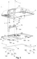
- the toilet device 1 of the first aspect of the present invention comprises coupling means including a kinematic chain configured to couple the toilet device 1 to a toilet bowl 2, wherein the kinematic chain comprises a pivotable coupling lever 5 and an actuator 6 configured and arranged to act on said pivotable coupling lever 5 to pivot the same about a pivot axis A (see Figure 2 ) between several angular coupling positions, wherein the pivotable coupling lever 5 has at least one first end portion 5a arranged opposite to a contact surface S1 of the toilet device 1 to trap, between said at least one first end portion 5a and said contact surface S1, a wall portion W1 of said toilet bowl 2 pressing against two opposed outer surfaces W1a, W1b of said wall portion W1 (see Figures 5A to 5C and 6A to 6C ), at least when at one of said several angular positions.
- the kinematic chain comprises a pivotable coupling lever 5 and an actuator 6 configured and arranged to act on said pivotable coupling lever 5 to pivot the same about a pivot
- the pivotable coupling lever 5 is a bend rod having two free front ends, each constituting a respective first end portion 5a, with an optional protection cap 5a2 (such as a rubber cap) covering an end 5a1 of each end portion 5a, a back portion 5b, and two intermediate portions 5c.
- an optional protection cap 5a2 such as a rubber cap
- the toilet device 1 comprises a housing H including a base B which comprises an articulation Ba at which the pivoting coupling lever 5 is hinged to pivot about the pivot axis A (see Figure 2 ), so that the pivoting coupling lever 5 remains, when the toilet device 1 is coupled to the toilet bowl 2, concealed within an opening 2a (see Figure 4 ) of the toilet bowl 2 for all its several angular positions.
- the articulation Ba is provided by pivotally fixing the two intermediate portions 5c of the lever 5 to projections Ba2 extending for the lower face of the base B, said fixation being provided with fasteners Ba1 and allowing the rotation of the intermediate portions 5c, and thus of the entire coupling lever 5, about pivot axis A.
- the toilet device 1 comprises a further contact surface S2 to contact a further wall portion W2 of the toilet bowl 2, and the actuator 6 is further configured and arranged to couple said further contact surface S2 to the further wall portion W2 of the toilet bowl 2 once the pivotable coupling lever 5 has been pivoted to at least one of the several angular positions.
- the contact surface S1 and further contact surface S2 are defined at an outer face of base B, particularly at a lower outer face, for the illustrated embodiments.
- the wall portion W1 is located at a front region of the contour of the opening 2a, and the further wall portion W2 at a back region thereof, although other locations are possible, for non-illustrated embodiments.
- the actuator 6 comprises a member 6a and two coupling elements 6b.
- member 6a has an inverted U-shape formed by two symmetric respective L-shaped portions, each including a first portion 6a1, to be accessed by a user, and a second portion 6a2.
- the base B has two through openings O1 each being traversed by a respective second portion 6a2 which is movable in a guided manner therethrough transversally to the pivotable coupling lever 5 to push the same by its second ends 5b thereof to pivot the pivotable coupling lever 5 about the pivot axis A between the several angular positions.
- the actuator 6 further comprises two coupling elements 6b attached to the first portions 6a1, in this case traversing a through opening thereof, a first end 6b1 of each coupling element 6b being able to be inserted into a respective hole O2 (see Figure 2 ) of the further contact surface S2 of the toilet device 1, and each coupling element 6b being configured and arranged to be accessed by a user by a second end 6b2, opposite to the first end 6b1, to longitudinally push the same to introduce further coupling elements 6b into the holes O2 up to a desired position, and thus move the member 6a to introduce its second portions 6a2 through the through openings O1 (see Figure 3 ) of the base B.
- the first ends 6b1 are configured to also be inserted into respective holes O3 (see Figures 4 , 5A , and 6A ) of the further wall portion W2 of the toilet bowl 2, and has a coupling configuration to be coupled to the further wall portion W2 of the toilet bowl 2 at the desired position.
- the coupling elements 6b are screws 6b to be screwed by the user into the holes O3 of the further wall portion W2 of the toilet bowl 2, the above mentioned coupling configuration being a threaded profile of the screws 6b which cooperates with respective threaded profiles inside the hole O3 to retain the screws 6b into the desired position, the holes O3 of the further wall portion W2 and the holes O2 of the further contact surface S2 being axially coaligned.
- the threaded profiles inside the holes O3 are defined in the inner contour of an anchor plug 8 fit thereinto.
- an anchor plug without a threaded profile can be used, such as an expansion anchor plug.
- the contact surface S1 and the hole O2 of the further contact surface S2 are located at or near respective opposite ends of the base B, as seen in Figure 2 .
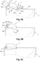
- FIGS 5A, 5B, and 5C schematically show a sequence of the mounting process of the toilet device 1 to the toilet bowl 2, for an embodiment for which the toilet device 1 is inserted into an opening 2a of the toilet bowl 2.
- the toilet device 1 further comprises an abutment contact surface S3 transversally extending from an end of the contact surface S1, and configured and arranged to, when the wall portion W1 of the toilet bowl 2 is trapped between the first end portions 5a and the contact surface S1, firmly abut against an edge W1c at which the two opposed outer faces W1a, W1b end.
- the base B when coupled to the toilet bowl 2, is partially inserted into the opening 2a of the toilet bowl 2.
- the mounting sequence starts by introducing the first ends 5a of the pivotable coupling lever 5 into the opening 2a (see Figure 5A ), then partially introducing the base B there into, abutting the abutment contact surface S3 against the edge W1c (see Figure 5B ), and the acting on the actuator, particularly screwing the screws 6b to move down the coupling element 6a, so that its second portions 6a2 push down the second ends 5b of the pivotable coupling lever 5 and make it pivot about the pivot axis A until the wall portion W1 is firmly trapped between the contact surface S1 and the first ends 5a.
- the screws 6b are screwed to anchor plugs 8 inserted into holes O3, and thus firmly coupled to the further wall portion W2 of the toilet bowl 2, as shown in Figure 5C .
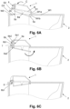
- Figures 6A, 6B, and 6C schematically show, by means of respective schematic cross-section views, a sequence of the mounting process of the toilet device 1 to the toilet bowl 2, for another embodiment for which the toilet device1 is not inserted into the opening 2a of the toilet bowl 2 but rests above the same.
- the sequence is similar to the one explained above, with the only difference that the base B, which does not have the abutment surface S3, is not inserted into the opening 2a, but, as shown in Figure 6B , rests over the upper faces of the wall portion W1 (particularly contact surface S1) and further wall portion W2 (particularly further contact surface S2), and of the rest of wall portions surrounding the contour of opening 2a.
- FIGS 7A, 7B, and 7C a sequence of the dismounting process of the cover C of the housing H of the toilet device 1 without uncoupling the base B thereof from the toilet bowl 2 is shown. Being able to disassemble the cover C without needing to disassemble the base B indeed facilitates maintenance work.
- the cover C is decoupled from the base B by unscrewing screws 7 from holes O4 (see Figure 2 ). Screws 7, and also screws 6b, are accessed by a user through an opening Co (see Figure 7A ) defined in the back of the cover C.
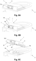
- FIGs 8A, 8B, and 8C a sequence of the dismounting process of the toilet device 1 from the toilet bowl 2 is shown.
- the entire toilet device 1 is decoupled from the toilet bowl 2. This is done by unscrewing screws 6b from further wall portion W2, specifically from anchor plugs 8 for the embodiments shown in Figures 5C and 6C .
- FIGs 9 and 10 a further embodiment of the toilet device 1 and of the toilet 3 of the present invention is shown, where the toilet device 1 (shown in a pre-coupling position in Figure 9 and coupled to the toilet bowl in Figure 10 ) also comprises a toilet seat 9 and a cover 10 assembly , and the toilet bowl 2 is adapted to operate as a bidet, particularly by providing a washing liquid, through a washing nozzle W which is shown in part in Figure 10 in an extended position projecting from the housing H of the toilet device 1 into the toilet bowl 2.
- toilet device 1 needed for the operation thereof (such as fluid conducts, electronic circuitry, etc.) remain housed withing housing H, and have not been shown in the appended figures for clarity's sake, not to obscure the description thereof.
Landscapes
- Health & Medical Sciences (AREA)
- Public Health (AREA)
- Molecular Biology (AREA)
- Epidemiology (AREA)
- Life Sciences & Earth Sciences (AREA)
- Engineering & Computer Science (AREA)
- Hydrology & Water Resources (AREA)
- Water Supply & Treatment (AREA)
- Toilet Supplies (AREA)
- Bidet-Like Cleaning Device And Other Flush Toilet Accessories (AREA)
Claims (15)
- Toilettenvorrichtung (1), die mit einer Toilettenschüssel (2) zu koppeln ist, umfassend Kopplungsmittel einschließlich einer kinematischen Kette, die konfiguriert ist, die Toilettenvorrichtung (1) mit der Toilettenschüssel (2) zu koppeln,wobei die kinematische Kette einen schwenkbaren Kopplungshebel (5) und einen Aktuator (6), der so konfiguriert und angeordnet ist, um auf den schwenkbaren Kopplungshebel (5) einzuwirken, um diesen um eine Schwenkachse (A) zwischen mehreren Winkelkopplungspositionen zu schwenken, umfasst,dadurch gekennzeichnet, dassder schwenkbare Kopplungshebel (5) wenigstens einen ersten Endabschnitt (5a) aufweist, der gegenüber einer Kontaktfläche (S1) der Toilettenvorrichtung (1) angeordnet ist, um zwischen dem wenigstens einen ersten Endabschnitt (5a) und der Kontaktfläche (S1) einen Wandabschnitt (W1) der Toilettenschüssel (2) einzuklemmen, durch Pressen auf zwei gegenüberliegende Außenflächen (W1a, W1b) des Wandabschnitts (W1), wenigstens dann, wenn sich dieser bei einer von mehreren Winkelpositionen befindet.
- Toilettenvorrichtung (1) nach Anspruch 1, wobei wenigstens ein Teil des schwenkbaren Kopplungshebels (5), einschließlich des wenigstens einen ersten Endabschnitts (5a), elastisch verformbar ist, um zwischen dem wenigstens einen ersten Endabschnitt (5a) und der Kontaktfläche (S1) einen von mehreren Toilettenschüssel-Wandabschnitten (W1), die unterschiedliche Dicken aufweisen, für dieselbe der mehreren Winkelpositionen einzuklemmen.
- Toilettenvorrichtung (1) nach einem der Ansprüche 1 bis 2, wobei die Toilettenvorrichtung (1) eine weitere Kontaktfläche (S2) umfasst, um einen weiteren Wandabschnitt (W2) der Toilettenschüssel (2) zu kontaktieren, und wobei der Aktuator (6) ferner so konfiguriert und angeordnet ist, um die weitere Kontaktfläche (S2) mit dem weiteren Wandabschnitt (W2) der Toilettenschüssel (2) zu koppeln, sobald der schwenkbare Kopplungshebel (5) in wenigstens eine von mehreren Winkelpositionen geschwenkt worden ist.
- Toilettenvorrichtung (1) nach einem der vorhergehenden Ansprüche, wobei die Toilettenvorrichtung (1) ein Gehäuse (H) einschließlich einer Basis (B) umfasst, wobei die Basis (B) ein Gelenk (Ba) aufweist, an dem der schwenkbare Kopplungshebel (5) so angelenkt ist, um die Schwenkachse (A) zu schwenken, so dass der schwenkbare Kopplungshebel (5) dann, wenn die Toilettenvorrichtung (1) mit der Toilettenschüssel (2) gekoppelt ist, innerhalb einer Öffnung (2a) der Toilettenschüssel (2) für alle der mehreren Winkelpositionen verbleibt.
- Toilettenvorrichtung (1) nach Anspruch 4, wenn abhängig von Anspruch 3, wobei die Kontaktfläche (S1) und/oder die weitere Kontaktfläche (S2) an einer Außenfläche der Basis (B) definiert ist/sind.
- Toilettenvorrichtung (1) nach einem der Ansprüche 4 oder 5, wobei der Aktuator (6) wenigstens ein Element (6a) umfasst, das eine Durchgangsöffnung (O1) der Basis (B) durchquert und in geführter Weise transversal dort hindurch zum schwenkbaren Kopplungshebel (5) bewegbar ist, um diesen durch ein zweites Ende (5b) davon zu schieben, um den schwenkbaren Kopplungshebel (5) zwischen den mehreren Winkelpositionen um die Schwenkachse (A) zu schwenken, wobei das wenigstens eine Element (6a) einen ersten Abschnitt (6a1) aufweist, der für einen Benutzer zugänglich ist.
- Toilettenvorrichtung (1) nach Anspruch 6, wenn abhängig von Anspruch 3, wobei der Aktuator (6) ferner wenigstens ein Kopplungselement (6b) umfasst, das an dem ersten Abschnitt (6a1) des wenigstens einen Elements (6a) befestigt ist, wobei wenigstens ein erstes Ende (6b1) des wenigstens einen Kopplungselements (6b) in der Lage ist, in ein Loch (O2) der weiteren Kontaktfläche (S2) der Toilettenvorrichtung (1) eingesetzt zu werden, und wobei das wenigstens eine Kopplungselement (6b) so konfiguriert und angeordnet ist, dass es durch ein zweites Ende (6b2) gegenüber dem ersten Ende (6b1) für einen Benutzer zugänglich ist, um dieses in Längsrichtung zu schieben, um das wenigstens eine Kopplungselement (6b) weiter bis zu einer gewünschten Position in das Loch (O2) einzuführen, und somit das wenigstens eine Element (6a) durch die Durchgangsöffnung (O1) der Basis (B) zu bewegen.
- Toilettenvorrichtung (1) nach Anspruch 7, wobei das erste Ende (6b1) des wenigstens einen Kopplungselements (6b) so konfiguriert ist, auch in ein Loch (O3) des weiteren Wandabschnitts (W2) der Toilettenschüssel (2) eingesetzt zu werden, und eine Kopplungskonfiguration aufweist, um mit dem weiteren Wandabschnitt (W2) der Toilettenschüssel (2) bei der gewünschten Position gekoppelt zu werden.
- Toilettenvorrichtung (1) nach Anspruch 8, wobei das wenigstens eine Kopplungselement (6b) eine Schraube (6b) ist, die durch den Benutzer in das Loch (O3) des weiteren Wandabschnitts (W2) der Toilettenschüssel (2) zu schrauben ist, wobei die Kopplungskonfiguration ein Gewindeprofil der wenigstens einen Schraube (6b) ist, das mit einem entsprechenden Gewindeprofil im Inneren des Lochs (O3) zusammenwirkt, um die wenigstens eine Schraube (6b) in der gewünschten Position zu halten, wobei das Loch (O3) des weiteren Wandabschnitts (W2) und das Loch (O2) der weiteren Kontaktfläche (S2) axial aufeinander ausgerichtet sind.
- Toilettenvorrichtung (1) nach einem der Ansprüche 7 bis 9, wobei sich die Kontaktfläche (S1) und das Loch (O2) der weiteren Kontaktfläche (S2) an oder nahe der jeweils gegenüberliegenden Enden der Basis (B) befinden.
- Toilettenvorrichtung (1) nach einem der Ansprüche 4 bis 10, wobei das Gehäuse (H) ferner eine Abdeckung (10) umfasst, die lösbar an der Basis (B) mittels Befestigungsmitteln (7), die einem Benutzer zugänglich sind, befestigt ist, um die Abdeckung (C) an der Basis (B) zu befestigen bzw. von dieser zu lösen, wobei es nicht erforderlich ist, dass die Basis (B) von der Toilettenschüssel (2) entkoppelt wird.
- Toilettenvorrichtung (1) nach Anspruch 11, wobei die Abdeckung (C) des Gehäuses (H) eine Schwenkachse für eine Toilettensitz (9)-Abdeckungs (10)-Anordnung aufweist.
- Toilette (3), umfassend:- eine Toilettenschüssel (2), die einen Wandabschnitt (W1) umfasst; und- die Toilettenvorrichtung (1) nach einem der vorhergehenden Ansprüche, die mit der Toilettenschüssel (2) gekoppelt ist, indem zwischen dem wenigstens einen ersten Endabschnitt (5a) des schwenkbaren Kopplungshebels (5) und der Kontaktfläche (S1) mit der Toilettenvorrichtung (1) der Wandabschnitt (W1) eingeklemmt wird, durch Pressen auf zwei gegenüberliegende Außenflächen (W1a, W1b) des Wandabschnitts (W1), wenigstens dann, wenn sich dieser bei einer der mehreren Winkelkopplungspositionen befindet.
- Toilette (3) nach Anspruch 13, wobei die Toilettenvorrichtung (1) nach einem der Ansprüche 7 bis 9 definiert ist, wenn abhängig von Anspruch 3, und wobei die Toilettenschüssel (2) eine Öffnung (2a) und einen weiteren Wandabschnitt (W2) umfasst, und wobei der Wandabschnitt (W1) und der weitere Wandabschnitt (W2) unterschiedliche Bereiche der Öffnung (2a) der Toilettenschüssel (2) teilweise abgrenzen und umgeben, wobei die Toilettenvorrichtung (1) mit der Toilettenschüssel (2) außerdem durch das wenigstens eine Kopplungselement (6b) des Aktuators (6) gekoppelt ist, der die weitere Kontaktfläche (S2) der Toilettenvorrichtung (1) mit dem weiteren Wandabschnitt (W2) koppelt, sobald der schwenkbare Kopplungshebel (5) in wenigstens eine von den mehreren Winkelpositionen geschwenkt worden ist.
- Toilette (3) nach einem der Ansprüche 13 bis 14, wobei die Toilettenvorrichtung (1) eine Waschvorrichtung für eine Toilette ist, die so ausgelegt ist, um als ein Bidet verwendet zu werden, wobei die Waschvorrichtung eine Wasserabgabedüse (W) zum analen und/oder perinealen Waschen umfasst, die wenigstens teilweise im Gehäuse (H) montiert ist.
Priority Applications (2)
| Application Number | Priority Date | Filing Date | Title |
|---|---|---|---|
| ES22383140T ES3037413T3 (en) | 2022-11-28 | 2022-11-28 | Toilet device to be coupled to a toilet bowl, and toilet comprising the toilet device |
| EP22383140.5A EP4375433B1 (de) | 2022-11-28 | 2022-11-28 | Toilettenvorrichtung zur kopplung an eine toilettenschüssel und toilette mit der toilettenvorrichtung |
Applications Claiming Priority (1)
| Application Number | Priority Date | Filing Date | Title |
|---|---|---|---|
| EP22383140.5A EP4375433B1 (de) | 2022-11-28 | 2022-11-28 | Toilettenvorrichtung zur kopplung an eine toilettenschüssel und toilette mit der toilettenvorrichtung |
Publications (3)
| Publication Number | Publication Date |
|---|---|
| EP4375433A1 EP4375433A1 (de) | 2024-05-29 |
| EP4375433B1 true EP4375433B1 (de) | 2025-06-18 |
| EP4375433C0 EP4375433C0 (de) | 2025-06-18 |
Family
ID=84421571
Family Applications (1)
| Application Number | Title | Priority Date | Filing Date |
|---|---|---|---|
| EP22383140.5A Active EP4375433B1 (de) | 2022-11-28 | 2022-11-28 | Toilettenvorrichtung zur kopplung an eine toilettenschüssel und toilette mit der toilettenvorrichtung |
Country Status (2)
| Country | Link |
|---|---|
| EP (1) | EP4375433B1 (de) |
| ES (1) | ES3037413T3 (de) |
Family Cites Families (4)
| Publication number | Priority date | Publication date | Assignee | Title |
|---|---|---|---|---|
| US2705495A (en) * | 1953-10-05 | 1955-04-05 | Vrana Mary | Fountain syringe |
| JPS539535B2 (de) | 1972-04-12 | 1978-04-06 | ||
| SE439878B (sv) * | 1984-03-30 | 1985-07-08 | Ledin Bonevik Birgitta Barbro | Anordning avsedd att anbringas pa en toalettstol for att medge tarmskoljning |
| US8382047B1 (en) * | 2009-02-12 | 2013-02-26 | Shawn Eric Hildebrand | Multi-use clamping device |
-
2022
- 2022-11-28 ES ES22383140T patent/ES3037413T3/es active Active
- 2022-11-28 EP EP22383140.5A patent/EP4375433B1/de active Active
Also Published As
| Publication number | Publication date |
|---|---|
| EP4375433A1 (de) | 2024-05-29 |
| ES3037413T3 (en) | 2025-10-01 |
| EP4375433C0 (de) | 2025-06-18 |
Similar Documents
| Publication | Publication Date | Title |
|---|---|---|
| KR101485374B1 (ko) | 위생 설비용 편심힌지 | |
| AU781124B2 (en) | A window operator | |
| US6571407B1 (en) | Faucet retainers | |
| US5593193A (en) | Thumb actuated latch retracting mechanism for grip handle locks including integral installation gripping aid | |
| EP4375433A1 (de) | Toilettenvorrichtung zur kopplung an eine toilettenschüssel und toilette mit der toilettenvorrichtung | |
| EP1744411A3 (de) | Elektrische Verbinderanordnung | |
| CA2111132A1 (en) | Means for securing a cover over a drainage channel | |
| JP4224750B2 (ja) | 調整蝶番 | |
| CN113133710B (zh) | 用于在马桶本体上能松开地安装配件的安装装置 | |
| US6557959B1 (en) | Cabinet door hinge with strain relief structure | |
| PL179640B1 (pl) | Urzadzenie uruchamiajace do armatury odplywowej zbiornika spluczki PL PL PL | |
| RU2350729C2 (ru) | Фурнитура для раздвижной створки и система фурнитуры | |
| JP4287128B2 (ja) | 排水栓装置 | |
| JP3653692B2 (ja) | 補強部材 | |
| JP3646230B2 (ja) | 蝶番 | |
| JP4179656B2 (ja) | 長尺体支持具 | |
| KR200240359Y1 (ko) | 좌변기 커버의 고정장치 | |
| KR200187449Y1 (ko) | 가구용 힌지 조립체 | |
| KR200241062Y1 (ko) | 세면기의 팝업밸브 | |
| KR100434155B1 (ko) | 이중문틀 좌우양측 개폐문 고정장치 | |
| JP2689091B2 (ja) | 蝶 番 | |
| JPH0737594Y2 (ja) | 便座の取付構造 | |
| GB2289902A (en) | Resilient mounting means for securing a cover and/or seat to a W.C. | |
| KR200319702Y1 (ko) | 양변기의 물내림 레버장치 | |
| EP0955437A3 (de) | Befestigungsvorrichtung und Verfahren mit einem Ring für Paneele |
Legal Events
| Date | Code | Title | Description |
|---|---|---|---|
| PUAI | Public reference made under article 153(3) epc to a published international application that has entered the european phase |
Free format text: ORIGINAL CODE: 0009012 |
|
| STAA | Information on the status of an ep patent application or granted ep patent |
Free format text: STATUS: THE APPLICATION HAS BEEN PUBLISHED |
|
| AK | Designated contracting states |
Kind code of ref document: A1 Designated state(s): AL AT BE BG CH CY CZ DE DK EE ES FI FR GB GR HR HU IE IS IT LI LT LU LV MC ME MK MT NL NO PL PT RO RS SE SI SK SM TR |
|
| STAA | Information on the status of an ep patent application or granted ep patent |
Free format text: STATUS: REQUEST FOR EXAMINATION WAS MADE |
|
| 17P | Request for examination filed |
Effective date: 20241008 |
|
| RBV | Designated contracting states (corrected) |
Designated state(s): AL AT BE BG CH CY CZ DE DK EE ES FI FR GB GR HR HU IE IS IT LI LT LU LV MC ME MK MT NL NO PL PT RO RS SE SI SK SM TR |
|
| GRAP | Despatch of communication of intention to grant a patent |
Free format text: ORIGINAL CODE: EPIDOSNIGR1 |
|
| STAA | Information on the status of an ep patent application or granted ep patent |
Free format text: STATUS: GRANT OF PATENT IS INTENDED |
|
| INTG | Intention to grant announced |
Effective date: 20250210 |
|
| GRAS | Grant fee paid |
Free format text: ORIGINAL CODE: EPIDOSNIGR3 |
|
| GRAA | (expected) grant |
Free format text: ORIGINAL CODE: 0009210 |
|
| STAA | Information on the status of an ep patent application or granted ep patent |
Free format text: STATUS: THE PATENT HAS BEEN GRANTED |
|
| AK | Designated contracting states |
Kind code of ref document: B1 Designated state(s): AL AT BE BG CH CY CZ DE DK EE ES FI FR GB GR HR HU IE IS IT LI LT LU LV MC ME MK MT NL NO PL PT RO RS SE SI SK SM TR |
|
| REG | Reference to a national code |
Ref country code: GB Ref legal event code: FG4D |
|
| REG | Reference to a national code |
Ref country code: CH Ref legal event code: EP |
|
| REG | Reference to a national code |
Ref country code: DE Ref legal event code: R096 Ref document number: 602022016071 Country of ref document: DE |
|
| REG | Reference to a national code |
Ref country code: CH Ref legal event code: EP |
|
| REG | Reference to a national code |
Ref country code: IE Ref legal event code: FG4D |
|
| U01 | Request for unitary effect filed |
Effective date: 20250714 |
|
| U07 | Unitary effect registered |
Designated state(s): AT BE BG DE DK EE FI FR IT LT LU LV MT NL PT RO SE SI Effective date: 20250718 |
|
| REG | Reference to a national code |
Ref country code: ES Ref legal event code: FG2A Ref document number: 3037413 Country of ref document: ES Kind code of ref document: T3 Effective date: 20251001 |
|
| PG25 | Lapsed in a contracting state [announced via postgrant information from national office to epo] |
Ref country code: NO Free format text: LAPSE BECAUSE OF FAILURE TO SUBMIT A TRANSLATION OF THE DESCRIPTION OR TO PAY THE FEE WITHIN THE PRESCRIBED TIME-LIMIT Effective date: 20250918 Ref country code: GR Free format text: LAPSE BECAUSE OF FAILURE TO SUBMIT A TRANSLATION OF THE DESCRIPTION OR TO PAY THE FEE WITHIN THE PRESCRIBED TIME-LIMIT Effective date: 20250919 |
|
| PG25 | Lapsed in a contracting state [announced via postgrant information from national office to epo] |
Ref country code: HR Free format text: LAPSE BECAUSE OF FAILURE TO SUBMIT A TRANSLATION OF THE DESCRIPTION OR TO PAY THE FEE WITHIN THE PRESCRIBED TIME-LIMIT Effective date: 20250618 |
|
| PG25 | Lapsed in a contracting state [announced via postgrant information from national office to epo] |
Ref country code: RS Free format text: LAPSE BECAUSE OF FAILURE TO SUBMIT A TRANSLATION OF THE DESCRIPTION OR TO PAY THE FEE WITHIN THE PRESCRIBED TIME-LIMIT Effective date: 20250918 |
|
| U20 | Renewal fee for the european patent with unitary effect paid |
Year of fee payment: 4 Effective date: 20250926 |
|
| REG | Reference to a national code |
Ref country code: CH Ref legal event code: U11 Free format text: ST27 STATUS EVENT CODE: U-0-0-U10-U11 (AS PROVIDED BY THE NATIONAL OFFICE) Effective date: 20251201 |
|
| PG25 | Lapsed in a contracting state [announced via postgrant information from national office to epo] |
Ref country code: IS Free format text: LAPSE BECAUSE OF FAILURE TO SUBMIT A TRANSLATION OF THE DESCRIPTION OR TO PAY THE FEE WITHIN THE PRESCRIBED TIME-LIMIT Effective date: 20251018 |
|
| PG25 | Lapsed in a contracting state [announced via postgrant information from national office to epo] |
Ref country code: SM Free format text: LAPSE BECAUSE OF FAILURE TO SUBMIT A TRANSLATION OF THE DESCRIPTION OR TO PAY THE FEE WITHIN THE PRESCRIBED TIME-LIMIT Effective date: 20250618 |
|
| PGFP | Annual fee paid to national office [announced via postgrant information from national office to epo] |
Ref country code: CH Payment date: 20251201 Year of fee payment: 4 |
|
| PG25 | Lapsed in a contracting state [announced via postgrant information from national office to epo] |
Ref country code: CZ Free format text: LAPSE BECAUSE OF FAILURE TO SUBMIT A TRANSLATION OF THE DESCRIPTION OR TO PAY THE FEE WITHIN THE PRESCRIBED TIME-LIMIT Effective date: 20250618 |
|
| PG25 | Lapsed in a contracting state [announced via postgrant information from national office to epo] |
Ref country code: PL Free format text: LAPSE BECAUSE OF FAILURE TO SUBMIT A TRANSLATION OF THE DESCRIPTION OR TO PAY THE FEE WITHIN THE PRESCRIBED TIME-LIMIT Effective date: 20250618 |
|
| PG25 | Lapsed in a contracting state [announced via postgrant information from national office to epo] |
Ref country code: SK Free format text: LAPSE BECAUSE OF FAILURE TO SUBMIT A TRANSLATION OF THE DESCRIPTION OR TO PAY THE FEE WITHIN THE PRESCRIBED TIME-LIMIT Effective date: 20250618 |
|
| PGFP | Annual fee paid to national office [announced via postgrant information from national office to epo] |
Ref country code: ES Payment date: 20251201 Year of fee payment: 4 |
|
| PLBE | No opposition filed within time limit |
Free format text: ORIGINAL CODE: 0009261 |
|
| STAA | Information on the status of an ep patent application or granted ep patent |
Free format text: STATUS: NO OPPOSITION FILED WITHIN TIME LIMIT |
|
| REG | Reference to a national code |
Ref country code: CH Ref legal event code: L10 Free format text: ST27 STATUS EVENT CODE: U-0-0-L10-L00 (AS PROVIDED BY THE NATIONAL OFFICE) Effective date: 20260430 |