EP4375458A1 - Procédé de détermination d'une position d'une coulisseau d'un entraînement de porte, dispositif d'arrêt et entraînement de porte - Google Patents
Procédé de détermination d'une position d'une coulisseau d'un entraînement de porte, dispositif d'arrêt et entraînement de porte Download PDFInfo
- Publication number
- EP4375458A1 EP4375458A1 EP23201232.8A EP23201232A EP4375458A1 EP 4375458 A1 EP4375458 A1 EP 4375458A1 EP 23201232 A EP23201232 A EP 23201232A EP 4375458 A1 EP4375458 A1 EP 4375458A1
- Authority
- EP
- European Patent Office
- Prior art keywords
- sliding block
- locking
- current
- locking element
- magnetic coil
- Prior art date
- Legal status (The legal status is an assumption and is not a legal conclusion. Google has not performed a legal analysis and makes no representation as to the accuracy of the status listed.)
- Granted
Links
Images


Classifications
-
- E—FIXED CONSTRUCTIONS
- E05—LOCKS; KEYS; WINDOW OR DOOR FITTINGS; SAFES
- E05C—BOLTS OR FASTENING DEVICES FOR WINGS, SPECIALLY FOR DOORS OR WINDOWS
- E05C17/00—Devices for holding wings open; Devices for limiting opening of wings or for holding wings open by a movable member extending between frame and wing; Braking devices, stops or buffers, combined therewith
- E05C17/02—Devices for holding wings open; Devices for limiting opening of wings or for holding wings open by a movable member extending between frame and wing; Braking devices, stops or buffers, combined therewith by mechanical means
- E05C17/04—Devices for holding wings open; Devices for limiting opening of wings or for holding wings open by a movable member extending between frame and wing; Braking devices, stops or buffers, combined therewith by mechanical means with a movable bar or equivalent member extending between frame and wing
- E05C17/12—Devices for holding wings open; Devices for limiting opening of wings or for holding wings open by a movable member extending between frame and wing; Braking devices, stops or buffers, combined therewith by mechanical means with a movable bar or equivalent member extending between frame and wing consisting of a single rod
- E05C17/24—Devices for holding wings open; Devices for limiting opening of wings or for holding wings open by a movable member extending between frame and wing; Braking devices, stops or buffers, combined therewith by mechanical means with a movable bar or equivalent member extending between frame and wing consisting of a single rod pivoted at one end, and with the other end running along a guide member
- E05C17/28—Devices for holding wings open; Devices for limiting opening of wings or for holding wings open by a movable member extending between frame and wing; Braking devices, stops or buffers, combined therewith by mechanical means with a movable bar or equivalent member extending between frame and wing consisting of a single rod pivoted at one end, and with the other end running along a guide member with braking, clamping or securing means at the connection to the guide member
-
- E—FIXED CONSTRUCTIONS
- E05—LOCKS; KEYS; WINDOW OR DOOR FITTINGS; SAFES
- E05B—LOCKS; ACCESSORIES THEREFOR; HANDCUFFS
- E05B47/00—Operating or controlling locks or other fastening devices by electric or magnetic means
- E05B47/0001—Operating or controlling locks or other fastening devices by electric or magnetic means with electric actuators; Constructional features thereof
- E05B47/0002—Operating or controlling locks or other fastening devices by electric or magnetic means with electric actuators; Constructional features thereof with electromagnets
- E05B47/0003—Operating or controlling locks or other fastening devices by electric or magnetic means with electric actuators; Constructional features thereof with electromagnets having a movable core
-
- E—FIXED CONSTRUCTIONS
- E05—LOCKS; KEYS; WINDOW OR DOOR FITTINGS; SAFES
- E05F—DEVICES FOR MOVING WINGS INTO OPEN OR CLOSED POSITION; CHECKS FOR WINGS; WING FITTINGS NOT OTHERWISE PROVIDED FOR, CONCERNED WITH THE FUNCTIONING OF THE WING
- E05F3/00—Closers or openers with braking devices, e.g. checks; Construction of pneumatic or liquid braking devices
- E05F3/22—Additional arrangements for closers, e.g. for holding the wing in opened or other position
- E05F3/221—Mechanical power-locks, e.g. for holding the wing open or for free-moving zones
- E05F3/222—Mechanical power-locks, e.g. for holding the wing open or for free-moving zones electrically operated
-
- E—FIXED CONSTRUCTIONS
- E05—LOCKS; KEYS; WINDOW OR DOOR FITTINGS; SAFES
- E05B—LOCKS; ACCESSORIES THEREFOR; HANDCUFFS
- E05B47/00—Operating or controlling locks or other fastening devices by electric or magnetic means
- E05B2047/0048—Circuits, feeding, monitoring
- E05B2047/0067—Monitoring
-
- E—FIXED CONSTRUCTIONS
- E05—LOCKS; KEYS; WINDOW OR DOOR FITTINGS; SAFES
- E05Y—INDEXING SCHEME ASSOCIATED WITH SUBCLASSES E05D AND E05F, RELATING TO CONSTRUCTION ELEMENTS, ELECTRIC CONTROL, POWER SUPPLY, POWER SIGNAL OR TRANSMISSION, USER INTERFACES, MOUNTING OR COUPLING, DETAILS, ACCESSORIES, AUXILIARY OPERATIONS NOT OTHERWISE PROVIDED FOR, APPLICATION THEREOF
- E05Y2201/00—Constructional elements; Accessories therefor
- E05Y2201/40—Motors; Magnets; Springs; Weights; Accessories therefor
- E05Y2201/46—Magnets
- E05Y2201/462—Electromagnets
-
- E—FIXED CONSTRUCTIONS
- E05—LOCKS; KEYS; WINDOW OR DOOR FITTINGS; SAFES
- E05Y—INDEXING SCHEME ASSOCIATED WITH SUBCLASSES E05D AND E05F, RELATING TO CONSTRUCTION ELEMENTS, ELECTRIC CONTROL, POWER SUPPLY, POWER SIGNAL OR TRANSMISSION, USER INTERFACES, MOUNTING OR COUPLING, DETAILS, ACCESSORIES, AUXILIARY OPERATIONS NOT OTHERWISE PROVIDED FOR, APPLICATION THEREOF
- E05Y2201/00—Constructional elements; Accessories therefor
- E05Y2201/60—Suspension or transmission members; Accessories therefor
- E05Y2201/622—Suspension or transmission members elements
- E05Y2201/624—Arms
-
- E—FIXED CONSTRUCTIONS
- E05—LOCKS; KEYS; WINDOW OR DOOR FITTINGS; SAFES
- E05Y—INDEXING SCHEME ASSOCIATED WITH SUBCLASSES E05D AND E05F, RELATING TO CONSTRUCTION ELEMENTS, ELECTRIC CONTROL, POWER SUPPLY, POWER SIGNAL OR TRANSMISSION, USER INTERFACES, MOUNTING OR COUPLING, DETAILS, ACCESSORIES, AUXILIARY OPERATIONS NOT OTHERWISE PROVIDED FOR, APPLICATION THEREOF
- E05Y2400/00—Electronic control; Electrical power; Power supply; Power or signal transmission; User interfaces
- E05Y2400/10—Electronic control
- E05Y2400/20—Electronic control of brakes, disengaging means, holders or stops
-
- E—FIXED CONSTRUCTIONS
- E05—LOCKS; KEYS; WINDOW OR DOOR FITTINGS; SAFES
- E05Y—INDEXING SCHEME ASSOCIATED WITH SUBCLASSES E05D AND E05F, RELATING TO CONSTRUCTION ELEMENTS, ELECTRIC CONTROL, POWER SUPPLY, POWER SIGNAL OR TRANSMISSION, USER INTERFACES, MOUNTING OR COUPLING, DETAILS, ACCESSORIES, AUXILIARY OPERATIONS NOT OTHERWISE PROVIDED FOR, APPLICATION THEREOF
- E05Y2400/00—Electronic control; Electrical power; Power supply; Power or signal transmission; User interfaces
- E05Y2400/10—Electronic control
- E05Y2400/44—Sensors not directly associated with the wing movement
-
- E—FIXED CONSTRUCTIONS
- E05—LOCKS; KEYS; WINDOW OR DOOR FITTINGS; SAFES
- E05Y—INDEXING SCHEME ASSOCIATED WITH SUBCLASSES E05D AND E05F, RELATING TO CONSTRUCTION ELEMENTS, ELECTRIC CONTROL, POWER SUPPLY, POWER SIGNAL OR TRANSMISSION, USER INTERFACES, MOUNTING OR COUPLING, DETAILS, ACCESSORIES, AUXILIARY OPERATIONS NOT OTHERWISE PROVIDED FOR, APPLICATION THEREOF
- E05Y2400/00—Electronic control; Electrical power; Power supply; Power or signal transmission; User interfaces
- E05Y2400/10—Electronic control
- E05Y2400/44—Sensors not directly associated with the wing movement
- E05Y2400/445—Switches
-
- E—FIXED CONSTRUCTIONS
- E05—LOCKS; KEYS; WINDOW OR DOOR FITTINGS; SAFES
- E05Y—INDEXING SCHEME ASSOCIATED WITH SUBCLASSES E05D AND E05F, RELATING TO CONSTRUCTION ELEMENTS, ELECTRIC CONTROL, POWER SUPPLY, POWER SIGNAL OR TRANSMISSION, USER INTERFACES, MOUNTING OR COUPLING, DETAILS, ACCESSORIES, AUXILIARY OPERATIONS NOT OTHERWISE PROVIDED FOR, APPLICATION THEREOF
- E05Y2900/00—Application of doors, windows, wings or fittings thereof
- E05Y2900/10—Application of doors, windows, wings or fittings thereof for buildings or parts thereof
- E05Y2900/13—Type of wing
- E05Y2900/132—Doors
Definitions
- the invention relates to a method for determining a position of a sliding block of a door drive having a locking device for automatically closing a door, which sliding block is mounted so as to be movable along a slide rail between a closed position and an open position, as well as to a locking device designed to carry out this method and to a door drive equipped with such a locking device.
- the method according to the invention is provided for a locking device which comprises a locking element for locking a movement of a sliding block from the open position towards the closed position corresponding to a closing movement of the door and an energizable electromagnet.
- the locking element can be moved between a locking position in which it is designed to hinder the movement of the sliding block and a release position in which it is designed to release the movement of the sliding block.
- the electromagnet acts as an actuator and locks the locking element in the locking position when energized with a predetermined current strength.
- the locking element can be pressed by the sliding block from the locking position into the release position when the sliding block moves over the locking element;
- the present invention also relates to a locking device designed to carry out this method and to a door drive equipped with such a locking device.
- the method comprises at least the following steps: applying a current of the predetermined or lower current intensity to a magnetic coil of the electromagnet; monitoring the coil current of the electromagnet; detecting when the sliding block passes over the locking element based on the time profile of the monitored coil current; and determining the position of the sliding block in relation to the locking element, in particular whether the sliding block is in the open position or in the closed position, using the detection of when the sliding block passes over the locking element.
- the blocking element is used here as part of a first sensor device and the position or position of the sliding block in relation to the blocking element is determined using the coil current of the electromagnet coupled to the blocking element.
- the position or position of the sliding block in relation to the blocking element is determined using the coil current of the electromagnet coupled to the blocking element.
- the detection of the sliding block overrunning the blocking element is carried out by detecting the occurrence of current peaks in the monitored coil current when the sliding block overruns the blocking element.
- a movement of the locking element from the locking position to the release position is preferably detected via a current peak of a first polarity and a movement of the locking element from the release position to the locking position is preferably detected via a current peak of a second polarity opposite to the first polarity.
- the electromagnet comprises an armature which is arranged displaceably within the magnetic coil and is connected to an armature plate arranged outside the magnetic coil.
- the armature is coupled to the blocking element in such a way that the armature plate breaks away from the magnetic coil to cause the current peak of the first polarity when the blocking element moves from the locking position to the release position, and strikes the magnetic coil to cause the current peak of the second polarity when the blocking element moves from the release position to the locking position.
- the respective current peak occurs because the inductance of the magnetic coil changes abruptly when the armature plate breaks away or strikes.
- the locking device preferably comprises a separate sensor which is arranged in front of the locking element with respect to a movement of the sliding block from the closed position towards the open position.
- the separate sensor detects when the sliding block is at the height of the separate sensor.
- the position of the sliding block is determined using the order of detection when the sliding block is at the height of the separate sensor and the detection of the sliding block passing over the locking element, and thus using the direction of travel of the sliding block.
- the magnetic coil is supplied with a current of low current intensity when the sliding block approaches the locking element from the closed position in the direction of the open position, and is supplied with a current of predetermined current intensity when the sliding block approaches the locking element from the open position in the direction of the closed position.
- the low current strength ensures that when the sliding block moves from the closed position towards the open position, a movement of the locking element can be detected by means of a current peak in the coil current, without the movement of the sliding block being unnecessarily hindered due to an excessive current strength.
- the predetermined current strength locks the locking element and thus blocks the movement of the sliding block from its open position towards the closed position, as is the task of a locking device.
- the predetermined current strength serves to (at least partially) generate a holding force on the locking element intended to block the movement of the sliding block.
- the predetermined current intensity is at least 1 time, in particular at least 10 times, in particular at least 20 times, greater than the lower current intensity.
- the lower current is in the range of 1 mA to 20 mA, in particular 10 mA, and/or the predetermined current is in the range of 2 mA to 400 mA.
- a locking device for locking a sliding block of a door drive for automatically closing a door, which sliding block is mounted so as to be movable along a sliding rail between a closed position and an open position, is designed to carry out the method described above.
- a door drive according to the invention in particular a door closer according to the invention, comprises the locking device described above as well as a corresponding slide rail and a corresponding slide block.
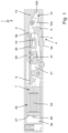
- the locking device 1 shown for locking a sliding block of a door drive for automatically closing a door, which sliding block is mounted so as to be movable along a sliding rail between a closed position and an open position, is a preferred exemplary embodiment of a locking device which is designed to carry out the method according to the invention. It comprises a housing 3, a locking element 5, an actuator 7 and a control device 9.
- the locking element 5 is movably mounted in the housing 3 via a stationary first pivot joint 6.
- the locking element 5 is movable between a locking position (in FIG. 1 shown) and a release position.
- a locking position in FIG. 1 shown
- a release position In the locking position of the locking element 5, at least one head section 5a of the locking element 5 protrudes from the housing 3 in order to hinder or block a movement of a sliding block (not shown here) along a slide rail (not shown) positioned on the locking device 1 (in particular underneath it).
- the head section 5a of the locking element 5 is retracted into the housing 3 in order not to hinder or to release a movement of the sliding block along the locking device 1.
- the locking element 5 is connected to a first coupling arm 10a of a coupling rod 10 via a second rotary joint 8 at a coupling section 5b opposite the head section 5a.
- the first coupling arm 10a is connected to a second coupling arm 10b of the coupling rod 10 via a third rotary joint 11.
- the second coupling arm 10b is rotatably mounted relative to the housing 3 via a stationary fourth rotary joint 13 and is connected to a third Coupling arm 10c of the coupling rod 10.
- the third coupling arm 10c is finally connected via a sixth swivel joint 19 to an anchor 21 which is displaceably mounted along the housing 3.
- the sixth swivel joint 19 is supported by a guide plate 20 (see FIG.
- the armature 21 is only mounted so as to be displaceable axially along the housing 3.
- the armature 21 is also mounted in the housing in such a way that it is only displaceable axially along the housing 3.
- the armature 21 is part of an electromagnet 25 and is at least partially surrounded by a magnetic coil 23 of the electromagnet 25, which is arranged inside a housing of the electromagnet 25, the electromagnet 25 forming at least part of the actuator 7.
- the electromagnet 25 functions as an actuator 7.
- the armature 21 is coupled to an armature plate 27 by means of a fixing element 26.
- the armature plate 27 is arranged outside the magnetic coil 23 and is dimensioned such that it cannot immerse itself in the magnetic coil 23, but rather strikes the magnetic coil 23 or the electromagnet 25.
- a receiving area 3a is formed in which the armature plate 27 can be moved axially along the housing 3 between a stop position in which the armature plate 27 strikes the electromagnet 25 or the magnetic coil 23 (cf. FIG. 1 ), and at least one further position in which the armature plate 27 is released from the electromagnet 25 or from the magnetic coil 23 (starting from the position shown further to the left in FIG. 1 ), which is mounted so that it can move.
- the locking device 1 comprises a pre-tensioning element (not shown) which ensures that the locking element 5 is pre-tensioned into its locking position, so that the locking element 5 always assumes the locking position when the locking element 5 is not pressed into the release position by the sliding block 33.
- the pre-tensioning element acts directly on the locking element 5 or a component of the coupling rod 10 and is designed in particular as a mechanical prestressing element, for example as a (leg) spring.
- the magnetic coil 23 is coupled to the control device 9 and can be supplied with current by it.
- the control device 9 can be coupled to a corresponding, in particular external, power supply (not shown), for example via cable 29.
- the control device 9 is designed to monitor and evaluate the current flowing through the magnetic coil 23 (here also referred to as coil current).
- the value of the determined current corresponds to a first detection signal, whereby the actuator 7 effectively functions at least as a component of a first sensor device 4 of the locking device 1.
- the control device 9 is designed to determine the position of the sliding block in relation to the locking element 5 using the detection of the crossing of the locking element 5 by the sliding block. In particular, the control device 9 can determine whether the sliding block is in the open position or in the closed position. How this happens in concrete terms is explained below with reference to FIG. 3 described.
- the locking device 1 in the embodiment shown comprises a second sensor device 31 or a separate sensor 31 which is coupled to the control device 9.
- the separate sensor 31 is connected to the control device 9 in relation to a movement of the sliding block from the closed position towards the open position (in FIG. 1 from left to right) in front of the blocking element 5. It is designed to detect whether the sliding block is at the level of the separate sensor 31 and to output a corresponding second detection signal to the control device 9.
- the separate sensor 31 is designed as an electrical switching element and specifically as a microswitch.
- other designs are also possible, such as other contact sensors or designs with contact-free sensors, such as optical sensors or magnetic sensors.
- the control device 9 is designed to receive the two detection signals, i.e. the first detection signal from the first sensor device 4, and the second detection signal from the second sensor device 31 or the separate sensor 31. Furthermore, the control device 9 is designed to use these two detection signals to determine the direction of travel of the sliding block when it passes over the locking element 5 and thus the position of the sliding block in relation to the locking element 5. In particular, the control device 9 can determine whether the sliding block is in the closed position (left in FIG. 1 ) or in the open position (right in FIG. 1 ). It is also possible for the control device 9 in the embodiment shown to determine various intermediate positions of the sliding block which are located between the closed position and the open position.
- FIG. 3 schematically five different positions are shown, which a sliding block 33 of a door drive in relation to the locking element 5 and the second sensor device 31 or the separate sensor 31 of the FIG. 1 shown locking device 1.
- the FIG. 4 shows a diagram showing a coil current during a movement of the sliding block from position 2 FIG. 3 in position 3 FIG. 3 and back to position 2 from FIG. 3 reproduces.
- position 1 which in the sense of the present invention corresponds to a closed position of the sliding block 33
- the separate sensor 31 is in an "unactuated” state and thus does not detect the positioning of the sliding block 33 at the level of the separate sensor 31.
- the locking element 5 is in its locking position due to its pre-tensioning by the pre-tensioning element.
- the control device 9 does not supply current to the magnetic coil 23.
- the separate sensor 31 is "activated” and thus detects the positioning of the sliding block 33 at the level of the separate sensor 31.
- the locking element 5 is not yet pressed into the release position by the sliding block 33.
- the control device 9 In anticipation of the sliding block 33 beginning to move over the locking element 5, the control device 9 now applies a first, relatively low current I1 of preferably 1 mA to 20 mA, for example 10 mA, to the magnetic coil 23. This is necessary in order to be able to detect a movement of the locking element 5 between its locking position and its release position in the embodiment described above, as will become clear below.
- the separate sensor 31 falls back into the "unactuated” state or the separate sensor 31 no longer detects that the sliding block 33 is at its height. This allows the control device 9 to recognize that the sliding block 33 is back in position 1, i.e. in its closed position. Due to the fact that the locking element 5 by the sliding block 33, the control device 9 stops supplying current to the magnetic coil 23.
- the sliding block 33 presses the locking element 5 against the force of the pre-tensioning element from its locking position to the release position (here upwards).
- This movement of the locking element 5 is transmitted to the armature 21 by the coupling rod 10 and leads to an axial movement of the armature 21 along the housing 3 (to the left in FIG. 1 ).
- This current peak is detected by the control device 9 due to the monitoring of the coil current, whereby the control device detects that the sliding block 33 has passed over (in particular the start of passing over) the locking element 5.
- the separate sensor 31 is still in its "actuated” state and thus indicates to the control device 9 that the sliding block 33 is still at the level of the separate sensor 31. This enables the control device 9 to determine that the sliding block 33 is in position 3.
- This position 3 corresponds to a second intermediate position of the sliding block 33 between its closed position and its open position.
- the sliding block 33 moves from here back to position 2, i.e. to the first intermediate position, the sliding block 33 releases the locking element 5 again, whereby the locking element 5 is moved back to its locking position by the pre-tensioning element or the locking element 5 takes up the locking position again.
- This movement of the locking element 5 is transmitted to the armature 21 by the coupling rod 10 and leads to an axial return movement of the armature 21 along the housing 3 (to the right in FIG. 1
- This current peak is again detected by the control device 9 due to the monitoring of the coil current.
- the separate sensor 31 is still in its "actuated” state and thus indicates to the control device 9 that the sliding block 33 is still at the level of the separate sensor 31. This enables the control device 9 to determine that the sliding block 33 is back in position 2 or back in the first intermediate position. The control device 9 thus also detects an interruption in the sliding block 33's movement over the locking element 5.
- the control device 9 determines that the sliding block 33 is in position 4 and thus in a third intermediate position.
- the control device 9 now applies a second, predetermined current intensity I2 to the magnetic coil 23, which is greater than the first current intensity I1.
- This second current intensity I2 serves to immediately generate the holding force intended to lock the locking element 5 in its locking position, i.e. to hold the sliding block 33 in the open position as soon as the sliding block 33 has passed the locking element 5 and arrives in its open position.
- the second current intensity I2 is preferably at least 1 time, in particular at least 10 times, in particular at least 20 times greater than the first current intensity I1, and is preferably in a range from 2 mA to 400 mA.
- the separate sensor 31 is "activated" again, while no further current peak is generated in the magnetic coil 23.
- the control device 9 determines that the sliding block is back in position 3 and thus in the second intermediate position.
- the control device 9 now applies the first current I1 to the magnetic coil 23 again. It is not expected that the sliding block 33 will reach the open position for the time being. Consequently, it is also not necessary to apply the second current I2 to the magnetic coil 23 of the actuator 7, which is necessary to generate the specified holding force.
- This current peak is in turn detected by the control device 9 due to the monitoring of the coil current.
- the separate sensor 31 is still in its "unactuated” state and thus indicates to the control device 9 that the sliding block 33 is no longer at the level of the separate sensor 31, i.e. in front of the locking element 5. This detects that the sliding block 33 has completed its travel over the locking element 5 from the closed position towards the open position and the control device 9 determines that the sliding block 33 is in position 5 and thus in its open position.
- the magnetic coil 23 is still energized with the second, i.e. the predetermined current intensity I2, whereby the locking element 5 is locked in its locking position with the predetermined holding force in order to prevent the sliding block 33 from moving from the open position towards the closed position (i.e. from the right back to the left into the Figures 1 and 3 ) and thus to "block" a closing movement of a door provided with the locking device. It is of course still possible to move the sliding block 33 against the predetermined holding force back towards the closed position with a corresponding amount of force, ie to manually push the locking element 5 towards the closed position. In addition to this, it is also possible to force the control device 9 in certain situations to interrupt or reverse the current supply to the magnetic coil 23 in order to release a movement of the sliding block 33 back to its closed position. Such a functionality is particularly useful as a fire protection measure.
- the sliding block 33 can be arbitrarily moved between its closed position (compare position 1 of FIG. 3 ) and its open position (compare position 5 of FIG. 3 ) can be moved back and forth.
- the sliding block 33 can be moved from its closed position (see position 1 of FIG. 3 ) only up to the third intermediate position (see position 4 in FIG. 3 ) and from here back to its closed position (see position 1 in FIG. 3 ) without changing the open position (see position 5 in FIG. 3 ).
- This is of course also analogous for a movement of the sliding block 33 from its closed position only to the second intermediate position (cf. position 3 in FIG. 3 ) or even only to the first intermediate position (see position 2 in FIG. 3 ) and back.
- the sliding block moves during a movement from the closed position (see position 1 in FIG. 3 ) into the open position (see position 5 in FIG. 3 ) or from the closed position (see position 1 in FIG. 3 ) back to the closed position (see position 1 in FIG. 3 ) the different intermediate positions (see positions 2 to 4 in FIG. 3 ) as often as desired.
- the control device 9 can thereby reliably determine the direction of travel and thus also the specific position or position of the sliding block 33.
- the control device 9 can clearly determine whether the sliding block 33 is in front of (i.e. in the Figures 1 and 3 to the left of) the locking element 5 or behind (i.e. in the Figures 1 and 3 right of) the locking element 5, and suitably control the components of the locking device 1 and/or other devices coupled to the locking device 1.
- the present invention also relates to a locking device which is designed to carry out the method according to the invention, and to a door drive (not shown), in particular a door closer which is equipped with such a locking device 1, and a corresponding slide rail (not shown) and a corresponding slide block 33.
Landscapes
- Engineering & Computer Science (AREA)
- Mechanical Engineering (AREA)
- Physics & Mathematics (AREA)
- Electromagnetism (AREA)
- Power-Operated Mechanisms For Wings (AREA)
- Lock And Its Accessories (AREA)
Priority Applications (1)
| Application Number | Priority Date | Filing Date | Title |
|---|---|---|---|
| RS20250729A RS67029B1 (sr) | 2022-11-28 | 2023-10-02 | Postupak za određivanje položaja kliznog bloka pogona za vrata, uređaj za zadržavanje i pogon za vrata |
Applications Claiming Priority (1)
| Application Number | Priority Date | Filing Date | Title |
|---|---|---|---|
| DE102022212730.7A DE102022212730A1 (de) | 2022-11-28 | 2022-11-28 | Verfahren zur Bestimmung einer Stellung eines Gleitsteins eines Türantriebs, Feststellvorrichtung und Türantrieb |
Publications (2)
| Publication Number | Publication Date |
|---|---|
| EP4375458A1 true EP4375458A1 (fr) | 2024-05-29 |
| EP4375458B1 EP4375458B1 (fr) | 2025-05-07 |
Family
ID=88241420
Family Applications (1)
| Application Number | Title | Priority Date | Filing Date |
|---|---|---|---|
| EP23201232.8A Active EP4375458B1 (fr) | 2022-11-28 | 2023-10-02 | Procédé de détermination d'une position d'un coulisseau d'un entraînement de porte, dispositif d'arrêt et entraînement de porte |
Country Status (5)
| Country | Link |
|---|---|
| EP (1) | EP4375458B1 (fr) |
| DE (1) | DE102022212730A1 (fr) |
| FI (1) | FI4375458T3 (fr) |
| PL (1) | PL4375458T3 (fr) |
| RS (1) | RS67029B1 (fr) |
Citations (5)
| Publication number | Priority date | Publication date | Assignee | Title |
|---|---|---|---|---|
| EP0321649A2 (fr) * | 1987-12-22 | 1989-06-28 | GEZE GmbH & Co. | Dispositif d'arrêt pour porte munie d'un dispositif pour fermer la porte |
| DE3844995C2 (de) * | 1987-03-05 | 2003-07-03 | Geze Gmbh | Feststellvorrichtung für eine mit einem Türschließer versehene Tür |
| WO2010052012A1 (fr) * | 2008-11-06 | 2010-05-14 | Assa Abloy Sicherheitstechnik Gmbh | Unité de blocage pour un bloque-porte, système de bloque-porte, utilisation d'une unité de blocage et procédé de blocage d'une porte |
| EP2957696A1 (fr) * | 2014-06-17 | 2015-12-23 | GEZE GmbH | Dispositif de fixation pour un battant |
| NO2434078T3 (fr) * | 2010-09-23 | 2018-03-24 |
-
2022
- 2022-11-28 DE DE102022212730.7A patent/DE102022212730A1/de active Pending
-
2023
- 2023-10-02 FI FIEP23201232.8T patent/FI4375458T3/fi active
- 2023-10-02 RS RS20250729A patent/RS67029B1/sr unknown
- 2023-10-02 EP EP23201232.8A patent/EP4375458B1/fr active Active
- 2023-10-02 PL PL23201232.8T patent/PL4375458T3/pl unknown
Patent Citations (5)
| Publication number | Priority date | Publication date | Assignee | Title |
|---|---|---|---|---|
| DE3844995C2 (de) * | 1987-03-05 | 2003-07-03 | Geze Gmbh | Feststellvorrichtung für eine mit einem Türschließer versehene Tür |
| EP0321649A2 (fr) * | 1987-12-22 | 1989-06-28 | GEZE GmbH & Co. | Dispositif d'arrêt pour porte munie d'un dispositif pour fermer la porte |
| WO2010052012A1 (fr) * | 2008-11-06 | 2010-05-14 | Assa Abloy Sicherheitstechnik Gmbh | Unité de blocage pour un bloque-porte, système de bloque-porte, utilisation d'une unité de blocage et procédé de blocage d'une porte |
| NO2434078T3 (fr) * | 2010-09-23 | 2018-03-24 | ||
| EP2957696A1 (fr) * | 2014-06-17 | 2015-12-23 | GEZE GmbH | Dispositif de fixation pour un battant |
Also Published As
| Publication number | Publication date |
|---|---|
| RS67029B1 (sr) | 2025-08-29 |
| PL4375458T3 (pl) | 2025-09-15 |
| DE102022212730A1 (de) | 2024-05-29 |
| EP4375458B1 (fr) | 2025-05-07 |
| FI4375458T3 (fi) | 2025-07-15 |
Similar Documents
| Publication | Publication Date | Title |
|---|---|---|
| EP2174046B1 (fr) | Procede de determination de la position d'un induit dans une soupape magnetique et dispositif en vue de l'actionnement d'une soupape magnetique par un induit | |
| DE3730523C2 (fr) | ||
| DE3843138C2 (fr) | ||
| DE102009018122B4 (de) | Parksperrenmechanismus und Verfahren zum Verifizieren einer Stellung eines Stößels | |
| DE10256923B4 (de) | Verfahren und Vorrichtung zur Bewegungsdämpfung von Hydraulikzylindern mobiler Arbeitsmaschinen | |
| DE3942836C2 (fr) | ||
| DE102015206729B4 (de) | Verfahren zum Steuern eines Kraftstoffeinspritz-Magnetventils und entsprechendes Motorsteuergerät | |
| EP3597891B1 (fr) | Détermination électrique des caractéristiques d'actionneurs magnétiques | |
| EP2722133A2 (fr) | Procédé de fonctionnement d'une presse manuelle à actionnement motorisé et presse manuelle | |
| WO2015165684A1 (fr) | Commutateur électrique comportant un actionneur électromagnétique | |
| DE102008056214A1 (de) | Arretiereinheit für einen Türschließer, Türschließsystem, Verwendung einer Arretiereinheit und Verfahren zum Arretieren einer Tür | |
| DE102016218635A1 (de) | Elektromechanischer Betätiger zum Betätigen einer Bremse einer Aufzugsanlage | |
| EP4375458B1 (fr) | Procédé de détermination d'une position d'un coulisseau d'un entraînement de porte, dispositif d'arrêt et entraînement de porte | |
| WO2008090047A1 (fr) | Dispositif et procédé pour la commande d'une soupape électromagnétique | |
| DE102022212731A1 (de) | Feststellvorrichtung und Türantrieb mit einer Feststellvorrichtung | |
| DE102016108778A1 (de) | Treibstoffeinspritz-Steuervorrichtung | |
| DE2554484C3 (de) | Überwachungssystem für den Lagezustand hydraulisch betätigter Armaturen | |
| DE102018207417A1 (de) | Bestimmung einer Kenngröße eines magnetischen Schaltventils | |
| DE102022207814A1 (de) | Verfahren zur Bestimmung eines Loslaufzeitpunkts eines Ankers eines Gasinjektors | |
| DE19854305A1 (de) | Verfahren und Vorrichtung zur Ansteuerung eines elektromagnetischen Verbrauchers | |
| DE102024205120B3 (de) | Verfahren zur Funktionsprüfung eines magnetischen Aktuators sowie entsprechendes System | |
| AT4844U1 (de) | Einrichtung zur mechanischen und elektrischen überprüfung der verstelleinrichtung von weichenantrieben | |
| DE102021104645A1 (de) | Verfahren zur prüfung der wiederholbarkeit der einspritzung in einen elektromagnetischen kraftstoffinjektor und entsprechender prüfstand | |
| DE102017209889B4 (de) | Schaltanordnung und Verfahren zur Bestimmung der Schaltstellung eines elektromagnetisch betätigten Schaltelements mit mehreren Schaltpositionen | |
| WO1997045309A2 (fr) | Dispositif pour la detection de ruptures dans des tringles d'essai |
Legal Events
| Date | Code | Title | Description |
|---|---|---|---|
| PUAI | Public reference made under article 153(3) epc to a published international application that has entered the european phase |
Free format text: ORIGINAL CODE: 0009012 |
|
| STAA | Information on the status of an ep patent application or granted ep patent |
Free format text: STATUS: THE APPLICATION HAS BEEN PUBLISHED |
|
| AK | Designated contracting states |
Kind code of ref document: A1 Designated state(s): AL AT BE BG CH CY CZ DE DK EE ES FI FR GB GR HR HU IE IS IT LI LT LU LV MC ME MK MT NL NO PL PT RO RS SE SI SK SM TR |
|
| STAA | Information on the status of an ep patent application or granted ep patent |
Free format text: STATUS: REQUEST FOR EXAMINATION WAS MADE |
|
| 17P | Request for examination filed |
Effective date: 20240625 |
|
| RBV | Designated contracting states (corrected) |
Designated state(s): AL AT BE BG CH CY CZ DE DK EE ES FI FR GB GR HR HU IE IS IT LI LT LU LV MC ME MK MT NL NO PL PT RO RS SE SI SK SM TR |
|
| GRAP | Despatch of communication of intention to grant a patent |
Free format text: ORIGINAL CODE: EPIDOSNIGR1 |
|
| STAA | Information on the status of an ep patent application or granted ep patent |
Free format text: STATUS: GRANT OF PATENT IS INTENDED |
|
| INTG | Intention to grant announced |
Effective date: 20250103 |
|
| P01 | Opt-out of the competence of the unified patent court (upc) registered |
Free format text: CASE NUMBER: APP_3061/2025 Effective date: 20250120 |
|
| GRAS | Grant fee paid |
Free format text: ORIGINAL CODE: EPIDOSNIGR3 |
|
| GRAA | (expected) grant |
Free format text: ORIGINAL CODE: 0009210 |
|
| STAA | Information on the status of an ep patent application or granted ep patent |
Free format text: STATUS: THE PATENT HAS BEEN GRANTED |
|
| AK | Designated contracting states |
Kind code of ref document: B1 Designated state(s): AL AT BE BG CH CY CZ DE DK EE ES FI FR GB GR HR HU IE IS IT LI LT LU LV MC ME MK MT NL NO PL PT RO RS SE SI SK SM TR |
|
| REG | Reference to a national code |
Ref country code: GB Ref legal event code: FG4D Free format text: NOT ENGLISH |
|
| REG | Reference to a national code |
Ref country code: CH Ref legal event code: EP |
|
| REG | Reference to a national code |
Ref country code: DE Ref legal event code: R096 Ref document number: 502023000958 Country of ref document: DE |
|
| REG | Reference to a national code |
Ref country code: IE Ref legal event code: FG4D Free format text: LANGUAGE OF EP DOCUMENT: GERMAN |
|
| REG | Reference to a national code |
Ref country code: FI Ref legal event code: FGE |
|
| REG | Reference to a national code |
Ref country code: NL Ref legal event code: MP Effective date: 20250507 |
|
| PG25 | Lapsed in a contracting state [announced via postgrant information from national office to epo] |
Ref country code: PT Free format text: LAPSE BECAUSE OF FAILURE TO SUBMIT A TRANSLATION OF THE DESCRIPTION OR TO PAY THE FEE WITHIN THE PRESCRIBED TIME-LIMIT Effective date: 20250908 Ref country code: ES Free format text: LAPSE BECAUSE OF FAILURE TO SUBMIT A TRANSLATION OF THE DESCRIPTION OR TO PAY THE FEE WITHIN THE PRESCRIBED TIME-LIMIT Effective date: 20250507 |
|
| REG | Reference to a national code |
Ref country code: LT Ref legal event code: MG9D |
|
| PG25 | Lapsed in a contracting state [announced via postgrant information from national office to epo] |
Ref country code: NO Free format text: LAPSE BECAUSE OF FAILURE TO SUBMIT A TRANSLATION OF THE DESCRIPTION OR TO PAY THE FEE WITHIN THE PRESCRIBED TIME-LIMIT Effective date: 20250807 Ref country code: GR Free format text: LAPSE BECAUSE OF FAILURE TO SUBMIT A TRANSLATION OF THE DESCRIPTION OR TO PAY THE FEE WITHIN THE PRESCRIBED TIME-LIMIT Effective date: 20250808 |
|
| PG25 | Lapsed in a contracting state [announced via postgrant information from national office to epo] |
Ref country code: NL Free format text: LAPSE BECAUSE OF FAILURE TO SUBMIT A TRANSLATION OF THE DESCRIPTION OR TO PAY THE FEE WITHIN THE PRESCRIBED TIME-LIMIT Effective date: 20250507 |
|
| PGFP | Annual fee paid to national office [announced via postgrant information from national office to epo] |
Ref country code: PL Payment date: 20250923 Year of fee payment: 3 |
|
| PG25 | Lapsed in a contracting state [announced via postgrant information from national office to epo] |
Ref country code: BG Free format text: LAPSE BECAUSE OF FAILURE TO SUBMIT A TRANSLATION OF THE DESCRIPTION OR TO PAY THE FEE WITHIN THE PRESCRIBED TIME-LIMIT Effective date: 20250507 |
|
| PG25 | Lapsed in a contracting state [announced via postgrant information from national office to epo] |
Ref country code: HR Free format text: LAPSE BECAUSE OF FAILURE TO SUBMIT A TRANSLATION OF THE DESCRIPTION OR TO PAY THE FEE WITHIN THE PRESCRIBED TIME-LIMIT Effective date: 20250507 |
|
| PGFP | Annual fee paid to national office [announced via postgrant information from national office to epo] |
Ref country code: RS Payment date: 20250918 Year of fee payment: 3 |
|
| PG25 | Lapsed in a contracting state [announced via postgrant information from national office to epo] |
Ref country code: IS Free format text: LAPSE BECAUSE OF FAILURE TO SUBMIT A TRANSLATION OF THE DESCRIPTION OR TO PAY THE FEE WITHIN THE PRESCRIBED TIME-LIMIT Effective date: 20250907 |
|
| PG25 | Lapsed in a contracting state [announced via postgrant information from national office to epo] |
Ref country code: LV Free format text: LAPSE BECAUSE OF FAILURE TO SUBMIT A TRANSLATION OF THE DESCRIPTION OR TO PAY THE FEE WITHIN THE PRESCRIBED TIME-LIMIT Effective date: 20250507 |
|
| PGFP | Annual fee paid to national office [announced via postgrant information from national office to epo] |
Ref country code: DE Payment date: 20251031 Year of fee payment: 3 |
|
| PG25 | Lapsed in a contracting state [announced via postgrant information from national office to epo] |
Ref country code: DK Free format text: LAPSE BECAUSE OF FAILURE TO SUBMIT A TRANSLATION OF THE DESCRIPTION OR TO PAY THE FEE WITHIN THE PRESCRIBED TIME-LIMIT Effective date: 20250507 Ref country code: SM Free format text: LAPSE BECAUSE OF FAILURE TO SUBMIT A TRANSLATION OF THE DESCRIPTION OR TO PAY THE FEE WITHIN THE PRESCRIBED TIME-LIMIT Effective date: 20250507 |
|
| PGFP | Annual fee paid to national office [announced via postgrant information from national office to epo] |
Ref country code: AT Payment date: 20260113 Year of fee payment: 3 |
|
| PGFP | Annual fee paid to national office [announced via postgrant information from national office to epo] |
Ref country code: FI Payment date: 20251028 Year of fee payment: 3 |
|
| PGFP | Annual fee paid to national office [announced via postgrant information from national office to epo] |
Ref country code: FR Payment date: 20251030 Year of fee payment: 3 |
|
| PG25 | Lapsed in a contracting state [announced via postgrant information from national office to epo] |
Ref country code: CZ Free format text: LAPSE BECAUSE OF FAILURE TO SUBMIT A TRANSLATION OF THE DESCRIPTION OR TO PAY THE FEE WITHIN THE PRESCRIBED TIME-LIMIT Effective date: 20250507 |
|
| PG25 | Lapsed in a contracting state [announced via postgrant information from national office to epo] |
Ref country code: EE Free format text: LAPSE BECAUSE OF FAILURE TO SUBMIT A TRANSLATION OF THE DESCRIPTION OR TO PAY THE FEE WITHIN THE PRESCRIBED TIME-LIMIT Effective date: 20250507 |
|
| PG25 | Lapsed in a contracting state [announced via postgrant information from national office to epo] |
Ref country code: SK Free format text: LAPSE BECAUSE OF FAILURE TO SUBMIT A TRANSLATION OF THE DESCRIPTION OR TO PAY THE FEE WITHIN THE PRESCRIBED TIME-LIMIT Effective date: 20250507 |
|
| PG25 | Lapsed in a contracting state [announced via postgrant information from national office to epo] |
Ref country code: IT Free format text: LAPSE BECAUSE OF FAILURE TO SUBMIT A TRANSLATION OF THE DESCRIPTION OR TO PAY THE FEE WITHIN THE PRESCRIBED TIME-LIMIT Effective date: 20250507 |
|
| REG | Reference to a national code |
Ref country code: DE Ref legal event code: R097 Ref document number: 502023000958 Country of ref document: DE |
|
| PG25 | Lapsed in a contracting state [announced via postgrant information from national office to epo] |
Ref country code: RO Free format text: LAPSE BECAUSE OF FAILURE TO SUBMIT A TRANSLATION OF THE DESCRIPTION OR TO PAY THE FEE WITHIN THE PRESCRIBED TIME-LIMIT Effective date: 20250507 |
|
| PLBE | No opposition filed within time limit |
Free format text: ORIGINAL CODE: 0009261 |
|
| STAA | Information on the status of an ep patent application or granted ep patent |
Free format text: STATUS: NO OPPOSITION FILED WITHIN TIME LIMIT |
|
| REG | Reference to a national code |
Ref country code: CH Ref legal event code: L10 Free format text: ST27 STATUS EVENT CODE: U-0-0-L10-L00 (AS PROVIDED BY THE NATIONAL OFFICE) Effective date: 20260318 |
|
| 26N | No opposition filed |
Effective date: 20260210 |