EP4375463B1 - Élément de ferrure - Google Patents
Élément de ferrure Download PDFInfo
- Publication number
- EP4375463B1 EP4375463B1 EP22209929.3A EP22209929A EP4375463B1 EP 4375463 B1 EP4375463 B1 EP 4375463B1 EP 22209929 A EP22209929 A EP 22209929A EP 4375463 B1 EP4375463 B1 EP 4375463B1
- Authority
- EP
- European Patent Office
- Prior art keywords
- screw
- profile
- hinge part
- fastening unit
- hinge
- Prior art date
- Legal status (The legal status is an assumption and is not a legal conclusion. Google has not performed a legal analysis and makes no representation as to the accuracy of the status listed.)
- Active
Links
Images


Classifications
-
- E—FIXED CONSTRUCTIONS
- E05—LOCKS; KEYS; WINDOW OR DOOR FITTINGS; SAFES
- E05D—HINGES OR SUSPENSION DEVICES FOR DOORS, WINDOWS OR WINGS
- E05D5/00—Construction of single parts, e.g. the parts for attachment
- E05D5/02—Parts for attachment, e.g. flaps
- E05D5/0215—Parts for attachment, e.g. flaps for attachment to profile members or the like
- E05D5/0223—Parts for attachment, e.g. flaps for attachment to profile members or the like with parts, e.g. screws, extending through the profile wall or engaging profile grooves
- E05D5/023—Parts for attachment, e.g. flaps for attachment to profile members or the like with parts, e.g. screws, extending through the profile wall or engaging profile grooves with parts extending through the profile wall
-
- E—FIXED CONSTRUCTIONS
- E05—LOCKS; KEYS; WINDOW OR DOOR FITTINGS; SAFES
- E05Y—INDEXING SCHEME ASSOCIATED WITH SUBCLASSES E05D AND E05F, RELATING TO CONSTRUCTION ELEMENTS, ELECTRIC CONTROL, POWER SUPPLY, POWER SIGNAL OR TRANSMISSION, USER INTERFACES, MOUNTING OR COUPLING, DETAILS, ACCESSORIES, AUXILIARY OPERATIONS NOT OTHERWISE PROVIDED FOR, APPLICATION THEREOF
- E05Y2201/00—Constructional elements; Accessories therefor
- E05Y2201/10—Covers; Housings
- E05Y2201/11—Covers
-
- E—FIXED CONSTRUCTIONS
- E05—LOCKS; KEYS; WINDOW OR DOOR FITTINGS; SAFES
- E05Y—INDEXING SCHEME ASSOCIATED WITH SUBCLASSES E05D AND E05F, RELATING TO CONSTRUCTION ELEMENTS, ELECTRIC CONTROL, POWER SUPPLY, POWER SIGNAL OR TRANSMISSION, USER INTERFACES, MOUNTING OR COUPLING, DETAILS, ACCESSORIES, AUXILIARY OPERATIONS NOT OTHERWISE PROVIDED FOR, APPLICATION THEREOF
- E05Y2201/00—Constructional elements; Accessories therefor
- E05Y2201/60—Suspension or transmission members; Accessories therefor
- E05Y2201/622—Suspension or transmission members elements
- E05Y2201/638—Cams; Ramps
-
- E—FIXED CONSTRUCTIONS
- E05—LOCKS; KEYS; WINDOW OR DOOR FITTINGS; SAFES
- E05Y—INDEXING SCHEME ASSOCIATED WITH SUBCLASSES E05D AND E05F, RELATING TO CONSTRUCTION ELEMENTS, ELECTRIC CONTROL, POWER SUPPLY, POWER SIGNAL OR TRANSMISSION, USER INTERFACES, MOUNTING OR COUPLING, DETAILS, ACCESSORIES, AUXILIARY OPERATIONS NOT OTHERWISE PROVIDED FOR, APPLICATION THEREOF
- E05Y2600/00—Mounting or coupling arrangements for elements provided for in this subclass
- E05Y2600/50—Mounting methods; Positioning
- E05Y2600/502—Clamping
-
- E—FIXED CONSTRUCTIONS
- E05—LOCKS; KEYS; WINDOW OR DOOR FITTINGS; SAFES
- E05Y—INDEXING SCHEME ASSOCIATED WITH SUBCLASSES E05D AND E05F, RELATING TO CONSTRUCTION ELEMENTS, ELECTRIC CONTROL, POWER SUPPLY, POWER SIGNAL OR TRANSMISSION, USER INTERFACES, MOUNTING OR COUPLING, DETAILS, ACCESSORIES, AUXILIARY OPERATIONS NOT OTHERWISE PROVIDED FOR, APPLICATION THEREOF
- E05Y2600/00—Mounting or coupling arrangements for elements provided for in this subclass
- E05Y2600/50—Mounting methods; Positioning
- E05Y2600/51—Screwing or bolting
-
- E—FIXED CONSTRUCTIONS
- E05—LOCKS; KEYS; WINDOW OR DOOR FITTINGS; SAFES
- E05Y—INDEXING SCHEME ASSOCIATED WITH SUBCLASSES E05D AND E05F, RELATING TO CONSTRUCTION ELEMENTS, ELECTRIC CONTROL, POWER SUPPLY, POWER SIGNAL OR TRANSMISSION, USER INTERFACES, MOUNTING OR COUPLING, DETAILS, ACCESSORIES, AUXILIARY OPERATIONS NOT OTHERWISE PROVIDED FOR, APPLICATION THEREOF
- E05Y2600/00—Mounting or coupling arrangements for elements provided for in this subclass
- E05Y2600/60—Mounting or coupling members; Accessories therefor
- E05Y2600/62—Bolts
-
- E—FIXED CONSTRUCTIONS
- E05—LOCKS; KEYS; WINDOW OR DOOR FITTINGS; SAFES
- E05Y—INDEXING SCHEME ASSOCIATED WITH SUBCLASSES E05D AND E05F, RELATING TO CONSTRUCTION ELEMENTS, ELECTRIC CONTROL, POWER SUPPLY, POWER SIGNAL OR TRANSMISSION, USER INTERFACES, MOUNTING OR COUPLING, DETAILS, ACCESSORIES, AUXILIARY OPERATIONS NOT OTHERWISE PROVIDED FOR, APPLICATION THEREOF
- E05Y2600/00—Mounting or coupling arrangements for elements provided for in this subclass
- E05Y2600/60—Mounting or coupling members; Accessories therefor
- E05Y2600/622—Dowels; Pins
-
- E—FIXED CONSTRUCTIONS
- E05—LOCKS; KEYS; WINDOW OR DOOR FITTINGS; SAFES
- E05Y—INDEXING SCHEME ASSOCIATED WITH SUBCLASSES E05D AND E05F, RELATING TO CONSTRUCTION ELEMENTS, ELECTRIC CONTROL, POWER SUPPLY, POWER SIGNAL OR TRANSMISSION, USER INTERFACES, MOUNTING OR COUPLING, DETAILS, ACCESSORIES, AUXILIARY OPERATIONS NOT OTHERWISE PROVIDED FOR, APPLICATION THEREOF
- E05Y2600/00—Mounting or coupling arrangements for elements provided for in this subclass
- E05Y2600/60—Mounting or coupling members; Accessories therefor
- E05Y2600/626—Plates or brackets
-
- E—FIXED CONSTRUCTIONS
- E05—LOCKS; KEYS; WINDOW OR DOOR FITTINGS; SAFES
- E05Y—INDEXING SCHEME ASSOCIATED WITH SUBCLASSES E05D AND E05F, RELATING TO CONSTRUCTION ELEMENTS, ELECTRIC CONTROL, POWER SUPPLY, POWER SIGNAL OR TRANSMISSION, USER INTERFACES, MOUNTING OR COUPLING, DETAILS, ACCESSORIES, AUXILIARY OPERATIONS NOT OTHERWISE PROVIDED FOR, APPLICATION THEREOF
- E05Y2600/00—Mounting or coupling arrangements for elements provided for in this subclass
- E05Y2600/60—Mounting or coupling members; Accessories therefor
- E05Y2600/63—Retainers
-
- E—FIXED CONSTRUCTIONS
- E05—LOCKS; KEYS; WINDOW OR DOOR FITTINGS; SAFES
- E05Y—INDEXING SCHEME ASSOCIATED WITH SUBCLASSES E05D AND E05F, RELATING TO CONSTRUCTION ELEMENTS, ELECTRIC CONTROL, POWER SUPPLY, POWER SIGNAL OR TRANSMISSION, USER INTERFACES, MOUNTING OR COUPLING, DETAILS, ACCESSORIES, AUXILIARY OPERATIONS NOT OTHERWISE PROVIDED FOR, APPLICATION THEREOF
- E05Y2600/00—Mounting or coupling arrangements for elements provided for in this subclass
- E05Y2600/60—Mounting or coupling members; Accessories therefor
- E05Y2600/632—Screws
-
- E—FIXED CONSTRUCTIONS
- E05—LOCKS; KEYS; WINDOW OR DOOR FITTINGS; SAFES
- E05Y—INDEXING SCHEME ASSOCIATED WITH SUBCLASSES E05D AND E05F, RELATING TO CONSTRUCTION ELEMENTS, ELECTRIC CONTROL, POWER SUPPLY, POWER SIGNAL OR TRANSMISSION, USER INTERFACES, MOUNTING OR COUPLING, DETAILS, ACCESSORIES, AUXILIARY OPERATIONS NOT OTHERWISE PROVIDED FOR, APPLICATION THEREOF
- E05Y2800/00—Details, accessories and auxiliary operations not otherwise provided for
- E05Y2800/26—Form or shape
- E05Y2800/292—Form or shape having apertures
-
- E—FIXED CONSTRUCTIONS
- E05—LOCKS; KEYS; WINDOW OR DOOR FITTINGS; SAFES
- E05Y—INDEXING SCHEME ASSOCIATED WITH SUBCLASSES E05D AND E05F, RELATING TO CONSTRUCTION ELEMENTS, ELECTRIC CONTROL, POWER SUPPLY, POWER SIGNAL OR TRANSMISSION, USER INTERFACES, MOUNTING OR COUPLING, DETAILS, ACCESSORIES, AUXILIARY OPERATIONS NOT OTHERWISE PROVIDED FOR, APPLICATION THEREOF
- E05Y2900/00—Application of doors, windows, wings or fittings thereof
- E05Y2900/10—Application of doors, windows, wings or fittings thereof for buildings or parts thereof
- E05Y2900/13—Type of wing
- E05Y2900/132—Doors
-
- E—FIXED CONSTRUCTIONS
- E05—LOCKS; KEYS; WINDOW OR DOOR FITTINGS; SAFES
- E05Y—INDEXING SCHEME ASSOCIATED WITH SUBCLASSES E05D AND E05F, RELATING TO CONSTRUCTION ELEMENTS, ELECTRIC CONTROL, POWER SUPPLY, POWER SIGNAL OR TRANSMISSION, USER INTERFACES, MOUNTING OR COUPLING, DETAILS, ACCESSORIES, AUXILIARY OPERATIONS NOT OTHERWISE PROVIDED FOR, APPLICATION THEREOF
- E05Y2900/00—Application of doors, windows, wings or fittings thereof
- E05Y2900/10—Application of doors, windows, wings or fittings thereof for buildings or parts thereof
- E05Y2900/13—Type of wing
- E05Y2900/148—Windows
Definitions
- the present invention relates to a fitting component comprising a hinge component and a fastening unit to be attached to a profile of the sash and/or frame.
- the fitting component is preferably intended for use as a sash-side fitting component of a sash, in particular a hinge component of a door and/or window.
- the fitting component can also be used as a frame-side fitting component of a frame, in particular a hinge component of a door and/or window.
- door hinges can also be transferred to window hinges and apply to them in the same way.
- Door hinges connect the door to the casing or frame.
- door hinges are designed to allow the door to rotate or pivot, thereby enabling opening and closing.
- door hinges which can also be referred to as door hinges, are connected to the door frame, also referred to as the casing, and the door leaf and are preferably slotted together in such a way that the door can be rotated or pivoted.
- door hinges make it possible to remove the door without first having to remove the anchoring via the door hinge.
- door hinges are the pivotal point of every door, especially where at least two door hinges are usually used per door.
- Door hinges can have an upper hinge part and a lower hinge part.
- the upper hinge part which can also be referred to as the leaf-side fitting, can be attached to the door leaf.
- the upper hinge part/leaf-side fitting can be drilled, milled and/or screwed.
- a door hinge can include a lower hinge part, which can also be referred to as the frame-side fitting.
- the lower hinge part/frame-side fitting can be the frame, in particular drilled, milled and/or screwed.
- door hinges must meet a wide variety of requirements and, in particular, be robust.
- Two-part and three-part door hinges relate to both two-part and three-part door hinges.
- Two-part door hinges have an upper hinge part and a lower hinge part, the upper hinge part being able to be connected, in particular screwed, to the door leaf or frame, for example, while the lower hinge part can be fastened, for example, to the frame or door leaf.
- Three-part door hinges are particularly intended for doors subject to greater stress.
- a three-part door hinge also comprises a middle part, the middle part being able to be mounted, in particular, to the frame or door leaf.
- the individual parts can be connected to one another using pins.
- two frame-side fitting parts can be provided, between which a leaf-side fitting part is arranged, or two leaf-side fitting parts between which a frame-side fitting part is arranged.
- Door hinges of the aforementioned type can also be referred to as drill-in hinges because they can be screwed into the door and frame. Drill-in hinges offer high stability.
- the sash hinges are usually connected to the profile using screws. These screws are then inserted into the profile via the hinge part. The screws are inserted into the profile via the outer side of the hinge part, which is opposite the support or attachment side that rests against the profile.
- the technology provides cover caps for the entire hinge part, which are put on the hinge part after it has been connected to the profile.
- a fitting component in addition to the hinge part and the fastening unit, a fitting component also requires cover caps, which must be manufactured individually for each hinge part. This results in high manufacturing costs and increased assembly effort. Furthermore, different cover caps must be provided for different fitting components, as the cover cap must be adapted to the respective hinge component, preferably for a positive and/or frictional connection.
- the DE 19 37 564 A1 discloses a hinge or fish hinge for pivoting the sash to the fixed frame of doors and windows.
- the GB 1 138 701 A refers to doors and windows and in particular to the fitting of door or window fittings, such as a hinge or handle.
- the object of the present invention is to avoid the aforementioned disadvantages or at least to reduce them substantially.
- the above-mentioned object is at least essentially achieved by a fitting part according to claim 1.
- the fitting part according to the invention comprises a hinge part and a fastening unit to be fastened to a profile of a sash or frame.
- the fitting part is preferably intended for use as a sash-side fitting part of the sash of a window and/or a door or for use as a frame-side fitting part of the frame of a window and/or a door.
- the fitting part is preferably a component of a hinge, in particular a hinge that rests on the door or window.
- the fastening unit is arranged in a receptacle of the hinge part, wherein the fastening unit has a base plate that can be firmly connected to the profile.
- a tensioning device is provided for generating a relative movement between the fastening unit and the hinge part for tensioning the sash against the profile. The tensioning device presses the band part against the profile by tensioning.
- the clamping device now makes it possible to ensure the fitting component is available without a cover cap completely covering the hinge component.
- the screws for fastening the fitting component to the profile no longer need to be arranged on the outer side of the hinge component opposite the attachment side.
- the screws for fastening the hinge component are not visually visible to a user on the outer side of the hinge component.
- the invention nevertheless provides the possibility of pressing the hinge part against the profile.
- such pressing requires the placement of screws on the outside of the hinge part. This can be avoided with the invention.
- the provided bracing device can create a tensioning of the hinge part against the profile and thus, in particular, enable a modified attachment of the hinge part to the profile.
- the strap part is positively connected to the fastening unit, in particular via at least one screw that is non-positively connected to the strap part and is also designed for positive engagement with the fastening unit.
- the positive engagement of the aforementioned type can, in particular, restrict or block at least one direction of movement of the strap part.
- the fastening unit can also be connected to the strap part by more than one positive engagement.
- the clamping device has at least one screw for interacting with the fastening unit to generate the relative movement, wherein in the band part at least a screw opening extending into the holder is provided for the screw.
- the screw opening ultimately enables the fastening unit arranged in the receptacle to be actuated or screwed into place.
- the screw opening is not located on the outside of the hinge part, but rather on the attachment side of the hinge part, which faces the profile.
- Such an arrangement offers the particular advantage that the screw opening is not visually noticeable from the outside.
- it allows the clamping device for clamping the hinge part against the profile to be actuated via the screw.
- an engagement bevel is provided on the fastening unit to generate the relative movement.
- the engagement bevel can ultimately be formed or provided between the fastening unit and the hinge part.
- the engagement bevel interacts with the hinge part to brace the hinge part against the profile.
- the engagement bevel runs in particular obliquely, preferably at an angle between 10° and 80°, more preferably between 20° and 70°, to the base plate and/or to the outside of the profile. The oblique arrangement can ultimately ensure bracing against the profile.
- the interaction between the screw and the fastening unit forms a first positive connection between the fastening unit and the hinge part.
- the second positive connection can particularly preferably be ensured by the engagement bevel or the interaction between the engagement bevel and the hinge part.
- the base plate can preferably rest flat on the outer side of the profile.
- the engagement bevel can be arranged either at an angle to the base plate or at an angle to the outer side of the profile on which the base plate is arranged.
- a further opening opposite the screw openings is provided in the hinge part for the screw guided through the fastening unit, wherein the screw opening and the further opening can have an axial offset.
- the axial offset between the further opening and the screw opening can ultimately achieve a tensioning of the hinge part against the profile. Accordingly, the screw both through the screw opening and through or into the additional opening.
- the screw can then be positioned in the additional opening with a force-locking and/or form-locking action, preferably for clamping the hinge part against the profile.
- the screw is designed as a tapered screw with a cone and/or truncated cone at one end, wherein a conical opening is provided on the fastening unit for the cone or truncated cone to engage.
- the arrangement of the tapered screw in the conical opening can, in particular, ensure the first positive connection.
- an axial offset is provided between the central axis of the screw and the central axis of the conical opening.
- the central axis characterizes, in particular, the longitudinal axis of the respective body, which runs in the direction of greatest extension or extent.
- the central axis can form an at least substantially approximate axis of symmetry of the body and particularly preferably runs through the center and/or center of gravity of the body.
- the axial offset between the central axis of the screw and the central axis of the conical opening can, when the fitting is tightened or installed, tension of the hinge part against the profile can occur.
- tension can be created which pulls the hinge part firmly against the profile.
- the fastening unit has a tension stop, in particular a strip-shaped one.
- the conical opening can be provided on the tension stop.
- the engagement bevel can be provided on the side of the tension stop opposite the conical opening.
- the tensioning stop when the fastening unit is inserted, can engage a stop surface of the hinge part and is preferably connected to this stop surface in a form-fitting and/or force-fitting manner, preferably at least via the engagement bevel.
- the tensioning stop can interact with the stop surface and thus lead to the tensioning of the hinge part against the profile.
- the attack slope is formed by a projection on the tensioning stop and a corresponding recess in the receptacle or by an undercut on the tensioning stop and a corresponding projection is formed in the receptacle.
- a plurality of projections on the bracing stop or a plurality of undercuts on the bracing stop can also be provided, which can interact with respective corresponding and preferably complementary recesses in the receptacle or projections in the receptacle.
- the recess or undercut on the tensioning stop can ensure the second positive connection between the fastening unit and the band part by interacting with the corresponding and complementary recess or projection on or in the receptacle.
- the aforementioned design makes it possible to achieve a positive fit between the tensioning stop and the hinge part in the assembled state.
- This positive fit can preferably restrict and/or block at least one degree of freedom of movement. This ensures that no unwanted displacement of the tensioning stop and/or the fastening unit occurs in the inserted state.
- such a design of the engagement slope is advantageous in that the screw and the screw opening interact in such a way that a tension can be created that presses the hinge part against the profile.
- the projections or undercuts on the tension stop are arranged, in particular, offset from the screw opening in the hinge part and/or from the conical opening in the tension stop.
- the projection or undercut on the tensioning stop is wedge-shaped, conical, and/or truncated cone-shaped.
- the aforementioned shapes for both a projection and an undercut on the tensioning stop are particularly advantageous with regard to the desired tensioning of the band part against the profile. In particular, this ensures uniform and permanent tensioning of the band part.
- two projections or two undercuts are provided on the tensioning stop, to each of which a conical opening particularly preferably corresponds.
- the central axis of the screw is offset from the central and/or transverse axis of the projection or undercut on the bracing stop, which extends at least substantially parallel to the central axis of the screw, in particular wherein the offset is between 0.01 and 2 mm, in particular between 0.2 and 1 mm.
- the central and/or transverse axis of the projection or undercut runs at least substantially parallel to the plane of the base plate and/or at least substantially parallel to the plane formed by the outer side of the profile, on which the base plate is arranged.
- the clamping device comprises two screws, two corresponding screw openings in the hinge part, and two projections and/or undercuts on the clamping stop. Furthermore, it can be provided that two conical openings can be provided on the clamping stop. By providing the projections or undercuts in pairs in combination with the screws, it can ultimately be ensured, in particular, that the hinge part can be clamped evenly against the profile.
- a cover strip for covering the screw and/or the screw openings is arranged on the outside of the hinge part, preferably screwed to the hinge part.
- the cover strip also makes the screw openings invisible from the outside.
- the screw openings on the hinge part are located on the attachment side facing the profile, and in particular not on the outer side of the hinge part opposite the attachment side.
- the cover strip can also be located, in particular, on the attachment side of the hinge part. This allows the screws or screw openings to be accessible, particularly when the sash is open, but on the inner side or attachment side of the hinge part facing the profile.
- the base plate can be connected to the profile in a force-locking manner. Screws, in particular threaded screws, can be provided to connect the base plate to the profile.
- the base plate can ultimately be connected to the profile in a force-locking manner via the screws.
- the base plate can have openings for the arrangement of the screws for fastening to the profile.
- the corresponding screw openings in the base plate are not visible from the outside in the assembled state, in particular because the base plate is at least substantially completely arranged in the receptacle of the hinge part and is thus covered by the hinge part.
- the base plate has at least one pin on its side facing the profile for engagement with a pin opening in the profile.
- the pin in combination with the pin opening, which is preferably complementary to the pin, enables improved force transfer or improved force transmission of the sash's own weight into the frame.
- the fastening unit is completely accommodated in the receptacle when the hinge part is in the assembled state and is covered, in particular on the outside, by the hinge part.
- the fastening unit is not directly accessible in the assembled state, but is indirectly accessible via the at least one screw arranged in the screw opening. It can also be used to brace the hinge part against the profile when connected to the profile.
- the screw opening of the hinge part is located on the attachment side of the hinge part facing the profile, which can also be referred to as the underside.
- the hinge part comprises a bearing sleeve for receiving a hinge axis and a fastening section for fastening to the profile.
- the receptacle for the fastening unit can be provided on the underside - i.e. in the area of the attachment side - in the fastening section.
- the bearing sleeve can be Protrude from the fastening section.
- the bearing sleeve is not located directly on the profile, but ultimately serves to connect it to the other fitting component via the hinge axis.
- the sash is pivotally connected to the frame or sash (depending on whether a frame-side or sash-side fitting component is provided) via the hinge axis.
- the fitting part is, according to the invention, a component of a two-part or three-part door hinge or window hinge.
- Fig. 1 shows a fitting part 1.
- the fitting part 1 is provided as a leaf-side fitting part of a leaf 2 of a hinge 3 of a door.
- the fitting part 1 can also be provided or designed as a frame-side fitting part of a frame of a particularly overlying hinge 3 of a door and/or window.
- the following statements regarding the fitting part 1 in connection with the arrangement on a sash 2 also apply equally to the arrangement of a frame-side fitting part on a frame, without this requiring further explicit mention.
- Fig. 2 shows a sectional view through a frame profile and a sash profile as well as a frame-side fitting part and a sash-side fitting part 1.
- the sash-side fitting part 1 has a hinge part 4 (in the illustrated embodiment, a sash hinge 4) and a fastening unit 6 to be fastened to the profile 5 (in the illustrated embodiment, a sash profile 5) of the sash 2.
- the frame-side fitting part and the sash-side fitting part 1 can together form a two-part hinge 3.
- the fitting part 1, which can be used both as a frame-side and as a leaf-side fitting part 1, can also be part of a three-part door hinge 3.
- a three-part door hinge 3 either two leaf-side fitting parts or two frame-side fitting parts can be provided, between which a middle part, which is either a leaf-side or frame-side fitting part, is arranged.
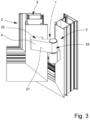
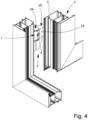
- FIG. 3 and 4 illustrate that the fastening unit 6 is not visually perceptible from the outside when the fitting part 1 is mounted.
- Fig. 3 shows a view of the outer side 27 of the band part 4.
- Fig. 4 In this context, the figure again shows the underside or attachment side 23 of the band part 4, which faces the profile 5.
- the outer side 27 is opposite the attachment side 23.
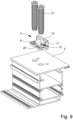
- the fastening unit 6 is arranged in a receptacle 7 of the band part 4, which can be seen in more detail in the exploded views according to the Fig. 5 and 6
- the recording 7 as such in volume part 4 is in the Fig. 7 in a schematic perspective view.
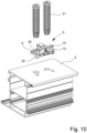
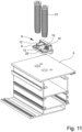
- the Fig. 8 to 11 show different embodiments of a fastening unit 6, which can each be arranged in a receptacle 7 of the band part 4.
- the Fig. 8 shows that the fastening unit 6 has a base plate 8 which can be firmly connected to the profile 5, which base plate 8 is also used in the embodiment according to the Fig. 10 and 11 is provided.
- the base plate 8 can in particular be connected to the profile 5, in particular the sash profile, in a force-locking manner.
- the Fig. 5 shows the individual components of a clamping device 9, which in different embodiments can also be found in the Fig. 12 and 13 can be seen.
- the bracing device 9 can have different components, but in particular can produce at least substantially the same effect, namely pressing the hinge part 4 against the sash profile or profile 5 and ultimately bracing it against profile 5.
- the clamping device 9 is provided for generating a relative movement between the fastening unit 6 and the band part 4 for clamping the band part 4 against the profile 5, so that the band part 4 is pressed against the profile 5 by clamping.
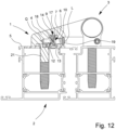
- the Fig. 12 shows that the clamping device 9 has at least one screw 10 for cooperating with the fastening unit 6 to generate the relative movement.
- the band part 4 at least one screw opening 11 for the screw 10 can be provided, which extends into the receptacle 7, which in particular in the Fig. 7 can be seen in more detail.
- the screw opening 11 can have an internal thread, which is preferably designed to be complementary to the external thread of the screw 10.
- the screw 10 in turn, can interact with the fastening unit 6 in a form-fitting manner, so that in particular at least one degree of freedom of movement of the fastening unit 6 is blocked or restricted by the screw 10.
- This form-fitting connection can in particular form a first form-fitting connection between the band part 4 and the fastening unit 6, wherein further Form-locking mechanisms can be provided.
- Each form-locking mechanism can, in particular, block at least one degree of freedom of movement.
- the screw 10 can also be connected to the fastening unit 6 in a force-locking manner.
- a positive connection has the particular advantage that the screw 10 fixedly arranged in the hinge part 4 can be used to clamp the hinge part 4 against the profile 5.
- an engagement bevel 12 can be provided on the fastening unit 6.
- the Fig. 12 and 13 differently designed attack slopes 12.
- An attack slope 12 can be characterized in particular by the fact that it runs obliquely, preferably at an angle between 10° and 70°, to the plane of the base plate 8, as is also the case with the Fig. 12 and 13 show.
- the engagement bevel 12 can be formed on the fastening unit 6 and, in particular, through interaction with the hinge part 4 or a complementary bevel on the hinge part 4, can lead to the tensioning of the hinge part 4 against the sash profile 5.
- the engagement bevel 12 can, in particular with the hinge part 4, create a further (second) positive connection between the fastening unit 6 and the hinge part 4.
- a further opening can be provided in the band part 4 opposite the screw opening 11.
- the further opening can then be designed, in particular, as a screw opening.
- the further opening serves to accommodate the screw 10, which has been passed through the fastening unit 6.
- the screw opening 11 and the further opening can have an axial offset from one another, in particular, which can result in the bracing.
- the further opening would also be part of the bracing device 9.
- the Fig. 5 and 6 show that the screw 10 is designed as a conical screw.
- a tapered screw 10 in the inserted state extends from both the Fig. 12 as well as from the Fig. 13 for different embodiments of the fastening unit 6.
- the tapered screw 10 can have an external thread at least in some areas, which is shown in the schematic exploded view according to the Fig. 5 and 6 is not apparent in more detail.
- the screw 10 can be firmly connected to the band part 4, in particular in that the screw opening 11 can have an internal thread complementary to the external thread of the screw 10.
- the front component of the screw 10, which can be designed as a cone and/or truncated cone, can have an external thread, but does not have to.
- This cone or truncated cone is used in particular for the (first) positive connection with the fastening unit 6.
- the positive connection can be effected in such a way that at least one degree of freedom of movement is blocked.
- the Fig. 12 shows that an axial offset is provided between the central axis L of the screw 10 and the central axis of the conical opening 13.
- This axial offset can be used for bracing.
- the central axis L of the screw 10 can result in an at least substantially approximate axis of symmetry of the screw 10 and, in particular, also indicate the longitudinal direction of the screw 10 in the direction of greatest extent and, in particular, also run through the center of gravity.
- the central axis of the conical opening 13 can also form an at least substantially approximate axis of symmetry. Both the central axis of the conical opening 13 and the central axis L of the screw 10 can run at least substantially parallel to the plane of the base plate 8, as is the case with Fig. 12 also shows.
- the Fig. 5 and 6 show that the fastening unit 6 has a tension stop 14.
- the tension stop 14 is in particular strip-shaped in the illustrated embodiment.
- a conical opening 13 is provided on the tensioning stop 14, which is also shown in more detail in the Fig. 8 and 10 (although these show different embodiments of the fastening unit 6).
- two conical openings 13 are provided for two screws 10. From the Fig. 8 and 9 as well as the Fig. 10 and 11 , each showing different embodiments of the fastening unit 6, it is clear that the attack slope 12 is provided on the side of the tensioning stop 14 opposite the conical opening 13, as can also be seen from the schematic sectional views according to the Fig. 12 and 13
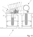
- the Fig. 12 a sectional view of a fastening unit 6 as shown in the Fig. 8 and 9 is shown, whereas the Fig. 13 shows a sectional view in which the fastening unit 6 according to the Fig. 10 and 11 is trained.
- the Fig. 13 shows an embodiment of the fastening unit 6, in which the engagement slope 12 is formed by a projection 15 on the tensioning stop 14 in a corresponding recess 16 in the receptacle 7.
- a recess 16 is also in the Fig. 7 shown in more detail, in which the receptacle 7 is visible.
- a projection 15 on the tension stop 14 is in the Fig. 11 described in more detail.
- the projection 15 is wedge-shaped and, in particular, elongated.
- the longitudinal extension can, in particular, be arranged at least substantially parallel to the support plane of the base plate 8 and, in particular, aligned in the longitudinal extension of the tensioning stop 14.
- the tensioning stop 14 can also be elongated.
- the projection 15 can also have other configurations.
- the Fig. 12 as well as the Fig. 8 and 9 show that the undercut 17 on the tensioning stop 14 is frustoconical.
- the projection 15 can also be conical or wedge-shaped.
- the projection 18 on the tensioning stop 14 can also be conical or frustoconical in further embodiments not shown in detail, although this is not shown in detail in the illustrated embodiments.
- the Fig. 13 shows that the central axis L of the screw 10 is offset from the central and/or transverse axis M of the projection 18 on the tensioning stop 14, which axis runs at least parallel to the central axis L of the screw 10. This offset can be between 0.2 and 1 mm.
- the central axis L of the screw 10 may be offset from the central and/or transverse axis Q of the undercut 17, whereby this offset may also be between 0.2 and 1 mm.
- Both the central axis L of the screw 10 and the central and/or transverse axis M, Q of the projection 15 or the undercut 17 are also arranged at least substantially parallel to the support plane of the base plate 8.
- components of the fastening unit 6 can also be attributed to the bracing device 9, such as in particular the bracing stop 14 or the engagement bevel 12 formed on the bracing stop 14.
- the bracing device 9 can also have components of the hinge part 4, such as in particular the screw opening 11.
- those components of the fitting part 1 are to be attributed to the bracing device 9 which lead to the bracing of the fitting part 1 against the profile 5 or which contribute to this bracing.
- the bracing device 9 has two screws 10, two screw openings 11 on the band part 4, and two projections 15 or undercuts 17 on the bracing stop 14.
- the Fig. 13 shows that a cover strip 19 for covering the screw 10 or the screw opening 11 is arranged on the outside of the hinge part 4; this cover strip 19 can be screwed to the hinge part 4.
- the Fig. 8 to 11 illustrate that the base plate 8 can be connected to the profile 5 in a force-locking manner, wherein the base plate 8 can preferably have openings 20 for arranging the screws 21, which are designed in particular as threaded screws, for fastening to the profile 5.
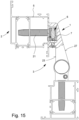
- Fig. 15 and 16 show further sectional views of a hinge 3 or the hinge part 4. From these views it can be seen that the attachment side 23 faces the profile 5 of the sash 2 or the frame and the outer side 27 is at least substantially free of openings for the arrangement of screws 10.
- the base plate 8 has, on its side facing the profile 5, at least one pin 22 for engaging in a pin opening of the profile 5.
- One or more pins 22 can be provided.
- Fig. 15 and 16 as well as the Fig. 12 and 13 illustrate that the fastening unit 6, in the assembled state of the band part 4 and the band 3, is completely received in the receptacle 7 and is covered on the outside by the band part 4.
- the Fig. 5 and 6 show that the hinge part 4 has a bearing sleeve 24 for receiving a hinge axis 26 and a fastening section 25 for fastening to the profile 5.
- the bearing sleeve 24 and the fastening section 25 are also shown in the Fig. 2 to 4 shown in more detail in the assembled state.
- the receptacle 7 for the fastening unit 6 can be provided on the underside in the fastening section 25, as shown in the Fig. 5 and 6 clarify.
Landscapes
- Engineering & Computer Science (AREA)
- Mechanical Engineering (AREA)
- Hinges (AREA)
Claims (10)
- Pièce de ferrure (1), prévue de préférence pour être utilisée comme pièce de ferrure (1) côté vantail ou côté cadre d'un vantail (2) ou d'un cadre, en particulier d'une paumelle (3) d'une porte et/ou d'une fenêtre, avec une partie de paumelle (4) et une unité de fixation (6) à fixer sur un profilé (5) du vantail (2) ou du cadre, l'unité de fixation (6) étant disposée dans un logement (7) de la partie de paumelle (4), l'unité de fixation (6) comportant une plaque de base (8) pouvant être reliée de manière fixe au profilé (5) et un dispositif de serrage (9) étant prévu pour générer un mouvement relatif entre l'unité de fixation (6) et la partie de paumelle (4) afin de serrer la partie de paumelle (4) contre le profilé (5), avec lequel la partie de paumelle (4) est pressée contre le profilé (5) par le serrage, le dispositif de serrage (9) comportant au moins une vis (10) destinée à coopérer avec l'unité de fixation (6) pour produire le mouvement relatif, et au moins un orifice de vis (11) s'étendant dans la partie de paumelle (4) jusqu'à l' logement (7) étant prévu pour la vis (10), une surface d'attaque inclinée (12) étant prévue sur l'unité de fixation (6) pour générer le mouvement relatif.la vis (10) étant réalisée sous forme de vis conique avec un cône à son extrémité, une ouverture conique (13) étant prévue sur l'unité de fixation (6) pour l'engagement du cône, un décalage axial étant prévu entre l'axe central (L) de la vis (10) et l'axe central de l'ouverture conique (13),une butée de serrage (14), en particulier, en forme de barre étant prévue sur l'unité de fixation (6) avec l'ouverture conique (13), la surface d'attaque (12) étant prévue sur le côté de la butée de serrage (14) opposé à l'ouverture conique (13), etla surface d'attaque (12) étant formée par une saillie (15) sur la butée de serrage (14) et un renfoncement correspondant (16) dans le logement (7) ou par une contre-dépouille (17) sur la butée de serrage (14) et une saillie correspondante (18) dans le logement (7).
- Pièce de ferrure selon l'une des revendications précédentes, caractérisée en ce que la saillie (15) ou la contre-dépouille (17) sur la butée de serrage (14) est de forme cunéiforme ou conique et/ou tronconique.
- Pièce de ferrure selon l'une des revendications précédentes, caractérisée en ce que l'axe central (L) de la vis (10) est décalé par rapport à l'axe central (L) de la vis (10) au moins sensiblement parallèle à l'axe central et/ou transversal (M, Q) de la saillie (15) ou de la contre-dépouille (17) sur la butée de serrage (14), le décalage étant compris entre 0,01 et 2 mm, de préférence entre 0,2 et 1mm.
- Pièce de ferrure selon l'une des revendications précédentes, caractérisée en ce que le dispositif de serrage (9) comporte deux vis (10), deux ouvertures de vis (11), deux saillies (15) ou deux contre-dépouilles (17) sur la butée de serrage (14).
- Pièce de ferrure selon l'une des revendications précédentes, caractérisée en ce qu'une baguette de recouvrement (19) destinée à recouvrir la vis (10) et/ou les ouvertures de vis (11) est disposée à l'extérieur sur la pièce de paumelle (4), de préférence vissée à la pièce de paumelle (4).
- Pièce de ferrure selon l'une des revendications précédentes, caractérisée en ce que la plaque de base (8) peut être reliée par adhérence au profilé (5) et en ce que, de préférence, la plaque de base (8) présente des ouvertures (20) pour la mise en place de vis (21) destinées à la fixation au profilé (5).
- Pièce de ferrure selon l'une des revendications précédentes, caractérisée en ce que la plaque de base (8) comporte, sur son côté tourné vers le profilé (5), au moins un tenon (22) destiné à s'engager dans une ouverture de tenon du profilé (5).
- Pièce de ferrure selon l'une des revendications précédentes, caractérisée en ce que l'unité de fixation (6), lorsque la partie de paumelle (4) est montée, est entièrement logée dans le logement (7) et recouverte par la partie de paumelle (4).
- Pièce de ferrure selon l'une des revendications précédentes, caractérisée en ce que l'ouverture de vis (11) de la partie de paumelle (4) est disposée sur le côté de fixation (23) de la partie de paumelle (4) tourné vers le profilé (5).
- Pièce de ferrure selon l'une des revendications précédentes, caractérisée en ce que la partie de paumelle (4) comporte une douille de palier (24) destinée à recevoir un axe de paumelle (26) et une partie de fixation (25) destinée à la fixation au profilé (5), le logement (7) pour l'unité de fixation (6) étant prévu sur la face inférieure de la partie de fixation (25).
Priority Applications (1)
| Application Number | Priority Date | Filing Date | Title |
|---|---|---|---|
| EP22209929.3A EP4375463B1 (fr) | 2022-11-28 | 2022-11-28 | Élément de ferrure |
Applications Claiming Priority (1)
| Application Number | Priority Date | Filing Date | Title |
|---|---|---|---|
| EP22209929.3A EP4375463B1 (fr) | 2022-11-28 | 2022-11-28 | Élément de ferrure |
Publications (3)
| Publication Number | Publication Date |
|---|---|
| EP4375463A1 EP4375463A1 (fr) | 2024-05-29 |
| EP4375463B1 true EP4375463B1 (fr) | 2025-06-18 |
| EP4375463C0 EP4375463C0 (fr) | 2025-06-18 |
Family
ID=84363664
Family Applications (1)
| Application Number | Title | Priority Date | Filing Date |
|---|---|---|---|
| EP22209929.3A Active EP4375463B1 (fr) | 2022-11-28 | 2022-11-28 | Élément de ferrure |
Country Status (1)
| Country | Link |
|---|---|
| EP (1) | EP4375463B1 (fr) |
Family Cites Families (2)
| Publication number | Priority date | Publication date | Assignee | Title |
|---|---|---|---|---|
| AT276142B (de) * | 1965-01-09 | 1969-11-10 | Schuermann & Co Heinz | Beschlag, wie Band, Fitsche, Drehlager, Griff od.dgl. für Fenster, Türen, Fassaden u.dgl. |
| DE1937564A1 (de) * | 1969-07-24 | 1971-02-25 | Mechanische Werkstaetten Dr Wa | Scharnier- oder Fischband od.dgl. zur schwenkbaren Verbindung des Fluegels mit dem feststehenden Rahmen bei Tueren,Fenster usw |
-
2022
- 2022-11-28 EP EP22209929.3A patent/EP4375463B1/fr active Active
Also Published As
| Publication number | Publication date |
|---|---|
| EP4375463A1 (fr) | 2024-05-29 |
| EP4375463C0 (fr) | 2025-06-18 |
Similar Documents
| Publication | Publication Date | Title |
|---|---|---|
| EP2297418B1 (fr) | Charniere | |
| EP0285229B2 (fr) | Charnière réglable, en particulier pour portes | |
| EP1893836B1 (fr) | Charnière de meuble | |
| EP1094183B1 (fr) | Dispositif de charnière | |
| EP2754813B1 (fr) | Charnière, notamment pour portes et fenêtres en plastique | |
| DE102011006023B3 (de) | Verstellbares Scharnierband | |
| EP4375463B1 (fr) | Élément de ferrure | |
| DE202005014145U1 (de) | Gelenkband für Türen oder Fenster | |
| EP4308780B1 (fr) | Charnière destinée à une porte ou une fenêtre | |
| WO2009125357A1 (fr) | Charnière | |
| EP1936083B1 (fr) | Dispositif de support pour une charnière d'une unité de fermeture | |
| EP1106763B1 (fr) | Penture pour portes, fenêtres ou telles | |
| EP1560996A1 (fr) | Systeme d'armatures pour portes en verre | |
| EP2304148A1 (fr) | Système de bande | |
| EP1988241A2 (fr) | Ensemble de charnière | |
| DE102007025857A1 (de) | Gelenkband für Türen oder Fenster | |
| EP3808927A1 (fr) | Agencement doté de cadre et d'un battant appliqué au cadre à l'aide de charnières | |
| EP0340455B2 (fr) | Pivot pour la connexion de deux battants d'une fenêtre, d'une porte ou similaire | |
| EP1979567A1 (fr) | Ensemble charnière permettant une liaison par l'intermédiaire d'une articulation à charnière | |
| EP4375464A1 (fr) | Élément de ferrure | |
| DE202007016708U1 (de) | Band für Türen, Fenster o.dgl. | |
| DE202007002494U1 (de) | Gelenkband für Türen und Fenster | |
| EP4632181A1 (fr) | Ligament articulaire | |
| DE19940132C2 (de) | Gelenkband | |
| DE20217852U1 (de) | Band für Türen, Fenster o.dgl. |
Legal Events
| Date | Code | Title | Description |
|---|---|---|---|
| PUAI | Public reference made under article 153(3) epc to a published international application that has entered the european phase |
Free format text: ORIGINAL CODE: 0009012 |
|
| STAA | Information on the status of an ep patent application or granted ep patent |
Free format text: STATUS: THE APPLICATION HAS BEEN PUBLISHED |
|
| AK | Designated contracting states |
Kind code of ref document: A1 Designated state(s): AL AT BE BG CH CY CZ DE DK EE ES FI FR GB GR HR HU IE IS IT LI LT LU LV MC ME MK MT NL NO PL PT RO RS SE SI SK SM TR |
|
| STAA | Information on the status of an ep patent application or granted ep patent |
Free format text: STATUS: REQUEST FOR EXAMINATION WAS MADE |
|
| 17P | Request for examination filed |
Effective date: 20240611 |
|
| RBV | Designated contracting states (corrected) |
Designated state(s): AL AT BE BG CH CY CZ DE DK EE ES FI FR GB GR HR HU IE IS IT LI LT LU LV MC ME MK MT NL NO PL PT RO RS SE SI SK SM TR |
|
| STAA | Information on the status of an ep patent application or granted ep patent |
Free format text: STATUS: EXAMINATION IS IN PROGRESS |
|
| 17Q | First examination report despatched |
Effective date: 20250123 |
|
| GRAP | Despatch of communication of intention to grant a patent |
Free format text: ORIGINAL CODE: EPIDOSNIGR1 |
|
| STAA | Information on the status of an ep patent application or granted ep patent |
Free format text: STATUS: GRANT OF PATENT IS INTENDED |
|
| GRAS | Grant fee paid |
Free format text: ORIGINAL CODE: EPIDOSNIGR3 |
|
| INTG | Intention to grant announced |
Effective date: 20250414 |
|
| GRAA | (expected) grant |
Free format text: ORIGINAL CODE: 0009210 |
|
| STAA | Information on the status of an ep patent application or granted ep patent |
Free format text: STATUS: THE PATENT HAS BEEN GRANTED |
|
| AK | Designated contracting states |
Kind code of ref document: B1 Designated state(s): AL AT BE BG CH CY CZ DE DK EE ES FI FR GB GR HR HU IE IS IT LI LT LU LV MC ME MK MT NL NO PL PT RO RS SE SI SK SM TR |
|
| REG | Reference to a national code |
Ref country code: GB Ref legal event code: FG4D Free format text: NOT ENGLISH |
|
| REG | Reference to a national code |
Ref country code: CH Ref legal event code: EP |
|
| REG | Reference to a national code |
Ref country code: DE Ref legal event code: R096 Ref document number: 502022004313 Country of ref document: DE |
|
| REG | Reference to a national code |
Ref country code: CH Ref legal event code: EP |
|
| REG | Reference to a national code |
Ref country code: IE Ref legal event code: FG4D Free format text: LANGUAGE OF EP DOCUMENT: GERMAN |
|
| U01 | Request for unitary effect filed |
Effective date: 20250618 |
|
| U07 | Unitary effect registered |
Designated state(s): AT BE BG DE DK EE FI FR IT LT LU LV MT NL PT RO SE SI Effective date: 20250626 |
|
| PG25 | Lapsed in a contracting state [announced via postgrant information from national office to epo] |
Ref country code: NO Free format text: LAPSE BECAUSE OF FAILURE TO SUBMIT A TRANSLATION OF THE DESCRIPTION OR TO PAY THE FEE WITHIN THE PRESCRIBED TIME-LIMIT Effective date: 20250918 Ref country code: GR Free format text: LAPSE BECAUSE OF FAILURE TO SUBMIT A TRANSLATION OF THE DESCRIPTION OR TO PAY THE FEE WITHIN THE PRESCRIBED TIME-LIMIT Effective date: 20250919 |
|
| PG25 | Lapsed in a contracting state [announced via postgrant information from national office to epo] |
Ref country code: HR Free format text: LAPSE BECAUSE OF FAILURE TO SUBMIT A TRANSLATION OF THE DESCRIPTION OR TO PAY THE FEE WITHIN THE PRESCRIBED TIME-LIMIT Effective date: 20250618 |
|
| PG25 | Lapsed in a contracting state [announced via postgrant information from national office to epo] |
Ref country code: RS Free format text: LAPSE BECAUSE OF FAILURE TO SUBMIT A TRANSLATION OF THE DESCRIPTION OR TO PAY THE FEE WITHIN THE PRESCRIBED TIME-LIMIT Effective date: 20250918 |
|
| U20 | Renewal fee for the european patent with unitary effect paid |
Year of fee payment: 4 Effective date: 20251120 |
|
| PG25 | Lapsed in a contracting state [announced via postgrant information from national office to epo] |
Ref country code: IS Free format text: LAPSE BECAUSE OF FAILURE TO SUBMIT A TRANSLATION OF THE DESCRIPTION OR TO PAY THE FEE WITHIN THE PRESCRIBED TIME-LIMIT Effective date: 20251018 |
|
| PG25 | Lapsed in a contracting state [announced via postgrant information from national office to epo] |
Ref country code: SM Free format text: LAPSE BECAUSE OF FAILURE TO SUBMIT A TRANSLATION OF THE DESCRIPTION OR TO PAY THE FEE WITHIN THE PRESCRIBED TIME-LIMIT Effective date: 20250618 |
|
| PG25 | Lapsed in a contracting state [announced via postgrant information from national office to epo] |
Ref country code: CZ Free format text: LAPSE BECAUSE OF FAILURE TO SUBMIT A TRANSLATION OF THE DESCRIPTION OR TO PAY THE FEE WITHIN THE PRESCRIBED TIME-LIMIT Effective date: 20250618 |
|
| PG25 | Lapsed in a contracting state [announced via postgrant information from national office to epo] |
Ref country code: PL Free format text: LAPSE BECAUSE OF FAILURE TO SUBMIT A TRANSLATION OF THE DESCRIPTION OR TO PAY THE FEE WITHIN THE PRESCRIBED TIME-LIMIT Effective date: 20250618 |
|
| PG25 | Lapsed in a contracting state [announced via postgrant information from national office to epo] |
Ref country code: SK Free format text: LAPSE BECAUSE OF FAILURE TO SUBMIT A TRANSLATION OF THE DESCRIPTION OR TO PAY THE FEE WITHIN THE PRESCRIBED TIME-LIMIT Effective date: 20250618 |
|
| PG25 | Lapsed in a contracting state [announced via postgrant information from national office to epo] |
Ref country code: ES Free format text: LAPSE BECAUSE OF FAILURE TO SUBMIT A TRANSLATION OF THE DESCRIPTION OR TO PAY THE FEE WITHIN THE PRESCRIBED TIME-LIMIT Effective date: 20250618 |
|
| PLBE | No opposition filed within time limit |
Free format text: ORIGINAL CODE: 0009261 |
|
| STAA | Information on the status of an ep patent application or granted ep patent |
Free format text: STATUS: NO OPPOSITION FILED WITHIN TIME LIMIT |