EP4375663A1 - Verfahren und vorrichtung zur bestimmung der relativen permittivität eines materials mittels eines bodendurchdringenden radars - Google Patents
Verfahren und vorrichtung zur bestimmung der relativen permittivität eines materials mittels eines bodendurchdringenden radars Download PDFInfo
- Publication number
- EP4375663A1 EP4375663A1 EP23211842.2A EP23211842A EP4375663A1 EP 4375663 A1 EP4375663 A1 EP 4375663A1 EP 23211842 A EP23211842 A EP 23211842A EP 4375663 A1 EP4375663 A1 EP 4375663A1
- Authority
- EP
- European Patent Office
- Prior art keywords
- relative permittivity
- delay
- values
- determining
- layer
- Prior art date
- Legal status (The legal status is an assumption and is not a legal conclusion. Google has not performed a legal analysis and makes no representation as to the accuracy of the status listed.)
- Granted
Links
Images


Classifications
-
- G—PHYSICS
- G01—MEASURING; TESTING
- G01N—INVESTIGATING OR ANALYSING MATERIALS BY DETERMINING THEIR CHEMICAL OR PHYSICAL PROPERTIES
- G01N33/00—Investigating or analysing materials by specific methods not covered by groups G01N1/00 - G01N31/00
- G01N33/24—Earth materials
-
- G—PHYSICS
- G01—MEASURING; TESTING
- G01S—RADIO DIRECTION-FINDING; RADIO NAVIGATION; DETERMINING DISTANCE OR VELOCITY BY USE OF RADIO WAVES; LOCATING OR PRESENCE-DETECTING BY USE OF THE REFLECTION OR RERADIATION OF RADIO WAVES; ANALOGOUS ARRANGEMENTS USING OTHER WAVES
- G01S13/00—Systems using the reflection or reradiation of radio waves, e.g. radar systems; Analogous systems using reflection or reradiation of waves whose nature or wavelength is irrelevant or unspecified
- G01S13/02—Systems using reflection of radio waves, e.g. primary radar systems; Analogous systems
- G01S13/06—Systems determining position data of a target
- G01S13/42—Simultaneous measurement of distance and other co-ordinates
-
- G—PHYSICS
- G01—MEASURING; TESTING
- G01S—RADIO DIRECTION-FINDING; RADIO NAVIGATION; DETERMINING DISTANCE OR VELOCITY BY USE OF RADIO WAVES; LOCATING OR PRESENCE-DETECTING BY USE OF THE REFLECTION OR RERADIATION OF RADIO WAVES; ANALOGOUS ARRANGEMENTS USING OTHER WAVES
- G01S13/00—Systems using the reflection or reradiation of radio waves, e.g. radar systems; Analogous systems using reflection or reradiation of waves whose nature or wavelength is irrelevant or unspecified
- G01S13/88—Radar or analogous systems specially adapted for specific applications
- G01S13/885—Radar or analogous systems specially adapted for specific applications for ground probing
-
- G—PHYSICS
- G01—MEASURING; TESTING
- G01S—RADIO DIRECTION-FINDING; RADIO NAVIGATION; DETERMINING DISTANCE OR VELOCITY BY USE OF RADIO WAVES; LOCATING OR PRESENCE-DETECTING BY USE OF THE REFLECTION OR RERADIATION OF RADIO WAVES; ANALOGOUS ARRANGEMENTS USING OTHER WAVES
- G01S7/00—Details of systems according to groups G01S13/00, G01S15/00, G01S17/00
- G01S7/02—Details of systems according to groups G01S13/00, G01S15/00, G01S17/00 of systems according to group G01S13/00
- G01S7/41—Details of systems according to groups G01S13/00, G01S15/00, G01S17/00 of systems according to group G01S13/00 using analysis of echo signal for target characterisation; Target signature; Target cross-section
- G01S7/411—Identification of targets based on measurements of radar reflectivity
-
- G—PHYSICS
- G01—MEASURING; TESTING
- G01V—GEOPHYSICS; GRAVITATIONAL MEASUREMENTS; DETECTING MASSES OR OBJECTS; TAGS
- G01V3/00—Electric or magnetic prospecting or detecting; Measuring magnetic field characteristics of the earth, e.g. declination, deviation
- G01V3/12—Electric or magnetic prospecting or detecting; Measuring magnetic field characteristics of the earth, e.g. declination, deviation operating with electromagnetic waves
-
- G—PHYSICS
- G01—MEASURING; TESTING
- G01S—RADIO DIRECTION-FINDING; RADIO NAVIGATION; DETERMINING DISTANCE OR VELOCITY BY USE OF RADIO WAVES; LOCATING OR PRESENCE-DETECTING BY USE OF THE REFLECTION OR RERADIATION OF RADIO WAVES; ANALOGOUS ARRANGEMENTS USING OTHER WAVES
- G01S13/00—Systems using the reflection or reradiation of radio waves, e.g. radar systems; Analogous systems using reflection or reradiation of waves whose nature or wavelength is irrelevant or unspecified
- G01S13/02—Systems using reflection of radio waves, e.g. primary radar systems; Analogous systems
- G01S2013/0236—Special technical features
- G01S2013/0245—Radar with phased array antenna
Definitions
- the invention relates to the field of ground penetrating radars and more precisely to non-destructive devices and methods making it possible to characterize the composition of the ground or more generally of a material.
- the invention relates more precisely to a method and a device making it possible to determine the dielectric characteristics of the ground, in other words the relative permittivities and the thicknesses of the different layers which constitute the ground. This information then makes it possible to improve radar detection techniques in order to locate and identify underground targets such as pipes, pipes or even mines or more generally any type of object buried in the ground or in any material.
- Methods for detecting buried targets using ground-penetrating radar are generally based on algorithms which require, in their parameters, a precise estimation of the relative permittivities of the different soil layers. Usually this information is not known or is roughly estimated as an average value for the entire soil structure. These approximations can increase uncertainties in the results of detection and characterization of underground targets.
- the invention is described in the context of the detection of targets buried in the ground but the invention applies more generally to targets buried in any material which may be different from the ground.
- the invention also applies to medical microwave imaging to detect, for example, veins under the skin or to non-destructive microwave testing to estimate the thickness of concrete layers of an industrial structure.
- the first known method is based on fitting a hyperbola curve.
- hyperbolas can be formed by the travel times of the reflected waves over the distance traveled by radar.
- the shape of each hyperbola is given mainly from two elements: the design of the radar, in particular the geometric arrangement of the antennas, and the dielectric properties of the propagation medium.
- the shape of the radar system is static but the portion of the target illuminated by the radar increases with depth, and the contour of the curve then changes with depth.
- the shape of each individual hyperbola is therefore a function of the depth and dielectric properties of the medium.
- Migration is a form of mathematical processing whose main goal is to more precisely define linear objects. Correctly applied, the process reduces the hyperbolas at a point in the data acquired by the radar. For linear objects, this makes their position and depth much easier to define because it is no longer necessary to exploit the full hyperbola.
- There are a wide variety of different migration methods including the one described in reference [5].
- the main parameter required to reduce the hyperbola to a point corresponds to the dielectric properties of the soil as taught in reference [6]. This makes the migration process a way to increase the accuracy of curve fitting since the process only works correctly if the applied ground transmission speed is accurate.
- a disadvantage of these methods is their relative imprecision when the material, in particular soil, is composed of several layers of different permittivities.
- the invention proposes a new method making it possible to precisely estimate the relative permittivities and the thicknesses of each layer of a material such as soil.
- the method is based on measurement acquisitions carried out by a ground penetrating radar equipped with several transmitting antennas and several receiving antennas (MIMO “Multiple Input Multiple Output” radar).
- MIMO Multiple Input Multiple Output
- the proposed method is based on a particular algorithm which aims to estimate the most probable couples (delay, relative permittivity) which correspond to the different layers composing the soil structure.
- the step of extracting from each impulse response, the components relating to multiple paths of the radar signal is carried out by means of a high resolution algorithm.
- x c p the coordinate of the estimated target
- x Tx j the coordinate of each transmitting antenna
- x Rx i the coordinate of each receiving antenna
- ⁇ y the distance between a transmitting antenna and a receiving antenna
- v g the average speed of propagation of the signal in the material
- ⁇ p the estimated value of a delay.
- the path, among the two paths, having the factor of the weakest correlation is eliminated.
- the detection threshold used for the first layer during the preliminary phase has a value lower than the detection threshold used for the subsequent layers.
- the material is soil.
- the invention also relates to a device for determining the relative permittivity of a material comprising a ground penetrating radar provided with NTx transmitting antennas and NRx receiving antennas and a processing unit configured to implement the steps of the method according to the invention.
- the invention also relates to a computer program comprising code instructions which cause the device according to the invention to execute the steps of the method according to the invention as well as a computer-readable medium, on which the computer program according to the invention.
- FIG. 1 represents, on a flowchart, the steps of implementing a method for determining the dielectric characteristics of the ground according to a first embodiment of the invention.
- This first embodiment applies advantageously when the thickness of the first layer of soil is sufficiently large compared to the temporal resolution of the radar which depends on its operating carrier frequency.
- the first step 101 consists of acquiring a set of measurements using a ground penetrating radar having NTx antennas operating in transmission and NRx antennas operating in reception, with NTx, NRx positive integers at least equal to 2.
- the figure 2a schematizes an example of an RPS radar having five transmitting antennas and four receiving antennas and moving on the ground surface S by carrying out several successive temporal acquisitions.
- FIG. 2b represents another example of ground penetrating radar RPS in top view in an (x,y) plane parallel to the ground plane.
- the receiving NRx antennas are each arranged at a fixed distance ⁇ y from the transmitting NTx antennas.
- Each transmitting antenna has a coordinate X Rxi along the x axis and is separated by a distance ⁇ y with a corresponding receiving antenna along the y axis.
- the RPS radar is placed close to the ground to operate in the near field.
- Step 101 of acquiring radar measurements thus consists of moving the RPS radar on the ground surface S to be analyzed and measuring, for each pair associating a transmitting antenna and a receiving antenna, an impulse response of the radar signal h ( Rx i , Tx j , ⁇ ), where Rx i designates a receiving antenna, Tx j designates a transmitting antenna and ⁇ designates the time delay.
- the impulse response gives the amplitude values as a function of the delay ⁇ .
- the impulse responses can be organized in the form of a number NTx of vectors of dimension NRx.
- step 102 a method of extracting components relating to multiple paths is then applied to the impulse responses.
- the method used is the CLEAN method or a high resolution method or any other appropriate method.
- step 102 The purpose of step 102 is to detect multiple paths of the signal which correspond to reflections on buried targets. Each path is characterized by a delay ⁇ p and an amplitude
- the CLEAN method is applied by means of a rectangle filter which is defined by a number of samples whose amplitudes are forced to zero around the detected local maximum.
- a so-called beamwidth filter approach consists of searching for the closest local minima around the detected local maximum, then forcing the sample forming the detected pulse to zero.
- step 102 we obtain for each transmitting antenna Tx j a 2D matrix of dimension NP by NRx which gives the values of the amplitudes of each path ⁇ p detected for each receiving antenna Rx i , with NP the number of journeys detected.
- the following steps 103,104 consist of modeling each signal path using a hyperbolic curve which depends on the geometry of the radar, the dielectric characteristics of the ground and the position of the targets on which the signal paths are reflected.
- equation (1) which models a hyperbolic curve can be adapted according to the geometry of the radar.
- step 104 equation (1) is applied to estimate the delay t modeled from a hyperbolic curve, for different hypotheses of relative permittivity values ⁇ r and for all the receiving antennas.
- step 105 we then search, in the impulse responses, for each reception antenna, the amplitude a ip associated with the delay ⁇ p which is closest to the delay t calculated in step 104. In other words, we retains the index p which minimizes the difference between t and ⁇ p among all the delays detected for a receiving antenna.
- step 104 consists of calculating a delay vector t of dimension equal to the number of antennas receiving NRx.
- This vector has the form of the hyperbola formed by a delay target ⁇ p and x c p .
- Another option consists of carrying out an interpolation on the amplitude obtained for the delay ⁇ p in order to estimate the value of the amplitude corresponding to the delay t.
- step 105 several amplitudes are retained in a time window of dimension N+1 around the amplitude a ip associated with the delay ⁇ p which is closest to the delay t.
- step 106 we then calculate a correlation coefficient also called resemblance metric which aims to estimate the level of resemblance between the amplitudes determined in step 105 on all the reception antennas.
- the objective of step 105 is to identify whether the amplitudes of the selected path are substantially identical for all the receiving antennas, which should normally be the case if the path is correctly estimated.
- M is a normalization factor dimensioned such that the correlation coefficient is 1 when all the amplitudes are equal and tends to 0 when they are significantly different.
- N is taken equal to 0 and relation (4) is simplified to:
- ⁇ i 1 NRx has ip j 2
- Steps 104 to 106 are iterated for all relative permittivity assumptions. Steps 103 to 106 are iterated for all delay indices p.
- NTx correlation matrices also called coherence matrices of dimensions NP by NE, where NP is the number of delays and NE the number of hypotheses of relative permittivities.
- the values of a correlation matrix are the correlation coefficients R ( t, ⁇ r ) for each delay, relative permittivity pair.
- step 107 all the values of the NTx correlation matrices are compared to a predetermined detection threshold th1 whose value is included in the interval ]0.5; 1[.
- threshold th1 allows you to be more selective in order to eliminate a greater number of values. Conversely, a lower value can be chosen when the hyperbolic curve model has more uncertainties.
- step 107 we obtain a 3D matrix (delay, relative permittivity and correlation coefficient) of dimensions NP' by NTx by NE' or NP' and NE' correspond respectively to the maximum numbers of paths and permittivity assumptions for each transmitting antenna.
- the matrix obtained is of the following form, where each column represents the significant events detected by all the receiving antennas for a single transmitting antenna.
- HAS ⁇ 11 ⁇ ⁇ 1 NTx ⁇ ⁇ ⁇ ⁇ NP ′ 1 ⁇ ⁇ NP ′ NTx
- the first column of this matrix contains on each entry the same delay value ⁇ pi , the second column contains the different values retained for relative permittivity and the third column contains the correlation coefficient values associated with the delay, permittivity couple.
- Step 108 then consists of filtering the values of matrix A in order to retain only a vector of delay, permittivity couples for which all the delay values are different.
- step 108 consists first of all in maintaining the common multiple paths between the different transmitting antennas.
- Each path is defined by a couple (delay, relative permittivity).
- Common paths are those that have close delays based on a given error criterion. The difference between two delays is compared in absolute value to an error threshold which depends on the targeted scenario and in particular on the speed of movement of the radar during its movement during the acquisition step 101 but also on the size of the antenna network.
- the trips are sorted in ascending order of delay values. If two consecutive paths have approximately equal relative permittivities, only the path with the highest delay is kept, the others are deleted.
- step 108 we therefore obtain a final vector whose dimension corresponds to the number of layers of the soil estimated and each component of which corresponds to a delay, relative permittivity couple.
- Step 109 consists of the final step which aims to estimate the relative permittivities of each layer of the soil and its thickness.
- equation (6) can be replaced by equation (7):
- v int , not 1 t not ⁇ t not ⁇ 1 t not v g , not ⁇ t not ⁇ 1 v g , not ⁇ 1
- n is an imaginary value.
- Step 109 consists first of determining the path which most probably corresponds to the first layer as being the one which has the highest correlation factor.
- This path therefore makes it possible to define the relative permittivity ⁇ r 1 and the thickness w 1 of the first layer.
- the detection threshold used in step 107 for the first layer has a lower value than that used for the upper layers because the model used for the first layer is less precise.
- the correlation coefficient for the path obtained for the first layer on the basis of equation (7) is compared with that obtained for the first layer based on equation (1) and only the one with the highest correlation coefficient is kept.
- the relative permittivity values obtained for each layer of the soil are interpolated in order to determine a curve of evolution of the relative permittivity as a function of the depth of the soil or even a probability distribution of relative permittivity as a function of soil depth.
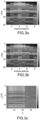
- THE figures 3a, 3b and 3c give examples of the outputs of certain intermediate steps of the method according to the invention for a transmitting antenna.
- FIG. 3a represents the impulse responses obtained in step 101 for a transmitting antenna in the form of a matrix giving the values of the path amplitudes measured for different receiving antennas, with a number of receiving antennas N_Rx equal to 8.
- FIG. 3b represents the results obtained at the output of step 102 in the form of circles positioned on the matrix of the figure 3a to identify detected multipaths
- figure 3c represents an example of a correlation matrix giving the values of the correlation coefficients for each pair of delay and relative permittivity.
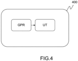
- the device 400 comprises at least one GPR radar signal acquisition module, for example a multi-antenna ground penetrating radar, and a processing unit UT configured to execute the implementation steps of the invention based on the measurements. provided by the GPR radar.
- GPR radar signal acquisition module for example a multi-antenna ground penetrating radar
- processing unit UT configured to execute the implementation steps of the invention based on the measurements. provided by the GPR radar.
- the processing unit UT can be produced in software and/or hardware form, in particular by using one or more processor(s) and one or more memory(s).
- the processor can be a generic processor, a specific processor, an application-specific integrated circuit (also known as ASIC for “Application-Specific Integrated Circuit”) or an array of in situ programmable gates (also known as the English name of FPGA for “Field-Programmable Gate Array”).
- the invention can be used in conjunction with a state-of-the-art radar target detection algorithm.
- the invention can be used to detect mines or underground pipelines.
Landscapes
- Engineering & Computer Science (AREA)
- Remote Sensing (AREA)
- Radar, Positioning & Navigation (AREA)
- Physics & Mathematics (AREA)
- General Physics & Mathematics (AREA)
- Electromagnetism (AREA)
- Life Sciences & Earth Sciences (AREA)
- Computer Networks & Wireless Communication (AREA)
- Chemical & Material Sciences (AREA)
- General Life Sciences & Earth Sciences (AREA)
- Geology (AREA)
- Health & Medical Sciences (AREA)
- Environmental & Geological Engineering (AREA)
- General Health & Medical Sciences (AREA)
- Medicinal Chemistry (AREA)
- Analytical Chemistry (AREA)
- Biochemistry (AREA)
- Food Science & Technology (AREA)
- Immunology (AREA)
- Pathology (AREA)
- Geophysics (AREA)
- Radar Systems Or Details Thereof (AREA)
- Measurement Of Resistance Or Impedance (AREA)
- Geophysics And Detection Of Objects (AREA)
- Investigating Or Analyzing Materials By The Use Of Electric Means (AREA)
Applications Claiming Priority (1)
| Application Number | Priority Date | Filing Date | Title |
|---|---|---|---|
| FR2212411A FR3142553B1 (fr) | 2022-11-28 | 2022-11-28 | Méthode et dispositif pour déterminer la permittivité relative d’un matériau à l’aide d’un radar à pénétration de sol |
Publications (2)
| Publication Number | Publication Date |
|---|---|
| EP4375663A1 true EP4375663A1 (de) | 2024-05-29 |
| EP4375663B1 EP4375663B1 (de) | 2025-08-27 |
Family
ID=85792073
Family Applications (1)
| Application Number | Title | Priority Date | Filing Date |
|---|---|---|---|
| EP23211842.2A Active EP4375663B1 (de) | 2022-11-28 | 2023-11-23 | Verfahren und vorrichtung zur bestimmung der relativen permittivität eines materials mittels eines bodendurchdringenden radars |
Country Status (3)
| Country | Link |
|---|---|
| US (1) | US12529780B2 (de) |
| EP (1) | EP4375663B1 (de) |
| FR (1) | FR3142553B1 (de) |
Families Citing this family (3)
| Publication number | Priority date | Publication date | Assignee | Title |
|---|---|---|---|---|
| FR3166978A1 (fr) | 2024-10-02 | 2026-04-03 | Commissariat à l'Energie Atomique et aux Energies Alternatives | Méthode de détermination de propriétés radioélectriques d’un milieu non-homogène au moyen d’un système de détection radiofréquence |
| FR3166980A1 (fr) | 2024-10-02 | 2026-04-03 | Commissariat à l'Energie Atomique et aux Energies Alternatives | Méthode de détermination de propriétés radioélectriques d’un milieu non-homogène au moyen d’un système de détection radiofréquence |
| FR3166979A1 (fr) | 2024-10-02 | 2026-04-03 | Commissariat à l'Energie Atomique et aux Energies Alternatives | Méthode de détermination de propriétés radioélectriques d’un milieu stratifié au moyen d’un système de détection radiofréquences |
Family Cites Families (3)
| Publication number | Priority date | Publication date | Assignee | Title |
|---|---|---|---|---|
| US6246354B1 (en) * | 1998-10-15 | 2001-06-12 | Hilti Aktiengesellschaft | Method of determining of permittivity of concrete and use of the method |
| US6501414B2 (en) * | 2001-04-02 | 2002-12-31 | The United States Of America As Represented By The United States National Aeronautics And Space Administration | Method for locating a concealed object |
| JP7162208B2 (ja) * | 2018-06-22 | 2022-10-28 | 株式会社カナン・ジオリサーチ | 含水比マッピング方法及び含水比マッピング装置 |
-
2022
- 2022-11-28 FR FR2212411A patent/FR3142553B1/fr active Active
-
2023
- 2023-11-23 EP EP23211842.2A patent/EP4375663B1/de active Active
- 2023-11-27 US US18/520,406 patent/US12529780B2/en active Active
Non-Patent Citations (12)
| Title |
|---|
| DONGZEJUN ET AL.: "3D Migration Depth Focus Velocity Analysis of Hand-Held Ground Penetrating Radar", GEOSCIENCES, vol. 12, no. 4, 2022, pages 178 |
| FORTEEMANUELEMICHELE PIPAN: "Review of multi-offset GPR applications: Data acquisition, processing and analysis", SIGNAL PROCESSING, vol. 132, 2017, pages 210 - 220, XP029809644, DOI: 10.1016/j.sigpro.2016.04.011 |
| GROTE, K.S. HUBBARDY. RUBIN: "GPR monitoring of volumetric water content in soils applied to highway construction and maintenance", THE LEADING EDGE, vol. 21, no. 5, 2002, pages 482 - 504 |
| ÔZDEMIRCANER ET AL.: "A review on migration methods in B-scan ground penetrating radar imaging", MATHEMATICAL PROBLEMS IN ENGINEERING, vol. 2014, 2014 |
| R.-M. CRAMERR. A. SCHOLTZM. Z. WIN: "Evaluation of an ultrawide-band propagation channel", IEEE TRANSACTIONS ON ANTENNAS AND PROPAGATION, vol. 50, no. 5, 2002, pages 561 - 570, XP011068520 |
| SCHNEIDERWILLIAM A.: "Developments in seismic data processing and analysis (1968-1970", GEOPHYSICS, vol. 36, no. 6, 1971, pages 1043 - 1073, XP001345363 |
| SERKAN, S.V. BORECKY.: "Estimation methods for obtaining GPR signal velocity", PROCEEDINGS OF THE THIRD INTERLATIONAL CONFÉRENCE ON ACSEE, ZURICH, SWITZERLAND, 2015 |
| U. SCHWARZ: "Mathematical-statistical description of the itérative beam removing technique (method clean", ASTRONOMY AND ASTROPHYSICS, vol. 65, 1978, pages 345 |
| UMBERTO SPAGNOLINI: "Permittivity Measurements of Multilayered Media With Monostatic Pulse Radar", IEEE TRANSACTIONS ON GEOSCIENCE AND REMOTE SENSING, IEEE, USA, vol. 35, no. 2, March 1997 (1997-03-01), XP011020837, ISSN: 0196-2892 * |
| WALIA A ET AL: "Reviewing methods for determination of Dielectric Constant required to Calibrate GPR Study for Asphalt Layers", IOP CONFERENCE SERIES: MATERIALS SCIENCE AND ENGINEERING, vol. 1075, 8 March 2021 (2021-03-08), GB, pages 012026, XP093059141, ISSN: 1757-8981, DOI: 10.1088/1757-899X/1075/1/012026 * |
| WANG HUI ET AL: "Deep-Learning-Based Method for Estimating Permittivity of Ground-Penetrating Radar Targets", REMOTE SENSING, vol. 14, no. 17, 31 August 2022 (2022-08-31), pages 4293, XP093059139, DOI: 10.3390/rs14174293 * |
| ZHANG WENJI ET AL: "MIMO Ground Penetrating Radar Imaging Through Multilayered Subsurface Using Total Variation Minimization", IEEE TRANSACTIONS ON GEOSCIENCE AND REMOTE SENSING, IEEE, USA, vol. 57, no. 4, 25 March 2019 (2019-03-25), pages 2107 - 2115, XP011716749, ISSN: 0196-2892, [retrieved on 20190325], DOI: 10.1109/TGRS.2018.2871463 * |
Also Published As
| Publication number | Publication date |
|---|---|
| US12529780B2 (en) | 2026-01-20 |
| US20240176012A1 (en) | 2024-05-30 |
| FR3142553B1 (fr) | 2024-11-15 |
| EP4375663B1 (de) | 2025-08-27 |
| FR3142553A1 (fr) | 2024-05-31 |
Similar Documents
| Publication | Publication Date | Title |
|---|---|---|
| EP4375663B1 (de) | Verfahren und vorrichtung zur bestimmung der relativen permittivität eines materials mittels eines bodendurchdringenden radars | |
| FR3111994A1 (fr) | Procédé de détection de cible pour radar à pénétration de sol et radar associé | |
| EP2344902B1 (de) | Verfahren zur bestimmung der ankunftsrichtung im hinblick auf lage einer hochfrequenten elektromagnetischen welle | |
| EP3252423B1 (de) | Adaptives detektionsverfahren eines ziels mithilfe einer radarvorrichtung in präsenz von stationären interferenzen, und radar und zielsuchgerät einer rakete, das ein solches verfahren anwendet | |
| EP3230764B1 (de) | Radardetektionssystem zur unterscheidung von regenechos und radar zur durchführung dieses verfahrens | |
| WO2015177172A1 (fr) | Contraintes conjointes de transitivite de differences temporelles et effet dopler multibandes pour la separation, caracterisation, et localisation de sources sonores par acoustique passive | |
| EP2544020B1 (de) | Verfahren und Vorrichtung zur Detektion eines Ziels, das von starken Energiereflektoren maskiert wird | |
| EP3295212B1 (de) | Verfahren und vorrichtung für sondierung mittels wellenausbreitung | |
| EP1582888A1 (de) | Verfahren zur breitbandigen blinden Ortung von einem oder mehreren Sendern durch einen sich vorbeibewegenden Träger | |
| EP2737337B1 (de) | Vorrichtung für clutter-resistente zielerkennung | |
| EP2196821A1 (de) | Verfahren zum multidimensionalen zeitlichen kinematischen Filtern von Radarechozeichen von einem Antennenmast zum anderen | |
| EP0410826A1 (de) | Iteratives Bewegungsabschätzungsverfahren zwischen einem Referenzbild und einem aktuellen Bild, und Verfahren zu ihrer Herstellung | |
| EP3526597B1 (de) | Verfahren und vorrichtung zum erfassen und charakterisieren eines reflektierenden elements in einem objekt | |
| EP3236280B1 (de) | Automatische berechnung einer abmessung einer mobilen plattform | |
| WO2009086928A1 (fr) | Procede, systeme et installation de detection pour garantir l'unicite de passage d'un objet | |
| EP4254007A1 (de) | Verfahren zur detektion vergrabener längsstrukturen mittels eines bodendurchdringenden radars | |
| FR3070768A1 (fr) | Procede de classification automatique d'un navire cible et systeme radar associe | |
| EP3400457B1 (de) | Verfahren zum löschen eines signals aus einem bordradar | |
| EP4722763A1 (de) | Verfahren zur bestimmung von radioelektrischen eigenschaften eines nichthomogenen mediums mittels eines hochfrequenzdetektionssystems | |
| FR3156545A1 (fr) | Procédé de mesure de relief par une antenne à profil de gain connu | |
| EP4254008A1 (de) | Verfahren zur detektion vergrabener längsstrukturen mittels eines bodendurchdringenden radars | |
| EP4722764A1 (de) | Verfahren zur bestimmung der funkeigenschaften eines schichtmediums mittels eines radiofrequenzdetektionssystems | |
| EP4722765A1 (de) | Verfahren zur bestimmung von radioelektrischen eigenschaften eines nichthomogenen mediums mittels eines hochfrequenzdetektionssystems | |
| FR2769373A1 (fr) | Procede de detection doppler de cibles a vitesse radiale faible ou nulle | |
| FR3137453A1 (fr) | Procédé d’identification automatique d’une source acoustique a partir d’un signal acoustique produit |
Legal Events
| Date | Code | Title | Description |
|---|---|---|---|
| PUAI | Public reference made under article 153(3) epc to a published international application that has entered the european phase |
Free format text: ORIGINAL CODE: 0009012 |
|
| STAA | Information on the status of an ep patent application or granted ep patent |
Free format text: STATUS: REQUEST FOR EXAMINATION WAS MADE |
|
| 17P | Request for examination filed |
Effective date: 20231123 |
|
| AK | Designated contracting states |
Kind code of ref document: A1 Designated state(s): AL AT BE BG CH CY CZ DE DK EE ES FI FR GB GR HR HU IE IS IT LI LT LU LV MC ME MK MT NL NO PL PT RO RS SE SI SK SM TR |
|
| RAP3 | Party data changed (applicant data changed or rights of an application transferred) |
Owner name: COMMISSARIAT A L'ENERGIE ATOMIQUE ET AUX ENERGIESALTERNATIVES |
|
| GRAP | Despatch of communication of intention to grant a patent |
Free format text: ORIGINAL CODE: EPIDOSNIGR1 |
|
| STAA | Information on the status of an ep patent application or granted ep patent |
Free format text: STATUS: GRANT OF PATENT IS INTENDED |
|
| RIC1 | Information provided on ipc code assigned before grant |
Ipc: G01S 7/41 20060101ALI20250314BHEP Ipc: G01V 3/12 20060101ALI20250314BHEP Ipc: G01S 13/88 20060101ALI20250314BHEP Ipc: G01N 33/24 20060101AFI20250314BHEP |
|
| INTG | Intention to grant announced |
Effective date: 20250326 |
|
| GRAS | Grant fee paid |
Free format text: ORIGINAL CODE: EPIDOSNIGR3 |
|
| GRAA | (expected) grant |
Free format text: ORIGINAL CODE: 0009210 |
|
| STAA | Information on the status of an ep patent application or granted ep patent |
Free format text: STATUS: THE PATENT HAS BEEN GRANTED |
|
| AK | Designated contracting states |
Kind code of ref document: B1 Designated state(s): AL AT BE BG CH CY CZ DE DK EE ES FI FR GB GR HR HU IE IS IT LI LT LU LV MC ME MK MT NL NO PL PT RO RS SE SI SK SM TR |
|
| REG | Reference to a national code |
Ref country code: CH Ref legal event code: EP |
|
| REG | Reference to a national code |
Ref country code: DE Ref legal event code: R096 Ref document number: 602023006104 Country of ref document: DE |
|
| REG | Reference to a national code |
Ref country code: IE Ref legal event code: FG4D Free format text: LANGUAGE OF EP DOCUMENT: FRENCH |
|
| REG | Reference to a national code |
Ref country code: NL Ref legal event code: MP Effective date: 20250827 |
|
| PG25 | Lapsed in a contracting state [announced via postgrant information from national office to epo] |
Ref country code: IS Free format text: LAPSE BECAUSE OF FAILURE TO SUBMIT A TRANSLATION OF THE DESCRIPTION OR TO PAY THE FEE WITHIN THE PRESCRIBED TIME-LIMIT Effective date: 20251227 |
|
| PGFP | Annual fee paid to national office [announced via postgrant information from national office to epo] |
Ref country code: DE Payment date: 20251127 Year of fee payment: 3 |
|
| PG25 | Lapsed in a contracting state [announced via postgrant information from national office to epo] |
Ref country code: NO Free format text: LAPSE BECAUSE OF FAILURE TO SUBMIT A TRANSLATION OF THE DESCRIPTION OR TO PAY THE FEE WITHIN THE PRESCRIBED TIME-LIMIT Effective date: 20251127 |
|
| REG | Reference to a national code |
Ref country code: LT Ref legal event code: MG9D |
|
| PG25 | Lapsed in a contracting state [announced via postgrant information from national office to epo] |
Ref country code: PT Free format text: LAPSE BECAUSE OF FAILURE TO SUBMIT A TRANSLATION OF THE DESCRIPTION OR TO PAY THE FEE WITHIN THE PRESCRIBED TIME-LIMIT Effective date: 20251229 |
|
| PG25 | Lapsed in a contracting state [announced via postgrant information from national office to epo] |
Ref country code: FI Free format text: LAPSE BECAUSE OF FAILURE TO SUBMIT A TRANSLATION OF THE DESCRIPTION OR TO PAY THE FEE WITHIN THE PRESCRIBED TIME-LIMIT Effective date: 20250827 |
|
| PG25 | Lapsed in a contracting state [announced via postgrant information from national office to epo] |
Ref country code: HR Free format text: LAPSE BECAUSE OF FAILURE TO SUBMIT A TRANSLATION OF THE DESCRIPTION OR TO PAY THE FEE WITHIN THE PRESCRIBED TIME-LIMIT Effective date: 20250827 Ref country code: NL Free format text: LAPSE BECAUSE OF FAILURE TO SUBMIT A TRANSLATION OF THE DESCRIPTION OR TO PAY THE FEE WITHIN THE PRESCRIBED TIME-LIMIT Effective date: 20250827 |
|
| PGFP | Annual fee paid to national office [announced via postgrant information from national office to epo] |
Ref country code: FR Payment date: 20251120 Year of fee payment: 3 |
|
| PG25 | Lapsed in a contracting state [announced via postgrant information from national office to epo] |
Ref country code: GR Free format text: LAPSE BECAUSE OF FAILURE TO SUBMIT A TRANSLATION OF THE DESCRIPTION OR TO PAY THE FEE WITHIN THE PRESCRIBED TIME-LIMIT Effective date: 20251128 |
|
| PG25 | Lapsed in a contracting state [announced via postgrant information from national office to epo] |
Ref country code: SE Free format text: LAPSE BECAUSE OF FAILURE TO SUBMIT A TRANSLATION OF THE DESCRIPTION OR TO PAY THE FEE WITHIN THE PRESCRIBED TIME-LIMIT Effective date: 20250827 |
|
| PG25 | Lapsed in a contracting state [announced via postgrant information from national office to epo] |
Ref country code: LV Free format text: LAPSE BECAUSE OF FAILURE TO SUBMIT A TRANSLATION OF THE DESCRIPTION OR TO PAY THE FEE WITHIN THE PRESCRIBED TIME-LIMIT Effective date: 20250827 |
|
| PG25 | Lapsed in a contracting state [announced via postgrant information from national office to epo] |
Ref country code: PL Free format text: LAPSE BECAUSE OF FAILURE TO SUBMIT A TRANSLATION OF THE DESCRIPTION OR TO PAY THE FEE WITHIN THE PRESCRIBED TIME-LIMIT Effective date: 20250827 Ref country code: BG Free format text: LAPSE BECAUSE OF FAILURE TO SUBMIT A TRANSLATION OF THE DESCRIPTION OR TO PAY THE FEE WITHIN THE PRESCRIBED TIME-LIMIT Effective date: 20250827 |
|
| PG25 | Lapsed in a contracting state [announced via postgrant information from national office to epo] |
Ref country code: RS Free format text: LAPSE BECAUSE OF FAILURE TO SUBMIT A TRANSLATION OF THE DESCRIPTION OR TO PAY THE FEE WITHIN THE PRESCRIBED TIME-LIMIT Effective date: 20251127 |
|
| PG25 | Lapsed in a contracting state [announced via postgrant information from national office to epo] |
Ref country code: ES Free format text: LAPSE BECAUSE OF FAILURE TO SUBMIT A TRANSLATION OF THE DESCRIPTION OR TO PAY THE FEE WITHIN THE PRESCRIBED TIME-LIMIT Effective date: 20250827 |
|
| REG | Reference to a national code |
Ref country code: AT Ref legal event code: MK05 Ref document number: 1830464 Country of ref document: AT Kind code of ref document: T Effective date: 20250827 |
|
| PG25 | Lapsed in a contracting state [announced via postgrant information from national office to epo] |
Ref country code: RO Free format text: LAPSE BECAUSE OF FAILURE TO SUBMIT A TRANSLATION OF THE DESCRIPTION OR TO PAY THE FEE WITHIN THE PRESCRIBED TIME-LIMIT Effective date: 20250827 |
|
| PG25 | Lapsed in a contracting state [announced via postgrant information from national office to epo] |
Ref country code: SM Free format text: LAPSE BECAUSE OF FAILURE TO SUBMIT A TRANSLATION OF THE DESCRIPTION OR TO PAY THE FEE WITHIN THE PRESCRIBED TIME-LIMIT Effective date: 20250827 |
|
| PG25 | Lapsed in a contracting state [announced via postgrant information from national office to epo] |
Ref country code: DK Free format text: LAPSE BECAUSE OF FAILURE TO SUBMIT A TRANSLATION OF THE DESCRIPTION OR TO PAY THE FEE WITHIN THE PRESCRIBED TIME-LIMIT Effective date: 20250827 |
|
| PG25 | Lapsed in a contracting state [announced via postgrant information from national office to epo] |
Ref country code: AT Free format text: LAPSE BECAUSE OF FAILURE TO SUBMIT A TRANSLATION OF THE DESCRIPTION OR TO PAY THE FEE WITHIN THE PRESCRIBED TIME-LIMIT Effective date: 20250827 |
|
| PG25 | Lapsed in a contracting state [announced via postgrant information from national office to epo] |
Ref country code: IT Free format text: LAPSE BECAUSE OF FAILURE TO SUBMIT A TRANSLATION OF THE DESCRIPTION OR TO PAY THE FEE WITHIN THE PRESCRIBED TIME-LIMIT Effective date: 20250827 |
|
| PG25 | Lapsed in a contracting state [announced via postgrant information from national office to epo] |
Ref country code: CZ Free format text: LAPSE BECAUSE OF FAILURE TO SUBMIT A TRANSLATION OF THE DESCRIPTION OR TO PAY THE FEE WITHIN THE PRESCRIBED TIME-LIMIT Effective date: 20250827 |
|
| PG25 | Lapsed in a contracting state [announced via postgrant information from national office to epo] |
Ref country code: EE Free format text: LAPSE BECAUSE OF FAILURE TO SUBMIT A TRANSLATION OF THE DESCRIPTION OR TO PAY THE FEE WITHIN THE PRESCRIBED TIME-LIMIT Effective date: 20250827 Ref country code: SK Free format text: LAPSE BECAUSE OF FAILURE TO SUBMIT A TRANSLATION OF THE DESCRIPTION OR TO PAY THE FEE WITHIN THE PRESCRIBED TIME-LIMIT Effective date: 20250827 |