EP4375680A1 - Procédé de détection de circuits parallèles dans des dispositifs d'alimentation électrique - Google Patents
Procédé de détection de circuits parallèles dans des dispositifs d'alimentation électrique Download PDFInfo
- Publication number
- EP4375680A1 EP4375680A1 EP22209307.2A EP22209307A EP4375680A1 EP 4375680 A1 EP4375680 A1 EP 4375680A1 EP 22209307 A EP22209307 A EP 22209307A EP 4375680 A1 EP4375680 A1 EP 4375680A1
- Authority
- EP
- European Patent Office
- Prior art keywords
- uch
- neural network
- power supply
- training data
- monitoring device
- Prior art date
- Legal status (The legal status is an assumption and is not a legal conclusion. Google has not performed a legal analysis and makes no representation as to the accuracy of the status listed.)
- Withdrawn
Links
Images



Classifications
-
- G—PHYSICS
- G01—MEASURING; TESTING
- G01R—MEASURING ELECTRIC VARIABLES; MEASURING MAGNETIC VARIABLES
- G01R19/00—Arrangements for measuring currents or voltages or for indicating presence or sign thereof
- G01R19/25—Arrangements for measuring currents or voltages or for indicating presence or sign thereof using digital measurement techniques
- G01R19/2513—Arrangements for monitoring electric power systems, e.g. power lines or loads; Logging
-
- G—PHYSICS
- G06—COMPUTING OR CALCULATING; COUNTING
- G06N—COMPUTING ARRANGEMENTS BASED ON SPECIFIC COMPUTATIONAL MODELS
- G06N3/00—Computing arrangements based on biological models
- G06N3/02—Neural networks
- G06N3/04—Architecture, e.g. interconnection topology
-
- G—PHYSICS
- G06—COMPUTING OR CALCULATING; COUNTING
- G06N—COMPUTING ARRANGEMENTS BASED ON SPECIFIC COMPUTATIONAL MODELS
- G06N3/00—Computing arrangements based on biological models
- G06N3/02—Neural networks
- G06N3/08—Learning methods
- G06N3/084—Backpropagation, e.g. using gradient descent
-
- G—PHYSICS
- G01—MEASURING; TESTING
- G01R—MEASURING ELECTRIC VARIABLES; MEASURING MAGNETIC VARIABLES
- G01R31/00—Arrangements for testing electric properties; Arrangements for locating electric faults; Arrangements for electrical testing characterised by what is being tested not provided for elsewhere
- G01R31/40—Testing power supplies
Definitions
- the invention relates to a method for detecting parallel circuits, in particular in power supply devices
- a particular challenge is the parallel operation of power supply channels, as is common practice to increase output power.
- Various operating situations such as channel start-up, overcurrent limitation, shutdown, setpoint specification, etc. must be coordinated with parallel operation.
- the monitoring device can detect this at an early stage and adjust accordingly.
- the EP2812969 B1 describes the operation of power supplies with parallel-connectable outputs.
- Various methods are proposed to determine whether two or more output channels have been connected in parallel.
- a first method involves a contacting clamp that uses a built-in switch or other electronic contact to signal the parallel connection to the monitoring device and simultaneously establishes the power contact.
- a method is described in which a test sequence is carried out during device startup. By briefly switching on an output channel and simultaneously measuring the output voltage on the activated channel and its neighboring channels, it can be determined whether a parallel connection is present by comparing the measured data.
- a parallel connection can be detected by the current regulation of the power supply. If, for example, two output channels share a load current, this can be determined by measurement in two different ways. By reducing the setpoint on one of the two channels, the current regulator is activated when the setpoint falls below the currently flowing load current. This reduces the current through this channel into the load. Either the neighboring channel takes over the current flow, whereby the parallel connection can be detected by summing the currents, or the reduction causes the output voltage on both channels to drop, whereby the parallel connection is again detected via the output voltage monitoring.
- the invention is based on the object of specifying a method by which the detection of parallel connections is improved.
- this is done with a method for detecting parallel connections of output channels in power supply devices, in which a neural network implemented in a first digital computer of a monitoring device is provided for detecting the parallel connections, in which training data for the neural network Network in a power supply device, various operating states are triggered and the associated voltage curves are measured at the output channels, that the training data is transmitted to another digital computer by means of which the training of the neural network takes place and that the trained, operational neural network is implemented in the first digital computer of the monitoring device and is used to detect parallel connections.
- ANNs Artificial neural networks offer a different, problem-solving-oriented approach.
- the IT problem is abstracted (modeling) and the rule-finding process is left to the model itself through a learning process.
- a trained model is obtained as a result, which is transferred to the monitoring device, such as a microcontroller, and used there in the context of so-called "inference".
- training data is first collected in a first step for the learning process of the neural network.
- various operating states are triggered by means of the power supply monitoring device, typically a microcontroller, ie test series are carried out with various load conditions with and without parallel connection and the output voltage curves U outCh1 , U outCh2 or, if applicable, the current curves on the channels are measured.
- power supply includes power supplies and/or electronic fuses and/or a combination of the two.
- the measured values are digitized using an analog-digital converter (Scan ADC) and written into a buffer memory.
- the output data of the analog-digital converter are written directly into the memory via so-called direct memory access, without placing a load on the computing core of the monitoring device or the microcontroller.
- test data is measured by the monitoring device.
- An example load pattern as seen in the Fig. 1a for independent channels and in Fig. 1b for parallel-connected output channels includes a test pulse on a first channel of the power supply in the period t1 to t2. This should be limited in time so that the load behind it does not start up accidentally.
- Typical values for this are a few 100ps.
- the sampled measurement data of the output channels under consideration for example n samples alternately for both channels, are then available in the memory (with increasing memory address) of the microcontroller ⁇ UCh 1 0 UCh 2 0 UCh 1 1 UCh 2 1 ... UCh 1 n ⁇ 1 UCh 2 n ⁇ 1 UCh 1 n UCh 2 n ⁇
- This arrangement depends on the configuration of the microcontroller and the measuring channels.
- the index n indicates the discrete sampling points of the analog-digital converter.
- the number of sampling points and the number of channels to be recorded determine the size of the required memory and also the order of the data in the memory.
- test sequence can be run through several times. First, data sets are collected in which the channels were connected in parallel and operated individually. The signal curve of the output voltages thus provides different data sets for individual channels. Fig. 1.a, Fig. 2a as well as for parallel connectionFig.1b, Fig. 2b .
- the variation of the above parameters is preferably random.
- the training of the neural network and the preprocessing of the data are preferably not carried out in the first digital computer of the monitoring device, but by means of another independent digital computer, for example a commercially available personal computer.
- test data measured by the monitoring device are therefore transferred to this personal computer and subjected to pre-processing.
- the normalized raw data are then written into a tensor - a matrix - and form the so-called input tensor.
- the result is a matrix of the shape [k,i]. If the run is repeated k times (k records), the result is a matrix of the shape [k,i].
- the input tensor consisting of the test data and the assignment of the state "parallel” or “single” can be passed to the neural network for training.
- the input tensor has a dimension [k,j] and the row-by-row assignment of the state results in a matrix of the form [k, 2]. This matrix is called the output tensor.
- Neural networks are usually based on the networking of many McCulloch-Pitts neurons or slight variations thereof. In principle, other artificial neurons can also be used, e.g. the high-order neuron.
- the topology of a network (the assignment of connections to nodes) must be appropriate to the task.
- the number of neurons in the input layer E1, E2... corresponds to the number of samples of the analog-digital converter.
- the number of neurons in the output layer A1, A2 corresponds to the number of possible results, i.e. "parallel” or “single” or the statement parallel connection yes/no.
- the training phase follows, in which the network "learns", mainly by modifying the weights of the neurons.
- the training of the neural network is computer-aided using standard programs. Specialized software programs such as TensorflowLite, Keras, Lasagne, Caffe, ONNX, Matlab, etc. are suitable for this. Each software delivers a file containing the functional neural network as the result of the training process.
- this path is traversed with initialization values for the weighting. By multiplying and adding, a numerical value for the first output node A1 is obtained along the path. This process is called forward propagation. Since the If the "true" value for the first output node A1 is known, the deviation between the calculation result and the actual value is determined. The deviation, or error, provides information about how the weighting factors must be re-weighted. The path is calculated back from the first output node A1. This process is called back propagation.
- the available data is preferably divided into training, validation and test data, with, for example, 60% of the data being used for pure training and 20% for validating the model so that anomalies in the data can be identified. This is intended to prevent statistical deviations in the data from being overestimated, for example.
- the file now containing the functional neural network is then converted into a format that can be used by the power supply monitoring device - a microcontroller.
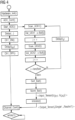
- the hardware is initialized Hardware_Init(). This involves setting the clock frequency and configuring the microcontroller's peripherals. Then, in step ADC_Conf(), the analog-digital converter is prepared for sampling the output voltages.
- the length of the buffer i.e. the number of memory locations j, is set, or the sampling time ts is determined. The configuration must be adjusted so that enough samples are collected during the test sequence for operational use. The number of samples n, or the buffer length j, must be the same as for the training data.
- the analog-digital converter is set so that the sampling of the data runs parallel to the main control process. This is made possible by direct memory access.
- the analog-digital converter is triggered Start_ADC().
- the sampling process of the analog-digital converter begins and runs parallel to the test sequence.
- the test sequence can optionally also start with a slight time delay in order to be able to take into account hardware-related conditions (Delay(%)).
- the channel is then switched on (Ch1_ON()) and after a switch-on time ton of typically a few 100 ⁇ s (Delay(ton)), channel 1 is switched off again (Ch1_OFF()).
- both output channels are monitored via the sampling process of the analog-digital converter.
- the first value of the output voltage of channel 1 is determined (Scan_UCh1()) and written to the first memory location of the buffer ( Val_UCh1 ⁇ Buf[ j ]), whereupon the memory location is increased (j++). Then the first The value of the output voltage of channel 2 is determined (Scan_UCh2()) and written into the second memory cell of the buffer (Val_UCh2 ⁇ Buf[ j ]). The memory address is then increased again (j++). This process is repeated until the buffer is completely full, with the sampling process taking place at the previously set sampling times ts (Delay(ts)).
- the data is processed. If the order of the values of the output voltage of channel 1 and channel 2 does not match the order in the training data, or if it is sampled on two different analog-digital converter peripherals, the data must be sorted (Sort_Buf()). This is followed by the same normalization as for the training data (Norm_Buf()). Since the values from the analog-digital converter are available as 10-bit integer values, normalization by 1024 is appropriate. With 12-bit resolution, the normalization factor would be 4096. After sorting and normalization, the input tensor is available so that the inference can be carried out. The result is the output tensor with the prediction of whether the channels are connected in parallel or not.
- the monitoring device can configure the channels (Channel_Conf()). This allows the parameters for parallel operation to be adjusted for the further course of the program. This includes in particular the current distribution of the channels, adjustment of the triggering characteristic, limitation times, and start-up behavior.
- the power supply device then starts up as follows, depending on the scenario: After channel 1 is switched on, the termination condition is checked as to whether the output voltage Uout has (almost) reached the value of the input voltage Uin (scenario a). The switch-on time is then monitored to prevent the transistor of channel 1 from becoming too hot, and it is checked whether a parallel connection of another channel has been detected. These queries are repeated until either the maximum duty cycle is reached (scenario b) and/or a parallel connection has been detected.
- the embodiments describe the use of the neural network for only two output channels. However, the invention can be applied without restrictions to applications with almost any number of channels.
- the method according to the invention can also be used during operation of a power supply device.
- the output current curves can also be used as data for the neural network instead of the voltage curves. If the current setpoint is changed briefly on a channel, either the output voltage and/or the output current serves as a detection signal for a parallel circuit.
- Fig.6 shows the operational sequence as a sequence within a program sequence in the source code of the ⁇ C. This can be a continuous part of the main program or a cyclically called auxiliary program. The process is started by triggering the analog-digital converter, whereby the scanning process of the analog-digital converter is carried out in parallel to the test sequence.
- the current in the channel is regulated back.
- the voltage at the output is then either reduced or the current is taken over by a channel connected in parallel.
- a neural network can now be trained in such a way that it can be recognized both by the voltage change at the output, provided this occurs on both channels, and by the current change in the channels.
- the setpoint of channel 1 is adjusted again and regular operation is restored.
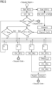
- the output voltage and/or the output current of both channels is monitored via the analog-digital converter.
- the first measured value of channel 1 is recorded (Scan_Val_Ch1()) and written to a buffer (Val_Ch1 ⁇ Buf[ j ]).
- the measured value on channel 2 is recorded (Scan-Val_Ch2()) and written to the buffer (Val_Ch2 ⁇ Buf[ j ]).
- the entire process is repeated at the sample rate ts (Delay(ts)) is repeated until the buffer is full.
- the measured values are then sorted (Sort_Buf()) and standardized (Norm_Buf) if necessary, after which the inference (Inference()) is carried out. If a parallel connection of the channels is detected, they are configured accordingly and the associated parameters are adjusted (Channel_Conf()).
- the presence of a parallel connection is not tested using a test sequence, but rather during the runtime of the program, using the measured values that are already determined.
Landscapes
- Engineering & Computer Science (AREA)
- Physics & Mathematics (AREA)
- Theoretical Computer Science (AREA)
- General Physics & Mathematics (AREA)
- General Health & Medical Sciences (AREA)
- General Engineering & Computer Science (AREA)
- Biophysics (AREA)
- Computational Linguistics (AREA)
- Data Mining & Analysis (AREA)
- Evolutionary Computation (AREA)
- Artificial Intelligence (AREA)
- Molecular Biology (AREA)
- Computing Systems (AREA)
- Biomedical Technology (AREA)
- Life Sciences & Earth Sciences (AREA)
- Mathematical Physics (AREA)
- Software Systems (AREA)
- Health & Medical Sciences (AREA)
- Power Engineering (AREA)
- Supply And Distribution Of Alternating Current (AREA)
- Measurement Of Current Or Voltage (AREA)
Priority Applications (4)
| Application Number | Priority Date | Filing Date | Title |
|---|---|---|---|
| EP22209307.2A EP4375680A1 (fr) | 2022-11-24 | 2022-11-24 | Procédé de détection de circuits parallèles dans des dispositifs d'alimentation électrique |
| CN202380091974.2A CN121219593A (zh) | 2022-11-24 | 2023-11-21 | 用于在供电装置中识别并联的方法 |
| PCT/EP2023/082599 WO2024110488A1 (fr) | 2022-11-24 | 2023-11-21 | Procédé de détection de circuits parallèles dans des dispositifs d'alimentation électrique |
| EP23820756.7A EP4605762A1 (fr) | 2022-11-24 | 2023-11-21 | Procédé de détection de circuits parallèles dans des dispositifs d'alimentation électrique |
Applications Claiming Priority (1)
| Application Number | Priority Date | Filing Date | Title |
|---|---|---|---|
| EP22209307.2A EP4375680A1 (fr) | 2022-11-24 | 2022-11-24 | Procédé de détection de circuits parallèles dans des dispositifs d'alimentation électrique |
Publications (1)
| Publication Number | Publication Date |
|---|---|
| EP4375680A1 true EP4375680A1 (fr) | 2024-05-29 |
Family
ID=84361834
Family Applications (2)
| Application Number | Title | Priority Date | Filing Date |
|---|---|---|---|
| EP22209307.2A Withdrawn EP4375680A1 (fr) | 2022-11-24 | 2022-11-24 | Procédé de détection de circuits parallèles dans des dispositifs d'alimentation électrique |
| EP23820756.7A Pending EP4605762A1 (fr) | 2022-11-24 | 2023-11-21 | Procédé de détection de circuits parallèles dans des dispositifs d'alimentation électrique |
Family Applications After (1)
| Application Number | Title | Priority Date | Filing Date |
|---|---|---|---|
| EP23820756.7A Pending EP4605762A1 (fr) | 2022-11-24 | 2023-11-21 | Procédé de détection de circuits parallèles dans des dispositifs d'alimentation électrique |
Country Status (3)
| Country | Link |
|---|---|
| EP (2) | EP4375680A1 (fr) |
| CN (1) | CN121219593A (fr) |
| WO (1) | WO2024110488A1 (fr) |
Cited By (1)
| Publication number | Priority date | Publication date | Assignee | Title |
|---|---|---|---|---|
| EP4675874A1 (fr) | 2024-07-05 | 2026-01-07 | Siemens Aktiengesellschaft | Équilibrage de charge de canaux de sortie connectés en parallèle d'un dispositif d'alimentation électrique |
Citations (7)
| Publication number | Priority date | Publication date | Assignee | Title |
|---|---|---|---|---|
| US5796631A (en) * | 1997-02-10 | 1998-08-18 | Tempo Instrument, Inc. | Method and apparatus for monitoring and characterizing power quality, faults and other phenomena in network power systems |
| JP2007028837A (ja) * | 2005-07-20 | 2007-02-01 | Fuji Electric Systems Co Ltd | 無停電電源装置の並列給電システム |
| EP2624398A1 (fr) * | 2012-02-06 | 2013-08-07 | Siemens Aktiengesellschaft | Alimentation en courant C.C./C.C. dotée de sorties commutables en parallèle |
| US20190138072A1 (en) * | 2017-11-08 | 2019-05-09 | Renesas Electronics Corporation | Power supply system and semiconductor device used for the same |
| US20200003659A1 (en) * | 2017-02-28 | 2020-01-02 | Green Running Limited | An appliance operation signal processing system and method |
| CN113131725A (zh) * | 2021-04-16 | 2021-07-16 | 安徽大学 | 一种基于碳化硅的智能功率模块及应用 |
| US20220255153A1 (en) * | 2019-10-02 | 2022-08-11 | Lg Energy Solution, Ltd. | Method and system for detecting connection fault of parallel connection cells |
-
2022
- 2022-11-24 EP EP22209307.2A patent/EP4375680A1/fr not_active Withdrawn
-
2023
- 2023-11-21 CN CN202380091974.2A patent/CN121219593A/zh active Pending
- 2023-11-21 WO PCT/EP2023/082599 patent/WO2024110488A1/fr not_active Ceased
- 2023-11-21 EP EP23820756.7A patent/EP4605762A1/fr active Pending
Patent Citations (8)
| Publication number | Priority date | Publication date | Assignee | Title |
|---|---|---|---|---|
| US5796631A (en) * | 1997-02-10 | 1998-08-18 | Tempo Instrument, Inc. | Method and apparatus for monitoring and characterizing power quality, faults and other phenomena in network power systems |
| JP2007028837A (ja) * | 2005-07-20 | 2007-02-01 | Fuji Electric Systems Co Ltd | 無停電電源装置の並列給電システム |
| EP2624398A1 (fr) * | 2012-02-06 | 2013-08-07 | Siemens Aktiengesellschaft | Alimentation en courant C.C./C.C. dotée de sorties commutables en parallèle |
| EP2812969B1 (fr) | 2012-02-06 | 2020-02-26 | Siemens Aktiengesellschaft | Alimentation en courant c.c./c.c. dotée de sorties commutables en parallèle |
| US20200003659A1 (en) * | 2017-02-28 | 2020-01-02 | Green Running Limited | An appliance operation signal processing system and method |
| US20190138072A1 (en) * | 2017-11-08 | 2019-05-09 | Renesas Electronics Corporation | Power supply system and semiconductor device used for the same |
| US20220255153A1 (en) * | 2019-10-02 | 2022-08-11 | Lg Energy Solution, Ltd. | Method and system for detecting connection fault of parallel connection cells |
| CN113131725A (zh) * | 2021-04-16 | 2021-07-16 | 安徽大学 | 一种基于碳化硅的智能功率模块及应用 |
Cited By (1)
| Publication number | Priority date | Publication date | Assignee | Title |
|---|---|---|---|---|
| EP4675874A1 (fr) | 2024-07-05 | 2026-01-07 | Siemens Aktiengesellschaft | Équilibrage de charge de canaux de sortie connectés en parallèle d'un dispositif d'alimentation électrique |
Also Published As
| Publication number | Publication date |
|---|---|
| CN121219593A (zh) | 2025-12-26 |
| EP4605762A1 (fr) | 2025-08-27 |
| WO2024110488A1 (fr) | 2024-05-30 |
Similar Documents
| Publication | Publication Date | Title |
|---|---|---|
| DE68929102T2 (de) | Lernverarbeitungssystem | |
| DE112022000106T5 (de) | Verfahren zur Getriebefehlerdiagnose und Signalerfassung, eine Vorrichtung und ein elektronisches Gerät | |
| DE69223787T2 (de) | System fuer qualitative schlussfolgerung mit paralleler verarbeitung | |
| EP2649567B1 (fr) | Procédée pour la modélisation sur ordinateur d'un système technique | |
| DE202017102238U1 (de) | Aktorsteuerungssystem | |
| DE202017102235U1 (de) | Trainingssystem | |
| DE102020117609A1 (de) | Verarbeitung von Zustandsdaten einer Batterie zur Alterungsschätzung | |
| DE102019217613A1 (de) | Verfahren zur diagnose eines motorzustands und diagnostisches modellierungsverfahren dafür | |
| AT513189A2 (de) | Verfahren zur Ermittlung eines regelungstechnischen Beobachters für den SoC | |
| DE60211520T2 (de) | Anordnung zur Steuerung des Betriebs eines physikalischen Systems wie zum Beispiel einer Brennstoffzelle in elektrischen Fahrzeugen | |
| DE69009786T2 (de) | Schaltungsanordnung mit Mehrfachrückkopplung. | |
| DE10245931A1 (de) | Workflow-Management-System und Verfahren mit kontinuierlicher Status-Verwaltung | |
| DE69607166T2 (de) | Elektronische Anordnung zur Durchführung von Konvolutionsoperationen | |
| WO2024110488A1 (fr) | Procédé de détection de circuits parallèles dans des dispositifs d'alimentation électrique | |
| EP1252566B1 (fr) | Configuration d'elements de calcul interconnectes et procede de determination assistee par ordinateur du deuxieme etat d'un systeme dans un premier espace d'etat a partir d'un premier etat du systeme dans le premier espace d'etat | |
| DE60202443T2 (de) | Methode zum Testen eines elektronischen Bauteils | |
| DE102023200854A1 (de) | Computerimplementiertes Verfahren zum Trainieren mindestens eines Vorhersagemodells | |
| DE102019213061A1 (de) | Klassifizierung von KI-Modulen | |
| DE19742448C1 (de) | Diagnosemodul zum Erstellen einer Diagnose für elektrisch ansteuerbare Systeme und Diagnoseeinrichtung zum Erstellen einer Gesamtsystemdiagnose | |
| DE102021212524A1 (de) | Verfahren zum Betreiben eines Sensors | |
| DE112018006331T5 (de) | Testfallgenerierungsvorrichtung, Testfallgenerierungsverfahren und Testfallgenerierungsprogramm | |
| DE112021008149T5 (de) | Verfahren und System zum Vorhersagen der Temperatur eines thermischen Systems | |
| DE102022134601A1 (de) | Systeme und verfahren für das training und die bereitstellung von modellen für maschinelles lernen | |
| WO2021063568A1 (fr) | Procédé d'identification de paramètres d'un modèle de boîte noire pour une ou plusieurs installations énergétiques dans un système énergétique | |
| DE102017104049B4 (de) | Verfahren und vorrichtung zum überprüfen der zuverlässigkeit eines chips |
Legal Events
| Date | Code | Title | Description |
|---|---|---|---|
| PUAI | Public reference made under article 153(3) epc to a published international application that has entered the european phase |
Free format text: ORIGINAL CODE: 0009012 |
|
| STAA | Information on the status of an ep patent application or granted ep patent |
Free format text: STATUS: THE APPLICATION HAS BEEN PUBLISHED |
|
| AK | Designated contracting states |
Kind code of ref document: A1 Designated state(s): AL AT BE BG CH CY CZ DE DK EE ES FI FR GB GR HR HU IE IS IT LI LT LU LV MC ME MK MT NL NO PL PT RO RS SE SI SK SM TR |
|
| STAA | Information on the status of an ep patent application or granted ep patent |
Free format text: STATUS: THE APPLICATION IS DEEMED TO BE WITHDRAWN |
|
| 18D | Application deemed to be withdrawn |
Effective date: 20241130 |