EP4375701A1 - Gerät zum scannen in der fmcw lidar abstandmessung - Google Patents
Gerät zum scannen in der fmcw lidar abstandmessung Download PDFInfo
- Publication number
- EP4375701A1 EP4375701A1 EP22208845.2A EP22208845A EP4375701A1 EP 4375701 A1 EP4375701 A1 EP 4375701A1 EP 22208845 A EP22208845 A EP 22208845A EP 4375701 A1 EP4375701 A1 EP 4375701A1
- Authority
- EP
- European Patent Office
- Prior art keywords
- light
- measuring light
- retroreflector
- optical system
- reflected
- Prior art date
- Legal status (The legal status is an assumption and is not a legal conclusion. Google has not performed a legal analysis and makes no representation as to the accuracy of the status listed.)
- Pending
Links
- 238000005259 measurement Methods 0.000 title claims abstract description 8
- 230000003287 optical effect Effects 0.000 claims abstract description 83
- 241000282326 Felis catus Species 0.000 claims abstract description 6
- 230000010287 polarization Effects 0.000 claims description 23
- 230000001419 dependent effect Effects 0.000 claims description 6
- 230000001681 protective effect Effects 0.000 claims description 4
- 239000011159 matrix material Substances 0.000 description 8
- 238000012545 processing Methods 0.000 description 6
- 210000001747 pupil Anatomy 0.000 description 5
- 238000013459 approach Methods 0.000 description 3
- 230000035559 beat frequency Effects 0.000 description 3
- 230000001902 propagating effect Effects 0.000 description 3
- 238000000926 separation method Methods 0.000 description 3
- 208000036758 Postinfectious cerebellitis Diseases 0.000 description 2
- 239000011521 glass Substances 0.000 description 2
- 238000004519 manufacturing process Methods 0.000 description 2
- 239000000758 substrate Substances 0.000 description 2
- GPXJNWSHGFTCBW-UHFFFAOYSA-N Indium phosphide Chemical compound [In]#P GPXJNWSHGFTCBW-UHFFFAOYSA-N 0.000 description 1
- 241001465754 Metazoa Species 0.000 description 1
- 229910052581 Si3N4 Inorganic materials 0.000 description 1
- XUIMIQQOPSSXEZ-UHFFFAOYSA-N Silicon Chemical compound [Si] XUIMIQQOPSSXEZ-UHFFFAOYSA-N 0.000 description 1
- 238000010521 absorption reaction Methods 0.000 description 1
- 230000021615 conjugation Effects 0.000 description 1
- 230000007423 decrease Effects 0.000 description 1
- 238000001514 detection method Methods 0.000 description 1
- 230000000694 effects Effects 0.000 description 1
- 239000013307 optical fiber Substances 0.000 description 1
- 230000000737 periodic effect Effects 0.000 description 1
- 238000012805 post-processing Methods 0.000 description 1
- 229910052710 silicon Inorganic materials 0.000 description 1
- 239000010703 silicon Substances 0.000 description 1
- HQVNEWCFYHHQES-UHFFFAOYSA-N silicon nitride Chemical compound N12[Si]34N5[Si]62N3[Si]51N64 HQVNEWCFYHHQES-UHFFFAOYSA-N 0.000 description 1
- 230000002123 temporal effect Effects 0.000 description 1
Images

Classifications
-
- G—PHYSICS
- G01—MEASURING; TESTING
- G01S—RADIO DIRECTION-FINDING; RADIO NAVIGATION; DETERMINING DISTANCE OR VELOCITY BY USE OF RADIO WAVES; LOCATING OR PRESENCE-DETECTING BY USE OF THE REFLECTION OR RERADIATION OF RADIO WAVES; ANALOGOUS ARRANGEMENTS USING OTHER WAVES
- G01S7/00—Details of systems according to groups G01S13/00, G01S15/00, G01S17/00
- G01S7/48—Details of systems according to groups G01S13/00, G01S15/00, G01S17/00 of systems according to group G01S17/00
- G01S7/481—Constructional features, e.g. arrangements of optical elements
- G01S7/4811—Constructional features, e.g. arrangements of optical elements common to transmitter and receiver
- G01S7/4812—Constructional features, e.g. arrangements of optical elements common to transmitter and receiver transmitted and received beams following a coaxial path
-
- G—PHYSICS
- G01—MEASURING; TESTING
- G01S—RADIO DIRECTION-FINDING; RADIO NAVIGATION; DETERMINING DISTANCE OR VELOCITY BY USE OF RADIO WAVES; LOCATING OR PRESENCE-DETECTING BY USE OF THE REFLECTION OR RERADIATION OF RADIO WAVES; ANALOGOUS ARRANGEMENTS USING OTHER WAVES
- G01S17/00—Systems using the reflection or reradiation of electromagnetic waves other than radio waves, e.g. lidar systems
- G01S17/02—Systems using the reflection of electromagnetic waves other than radio waves
- G01S17/06—Systems determining position data of a target
- G01S17/08—Systems determining position data of a target for measuring distance only
- G01S17/32—Systems determining position data of a target for measuring distance only using transmission of continuous waves, whether amplitude-, frequency-, or phase-modulated, or unmodulated
- G01S17/34—Systems determining position data of a target for measuring distance only using transmission of continuous waves, whether amplitude-, frequency-, or phase-modulated, or unmodulated using transmission of continuous, frequency-modulated waves while heterodyning the received signal, or a signal derived therefrom, with a locally-generated signal related to the contemporaneously transmitted signal
-
- G—PHYSICS
- G01—MEASURING; TESTING
- G01S—RADIO DIRECTION-FINDING; RADIO NAVIGATION; DETERMINING DISTANCE OR VELOCITY BY USE OF RADIO WAVES; LOCATING OR PRESENCE-DETECTING BY USE OF THE REFLECTION OR RERADIATION OF RADIO WAVES; ANALOGOUS ARRANGEMENTS USING OTHER WAVES
- G01S7/00—Details of systems according to groups G01S13/00, G01S15/00, G01S17/00
- G01S7/48—Details of systems according to groups G01S13/00, G01S15/00, G01S17/00 of systems according to group G01S17/00
- G01S7/491—Details of non-pulse systems
- G01S7/4912—Receivers
- G01S7/4917—Receivers superposing optical signals in a photodetector, e.g. optical heterodyne detection
-
- G—PHYSICS
- G01—MEASURING; TESTING
- G01S—RADIO DIRECTION-FINDING; RADIO NAVIGATION; DETERMINING DISTANCE OR VELOCITY BY USE OF RADIO WAVES; LOCATING OR PRESENCE-DETECTING BY USE OF THE REFLECTION OR RERADIATION OF RADIO WAVES; ANALOGOUS ARRANGEMENTS USING OTHER WAVES
- G01S7/00—Details of systems according to groups G01S13/00, G01S15/00, G01S17/00
- G01S7/48—Details of systems according to groups G01S13/00, G01S15/00, G01S17/00 of systems according to group G01S17/00
- G01S7/481—Constructional features, e.g. arrangements of optical elements
- G01S7/4817—Constructional features, e.g. arrangements of optical elements relating to scanning
Definitions
- the invention relates to a device for scanning range - and preferably also velocity - measurement relative to a moving or unmoving object based on FMCW LiDAR technology.
- Such devices can be used, for example, in autonomously driving vehicles and may be implemented - at least to some extent - as photonic integrated circuits (PIC) that do not contain any moving parts.
- PIC photonic integrated circuits
- FMCW Frequency-modulated continuous wave
- frequency-modulated light beams scan the environment. A small fraction of the light, which was diffusely reflected at an object, is received and superimposed with a local oscillator wave. The frequency difference between the two signals, which is usually referred to as beat frequency, is measured and used to compute the range of the object.
- beat frequency By using a tunable laser as light source and a photodiode as detector, the beat frequency can be extracted directly from the photodiode current, because the photodiode delivers a current that is proportional to the squared sum of the two optical waves ("self-mixing effect"). If the Doppler shift is taken into account, the relative velocity between the scanning device and the object along the light propagation direction can be calculated, too.
- Scanning devices based on this measurement principle have to be very robust and reliable if they are to be used in vehicles. This is true in particular if the vehicles drive autonomously, since the safety in autonomous driving decisively depends on the scanning device that is used to generate a three-dimensional profile of the environment. Scanning devices which are implemented as photonic integrated circuits (PIC) do not require moving components. This makes them potentially more reliable than scanning devices with moving mirrors, and thus particularly suitable for applications in vehicles.
- PIC photonic integrated circuits
- Such PIC scanning devices are disclosed, for example, in WO 2021/239408 A1 .
- These devices may include a distribution matrix comprising a plurality of optical switches that are arranged in a tree-like manner.
- the distribution matrix distributes the optical signals among different free space couplers that emit the optical signal into free space.
- the free space couplers are arranged in a front focal plane of a collimating optical system that directs the optical signals optical waveguides into various directions.
- FMCW LiDAR scanning devices for applications in vehicles require a high spatial resolution so that also small objects can be detected even at large distances.
- the available spatial resolution corresponds to the number of free space couplers or optical channels, which is equivalent to the number of pixels on a screen after post-processing. It can be shown that in the horizontal direction the number of optical channels should be at least in the order of 1.000, while in the vertical direction a smaller resolution often suffices.
- a device for scanning FMCW LiDAR range measurement comprising a light source configured to produce light having a varying frequency, a collimating optical system having a front focal plane, and a plurality of emitters that are configured to emit the light produced by the light source as measuring light.
- the emitters are arranged in a plane that coincides with the front focal plane or is optically conjugate to the front focal plane.
- the device further comprises a retroreflector that is arranged behind the collimating optical system in a light path of the emitted measuring light, and a plurality of receivers that are configured to receive (a) a first portion of the measuring light that has been emitted by an associated emitter and reflected from an external object and (b) a second portion of the measuring light that has been emitted by the associated emitter and reflected from the retroreflector.
- At least one detector is configured to detect a superposition of the first and the second portion of the measuring light.
- a calculation unit is configured to determine the range to the external object from the superposition detected by the detector.
- the invention is based on the insight that the PIC-internal distribution of the local oscillator wave significantly contributes to the complexity of the PIC.
- an optical waveguide which connects the light source with the detector of the respective channel, is required for each optical channel.
- the invention takes a different approach, because the local oscillator wave is not created internally in the PIC by splitting off a portion of the light produced by the light source, but by reflecting a small portion (usually only a few percent of the total intensity) of the measuring light after it has left the PIC and passed the collimating optical system.
- the measuring light was reflected by a simple reflecting element having a plane or curved reflecting surface, it would generally be reflected into a different direction and could not be easily received and guided back to the respective detector.
- a retroreflector By using a retroreflector, however, the light forming the oscillator wave will be reflected back in the same direction from which it originated.
- the collimating optical system then ensures that this retro-reflected portion of the measuring light enters the receiver that is associated with the emitter.
- a receiver is referred to as being associated with an emitter if it receives (only) the (retro-)reflected portions of measuring light that was emitted by this particular emitter.
- each receiver and its associated emitter are not structurally distinct, but are formed by the same photonic element.
- This photonic element is usually a free-space coupler that couples light guided in an optical waveguide into free space and - in the opposite direction - light propagating in free spaces into the optical waveguide.
- Such a configuration which is often referred to as monostatic, has the advantage that only one free-space coupler forming the emitter and simultaneously the receiver is required for each optical channel.
- a disadvantage of monostatic designs is that the received measuring light has to be separated from the signal path inside the PIC, which is usually achieved by providing an optical circulator.
- optical circulators which often rely on the principle of polarization splitting, are complex components that increase the PIC complexity significantly.
- each receiver and its associated emitter are formed by different photonic elements.
- the signal separation can be performed outside the PIC, for example using bulk birefringent plates, wave-plates and Faraday rotators. These bulk components are commonly used by all optical channels and help to reduce the complexity of the PIC layout.
- the photonic elements forming the receivers and the associated emitters are arranged either immediately adjacent to each other or in an interleaved fashion, as this is known as such from US 2021/0316756 A1 .
- the different photonic elements forming the emitters and the receivers may be arranged at optically conjugate positions.
- the device may comprise a polarization dependent beam splitter that is arranged in a light path of the measuring light between the collimating optical system and the receivers.
- a quarter-wave plate may then be arranged in a light path of the measuring light between the optical collimating system and the retroreflector.
- Such a configuration makes it possible to guide all the reflected light towards the receivers in a very efficient manner, because only simple bulk optical components such as a polarization dependent beam splitter and a quarter-wave plate are required.
- the emitted measuring light being in a linear state of polarization will be transformed into a circular state of polarization when passing the quarter-wave plate.
- the light reflected from the external object or the retroreflector passes again the quarter-wave plate that transforms the circular state of polarization back into a linear state of polarization that is orthogonal to the original linear state of polarization.
- the polarization dependent beam splitter passes or reflects the light depending on its state of polarization.
- the retroreflector should be able to preserve the state of polarization.
- this ability is generally, i.e. also in the absence of polarization control, advantageous, because it ensures better interference with the first portion of the measuring light that has been reflected from the external object.
- a cat's eye reflector is particularly suitable for the present invention because this type of retroreflector perfectly maintains the state of polarization.
- Most other available retroreflectors e.g. corner reflectors comprising a set of three mutually perpendicular reflective surfaces, do not maintain the state of polarization.
- the device may comprise a transparent optical element having no refractive power that supports the retroreflector. Since the retroreflector is arranged in the light path of the measuring light, it inevitably reduces the intensity of the measuring light that will ultimately impinge on the external object. Any structure that supports the retroreflector may also impede the propagation of the measuring light. By using as supporting structure a transparent optical element with no refractive power, e.g., a glass plate or a wedge, no additional light losses occur.
- the transparent optical element may be a protective window through which the measuring light leaves the device. Most devices comprise such a window so that no additional support structure is required.
- the retroreflector may be supported by one or more elongated elements that are so thin that they add little to the absorption of the measuring light.
- the retroreflector is arranged in a back focal plane of the collimating optical system. Since the back focal plane is a pupil plane of the collimating optical system, the measuring light beams emitted from all the emitters completely overlap. Thus, it is possible to retro-reflect a portion of measuring light emitted from any of the emitters with only one retroreflector.
- This retroreflector may be arranged at a position close to the circumference of the measuring light beams' profile. Such a position is advantageous, because the measuring light beams typically have a Gaussian intensity profile. Even if the retroreflector is comparatively large, the position at the circumference ensures that only a small portion of the measuring light is retro-reflected.
- the retroreflector may be arranged on the optical axis of the collimating optical system. At this position the measuring light beams have their maximum intensity. However, if the diameter of the retroreflector is sufficiently small, the amount of retro-reflected measuring light can nevertheless be kept small enough.
- the device may comprise not only one, but a plurality of retroreflectors that are arranged on a line that delimits a field of view of the device. More than one retroreflectors are required in this embodiment because - unless the retroreflectors are arranged in the pupil plane - there is generally no position on this line at which all measuring light beams propagating along different directions overlap. Positioning the retroreflectors outside the pupil plane of the collimating optical system is often advantageous with a view to the longitudinal dimensions of the device.
- Figure 1 is a schematic side view of a vehicle 10 approaching an object 12 that is represented by a tree.
- the vehicle 10 has at least one scanning device 14 that uses light beams L11, L21, L31 and L41 to scan the environment ahead of the vehicle 10. Based on the distance information generated by the scanning device 14, a three-dimensional image of the environment is calculated. In addition, the scanning device 14 determines the relative speed to the object 12. This information is particularly important if the object 12 is another vehicle, an animal or a pedestrian that is also moving.
- the scanning device 14 emits light beams L11 to L41 in different directions in a vertical plane (in Figure 1 this is the paper plane) in order to scan the environment in a vertical direction. Scanning takes place also in a horizontal direction, as this is shown in Figure 2 which is a top view on the scanning device 14.
- Four light beams L11, L12, L13 and L14 are shown which are emitted in different directions in a horizontal plane.
- FIG. 3 schematically shows the basic design of the scanning device 14 according to a first embodiment of the invention.
- the scanning device 14 is designed as a LiDAR system and comprises an FMCW light source 16 that produces light.
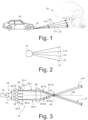
- the light produced by the light source 16 has a frequency f that varies ("chirps") periodically over time t between a lower frequency f l and a higher frequency f h .
- Each measurement interval with a chirp duration T is divided into two halves of equal length T/2.
- the frequency f decreases linearly with a constant negative downchirp rate - r chirp .
- the frequency of the light can thus be described by a periodic triangular function. However, other functional relationships are also contemplated, e.g., sawtooth functions.
- the light source 16 is connected to a switch matrix 22 comprising a plurality of optical switches 21 that may be configured as thermo-optical switches, for example.
- the switch matrix 22 distributes the light among four optical channels 23-1 to 23-4.
- Each optical channel 23-1 to 23-4 comprises a processing unit 24 that will be described in further detail below with reference to Figure 5 .
- Each processing unit 24 has a light input 26 connected to the switch matrix 22 and a light output 28 connected to an optical waveguide 30 that terminates at a free space coupler 32-1 to 32-4.
- the free space couplers 32-1 to 32-4 may be formed by an edge or a grating coupler, for example, as this in known in the art as such.
- the free space couplers 32-1 to 32-4 are also referred to as emitters and receivers.
- the free space couplers 32-1 to 32-4 form emitters, because they emit - subsequently or simultaneously, but individually for each optical channel 23-1 to 23-4 - light produced by the light source 16 as measuring light.
- Two diverging measuring light bundles 34-1 and 34-4 emitted by the emitters 32-1 and 32-4, respectively, are shown in Figure 3 for the sake of illustration.
- the free space couplers 32-1 to 32-4 form also receivers, because they receive measuring light that has been reflected, as this will be explained in more detail below.
- a collimating optical system 36 is arranged in a light path of the measuring light.
- the collimating optical system is represented in Figure 3 by a single lens element only, but may comprise more than one lens and/or other optical elements.
- the collimating optical system has a front focal plane 38 in which the emitters 32-1 to 32-4 are arranged.
- the term "plane” shall be construed broadly, because it may not be perfectly planar, but slightly curved.
- the diverging measuring light bundles 34-1 and 34-4 are collimated by the collimating optical system, as this is shown in Figure 3 .
- the angle of the collimated measuring light beams 34-1 and 34-4 relative to an optical axis OA of the collimating optical system depends on the distance of the emitter 32-1 to 32-4, which emits the respective measuring light beam 34-1 or 34-4, from the optical axis OA. Therefore, the scanning device 14 is able to direct, either subsequently or simultaneously, measuring light beams 34-1 and 34-4 into different directions, thereby scanning the environment.
- the emitted collimated measuring light beams 34-1 and 34-4 are to some extent diffusely reflected at an external object such as the object 12 shown in Figure 1 .
- a small portion of the reflected measuring light returns to the scanning device 14. Only a first portion 34-1a, 34-4a of the diffusely reflected measuring light that propagates anti-parallel to the collimated measuring light beams 34-1 and 34-4 is able to enter the respective free space coupler 32-1 to 32-4 that now has the function of a receiver.
- the processing of the reflected light received by the receivers 32-1 to 32-4 will be explained in more detail below with reference to Figure 5 .
- the collimating optical system 36 has a back focal plane 40 which is a pupil plane of the collimating optical system 36.
- a retroreflector 42 is arranged coaxially with the optical axis OA.
- the retroreflector 42 retro-reflects a second portion 34-1b, 34-4b of the measuring light, which impinges on the retroreflector 42.
- the retro-reflected measuring light 34-1b, 34-4b propagates anti-parallel to the collimated measuring light beams 34-1 and 34-4 and is thus able to enter the respective receiver 34-1 and 34-4 from which it originated.
- the free space coupler 32-1 emits a measuring light beam 34-1 from which a first portion 34-1a is reflected by the external object 12 anti-parallel to the scan direction, i.e., the direction of the collimated measuring light beam 34-1.
- a second portion 34-1b of the measuring light beam 34-1 is reflected at the fixed retroreflector 42 - again anti-parallel to the scan direction.
- both reflected portions of the measuring light propagate anti-parallel to the scan direction and are focused by the collimating optical system 36 on the free space coupler 32-1 working now as a receiver.
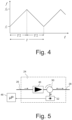
- FIG. 5 illustrates schematically the main components of one of the processing units 24.
- Light produced by the light source 16 and input at the light input 26 is amplified in an amplifier 46.
- the processing unit 24 further comprises an optical circulator 50 that passes the amplified light to the light exit 28.
- Received light that enters the light exit 28 is separated from the light path by the optical circulator 50 and guided towards a detector 52 that may be realized as a photodiode.
- the received light includes a first portion 34-1a to 34-4a and a second portion 34-1b to 34-4b that has been reflected from the external object 12 and the retroreflector 42, respectively.
- the detector 52 thus detects a superposition of the first portion 34-1a to 34-4a and the second portion 34-1b to 34-4b of the respective reflected measuring light 34-1 to 34-4.
- a calculation unit which may be part of the device control unit 48, then calculates the distance R and the relative radial velocity ⁇ to the object 12 on the basis of the detected beat frequency.
- the second portion 34-1b to 34-4b of the reflected measuring light therefore serves as local oscillator wave.
- no additional optical waveguides are required to guide a portion of the produced light directly from by the light source 16 towards the detectors 52 of the processing units 24.
- Selecting individual optical channels for emitting measuring light may alternatively accomplished by using a matrix of optical switches, as this is known in the art as such, see, for example, WO 2021/239408 A1 that was mentioned at the outset.
- a matrix of optical switches comprises a plurality of optical switches that are arranged in a tree-like manner and can be individually controlled.
- the measuring light bundles leave the PIC perpendicularly or at an angle ⁇ 90° to the plane of the PIC substrate.
- the collimating optical system 36 then has an optical axis OA that is also perpendicular or inclined to this plane.
- Beam steering in vertical planes may be accomplished by a mechanical scanner comprising a rotating or oscillating mirror or prism.
- a mechanical scanner comprising a rotating or oscillating mirror or prism.
- several PICs each representing a different emission plane are stacked one above the other so that the free space couplers 32-1 to 32-4 do not form a line, but a two-dimensional array. In this case no mechanical scanner for the second scan direction is required.
- FIG. 6 schematically illustrates a scanning device 14 according to a second embodiment.
- the scanning device has a housing 54 comprising a protective window 56 that is formed by a transparent plate and through which the measuring light leaves and - after reflection from an external object 12 - enters the scanning device 14.
- the inner side 57 of the protective window 56 supports a plurality of retroreflectors 42 that are arranged outside the pupil plane of the collimating optical system 36 and on a line that delimits the field of view (FOV) of the scanning device 14.
- FOV field of view
- This arrangement ensures that all the measuring light beams propagating along the different scan directions will be incident on at least one retroreflector 42 before they leave the scanning device 14. Since the measuring light beams typically have a Gaussian intensity profile, only a small fraction of the total intensity is retro-reflected, because the measuring light beams "touch" the retroreflectors 42 with their low intensity circumference.
- the scanning device 14 shown in Figure 6 is an example of a bi-static configuration in which there are separate emitters and receivers. More specifically, emitters denoted by 32-1' to 32-4' are arranged on a common transmitter PIC that is connected to the light source 16 and includes a switch matrix 22 and amplifiers 46 in each optical channel 23-1 to 23-4. Receivers 32-1" to 32-4" are arranged on a common receiver PIC that includes a detector 52 for each optical channel 23-1 to 23-4. As in the first embodiment, the emitters 32-1' to 32-4' and the receivers 32-1" to 32-4" are formed by free space couplers.
- the emitters 32-1' to 32-4' and the receivers 32-1" to 32-4" are arranged at optically conjugate positions. In this embodiment this is achieved by arranging the receivers 32-1" to 32-4" at a mirrored front focal plane 38' of the collimating optical system 36. As a result of the optical conjugation, measuring light that was emitted by the emitter 32-1' and reflected either at the external object 12 or at one of the retroreflectors 42 will be focused by the collimating optical system 36 on the associated receiver 32-1".
- the measuring light reflected from the external object 12 and the retroreflectors 42 is separated from the light path by a polarization dependent beam splitter 60 having a splitting plane that is inclined at an angle of 45° relative to the optical axis OA of the collimating optical system 36.
- a quarter-wave plate 62 which is arranged in a light path of the measuring light between the optical collimating system 36 and the retroreflectors 42, transforms the TE state of polarization (SOP) of the emitted measuring light into a circular SOP.
- the measuring light After being reflected at the external object 12 or the internal retroreflectors 42, the measuring light passes the quarter-wave plate 62 again. The latter transforms the circular SOP of the reflected light into a TM SOP. Due to the now orthogonal SOP, the polarization dependent beam splitter 60 reflects the converging light bundle by 90° towards the receiver PIC, where it couples into the associated receiver 32-1" to 32-4".
- the separation of the reflected light from the emission light path relies on the control of the state of polarization. For that reason, the retroreflectors 42 must maintain the state of polarization. Conventional corner retroreflectors do not have this property.
- FIG 7 illustrates a cat's eye retroreflector 42 that maintains the state of polarization and can therefore be used in the second embodiment shown in Figure 6 .
- the cat's eye retroreflector 42 comprises a rotationally symmetric glass body 64 having a spherically curved front surface 66 forming a lens, and a reflecting rear surface 68 that is also spherically curved and forms a mirror. Both surfaces 66, 68 have the same center of curvature 70.
- the collimated light entering the front surface 66 is focused on the rear surface 68 and is retro-reflected as collimated light.
- the collimating optical system 36 and a mechanical scanner are arranged on one or more photonic substrates.
- the embodiments disclosed herein can be realized using any integrated photonic platform, e.g. silicon, silicon nitride or indium phosphide. However, it may also be envisaged to have only some of these components integrated in the PIC, while others are connected to the PIC via an optical fiber.
Landscapes
- Engineering & Computer Science (AREA)
- Physics & Mathematics (AREA)
- Computer Networks & Wireless Communication (AREA)
- General Physics & Mathematics (AREA)
- Radar, Positioning & Navigation (AREA)
- Remote Sensing (AREA)
- Electromagnetism (AREA)
- Optical Radar Systems And Details Thereof (AREA)
Priority Applications (1)
| Application Number | Priority Date | Filing Date | Title |
|---|---|---|---|
| EP22208845.2A EP4375701A1 (de) | 2022-11-22 | 2022-11-22 | Gerät zum scannen in der fmcw lidar abstandmessung |
Applications Claiming Priority (1)
| Application Number | Priority Date | Filing Date | Title |
|---|---|---|---|
| EP22208845.2A EP4375701A1 (de) | 2022-11-22 | 2022-11-22 | Gerät zum scannen in der fmcw lidar abstandmessung |
Publications (1)
| Publication Number | Publication Date |
|---|---|
| EP4375701A1 true EP4375701A1 (de) | 2024-05-29 |
Family
ID=84361739
Family Applications (1)
| Application Number | Title | Priority Date | Filing Date |
|---|---|---|---|
| EP22208845.2A Pending EP4375701A1 (de) | 2022-11-22 | 2022-11-22 | Gerät zum scannen in der fmcw lidar abstandmessung |
Country Status (1)
| Country | Link |
|---|---|
| EP (1) | EP4375701A1 (de) |
Cited By (1)
| Publication number | Priority date | Publication date | Assignee | Title |
|---|---|---|---|---|
| DE102024131467A1 (de) * | 2024-10-29 | 2026-04-30 | Sick Ag | Optoelektronischer sensor zum erfassen von objekten |
Citations (4)
| Publication number | Priority date | Publication date | Assignee | Title |
|---|---|---|---|---|
| US5114226A (en) * | 1987-03-20 | 1992-05-19 | Digital Optronics Corporation | 3-Dimensional vision system utilizing coherent optical detection |
| US20150355327A1 (en) * | 2012-11-21 | 2015-12-10 | Nikon Metrology Nv | Scan mirrors for laser radar |
| US20210316756A1 (en) | 2020-04-14 | 2021-10-14 | Scantinel Photonics GmbH | Device and method for scanning measurement of the distance to an object |
| WO2021239408A1 (de) | 2020-05-25 | 2021-12-02 | Scantinel Photonics GmbH | Vorrichtung und verfahren zur scannenden messung des abstands zu einem objekt |
-
2022
- 2022-11-22 EP EP22208845.2A patent/EP4375701A1/de active Pending
Patent Citations (4)
| Publication number | Priority date | Publication date | Assignee | Title |
|---|---|---|---|---|
| US5114226A (en) * | 1987-03-20 | 1992-05-19 | Digital Optronics Corporation | 3-Dimensional vision system utilizing coherent optical detection |
| US20150355327A1 (en) * | 2012-11-21 | 2015-12-10 | Nikon Metrology Nv | Scan mirrors for laser radar |
| US20210316756A1 (en) | 2020-04-14 | 2021-10-14 | Scantinel Photonics GmbH | Device and method for scanning measurement of the distance to an object |
| WO2021239408A1 (de) | 2020-05-25 | 2021-12-02 | Scantinel Photonics GmbH | Vorrichtung und verfahren zur scannenden messung des abstands zu einem objekt |
Cited By (1)
| Publication number | Priority date | Publication date | Assignee | Title |
|---|---|---|---|---|
| DE102024131467A1 (de) * | 2024-10-29 | 2026-04-30 | Sick Ag | Optoelektronischer sensor zum erfassen von objekten |
Similar Documents
| Publication | Publication Date | Title |
|---|---|---|
| EP3987304B1 (de) | Lidar-system mit festkörperspektralabtastung | |
| US12377877B2 (en) | Device and method for scanning measurement of the distance to an object | |
| KR102628929B1 (ko) | 모드 필드 확장기를 갖는 lidar 시스템 | |
| KR102635962B1 (ko) | 다중-모드 도파관 광검출기를 갖는 lidar 시스템 | |
| EP3867663B1 (de) | Descan-kompensierung in abtastendem lidar | |
| US20170261612A1 (en) | Optical distance measuring system and light ranging method | |
| EP4075192A1 (de) | Vorrichtung und verfahren zur abtastung einer fmcw-lidarentfernungsmessung | |
| US12111396B2 (en) | Device and method for scanning frequency-modulated continuous wave (FMCW) LiDAR range measurement | |
| EP4375701A1 (de) | Gerät zum scannen in der fmcw lidar abstandmessung | |
| EP4375702A1 (de) | Vorrichtung zur abtastung einer fmcw-lidar-entfernungsmessung | |
| US12613340B2 (en) | Device for scanning frequency-modulated continuous wave (FMCW) LiDAR range measurement | |
| US20260126527A1 (en) | Optical module, lidar, and terminal | |
| US20250251512A1 (en) | Device and Method for Scanning Range Measurement | |
| KR20250026031A (ko) | 다채널 fmcw 라이다 시스템 |
Legal Events
| Date | Code | Title | Description |
|---|---|---|---|
| PUAI | Public reference made under article 153(3) epc to a published international application that has entered the european phase |
Free format text: ORIGINAL CODE: 0009012 |
|
| STAA | Information on the status of an ep patent application or granted ep patent |
Free format text: STATUS: THE APPLICATION HAS BEEN PUBLISHED |
|
| AK | Designated contracting states |
Kind code of ref document: A1 Designated state(s): AL AT BE BG CH CY CZ DE DK EE ES FI FR GB GR HR HU IE IS IT LI LT LU LV MC ME MK MT NL NO PL PT RO RS SE SI SK SM TR |
|
| STAA | Information on the status of an ep patent application or granted ep patent |
Free format text: STATUS: REQUEST FOR EXAMINATION WAS MADE |
|
| 17P | Request for examination filed |
Effective date: 20240801 |
|
| RBV | Designated contracting states (corrected) |
Designated state(s): AL AT BE BG CH CY CZ DE DK EE ES FI FR GB GR HR HU IE IS IT LI LT LU LV MC ME MK MT NL NO PL PT RO RS SE SI SK SM TR |