EP4376140A1 - Rouleau de gelée doté d'une propriété d'imprégnation d'électrolyte améliorée, et élément de batterie cylindrique, bloc-batterie et véhicule le comprenant - Google Patents
Rouleau de gelée doté d'une propriété d'imprégnation d'électrolyte améliorée, et élément de batterie cylindrique, bloc-batterie et véhicule le comprenant Download PDFInfo
- Publication number
- EP4376140A1 EP4376140A1 EP22893087.1A EP22893087A EP4376140A1 EP 4376140 A1 EP4376140 A1 EP 4376140A1 EP 22893087 A EP22893087 A EP 22893087A EP 4376140 A1 EP4376140 A1 EP 4376140A1
- Authority
- EP
- European Patent Office
- Prior art keywords
- roll
- jelly
- electrode
- elly
- slits
- Prior art date
- Legal status (The legal status is an assumption and is not a legal conclusion. Google has not performed a legal analysis and makes no representation as to the accuracy of the status listed.)
- Pending
Links
Images


Classifications
-
- H—ELECTRICITY
- H01—ELECTRIC ELEMENTS
- H01M—PROCESSES OR MEANS, e.g. BATTERIES, FOR THE DIRECT CONVERSION OF CHEMICAL ENERGY INTO ELECTRICAL ENERGY
- H01M10/00—Secondary cells; Manufacture thereof
- H01M10/04—Construction or manufacture in general
- H01M10/0431—Cells with wound or folded electrodes
-
- H—ELECTRICITY
- H01—ELECTRIC ELEMENTS
- H01M—PROCESSES OR MEANS, e.g. BATTERIES, FOR THE DIRECT CONVERSION OF CHEMICAL ENERGY INTO ELECTRICAL ENERGY
- H01M50/00—Constructional details or processes of manufacture of the non-active parts of electrochemical cells other than fuel cells, e.g. hybrid cells
- H01M50/50—Current conducting connections for cells or batteries
- H01M50/531—Electrode connections inside a battery casing
- H01M50/538—Connection of several leads or tabs of wound or folded electrode stacks
-
- B—PERFORMING OPERATIONS; TRANSPORTING
- B60—VEHICLES IN GENERAL
- B60L—PROPULSION OF ELECTRICALLY-PROPELLED VEHICLES; SUPPLYING ELECTRIC POWER FOR AUXILIARY EQUIPMENT OF ELECTRICALLY-PROPELLED VEHICLES; ELECTRODYNAMIC BRAKE SYSTEMS FOR VEHICLES IN GENERAL; MAGNETIC SUSPENSION OR LEVITATION FOR VEHICLES; MONITORING OPERATING VARIABLES OF ELECTRICALLY-PROPELLED VEHICLES; ELECTRIC SAFETY DEVICES FOR ELECTRICALLY-PROPELLED VEHICLES
- B60L50/00—Electric propulsion with power supplied within the vehicle
- B60L50/50—Electric propulsion with power supplied within the vehicle using propulsion power supplied by batteries or fuel cells
- B60L50/60—Electric propulsion with power supplied within the vehicle using propulsion power supplied by batteries or fuel cells using power supplied by batteries
- B60L50/64—Constructional details of batteries specially adapted for electric vehicles
-
- H—ELECTRICITY
- H01—ELECTRIC ELEMENTS
- H01M—PROCESSES OR MEANS, e.g. BATTERIES, FOR THE DIRECT CONVERSION OF CHEMICAL ENERGY INTO ELECTRICAL ENERGY
- H01M10/00—Secondary cells; Manufacture thereof
- H01M10/05—Accumulators with non-aqueous electrolyte
- H01M10/058—Construction or manufacture
- H01M10/0587—Construction or manufacture of accumulators having only wound construction elements, i.e. wound positive electrodes, wound negative electrodes and wound separators
-
- H—ELECTRICITY
- H01—ELECTRIC ELEMENTS
- H01M—PROCESSES OR MEANS, e.g. BATTERIES, FOR THE DIRECT CONVERSION OF CHEMICAL ENERGY INTO ELECTRICAL ENERGY
- H01M50/00—Constructional details or processes of manufacture of the non-active parts of electrochemical cells other than fuel cells, e.g. hybrid cells
- H01M50/50—Current conducting connections for cells or batteries
- H01M50/531—Electrode connections inside a battery casing
- H01M50/533—Electrode connections inside a battery casing characterised by the shape of the leads or tabs
-
- H—ELECTRICITY
- H01—ELECTRIC ELEMENTS
- H01M—PROCESSES OR MEANS, e.g. BATTERIES, FOR THE DIRECT CONVERSION OF CHEMICAL ENERGY INTO ELECTRICAL ENERGY
- H01M2220/00—Batteries for particular applications
- H01M2220/20—Batteries in motive systems, e.g. vehicle, ship, plane
-
- H—ELECTRICITY
- H01—ELECTRIC ELEMENTS
- H01M—PROCESSES OR MEANS, e.g. BATTERIES, FOR THE DIRECT CONVERSION OF CHEMICAL ENERGY INTO ELECTRICAL ENERGY
- H01M50/00—Constructional details or processes of manufacture of the non-active parts of electrochemical cells other than fuel cells, e.g. hybrid cells
- H01M50/10—Primary casings; Jackets or wrappings
- H01M50/102—Primary casings; Jackets or wrappings characterised by their shape or physical structure
- H01M50/107—Primary casings; Jackets or wrappings characterised by their shape or physical structure having curved cross-section, e.g. round or elliptic
-
- Y—GENERAL TAGGING OF NEW TECHNOLOGICAL DEVELOPMENTS; GENERAL TAGGING OF CROSS-SECTIONAL TECHNOLOGIES SPANNING OVER SEVERAL SECTIONS OF THE IPC; TECHNICAL SUBJECTS COVERED BY FORMER USPC CROSS-REFERENCE ART COLLECTIONS [XRACs] AND DIGESTS
- Y02—TECHNOLOGIES OR APPLICATIONS FOR MITIGATION OR ADAPTATION AGAINST CLIMATE CHANGE
- Y02E—REDUCTION OF GREENHOUSE GAS [GHG] EMISSIONS, RELATED TO ENERGY GENERATION, TRANSMISSION OR DISTRIBUTION
- Y02E60/00—Enabling technologies; Technologies with a potential or indirect contribution to GHG emissions mitigation
- Y02E60/10—Energy storage using batteries
-
- Y—GENERAL TAGGING OF NEW TECHNOLOGICAL DEVELOPMENTS; GENERAL TAGGING OF CROSS-SECTIONAL TECHNOLOGIES SPANNING OVER SEVERAL SECTIONS OF THE IPC; TECHNICAL SUBJECTS COVERED BY FORMER USPC CROSS-REFERENCE ART COLLECTIONS [XRACs] AND DIGESTS
- Y02—TECHNOLOGIES OR APPLICATIONS FOR MITIGATION OR ADAPTATION AGAINST CLIMATE CHANGE
- Y02P—CLIMATE CHANGE MITIGATION TECHNOLOGIES IN THE PRODUCTION OR PROCESSING OF GOODS
- Y02P70/00—Climate change mitigation technologies in the production process for final industrial or consumer products
- Y02P70/50—Manufacturing or production processes characterised by the final manufactured product
Definitions
- the present disclosure relates to a jelly-roll with an improved electrolyte impregnation property, and a cylindrical battery cell, a battery pack and a vehicle including the same.
- Types of secondary batteries currently widely used include lithium-ion batteries, lithium polymer batteries, nickel cadmium batteries, nickel hydrogen batteries, nickel zinc batteries, and the like.
- a unit secondary battery cell that is, a unit battery cell, has an operating voltage of about 2.5 V to 4.5 V. Therefore, when a higher output voltage is required, a battery pack may be configured by connecting a plurality of battery cells in series. In addition, a plurality of battery cells may be connected in parallel to form a battery pack according to the charge/discharge capacity required for the battery pack. Accordingly, the number of battery cells included in the battery pack may be variously set according to a required output voltage and/or charge/discharge capacity.
- electrolyte in general, in a secondary battery, electrolyte may be impregnated in an electrode assembly, so that lithium ions can smoothly move to generate an electric current.
- the electrolyte impregnation property is a very important factor affecting the lifespan and capacity of the battery, and it is more advantageous as the electrolyte impregnation rate is higher.
- the structure of the conventional electrode assembly has limitations in improving the electrolyte impregnation properties of cylindrical battery cells of middle and large sizes.
- the present disclosure is designed to solve the problems of the related art, and therefore the present disclosure is directed to improving an electrolyte impregnation property of a cylindrical battery cell by forming an slit through which electrolyte can pass on an electrode tab of the cylindrical battery cell so that the electrolyte is uniformly impregnated in an entire jelly-roll type electrode assembly accommodated inside the cylindrical battery cell.
- the present disclosure is directed to reducing the internal resistance of the cylindrical battery cell by bending one end of the electrode tab to secure a wide contact area between the electrode tab and a current collecting plate of the jelly-roll type electrode assembly.
- a jelly-roll according to an aspect of the present disclosure to accomplish the above object is a jelly-roll in which a stack, which includes a first electrode having a first electrode tab with a first polarity; a second electrode having a second electrode tab with a second polarity; and a separator interposed between the first electrode and the second electrode, is wound in one direction.
- At least one of the first electrode tab and the second electrode tab may have a plurality of slits formed along a winding direction of the jelly-roll, and a distance between the plurality of slits may gradually increase from a core of the jelly-roll to an outer circumference thereof.
- the plurality of slits may have a shape extending in a direction parallel to the winding direction.
- the plurality of slits may be formed on the same line.
- the plurality of slits may be formed on a straight line parallel to the winding direction of the first electrode or the second electrode.
- lengths of the plurality of slits in the winding direction may gradually increase from the core of the j elly-roll to the outer circumference thereof.
- slits adjacent to each other along a radial direction of the jelly-roll may at least partially overlap each other to form an impregnation path through which electrolyte passes along the radial direction.
- the impregnation path may be formed from an outer circumferential surface of the jelly-roll to a predetermined depth along the radial direction.
- At least any one electrode tab of the first electrode tab and the second electrode tab may have a plurality of bent portions formed to be spaced apart from each other along the winding direction of the jelly-roll and partitioned by a plurality of cutting lines formed to a predetermined depth from an end of the electrode tab.
- the plurality of bent portions may be bent in a direction toward a winding axis of the jelly-roll, and the plurality of bent portions may cover at least a part of one surface of the jelly-roll perpendicular to the winding axis.
- the plurality of bent portions may be bent in a direction toward a winding axis of the jelly-roll, and the plurality of bent portions may entirely cover one surface of the jelly-roll perpendicular to the winding axis.
- slits adjacent to each other along a radial direction of the jelly-roll may at least partially overlap each other to form an impregnation path through which electrolyte passes along the radial direction
- the impregnation path may be formed from an outer circumferential surface of the jelly-roll to a predetermined depth along the radial direction, and the depth of the impregnation path may be greater than or equal to a radial length of an area covered by the bent portion in one surface of the jelly-roll perpendicular to the winding axis.
- the cutting line and the slit may be spaced apart from each other by a predetermined distance.
- a cylindrical battery cell according to an embodiment of the present disclosure comprises the jelly-roll according to the above embodiments.
- a battery pack according to an embodiment of the present disclosure comprises at least one cylindrical battery cell according to an embodiment of the present disclosure.
- a vehicle according to an embodiment of the present disclosure comprises at least one battery pack according to an embodiment of the present disclosure.
- the present disclosure it is possible to improve the electrolyte impregnation of the jelly-roll electrode assembly. More specifically, according to the present disclosure, it is possible to shorten the electrolyte impregnation time into the jelly-roll electrode assembly and improve the uniformity of the electrolyte impregnation. Accordingly, the initial efficiency may be increased. In addition, it is possible to form a uniform SEI (Solid Electrolyte Interphase) layer on the interface of the electrode.
- SEI Solid Electrolyte Interphase
- the present disclosure may have various other effects, which will be described in each embodiment, or a corresponding description will be omitted for effects that can be easily inferred by a person skilled in the art.
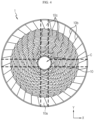
- FIG. 1 is a diagram for explaining a jelly-roll according to an embodiment of the present disclosure
- FIG. 2 is a diagram for explaining a state in which a first electrode applied to the jelly-roll of FIG. 1 is spread.
- the electrode assembly is an electrode assembly having a j elly-roll shape in which a stack including a first electrode, a second electrode and a separator is wound.
- the electrode assembly having a jelly-roll shape will be referred to as a jelly-roll 1.
- the first electrode includes a first electrode tab with a first polarity
- the second electrode includes a second electrode tab with a second polarity
- the first electrode may be a positive electrode or a negative electrode
- the second electrode may be an electrode having a polarity opposite to that of the first electrode.
- the separator is interposed between the first electrode and the second electrode.
- the stack in which the first electrode, the separator, the second electrode, and the separator are sequentially stacked at least once is wound based on a winding center C extending along a width direction of the first electrode and the second electrode, that is, a height direction of the jelly-roll 1 (parallel to the Z-axis) to form the jelly-roll 1. That is, the jelly-roll 1 has a structure in which a stack including a first electrode, a second electrode, and a separator interposed between the first and second electrodes is wound in one direction.
- Each of the first electrode and the second electrode includes an electrode tab and a coated portion.
- the first electrode includes a first electrode current collector and a first electrode active material coated on one surface or both surfaces of the first electrode current collector. At one end of the first electrode current collector in a width direction (parallel to the Z-axis), there is a non-coated portion on which the first electrode active material is not coated.
- the non-coated portion functions as a first electrode tab 10 by itself. That is, the first electrode tab 10 is the first non-coated portion.
- the first electrode tab 10 is provided above the electrode assembly accommodated in a battery can in a height direction (parallel to the Z-axis). At an opposite side of the non-coated portion of the first electrode current collector, there is a coated portion 20 coated with the first electrode active material.
- the second electrode includes a second electrode current collector and a second electrode active material coated on one surface or both surfaces of the second electrode current collector.
- a non-coated portion on which the second electrode active material is not coated.
- the non-coated portion functions as a second electrode tab by itself. That is, the second electrode tab 10 is the second non-coated portion.
- the second electrode tab is provided under the electrode assembly accommodated in the battery can in the height direction.
- At an opposite side of the non-coated portion of the second electrode current collector there is a coated portion coated with the second electrode active material.
- the positive active material coated on the positive electrode plate and the negative electrode active material coated on the negative electrode plate may be used without limitation as long as the active material is known in the art.
- the positive electrode active material may include alkali metal compounds represented by a general formula A[A x M y ]O 2+z (A includes at least one element among Li, Na and K; M includes at least one element selected from Ni, Co, Mn, Ca, Mg, Al, Ti, Si, Fe, Mo, V, Zr, Zn, Cu, Al, Mo, Sc, Zr, Ru, and Cr; x ⁇ 0, 1 ⁇ x + y ⁇ 2, 0.1 ⁇ z ⁇ 2; the stoichiometric modulus of components included in x, y, z and M is selected to remain electrically neutral).
- A includes at least one element among Li, Na and K
- M includes at least one element selected from Ni, Co, Mn, Ca, Mg, Al, Ti, Si, Fe, Mo, V, Zr, Zn, Cu, Al, Mo, Sc, Zr, Ru, and Cr
- the positive electrode active material may be an alkali metal compound xLiM 1 O 2 -(1-x)Li 2 M 2 O 3 (M 1 comprises at least one element having an average oxidation state 3; M 2 comprises at least one element having an average oxidation state 4; 0 ⁇ x ⁇ 1) disclosed in US6,677,082 , US6,680,143 , et al.
- the positive electrode active material may be lithium metal phosphate represented by a general formula Li a M 1 x Fe 1-x M 2 y P 1-y M 3 z O 4-z
- M 1 includes at least one element selected from Ti, Si, Mn, Co, Fe, V, Cr, Mo, Ni, Nd, Al, Mg and Al
- M 2 includes at least one element selected from Ti, Si, Mn, Co, Fe, V, Cr, Mo, Ni, Nd, Al, Mg, Al, As, Sb, Si, Ge, V and S
- M 3 includes a halogen element optionally including F; 0 ⁇ a ⁇ 2, 0 ⁇ x ⁇ 1, 0 ⁇ y ⁇ 1, 0 ⁇ z ⁇ 1; the stoichiometric modulus of components included in a, x, y, z, M 1 , M 2 , and M 3 are selected to remain electrically neutral), or Li 3 M 2 (PO 4 ) 3 [M includes at least one element selected from Ti, Si
- the positive electrode active material may include primary particles and/or secondary particles in which the primary particles are aggregated.
- the negative electrode active material may use a carbon material, lithium metal or lithium metal compound, silicon or silicon compound, tin or tin compound.
- Metal oxides such as TiO 2 and SnO 2 with a potential of less than 2 V may also be used as the negative electrode active material.
- the carbon material all of low-crystalline carbon, high-crystalline carbon, and the like may be used.
- the separator may use a porous polymer film, for example, a porous polymer film made of a polyolefin-based polymer such as ethylene homopolymer, propylene homopolymer, ethylene/butene copolymer, ethylene/hexene copolymer and ethylene/methacrylate copolymer, or laminates thereof.
- a porous polymer film for example, a porous polymer film made of a polyolefin-based polymer such as ethylene homopolymer, propylene homopolymer, ethylene/butene copolymer, ethylene/hexene copolymer and ethylene/methacrylate copolymer, or laminates thereof.
- the separator may use a conventional porous nonwoven fabric, for example, a nonwoven fabric made of high melting point glass fiber, polyethylene terephthalate fiber, or the like.
- At least one surface of the separator may include a coating layer of inorganic particles. It is also possible that the separator itself is made of a coating layer of inorganic particles. Particles constituting the coating layer may have a structure coupled with a binder so that interstitial volumes exist between adjacent particles.
- the inorganic particles may be formed of an inorganic material having a dielectric constant of 5 or more.
- the inorganic particles may include at least one material selected from the group consisting of Pb(Zr,Ti)O 3 (PZT), Pb 1-x La x Zr 1-y Ti y O 3 (PLZT), PB(Mg 3 Nb 2/3 )O 3 -PbTiO 3 (PMN-PT), BaTiO 3 , hafnia (HfO 2 ), SrTiO 3 , TiO 2 , Al 2 O 3 , ZrO 2 , SnO 2 , CeO 2 , MgO, CaO, ZnO and Y 2 O 3 .
- the electrolyte may be a salt having a structure such as A + B -- .
- a + includes an alkali metal cation such as Li + , Na + , or K + , or an ion composed of a combination thereof.
- B -- includes at least one anion selected from the group consisting of F -- , Cl -- , Br -- , I -- , NO 3 -- , N(CN) 2 -- , BF 4 -- , ClO 4 -- , AlO 4 -- , AlCl 4 -- , PF 6 -- , SbF 6 -- , AsF 6 -- , BF 2 C 2 O 4 -- , BC 4 O 8 -- , (CF 3 ) 2 PF 4 -- , (CF 3 ) 3 PF 3 - , (CF 3 ) 4 PF 2 -- , (CF 3 ) 5 PF -- , (CF 3 ) 6 P -- , CF 3 SO 3 -- , C 4 F 9 SO 3 -- , CF 3 CF 2 SO 3 --
- the electrolyte may also be dissolved in an organic solvent and then used.
- the organic solvent may use propylene carbonate (PC), ethylene carbonate (EC), diethyl carbonate (DEC), dimethyl carbonate (DMC), dipropyl carbonate (DPC), dimethyl sulfoxide, acetonitrile, dimethoxyethane, diethoxyethane, tetrahydrofuran, N-methyl-2-pyrrolidone (NMP), ethyl methyl carbonate (EMC), ⁇ -butyrolactone, or a mixture thereof.
- PC propylene carbonate
- EC ethylene carbonate
- DEC diethyl carbonate
- DMC dimethyl carbonate
- DPC dipropyl carbonate
- dimethyl sulfoxide acetonitrile, dimethoxyethane, diethoxyethane, tetrahydrofuran, N-methyl-2-pyrrolidone (NMP), ethyl methyl
- the first electrode and the second electrode extend in opposite directions along the height direction (parallel to the Z-axis) of the jelly-roll 1.
- the structure of the first electrode will be described in detail. However, this is only an exemplary description, and the structure of the first electrode to be described below may be applied to both the first electrode and the second electrode, or may be applied only to the second electrode.
- the first electrode tab 10 includes a plurality of slits 10a.
- the first electrode tab 10 may further include a plurality of cutting lines 10b and a bent portion 10c partitioned by the cutting lines 10b.
- the plurality of slits 10a may be formed by, for example, mold punching or laser notching.
- the plurality of slits 10a are formed along a circumferential direction of the jelly-roll 1, that is, a winding direction of the jelly-roll 1. At this time, the plurality of slits 10a may be formed on the same line. For example, the plurality of slits 10a may be formed on a straight line parallel to the winding direction of the first electrode and/or the second electrode. That is, the longitudinal extension lines of the slits 10a adjacent to each other along the winding direction may overlap each other.
- the distance between the plurality of slits 10a may gradually increase from a core of the jelly-roll 1 to an outer circumference thereof. That is, the plurality of slits 10a may be provided in a gradient pattern.
- the sheet-shaped first electrode and/or second electrode has a structure of being wound in one direction.
- the plurality of slits 10a are provided along the winding direction.
- the distance between the slits 10a may be configured to be relatively close, and the distance between the slits 10a may be configured to gradually increase toward the outer circumference. This is because, as the first electrode and/or the second electrode is wound in one direction, the radius of the jelly-roll 1 increases, and the length of the circumference formed by the layers constituting the jelly-roll 1 increases toward the outer circumference.
- the distance between the slits 10a should be increased as being closer to the outer circumference, so that a slit 10a provided in a previous layer and a slit 10a provided in a next layer may face each other to form an impregnation path IP.
- the distance between the slits 10a should increase as the number of windings increases.
- the distance between the slits 10a should increase as the number of windings increases.
- the exact position of the slit 10a for forming the impregnation path IP may vary depending on the number of slits 10a per circumference, the thickness of the first electrode, the thickness of the second electrode, the thickness of the separator, and the like.
- the slits 10a may be provided at points of a specific angle of the jelly-roll 1, the impregnation path IP may be formed effectively. Therefore, the electrolyte impregnation property at the electrode center of the jelly-roll 1 may be improved.
- the impregnation path IP may be reliably formed. Accordingly, it is possible to minimize the weakening of the strength of the first electrode tab 10 and/or the second electrode tab.
- the strength of the first electrode tab 10 may be secured at a certain level.
- the length of the plurality of slits 10a in the winding direction must be long. This is because the slit 10a provided in the previous layer and the slit 10a provided in the next layer are more likely to face each other when the length of the plurality of slits 10a in the winding direction is long.
- Such a structure is obtained since the increase in the circumferential length according to the increase in the number of windings is not put into consideration in the design.
- the strength of the first electrode tab 10 at the position where the plurality of slits 10a are formed may become very weak. That is, in the first electrode tab 10, the area of the cross section at the position where the slit 10a is formed, that is, the area of the cross section cut along a direction substantially perpendicular to the winding axis of the jelly-roll 1 (parallel to the X-Y plane) is reduced. Accordingly, the first electrode tab 10 may be damaged due to shock or vibration applied during the use of the cylindrical battery cell, which may cause poor performance of the cylindrical battery cell and/or safety issues such as ignition due to internal short circuit.
- the impregnation path IP since the slit 10a provided in the previous layer and the slit 10a provided in the next layer face each other, even if the length of the slit 10a in the winding direction is relatively small, the impregnation path IP may be reliably formed. According to this structure, the reduction of the area of the cross section of the first electrode tab 10 at the position where the slit 10a is formed, that is, the cross section cut along the direction perpendicular to the winding axis of jelly-roll 1 (parallel to the XY plane) may be minimized. Accordingly, the tensile strength of the first electrode tab 10 in a winding axis direction (parallel to the Z axis) may be improved. Therefore, in this case, even when an external force is applied to the first electrode tab 10, the first electrode tab 10 is not easily broken.
- FIG. 3 is a plan view of the jelly-roll of FIG. 1 .
- FIG. 4 is a diagram for explaining an impregnation path of the jelly-roll of FIG. 3
- FIG. 5 is a diagram for explaining an impregnation path of a jelly-roll according to another embodiment of the present disclosure.
- the slits 10a may be formed to have a constant length in the winding direction regardless of locations where the slits 10a are provided.
- the impregnation paths IP may be formed to have uniform widths.
- the lengths of the slits 10a in the winding direction may gradually increase from the core of the jelly-roll 1 toward the outer circumference. Accordingly, as can be seen in FIG. 5 , the widths of the impregnation paths IP may gradually increase toward the outer circumference of the jelly-roll 1. In this case, the center of the winding direction length of the slit 10a provided in the previous layer may coincide with the center of the winding direction length of the slit 10a provided in the next layer.
- the electrolyte since the area of the slit 10a provided in the outermost layer, which is a site where the electrolyte starts to be impregnated with the jelly-roll 1, is large, the electrolyte may be smoothly impregnated into the inside of the jelly-roll 1.
- the area of the slit 10a provided at the core is formed small, it is possible to minimize the reduction of the area of the cross section cut along a direction perpendicular to the winding axis of the jelly-roll 1 (parallel to the X-Y plane). Accordingly, the tensile strength of the first electrode tab 10 in the winding axis direction (parallel to the Z axis) may be improved. Therefore, in this case, even when an external force is applied to the first electrode tab 10, the first electrode tab 10 is not easily broken.
- the slit 10a may be arranged to be spaced apart from the cutting line 10b, which will be described later, by a predetermined distance along an extension direction (parallel to the Z-axis) of the winding axis. Accordingly, the possibility of breakage of the first electrode tab 10 due to an external force such as shock or vibration that may be applied during manufacturing and use of the cylindrical battery cell may be further reduced.
- the slit 10a may be provided only at the second electrode, or may be provided at both the first electrode and the second electrode.
- FIG. 3 is a front view of the jelly-roll of FIG. 1
- FIG. 6 is a front sectioned view of the jelly-roll of FIG. 1 .
- the first electrode tabs 10 may include a plurality of bent portions 10c formed to be spaced apart from each other along the winding direction of the jelly-roll 1 and partitioned by the plurality of cutting lines 10b formed to a predetermined depth from an end of the first electrode tab 10. Accordingly, the bent portion 10c is provided at one end of the first electrode tab 10. That is, the first electrode tab 10 may include a plurality of segments divided along the circumferential direction of the jelly-roll 1 by, for example, notching, and the plurality of segments may be bent along the radial direction of the jelly-roll 1. Each of the plurality of segments bented corresponds to the above-described bent portion 10c.
- the plurality of bent portions 10c may be bent, for example in a direction toward the winding axis of the jelly-roll 1 to cover at least a part of one surface of the jelly-roll 1 substantially perpendicular to the winding axis.
- the plurality of bent portions 10c may entirely cover one surface of the jelly-roll 1 perpendicular to the winding axis.
- the bent portion 10c provided at one end of the first electrode tab 10 is bent to cover one surface of the jelly-roll 1 perpendicular to the winding axis, a contact area between a current collecting plate (not shown) to be coupled on one surface of the jelly-roll 1 and the first electrode tab 10 may be secured widely. Accordingly, the internal resistance of the cylindrical battery cell may be reduced. In addition, the coupling strength between the jelly-roll 1 and the current collecting plate may be improved.
- electrolyte may be injected through a top opening of the battery can.
- the electrolyte since the plurality of bent portions 10c entirely cover one surface of the jelly-roll 1 perpendicular to the winding axis, the electrolyte may not be smoothly impregnated through the top of the jelly-roll 1.
- the electrolyte may not be impregnated to the center of the jelly-roll 1.
- the slits 10a adjacent to each other along the radial direction of the jelly-roll 1 may at least partially overlap each other to form an impregnation path IP through which the electrolyte can pass along the radial direction.
- the impregnation path IP may be formed from the outer circumferential surface of the jelly-roll 1 to a predetermined depth along the radial direction.
- the plurality of bent portions 10c provided at one end of the first electrode tab 10 may be bent in a direction toward the winding axis to entirely cover one surface of the jelly-roll 1 perpendicular to the winding axis.
- the slits 10a adjacent to each other along the radial direction of the jelly-roll 1 may at least partially overlap each other, thereby forming an impregnation path IP through which the electrolyte can pass along the radial direction.
- the impregnation path IP is formed along the radial direction from the outer circumferential surface of the jelly-roll 1 to the winding center C.
- the electrolyte may move to the center of the jelly-roll 1 through the impregnation paths IP formed through the jelly-roll 1.
- the electrolyte introduced into the impregnation paths IP may flow down due to the force of gravity. Therefore, in the jelly-roll 1 of the present disclosure, the entire area in the height direction (direction parallel to the Z axis) and the entire area in the radial direction may be uniformly impregnated by the electrolyte.
- the slit 10a when the bent portion 10c as described above is provided in the first electrode tab 10, the slit 10a may be provided in an area other than the area in which the bent portion 10c is formed. Accordingly, the slit 10a may be provided on the outer peripheral surface of the j elly-roll 1.
- FIG. 7 is a plan view of a jelly-roll having a different shape from the jelly-roll shown in FIG. 3
- FIG. 8 is a front sectioned view of the jelly-roll of FIG. 7 .
- the plurality of bent portions 10c may also be bent in a direction toward the winding axis of the jelly-roll 1 to cover only a part of one surface of the jelly-roll 1 perpendicular to the winding axis.
- the length of the first electrode tab 10 in an area adjacent to the winding center C of the jelly-roll 1 and the length of the first electrode tab 10 in an area adjacent to the outer circumferential surface of the jelly-roll 1 may be different from each other. Specifically, the length of the first electrode tab 10 in the area adjacent to the winding center C of the jelly-roll 1 may be shorter than the length of the first electrode tab 10 in the area adjacent to the outer circumferential surface of the jelly-roll 1. In this case, the cutting line 10b and the bent portion 10c may not be provided to the first electrode tab 10 in the area adjacent to the winding center C of the jelly-roll 1. That is, the plurality of cutting lines 10b and the plurality of bent portions 10c may be provided only to the first electrode tab 10 in the area adjacent to the outer circumferential surface of the j elly-roll 1.
- the first electrode tab 10 in the area adjacent to the winding center C of the jelly-roll 1, the first electrode tab 10 may have a structure that is open upward without being bent.
- the area whose upper side is not covered by the bent portion 10c will be referred to as a first area A1.
- the radial length of the first area A1 will be referred to as D1.
- the plurality of bent portions 10c provided to the first electrode tab 10 in the area adjacent to the outer circumferential surface of the jelly-roll 1 are bent in a direction toward the winding axis to cover only a part of one surface of the jelly-roll 1 perpendicular to the winding axis.
- the area whose upper side is covered by the bent portion 10c will be referred to as a second area A2.
- the radial length of the second area A2 will be referred to as D2.
- the electrolyte introduced through the top opening of the battery can smoothly flow into the first area A1. Therefore, the electrolyte impregnation property may be further improved.
- the impregnation rate of the second area A2 whose upper side is covered due to bending of the plurality of bent portions 10c provided to the first electrode tab 10 toward the core may be slightly lower than the impregnation rate of the first area A1 whose upper side is not covered. Therefore, it is necessary to improve the impregnation rate of the second area A2.
- the depth P of the impregnation path IP may be greater than or equal to the radial length of the area covered by the bent portion 10c, in one surface of the jelly-roll 1 perpendicular to the winding axis. That is, referring to FIG. 8 , the depth P of the impregnation path IP may be formed to be greater than or equal to the radial length D2 of the second area A2.
- the electrolyte may move to at least a boundary point between the second area A2 and the first area A1 through the impregnation path IP.
- the electrolyte may move beyond the second area A2 to the first area A1. After that, the electrolyte may flow down due to the force of gravity. Therefore, the jelly-roll 1 of the present disclosure may be uniformly impregnated by the electrolyte even to the inside thereof.
- the cutting line 10b and the bent portion 10c are provided to the first electrode.
- the cutting line 10b and the bent portion 10c may also be provided only to the second electrode or to both the first electrode and the second electrode.
- the electrolyte impregnation property of the jelly-roll of the present disclosure was evaluated.
- a drop test and a vibration test were performed to evaluate the strength of the electrode tab.
- a jelly-roll in which slits are formed for electrolyte impregnation is fabricated. Then, after the jelly-roll is received through the top or bottom opening of the battery can, electrolyte is injected into the battery can. After the electrolyte is injected, it is aged for 24 hours, and then the level of impregnation of the electrolyte (checking whether a non-impregnation region exists) is analyzed.
- the cylindrical battery cell After the jelly-roll and the current collecting plate are welded, this is inserted into the battery can to manufacture a cylindrical battery cell. After that, the cylindrical battery cell fully discharged to 2.5 V is vibrated. The vibration method is to change vibration the frequency every 15 minutes as 7 Hz ⁇ 200 Hz, which is repeated 12 times in each of X-axis, Y-axis and Z-axis directions. After the vibration test is completed, it is checked whether short circuit and/or ignition occurs in the cylindrical battery cell.
- a jelly-roll was manufactured such that a plurality of slits are formed on the same line and the distance between the plurality of slits gradually increases from the core of the jelly-roll toward the outer circumference (gradient pattern type).
- Example 1 Except that a plurality of slits were provided at regular intervals, a jelly-roll was manufactured with the other conditions being the same as in Example 1.
- a jelly-roll was manufactured such that among the plurality of slits, slits adjacent to each other along the winding direction were not formed on the same line but were provided at staggered positions (zigzag type).
- Example 1 there was no non-impregnation area in the jelly-roll since the electrolyte impregnation property was excellent.
- the jelly-roll of Example 1 passed the drop test and the vibration test, so it might be confirmed that the electrode tab had excellent strength.
- the electrolyte impregnation property was satisfactory, but since a plurality of slits elongated in the winding direction were provided on the same line at regular intervals, the strength of the electrode tab was not secured.
- the jelly-roll of the comparative example 2 was damaged in a part of the electrode tab as a result of the drop test and the vibration test. That is, the jelly-roll of the comparative example 2 could not secure the quality and safety of the battery since the strength of the electrode tab was low.
- the electrolyte impregnation property was satisfied, but the strength of the electrode tab was not secured because a plurality of slits elongated in the winding direction were provided in a zigzag pattern at alternating positions.
- the jelly-roll of the comparative example 3 was damaged in a part of the electrode tab as a result of the drop test and the vibration test. That is, the jelly-roll of the comparative example 3 could not secure the quality and safety of the battery since the strength of the electrode tab was low.
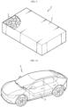
- FIG. 9 is a diagram for explaining a battery pack including at least one cylindrical battery cell that has the jelly-roll of FIG. 1 .
- a battery pack 3 includes an assembly in which cylindrical battery cells are electrically connected and a pack housing 2 for accommodating the assembly.
- the cylindrical battery cell is a battery cell according to the above embodiment.
- parts such as a bus bar, a cooling unit, and an external terminal for electrical connection of cylindrical battery cells are omitted for convenience of illustration.
- the battery pack 3 may be mounted on the vehicle.
- the vehicle may be, for example, an electric vehicle, a hybrid electric vehicle, or a plug-in hybrid vehicle.
- the vehicle includes a four-wheeled vehicle or a two-wheeled vehicle.
- FIG. 10 is a diagram for explaining a vehicle that includes the battery pack of FIG. 9 .
- a vehicle 5 includes the battery pack 3 according to an embodiment of the present disclosure.
- the vehicle 5 operates by receiving power from the battery pack 3 according to an embodiment of the present disclosure.
Landscapes
- Chemical & Material Sciences (AREA)
- Chemical Kinetics & Catalysis (AREA)
- Electrochemistry (AREA)
- General Chemical & Material Sciences (AREA)
- Engineering & Computer Science (AREA)
- Manufacturing & Machinery (AREA)
- Life Sciences & Earth Sciences (AREA)
- Sustainable Development (AREA)
- Sustainable Energy (AREA)
- Power Engineering (AREA)
- Transportation (AREA)
- Mechanical Engineering (AREA)
- Secondary Cells (AREA)
- Connection Of Batteries Or Terminals (AREA)
Applications Claiming Priority (2)
| Application Number | Priority Date | Filing Date | Title |
|---|---|---|---|
| KR20210153452 | 2021-11-09 | ||
| PCT/KR2022/016735 WO2023085665A1 (fr) | 2021-11-09 | 2022-10-28 | Rouleau de gelée doté d'une propriété d'imprégnation d'électrolyte améliorée, et élément de batterie cylindrique, bloc-batterie et véhicule le comprenant |
Publications (2)
| Publication Number | Publication Date |
|---|---|
| EP4376140A1 true EP4376140A1 (fr) | 2024-05-29 |
| EP4376140A4 EP4376140A4 (fr) | 2025-07-16 |
Family
ID=86336396
Family Applications (1)
| Application Number | Title | Priority Date | Filing Date |
|---|---|---|---|
| EP22893087.1A Pending EP4376140A4 (fr) | 2021-11-09 | 2022-10-28 | Rouleau de gelée doté d'une propriété d'imprégnation d'électrolyte améliorée, et élément de batterie cylindrique, bloc-batterie et véhicule le comprenant |
Country Status (6)
| Country | Link |
|---|---|
| US (1) | US20250015455A1 (fr) |
| EP (1) | EP4376140A4 (fr) |
| JP (1) | JP7767589B2 (fr) |
| KR (1) | KR20230067518A (fr) |
| CA (1) | CA3237014A1 (fr) |
| WO (1) | WO2023085665A1 (fr) |
Cited By (1)
| Publication number | Priority date | Publication date | Assignee | Title |
|---|---|---|---|---|
| EP4539244A4 (fr) * | 2022-07-19 | 2025-10-15 | Lg Energy Solution Ltd | Ensemble électrode, batterie et bloc-batterie et véhicule le comprenant |
Families Citing this family (1)
| Publication number | Priority date | Publication date | Assignee | Title |
|---|---|---|---|---|
| EP4618200A1 (fr) * | 2024-03-12 | 2025-09-17 | SK On Co., Ltd. | Électrode pour batterie secondaire, ensemble électrode pour batterie secondaire la comprenant et batterie secondaire la comprenant |
Family Cites Families (12)
| Publication number | Priority date | Publication date | Assignee | Title |
|---|---|---|---|---|
| JP2001093511A (ja) * | 1999-09-22 | 2001-04-06 | Honda Motor Co Ltd | 巻型円筒電池 |
| US6677082B2 (en) | 2000-06-22 | 2004-01-13 | The University Of Chicago | Lithium metal oxide electrodes for lithium cells and batteries |
| US6680143B2 (en) | 2000-06-22 | 2004-01-20 | The University Of Chicago | Lithium metal oxide electrodes for lithium cells and batteries |
| JP4401634B2 (ja) * | 2002-09-04 | 2010-01-20 | パナソニック株式会社 | 蓄電池およびその製造方法 |
| KR100599749B1 (ko) * | 2004-06-23 | 2006-07-12 | 삼성에스디아이 주식회사 | 이차 전지와 이에 사용되는 전극 조립체 |
| JP4655657B2 (ja) * | 2005-02-08 | 2011-03-23 | 新神戸電機株式会社 | 捲回形鉛蓄電池 |
| JP2008243672A (ja) * | 2007-03-28 | 2008-10-09 | Toshiba Corp | 二次電池用捲回電極、リチウムイオン二次電池および二次電池パック |
| KR100964490B1 (ko) * | 2007-10-12 | 2010-06-21 | 킴스테크날리지 주식회사 | 쿼지바이폴라 구조를 갖는 전기화학셀 |
| JP5187729B2 (ja) * | 2007-11-09 | 2013-04-24 | Necエナジーデバイス株式会社 | 密閉型電池 |
| JP5957239B2 (ja) * | 2012-02-21 | 2016-07-27 | 日立オートモティブシステムズ株式会社 | 二次電池 |
| KR102262668B1 (ko) * | 2014-01-28 | 2021-06-09 | 리튬 웍스 테크놀로지 비.브이. | 원주형 전기화학 셀 및 제조 방법 |
| PL4095965T3 (pl) * | 2021-02-09 | 2025-09-01 | Contemporary Amperex Technology (Hong Kong) Limited | Zespół elektrod, ogniwo baterii, bateria, urządzenie elektryczne |
-
2022
- 2022-10-28 EP EP22893087.1A patent/EP4376140A4/fr active Pending
- 2022-10-28 US US18/706,683 patent/US20250015455A1/en active Pending
- 2022-10-28 CA CA3237014A patent/CA3237014A1/fr active Pending
- 2022-10-28 KR KR1020220141255A patent/KR20230067518A/ko active Pending
- 2022-10-28 WO PCT/KR2022/016735 patent/WO2023085665A1/fr not_active Ceased
- 2022-10-28 JP JP2024517144A patent/JP7767589B2/ja active Active
Cited By (1)
| Publication number | Priority date | Publication date | Assignee | Title |
|---|---|---|---|---|
| EP4539244A4 (fr) * | 2022-07-19 | 2025-10-15 | Lg Energy Solution Ltd | Ensemble électrode, batterie et bloc-batterie et véhicule le comprenant |
Also Published As
| Publication number | Publication date |
|---|---|
| KR20230067518A (ko) | 2023-05-16 |
| JP7767589B2 (ja) | 2025-11-11 |
| EP4376140A4 (fr) | 2025-07-16 |
| JP2024533607A (ja) | 2024-09-12 |
| CA3237014A1 (fr) | 2023-05-19 |
| WO2023085665A1 (fr) | 2023-05-19 |
| US20250015455A1 (en) | 2025-01-09 |
Similar Documents
| Publication | Publication Date | Title |
|---|---|---|
| EP4293810A1 (fr) | Ensemble d'électrodes ayant une excellente imprégnabilité d'électrolyte, et batterie, bloc-batterie, et véhicule comprenant celui-ci | |
| EP4199206B1 (fr) | Structure de rivetage de borne d'électrode, et batterie secondaire, bloc-batterie et automobile la comprenant | |
| US20240396168A1 (en) | Separator, electrode assembly, cylindrical battery cell, and battery pack and vehicle comprising the same | |
| US12537231B2 (en) | Electrode assembly, cylindrical battery cell, and battery pack and vehicle including the same | |
| US20240128605A1 (en) | Electrode assembly, battery, and battery pack and vehicle including the same | |
| US12451524B2 (en) | Electrode assembly, secondary battery, battery pack and vehicle including the same | |
| KR20220139818A (ko) | 전극 조립체, 배터리 셀, 배터리 팩 및 자동차 | |
| EP4290630B1 (fr) | Ensemble d'électrodes, batterie, et bloc-batterie et véhicule comprenant les mêmes | |
| US20240266583A1 (en) | Electrode assembly, battery, and battery pack and vehicle including the same | |
| US20240014521A1 (en) | Secondary battery, and battery pack and vehicle comprising same | |
| EP4376140A1 (fr) | Rouleau de gelée doté d'une propriété d'imprégnation d'électrolyte améliorée, et élément de batterie cylindrique, bloc-batterie et véhicule le comprenant | |
| EP4297173A1 (fr) | Batterie secondaire, et bloc-batterie et véhicule comprenant celle-ci | |
| CN219086023U (zh) | 卷芯、圆柱形电池单元、电池组和车辆 | |
| EP4358229A1 (fr) | Ensemble électrode, batterie secondaire, bloc-batterie et véhicule | |
| US20260051529A1 (en) | Electrode assembly, cylindrical battery cell, and battery pack and vehicle including the same | |
| JP7827366B2 (ja) | 安全性が改善された角型二次電池 | |
| EP4329043A1 (fr) | Batterie rechargeable prismatique à stabilité améliorée | |
| KR20220128242A (ko) | 전해액 함침성이 우수한 젤리-롤 및 이를 포함하는 원통형 배터리 셀, 배터리 팩 및 자동차 | |
| KR20240002220A (ko) | 전극 조립체, 이차 전지, 배터리 팩 및 자동차 |
Legal Events
| Date | Code | Title | Description |
|---|---|---|---|
| STAA | Information on the status of an ep patent application or granted ep patent |
Free format text: STATUS: THE INTERNATIONAL PUBLICATION HAS BEEN MADE |
|
| PUAI | Public reference made under article 153(3) epc to a published international application that has entered the european phase |
Free format text: ORIGINAL CODE: 0009012 |
|
| STAA | Information on the status of an ep patent application or granted ep patent |
Free format text: STATUS: REQUEST FOR EXAMINATION WAS MADE |
|
| 17P | Request for examination filed |
Effective date: 20240221 |
|
| AK | Designated contracting states |
Kind code of ref document: A1 Designated state(s): AL AT BE BG CH CY CZ DE DK EE ES FI FR GB GR HR HU IE IS IT LI LT LU LV MC ME MK MT NL NO PL PT RO RS SE SI SK SM TR |
|
| DAV | Request for validation of the european patent (deleted) | ||
| DAX | Request for extension of the european patent (deleted) | ||
| A4 | Supplementary search report drawn up and despatched |
Effective date: 20250618 |
|
| RIC1 | Information provided on ipc code assigned before grant |
Ipc: H01M 10/04 20060101AFI20250612BHEP Ipc: H01M 50/533 20210101ALI20250612BHEP Ipc: H01M 10/0587 20100101ALI20250612BHEP Ipc: H01M 50/538 20210101ALI20250612BHEP |