EP4376141A1 - Module de batterie et bloc-batterie le comprenant - Google Patents
Module de batterie et bloc-batterie le comprenant Download PDFInfo
- Publication number
- EP4376141A1 EP4376141A1 EP22922354.0A EP22922354A EP4376141A1 EP 4376141 A1 EP4376141 A1 EP 4376141A1 EP 22922354 A EP22922354 A EP 22922354A EP 4376141 A1 EP4376141 A1 EP 4376141A1
- Authority
- EP
- European Patent Office
- Prior art keywords
- battery
- battery cell
- side portion
- battery module
- module according
- Prior art date
- Legal status (The legal status is an assumption and is not a legal conclusion. Google has not performed a legal analysis and makes no representation as to the accuracy of the status listed.)
- Pending
Links
Images





Classifications
-
- H—ELECTRICITY
- H01—ELECTRIC ELEMENTS
- H01M—PROCESSES OR MEANS, e.g. BATTERIES, FOR THE DIRECT CONVERSION OF CHEMICAL ENERGY INTO ELECTRICAL ENERGY
- H01M10/00—Secondary cells; Manufacture thereof
- H01M10/04—Construction or manufacture in general
- H01M10/049—Processes for forming or storing electrodes in the battery container
-
- H—ELECTRICITY
- H01—ELECTRIC ELEMENTS
- H01M—PROCESSES OR MEANS, e.g. BATTERIES, FOR THE DIRECT CONVERSION OF CHEMICAL ENERGY INTO ELECTRICAL ENERGY
- H01M50/00—Constructional details or processes of manufacture of the non-active parts of electrochemical cells other than fuel cells, e.g. hybrid cells
- H01M50/20—Mountings; Secondary casings or frames; Racks, modules or packs; Suspension devices; Shock absorbers; Transport or carrying devices; Holders
- H01M50/204—Racks, modules or packs for multiple batteries or multiple cells
- H01M50/207—Racks, modules or packs for multiple batteries or multiple cells characterised by their shape
- H01M50/211—Racks, modules or packs for multiple batteries or multiple cells characterised by their shape adapted for pouch cells
-
- H—ELECTRICITY
- H01—ELECTRIC ELEMENTS
- H01M—PROCESSES OR MEANS, e.g. BATTERIES, FOR THE DIRECT CONVERSION OF CHEMICAL ENERGY INTO ELECTRICAL ENERGY
- H01M10/00—Secondary cells; Manufacture thereof
- H01M10/04—Construction or manufacture in general
- H01M10/0413—Large-sized flat cells or batteries for motive or stationary systems with plate-like electrodes
-
- H—ELECTRICITY
- H01—ELECTRIC ELEMENTS
- H01M—PROCESSES OR MEANS, e.g. BATTERIES, FOR THE DIRECT CONVERSION OF CHEMICAL ENERGY INTO ELECTRICAL ENERGY
- H01M10/00—Secondary cells; Manufacture thereof
- H01M10/04—Construction or manufacture in general
- H01M10/0436—Small-sized flat cells or batteries for portable equipment
-
- H—ELECTRICITY
- H01—ELECTRIC ELEMENTS
- H01M—PROCESSES OR MEANS, e.g. BATTERIES, FOR THE DIRECT CONVERSION OF CHEMICAL ENERGY INTO ELECTRICAL ENERGY
- H01M10/00—Secondary cells; Manufacture thereof
- H01M10/60—Heating or cooling; Temperature control
- H01M10/61—Types of temperature control
- H01M10/613—Cooling or keeping cold
-
- H—ELECTRICITY
- H01—ELECTRIC ELEMENTS
- H01M—PROCESSES OR MEANS, e.g. BATTERIES, FOR THE DIRECT CONVERSION OF CHEMICAL ENERGY INTO ELECTRICAL ENERGY
- H01M10/00—Secondary cells; Manufacture thereof
- H01M10/60—Heating or cooling; Temperature control
- H01M10/64—Heating or cooling; Temperature control characterised by the shape of the cells
- H01M10/647—Prismatic or flat cells, e.g. pouch cells
-
- H—ELECTRICITY
- H01—ELECTRIC ELEMENTS
- H01M—PROCESSES OR MEANS, e.g. BATTERIES, FOR THE DIRECT CONVERSION OF CHEMICAL ENERGY INTO ELECTRICAL ENERGY
- H01M10/00—Secondary cells; Manufacture thereof
- H01M10/60—Heating or cooling; Temperature control
- H01M10/65—Means for temperature control structurally associated with the cells
- H01M10/653—Means for temperature control structurally associated with the cells characterised by electrically insulating or thermally conductive materials
-
- H—ELECTRICITY
- H01—ELECTRIC ELEMENTS
- H01M—PROCESSES OR MEANS, e.g. BATTERIES, FOR THE DIRECT CONVERSION OF CHEMICAL ENERGY INTO ELECTRICAL ENERGY
- H01M10/00—Secondary cells; Manufacture thereof
- H01M10/60—Heating or cooling; Temperature control
- H01M10/65—Means for temperature control structurally associated with the cells
- H01M10/655—Solid structures for heat exchange or heat conduction
- H01M10/6553—Terminals or leads
-
- H—ELECTRICITY
- H01—ELECTRIC ELEMENTS
- H01M—PROCESSES OR MEANS, e.g. BATTERIES, FOR THE DIRECT CONVERSION OF CHEMICAL ENERGY INTO ELECTRICAL ENERGY
- H01M10/00—Secondary cells; Manufacture thereof
- H01M10/60—Heating or cooling; Temperature control
- H01M10/65—Means for temperature control structurally associated with the cells
- H01M10/655—Solid structures for heat exchange or heat conduction
- H01M10/6554—Rods or plates
-
- H—ELECTRICITY
- H01—ELECTRIC ELEMENTS
- H01M—PROCESSES OR MEANS, e.g. BATTERIES, FOR THE DIRECT CONVERSION OF CHEMICAL ENERGY INTO ELECTRICAL ENERGY
- H01M10/00—Secondary cells; Manufacture thereof
- H01M10/60—Heating or cooling; Temperature control
- H01M10/65—Means for temperature control structurally associated with the cells
- H01M10/655—Solid structures for heat exchange or heat conduction
- H01M10/6554—Rods or plates
- H01M10/6555—Rods or plates arranged between the cells
-
- H—ELECTRICITY
- H01—ELECTRIC ELEMENTS
- H01M—PROCESSES OR MEANS, e.g. BATTERIES, FOR THE DIRECT CONVERSION OF CHEMICAL ENERGY INTO ELECTRICAL ENERGY
- H01M50/00—Constructional details or processes of manufacture of the non-active parts of electrochemical cells other than fuel cells, e.g. hybrid cells
- H01M50/10—Primary casings; Jackets or wrappings
- H01M50/102—Primary casings; Jackets or wrappings characterised by their shape or physical structure
- H01M50/105—Pouches or flexible bags
-
- H—ELECTRICITY
- H01—ELECTRIC ELEMENTS
- H01M—PROCESSES OR MEANS, e.g. BATTERIES, FOR THE DIRECT CONVERSION OF CHEMICAL ENERGY INTO ELECTRICAL ENERGY
- H01M50/00—Constructional details or processes of manufacture of the non-active parts of electrochemical cells other than fuel cells, e.g. hybrid cells
- H01M50/10—Primary casings; Jackets or wrappings
- H01M50/183—Sealing members
-
- H—ELECTRICITY
- H01—ELECTRIC ELEMENTS
- H01M—PROCESSES OR MEANS, e.g. BATTERIES, FOR THE DIRECT CONVERSION OF CHEMICAL ENERGY INTO ELECTRICAL ENERGY
- H01M50/00—Constructional details or processes of manufacture of the non-active parts of electrochemical cells other than fuel cells, e.g. hybrid cells
- H01M50/10—Primary casings; Jackets or wrappings
- H01M50/183—Sealing members
- H01M50/184—Sealing members characterised by their shape or structure
-
- H—ELECTRICITY
- H01—ELECTRIC ELEMENTS
- H01M—PROCESSES OR MEANS, e.g. BATTERIES, FOR THE DIRECT CONVERSION OF CHEMICAL ENERGY INTO ELECTRICAL ENERGY
- H01M50/00—Constructional details or processes of manufacture of the non-active parts of electrochemical cells other than fuel cells, e.g. hybrid cells
- H01M50/10—Primary casings; Jackets or wrappings
- H01M50/183—Sealing members
- H01M50/186—Sealing members characterised by the disposition of the sealing members
-
- H—ELECTRICITY
- H01—ELECTRIC ELEMENTS
- H01M—PROCESSES OR MEANS, e.g. BATTERIES, FOR THE DIRECT CONVERSION OF CHEMICAL ENERGY INTO ELECTRICAL ENERGY
- H01M50/00—Constructional details or processes of manufacture of the non-active parts of electrochemical cells other than fuel cells, e.g. hybrid cells
- H01M50/20—Mountings; Secondary casings or frames; Racks, modules or packs; Suspension devices; Shock absorbers; Transport or carrying devices; Holders
- H01M50/204—Racks, modules or packs for multiple batteries or multiple cells
-
- H—ELECTRICITY
- H01—ELECTRIC ELEMENTS
- H01M—PROCESSES OR MEANS, e.g. BATTERIES, FOR THE DIRECT CONVERSION OF CHEMICAL ENERGY INTO ELECTRICAL ENERGY
- H01M50/00—Constructional details or processes of manufacture of the non-active parts of electrochemical cells other than fuel cells, e.g. hybrid cells
- H01M50/20—Mountings; Secondary casings or frames; Racks, modules or packs; Suspension devices; Shock absorbers; Transport or carrying devices; Holders
- H01M50/271—Lids or covers for the racks or secondary casings
-
- H—ELECTRICITY
- H01—ELECTRIC ELEMENTS
- H01M—PROCESSES OR MEANS, e.g. BATTERIES, FOR THE DIRECT CONVERSION OF CHEMICAL ENERGY INTO ELECTRICAL ENERGY
- H01M50/00—Constructional details or processes of manufacture of the non-active parts of electrochemical cells other than fuel cells, e.g. hybrid cells
- H01M50/50—Current conducting connections for cells or batteries
- H01M50/531—Electrode connections inside a battery casing
- H01M50/533—Electrode connections inside a battery casing characterised by the shape of the leads or tabs
-
- H—ELECTRICITY
- H01—ELECTRIC ELEMENTS
- H01M—PROCESSES OR MEANS, e.g. BATTERIES, FOR THE DIRECT CONVERSION OF CHEMICAL ENERGY INTO ELECTRICAL ENERGY
- H01M50/00—Constructional details or processes of manufacture of the non-active parts of electrochemical cells other than fuel cells, e.g. hybrid cells
- H01M50/50—Current conducting connections for cells or batteries
- H01M50/531—Electrode connections inside a battery casing
- H01M50/538—Connection of several leads or tabs of wound or folded electrode stacks
-
- H—ELECTRICITY
- H01—ELECTRIC ELEMENTS
- H01M—PROCESSES OR MEANS, e.g. BATTERIES, FOR THE DIRECT CONVERSION OF CHEMICAL ENERGY INTO ELECTRICAL ENERGY
- H01M50/00—Constructional details or processes of manufacture of the non-active parts of electrochemical cells other than fuel cells, e.g. hybrid cells
- H01M50/50—Current conducting connections for cells or batteries
- H01M50/543—Terminals
- H01M50/547—Terminals characterised by the disposition of the terminals on the cells
- H01M50/548—Terminals characterised by the disposition of the terminals on the cells on opposite sides of the cell
-
- Y—GENERAL TAGGING OF NEW TECHNOLOGICAL DEVELOPMENTS; GENERAL TAGGING OF CROSS-SECTIONAL TECHNOLOGIES SPANNING OVER SEVERAL SECTIONS OF THE IPC; TECHNICAL SUBJECTS COVERED BY FORMER USPC CROSS-REFERENCE ART COLLECTIONS [XRACs] AND DIGESTS
- Y02—TECHNOLOGIES OR APPLICATIONS FOR MITIGATION OR ADAPTATION AGAINST CLIMATE CHANGE
- Y02E—REDUCTION OF GREENHOUSE GAS [GHG] EMISSIONS, RELATED TO ENERGY GENERATION, TRANSMISSION OR DISTRIBUTION
- Y02E60/00—Enabling technologies; Technologies with a potential or indirect contribution to GHG emissions mitigation
- Y02E60/10—Energy storage using batteries
Definitions
- the present disclosure relates to a battery module and a battery pack including the same, and more particularly, to a battery module with improved cooling performance, and a battery pack including the same.
- a secondary battery has attracted considerable attention as an energy source for power-driven devices, such as an electric bicycle, an electric vehicle, and a hybrid electric vehicle, as well as an energy source for mobile devices, such as a mobile phone, a digital camera, a laptop computer and a wearable device.
- a medium- or large-sized battery module having a plurality of battery cells electrically connected to one another is used.
- a prismatic battery, a pouch-type battery, or the like which can be stacked with high integration and has a small weight relative to capacity, is mainly used as a battery cell of the medium- or large-sized battery modules.
- a battery module has a structure in which a plurality of cell assemblies including a plurality of unit battery cells are connected in series to obtain high output.
- the battery cell includes positive and negative electrode current collectors, a separator, an active material, an electrolyte, and the like, and thus can be repeatedly charged and discharged through an electrochemical reaction between components.
- a battery module composed of at least one battery cell first and then configure a battery pack by using at least one battery module and adding other components.
- a secondary battery when a secondary battery is heated over a proper temperature, the performance of the secondary battery may deteriorate, and in the worst case, there is also a risk of an explosion or ignition.
- a plurality of secondary batteries that is, a battery module or a battery pack having battery cells can accumulate the heat emitted from the plurality of battery cells in a narrow space, which may raise the temperature of the battery module quickly and severely.
- a battery module including a large number of battery cells, and a battery pack equipped with such a battery module can obtain high output, but it is not easy to remove heat generated from the battery cells during charging and discharging.
- the heat dissipation of the battery cell is not properly performed, deterioration of the battery cells is accelerated, the lifespan is shortened, and the possibility of explosion or ignition increases.
- the battery module may be frequently exposed to direct sunlight and may be placed under high-temperature conditions, for example, in summer or in a desert.
- FIG. 1 is a perspective view of a conventional battery module.
- FIG. 2 is a cross-sectional view taken along the cutting line A-A' in FIG. 1 .
- FIG. 3 is an enlarged view of a section B of FIG. 2 .
- a conventional battery module 10 includes a battery cell stack 12 in which a plurality of battery cells 11 are stacked in one direction, a module frame 25 that houses the battery cell stack 12, and end plates 15 that cover the front and rear surfaces of the battery cell stack 12.
- the module frame 25 includes a lower frame 30 that covers the lower part and both side surfaces of the battery cell stack 12, and an upper plate 40 that covers the upper surface of the battery cell stack 12. Additionally, a thermally conductive resin layer 31 located between the lower portion of the battery cell stack 12 and the bottom portion of the module frame 25 may be formed.
- the battery cell 11 of the conventional battery module 10 is configured by folding the sealing portion 11a or maintaining it as it is.
- the sealing portion 11a is disposed as shown in FIG. 3 , it is difficult to utilize the space between the upper plate 40 and the battery cell stack 12 due to the sealing portion 11a. Therefore, due to the arrangement of the sealing portion 11a, not only it is difficult to achieve an effective cooling effect through the upper portion of the battery module 10, but also there is a problem that the cooling performance is deteriorated by an air layer formed adjacent to the sealing portion 11a, such as the space between the sealing portion 11a and the main body of the battery cell 10.
- a battery module comprising: a battery cell stack including a plurality of battery cells; and a module frame that houses the battery cell stack, wherein the battery cell comprises an electrode assembly; and a battery case that is opened at its front and rear surfaces housing the electrode assembly, and wherein a sealing portion is formed on each of the front and the rear surface of the battery case.
- the battery case may be a tubular case that is opened at its front and rear surfaces.
- the battery module may further comprise a thermally conductive resin layer located between the upper portion of the battery cell stack and the module frame, wherein an upper portion of the battery cell stack that contacts the thermally conductive resin layer may have a flat shape.
- the battery cell may be sealed by the two sealing portions.
- the battery cells further comprise electrode leads formed protrusively from the battery cells, and the sealing portion may be formed to be adjacent to the electrode lead.
- the battery module according to another embodiment of the present disclosure further comprises a sealing portion formed at one side portion of the battery cell, wherein the sealing portion formed on the one side may be formed to protrude from the battery case.
- the sealing portion formed at the one side portion may be formed to protrude from the unopened one surface of the battery case.
- One side portion of the battery cell may be an upper one side portion of the battery case.
- the sealing portion formed at the one side portion may be formed at an edge of the one side portion.
- the protrusively formed sealing portion may be bent and adhered from the edge of the one side portion toward the center of the one side portion.
- the sealing portion formed at the one side portion may be formed at the center of the one side portion.
- the protrusively formed sealing portion may be bent and adhered from the center of the one side portion toward the edge of the one side portion.
- a battery pack comprising the above-mentioned battery module.
- a battery module includes a battery cell in which a sealing portion is minimized, thereby capable of effectively cooling a battery cell whose temperature rises in a high current and rapid charging environment.
- the internal temperature deviation of the battery module can be minimized, thereby improving the stability of the battery module.
- planar it means when a target portion is viewed from the upper side
- cross-sectional it means when a target portion is viewed from the side of a cross section cut vertically.
- FIG. 4 is an exploded perspective view of a battery module according to one embodiment of the present disclosure.
- the battery module 100 includes a battery cell stack 120 in which a plurality of battery cells 110 are stacked, and a module frame 200 that houses the battery cell stack 120.
- the module frame 200 includes a U-shaped frame 300 which is opened at its upper, front and rear surfaces and covers the lower portion and both side portions of the battery cell stack 120, and an upper plate 400 that covers the upper portion of the battery cell stack 120.
- the U-shaped frame 300 may include a bottom portion 300a supporting the lower portion of the battery cell stack 120, and side surface portions 300b each extending upward from both ends of the bottom portion 300a.
- the module frame 200 is not limited thereto, and can be replaced with a frame having another shape such as an L-shaped frame or a mono-frame surrounding the battery cell stack 120 except the front and rear surfaces.
- the battery cell stack 120 housed inside the module frame 200 can be physically protected through the module frame 200.
- the upper plate 400 can cover the opened upper side surface of the module frame 200.
- the end plate 150 can cover the front and rear surfaces of the battery cell stack 120 that are opened in the module frame 200.
- the end plate 150 can be weld-coupled with the front and rear end edges of the upper plate 400 and the front and rear end edges of the module frame 200.
- a busbar frame 130 can be formed between the end plate 150 and the front and rear surfaces of the battery cell stack 120.
- the busbar frame 130 can cover the portion of the battery cell stack 120 exposed from the module frame 200.
- the plurality of busbars 160 mounted to the busbar frame 130 are formed protrusively from the battery cells 110, and can be connected with the electrode leads 111 and 112 mounted on the busbar frame 130. At this time, a slot through which the electrode leads 111 and 112 pass may be formed in the busbar 160. Therefore, the electrode leads 111 and 112 and the busbar 160 passing through the slot of the busbar 160 may contact with each other.
- the battery module 100 further includes a first thermal conductive resin layer 310 located between the lower surface of the battery cell stack 120 and the bottom portion of the module frame 200, that is, the bottom portion 300a of the frame member 300, wherein the first thermal conductive resin layer 310 may play a role of transferring heat generated in the battery cell 110 to the bottom of the battery module 100 and fixing the battery cell stack 120.
- the battery module 100 may further include a second thermally conductive resin layer 320 formed between the upper portion of the battery cell stack 120 and the upper portion of the module frame 200, that is, the upper plate 400. Therefore, the heat generated in the battery cell 110 can be transferred even through the upper portion of the module frame 200 via the second thermally conductive resin layer 320.
- the battery module 100 includes a heat transfer path to the upper portion of the module frame 200 through the second thermally conductive resin layer 320, rather than a one-way path through the bottom portion of the module frame 200, thereby capable of improving the cooling performance.
- the first thermally conductive resin layer 310 and the second thermally conductive resin layer 320 may be formed by a method of applying and curing a thermal resin. Therefore, the first thermally conductive resin layer 310 and the second thermally conductive resin layer 320 are illustrated in a plate shape, but in the process of applying and then curing the thermally conductive resin, it can be freely deformed in accordance with the shape of other components.
- a conventional battery module was configured to release the heat generated in the battery cells through the thermal conductive resin layer formed at a lower portion of the battery cell.
- the heat generated in the battery cells cannot be efficiently cooled only by the thermally conductive resin layer formed under the battery cell stack and the cooling structure through the one-way path via the bottom portion of the module frame.
- the battery cell 10 of a conventional battery module had a problem that the sealing portion 11a is formed, and an air layer formed adjacent to the sealing portion 11a, such as a space between the sealing portion 11a and the body of the battery cell 10, reduces the cooling performance. Moreover, there was a problem that the space occupied by the sealing portion 11a is formed relatively wide and the space efficiency is lowered.
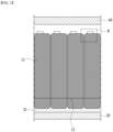
- FIG. 5 is a cross-sectional view of the battery module according to one embodiment of the present disclosure taken along the cutting line A-A' of FIG. 2 .
- FIG. 6 is an enlarged view of a section C of FIG. 5 .
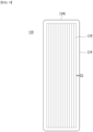
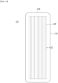
- FIG. 7 is a perspective view showing a battery cell included in a battery module according to one embodiment of the present disclosure.
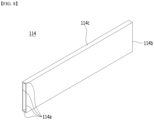
- FIG. 8 is a perspective view showing a battery case included in the battery cell of FIG. 7 .
- FIG. 9 is a cross-sectional view taken along the cutting line D-D' of FIG. 7 .
- the battery cell 110 included in the battery module 100 includes an electrode assembly 119; and a battery case 114 that is opened at its front and rear sides and houses the electrode assembly 119, wherein sealing portions 114sa and 114sb are formed on each of the front and rear surfaces of the battery case 114.
- the electrode assembly 119 may include a positive electrode, a negative electrode, and a separator disposed between the positive electrode and the negative electrode.
- the battery cell 110 is preferably a pouch-type battery cell, and can be formed in a rectangular sheet-like structure.
- the battery cell 110 according to the present embodiment has a structure in which two electrode leads 111 and 112 face each other and protrude from one end 114a and the other end 114b of the cell main body 113, respectively. That is, the battery cell 110 includes electrode leads 111 and 112 that are protruded in mutually opposite directions. More specifically, the electrode leads 111 and 112 are connected to an electrode assembly 119, and are protruded from the electrode assembly 119 to the outside of the battery cell 110.
- the battery cell 110 may include a battery case 114, wherein the battery case 114 may be opened at its front and rear surfaces.
- the battery case 114 may be a tubular case that is opened at its front and rear surfaces. Therefore, the electrode assembly 119 may be housed inside the battery case 114 through the front or rear surface of the battery case 114.
- the battery case 114 may be made of a laminate sheet including a resin layer and a metal layer.
- the battery case 114 may include both ends 114a and 114b and one side portion 114c connecting both ends 114a and 114b.
- one side portion 114c may be formed in both the upper and lower portions of the battery case 114 of FIG. 8 , but the one side portion 114c may represent the upper one side part 114c formed thereon. More specifically, the one side portion 114c may represent an upper surface of the battery case 114.
- both ends 114a and 114b of the battery case 114 can be formed in an opened shape, thus forming opened front and rear surfaces of the tubular case.
- the battery cell 110 can be produced by joining both ends 114a and 114b of a cell case 114 in a state in which an electrode assembly 119 is housed in a cell case 114.
- the battery cell 110 has a total of two sealing portions by adhering both ends 114a and 114b of the battery case 114, and the sealing portions 114sa and 114sb may have a structure that is sealed by a method such as heat sealing. Therefore, the battery cell 110 can be sealed by two sealing portions 114sa and 114sb.
- the front sealing portion 114sa and the rear sealing portion 114sb may be respectively formed so as to be adjacent to the electrode leads 111 and 112. After the electrode leads 111 and 112 are formed to protrude from the battery cell 110, the sealing portions 114sa and 114sb are formed to complete the sealing structure of the battery cell 110.
- Such a battery cell 110 may be formed by a plurality of numbers, and the plurality of battery cells 110 may be stacked so as to be electrically connected to each other, thereby forming a battery cell stack 120. Particularly, as shown in FIG. 4 , a plurality of battery cells 110 may be stacked along the direction parallel to the y-axis. Accordingly, the electrode leads 111 and 112 may protrude in the x-axis direction and the -x-axis direction, respectively.
- the conventional battery module had a problem that the cooling efficiency is reduced due to the space occupied by the sealing portion of the battery cell, and it is difficult to utilize the space when applying the thermally conductive resin layer to the upper portion.
- the battery cell 110 further comprises a second thermally conductive resin layer 320 located between the upper portion of the module frame 200 and the battery cell stack 120, and an upper portion of the battery cell stack 120 that contacts the second thermally conductive resin layer 320 may have a flat shape.
- the upper portion of the battery cell stack 120 may have a flat shape, wherein the flat shape may correspond to one side portion 114c of the battery cell 110. That is, one side portion 114c of the battery cell 110 is an integral portion of the tubular case, and is not formed with a sealing portion, and thus may be formed in a flat shape.
- the battery cell 110 of the battery module 100 is configured such that the sealing portions 114sa and 114sb are formed only on the front and rear surfaces of the battery case 114, except the one side portion 114c, thereby capable of minimizing a space occupied by the sealing portion.
- the space occupied by the sealing portion is minimized, the heat transfer resistance can be minimized and the cooling performance of the battery module can be improved.
- FIGS. 10 to 12 a battery cell included in a battery module according to another embodiment of the present disclosure will be described with reference to FIGS. 10 to 12 . Since the details of the battery module and battery cell overlap with the contents described above, only the contents different therefrom will be described.
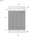
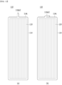
- FIG. 10 is a diagram showing a battery cell included in a battery module according to another embodiment of the present disclosure.
- FIG. 11 is a diagram showing the battery cell of FIG. 10 and a sealing part formed in the battery cell of FIG. 10 together.
- FIG. 12 is a view showing together another type of sealing portion formed in the battery cell of FIG. 10 .
- the battery cell 110 may be configured to form spaces G1 and G2 between the battery case 114 and the electrode assembly 119.
- a space G1 can be formed between the battery case 114 and the electrode assembly 119, but in the battery cell 110 according to the present embodiment, the space G2 between the battery case 114 and the electrode assembly 119 may be widened by a margin size in consideration of the insertion of the electrode assembly 119.
- a space G2 is formed between the battery case 114 and the electrode assembly 119 including the margin size in consideration of the insertion of the electrode assembly 119, whereby the efficiency can be increased, and the electrode assembly 119 can be easily inserted into the battery case 114.
- the space G2 between the battery case 114 and the electrode assembly 119 is minimized to prevent the electrode assembly 119 from moving inside the battery cell 110 and, at the same time, sealing portions 114sc1 and 114sc2 can be formed at one side portion 114c of the battery case 114 in order to maximize the cooling surface.
- the sealing portions 114sc1 and 114sc2 may be formed by compressing one side portion 114c of the battery case 114, and it may be formed by a heat-sealing method, similar to the front sealing portion 114sa and the rear sealing portion 114sb.
- the sealing portions 114sc1 and 114sc2 formed at one side portion 114c may be formed by protruding a part of the tubular case. That is, it may be a structure in which portions corresponding to the already closed areas are further protruded and crimped so as to protrude from the unopened one surface of the battery case, instead of adhering and sealing portions corresponding to the opened areas, similar to the front sealing portion 114sa and the rear sealing portion 114sb. Therefore, a part of the already closed battery case 114 is formed as the sealing portions 114sc1 and 114sc2, so that the sealing portions 114sc1 and 114sc2 formed at one side portion 114c can be used as a gas storage space of the battery cell 110.
- the sealing portion 114sc1 formed at one side portion 114c may be formed at an edge of the one side portion 114c. At this time, the sealing portion 114sc1 formed at the edge of the one side portion 114c may be formed protrusively from the one side portion 114c. The protruding sealing portion 114sc1 may be formed so as to be bent and adhered from the edge of the one side portion 114c toward the center of the one side portion 114c.
- the space G2 between the battery case 114 and the electrode assembly 119 is formed to include the margin size, not only can the electrode assembly 119 be fixed after the electrode assembly 119 is inserted, but also the cooling performance can be maintained and improved by minimizing the space occupied by the formation of the sealing portion 114sc1.
- the sealing portion 114sc2 formed at one side portion 114c may be formed at the center of the one side portion 114c.
- the sealing portion 114sc2 formed at the center of the one side portion 114c may be formed to protrude from the one side portion 114c.
- the protruding sealing portion 114sc2 may be formed so as to be bent and adhered from the center of the one side portion 114c toward the edge of the one side portion 114c. Therefore, the space occupied by the formation of the sealing portion 114sc1 can be minimized, thereby maintaining and improving the cooling performance.
- the battery case 114 is formed into a tubular case.
- the sealing portion is formed at one side portion 114c, the space occupied by the sealing portion can be minimized, thereby maximizing the cooling effect of the battery cell.
- a battery pack according to the present embodiment comprises the above-mentioned battery module.
- the battery pack of the present disclosure may have a structure in which one or more of the battery modules according to the present embodiment are gathered, and packed together with a battery management system (BMS) and a cooling device that control and manage battery's temperature, voltage, etc.
- BMS battery management system
- the battery pack can be applied to various devices.
- a device can be applied to a vehicle means such as an electric bicycle, an electric vehicle, or a hybrid vehicle, but the present disclosure is not limited thereto, and is applicable to various devices that can use a battery module, which is also falls under the scope of the present disclosure.
Landscapes
- Chemical & Material Sciences (AREA)
- Chemical Kinetics & Catalysis (AREA)
- Electrochemistry (AREA)
- General Chemical & Material Sciences (AREA)
- Engineering & Computer Science (AREA)
- Manufacturing & Machinery (AREA)
- Battery Mounting, Suspending (AREA)
- Secondary Cells (AREA)
Applications Claiming Priority (2)
| Application Number | Priority Date | Filing Date | Title |
|---|---|---|---|
| KR1020220007953A KR20230111915A (ko) | 2022-01-19 | 2022-01-19 | 전지 모듈 및 이를 포함하는 전지 팩 |
| PCT/KR2022/019768 WO2023140497A1 (fr) | 2022-01-19 | 2022-12-07 | Module de batterie et bloc-batterie le comprenant |
Publications (2)
| Publication Number | Publication Date |
|---|---|
| EP4376141A1 true EP4376141A1 (fr) | 2024-05-29 |
| EP4376141A4 EP4376141A4 (fr) | 2025-01-08 |
Family
ID=87348888
Family Applications (1)
| Application Number | Title | Priority Date | Filing Date |
|---|---|---|---|
| EP22922354.0A Pending EP4376141A4 (fr) | 2022-01-19 | 2022-12-07 | Module de batterie et bloc-batterie le comprenant |
Country Status (6)
| Country | Link |
|---|---|
| US (1) | US20240356101A1 (fr) |
| EP (1) | EP4376141A4 (fr) |
| JP (1) | JP7726597B2 (fr) |
| KR (1) | KR20230111915A (fr) |
| CN (1) | CN117897840A (fr) |
| WO (1) | WO2023140497A1 (fr) |
Family Cites Families (11)
| Publication number | Priority date | Publication date | Assignee | Title |
|---|---|---|---|---|
| KR101415575B1 (ko) * | 2011-10-18 | 2014-07-07 | 에스케이이노베이션 주식회사 | 이차 전지용 배터리 셀의 젤리 롤 랩핑 방법 |
| KR20160045468A (ko) * | 2014-10-17 | 2016-04-27 | 주식회사 엘지화학 | 파우치형 이차 전지 및 그의 제조방법 |
| DE102015110667B4 (de) * | 2015-07-02 | 2025-05-28 | Dr. Ing. H.C. F. Porsche Aktiengesellschaft | Zellenanordnung |
| CN208045659U (zh) * | 2016-12-06 | 2018-11-02 | Sk新技术株式会社 | 二次电池模块 |
| KR102128588B1 (ko) * | 2017-12-26 | 2020-07-08 | 에스케이이노베이션 주식회사 | 배터리 모듈 및 이의 제조 방법 |
| KR20200003600A (ko) * | 2018-07-02 | 2020-01-10 | 에스케이이노베이션 주식회사 | 배터리 모듈 |
| KR102382382B1 (ko) * | 2018-07-03 | 2022-04-01 | 주식회사 엘지에너지솔루션 | 열수축성 튜브를 포함하는 배터리 모듈 |
| KR102814054B1 (ko) * | 2019-07-23 | 2025-05-29 | 에스케이온 주식회사 | 배터리 모듈 |
| KR102715431B1 (ko) * | 2019-11-18 | 2024-10-08 | 주식회사 엘지에너지솔루션 | 전지 모듈 및 그 제조 방법 |
| US12294069B2 (en) * | 2020-04-22 | 2025-05-06 | Lg Energy Solution, Ltd. | Battery module and manufacturing method thereof |
| JP7538626B2 (ja) * | 2020-05-25 | 2024-08-22 | 本田技研工業株式会社 | 電池セル及び電池モジュール |
-
2022
- 2022-01-19 KR KR1020220007953A patent/KR20230111915A/ko active Pending
- 2022-12-07 CN CN202280059248.8A patent/CN117897840A/zh active Pending
- 2022-12-07 EP EP22922354.0A patent/EP4376141A4/fr active Pending
- 2022-12-07 US US18/683,589 patent/US20240356101A1/en active Pending
- 2022-12-07 WO PCT/KR2022/019768 patent/WO2023140497A1/fr not_active Ceased
- 2022-12-07 JP JP2024502668A patent/JP7726597B2/ja active Active
Also Published As
| Publication number | Publication date |
|---|---|
| US20240356101A1 (en) | 2024-10-24 |
| CN117897840A (zh) | 2024-04-16 |
| JP7726597B2 (ja) | 2025-08-20 |
| JP2024527420A (ja) | 2024-07-24 |
| WO2023140497A1 (fr) | 2023-07-27 |
| EP4376141A4 (fr) | 2025-01-08 |
| KR20230111915A (ko) | 2023-07-26 |
Similar Documents
| Publication | Publication Date | Title |
|---|---|---|
| US20240222781A1 (en) | Battery Module and Battery Pack Including the Same | |
| US20240170790A1 (en) | Battery module and battery pack including the same | |
| EP4318736A1 (fr) | Module de batterie et bloc-batterie le comprenant | |
| US20220393270A1 (en) | Battery module and battery pack including same | |
| US20220407139A1 (en) | Battery Module and Battery Pack Including the Same | |
| EP4181275B1 (fr) | Module de batterie et bloc-batterie le comprenant | |
| US20230402678A1 (en) | Battery Pack and Device Including the Same | |
| US12482877B2 (en) | Battery module and battery pack including the same | |
| EP4181292B1 (fr) | Bloc-batterie comprenant des modules de batterie | |
| US20250279503A1 (en) | Battery module and battery pack including the same | |
| US20230318078A1 (en) | Battery module and battery pack including the same | |
| EP4366038B1 (fr) | Module de batterie et bloc-batterie le comprenant | |
| EP4270603B1 (fr) | Module de batterie et bloc-batterie le comprenant | |
| EP4261985A1 (fr) | Bloc-batterie et dispositif le comprenant | |
| EP4376141A1 (fr) | Module de batterie et bloc-batterie le comprenant | |
| EP4300661B1 (fr) | Module de batterie et batterie le comprenant | |
| EP4243159A1 (fr) | Module de batterie et bloc-batterie le comprenant | |
| EP4175020A1 (fr) | Module de batterie et bloc-batterie le comprenant | |
| KR20230111916A (ko) | 전지 모듈 및 이를 포함하는 전지 팩 |
Legal Events
| Date | Code | Title | Description |
|---|---|---|---|
| STAA | Information on the status of an ep patent application or granted ep patent |
Free format text: STATUS: THE INTERNATIONAL PUBLICATION HAS BEEN MADE |
|
| PUAI | Public reference made under article 153(3) epc to a published international application that has entered the european phase |
Free format text: ORIGINAL CODE: 0009012 |
|
| STAA | Information on the status of an ep patent application or granted ep patent |
Free format text: STATUS: REQUEST FOR EXAMINATION WAS MADE |
|
| 17P | Request for examination filed |
Effective date: 20240222 |
|
| AK | Designated contracting states |
Kind code of ref document: A1 Designated state(s): AL AT BE BG CH CY CZ DE DK EE ES FI FR GB GR HR HU IE IS IT LI LT LU LV MC ME MK MT NL NO PL PT RO RS SE SI SK SM TR |
|
| A4 | Supplementary search report drawn up and despatched |
Effective date: 20241209 |
|
| RIC1 | Information provided on ipc code assigned before grant |
Ipc: H01M 10/6555 20140101ALI20241203BHEP Ipc: H01M 10/6553 20140101ALI20241203BHEP Ipc: H01M 10/653 20140101ALI20241203BHEP Ipc: H01M 10/613 20140101ALI20241203BHEP Ipc: H01M 50/183 20210101ALI20241203BHEP Ipc: H01M 50/538 20210101ALI20241203BHEP Ipc: H01M 50/533 20210101ALI20241203BHEP Ipc: H01M 10/04 20060101AFI20241203BHEP |
|
| DAV | Request for validation of the european patent (deleted) | ||
| DAX | Request for extension of the european patent (deleted) | ||
| STAA | Information on the status of an ep patent application or granted ep patent |
Free format text: STATUS: EXAMINATION IS IN PROGRESS |
|
| 17Q | First examination report despatched |
Effective date: 20250610 |