EP4376183A1 - Corps de boîtier de batterie et bloc-batterie - Google Patents
Corps de boîtier de batterie et bloc-batterie Download PDFInfo
- Publication number
- EP4376183A1 EP4376183A1 EP23163906.3A EP23163906A EP4376183A1 EP 4376183 A1 EP4376183 A1 EP 4376183A1 EP 23163906 A EP23163906 A EP 23163906A EP 4376183 A1 EP4376183 A1 EP 4376183A1
- Authority
- EP
- European Patent Office
- Prior art keywords
- box body
- folded edge
- wire harness
- voltage wire
- low
- Prior art date
- Legal status (The legal status is an assumption and is not a legal conclusion. Google has not performed a legal analysis and makes no representation as to the accuracy of the status listed.)
- Withdrawn
Links
Images


Classifications
-
- H—ELECTRICITY
- H01—ELECTRIC ELEMENTS
- H01M—PROCESSES OR MEANS, e.g. BATTERIES, FOR THE DIRECT CONVERSION OF CHEMICAL ENERGY INTO ELECTRICAL ENERGY
- H01M50/00—Constructional details or processes of manufacture of the non-active parts of electrochemical cells other than fuel cells, e.g. hybrid cells
- H01M50/20—Mountings; Secondary casings or frames; Racks, modules or packs; Suspension devices; Shock absorbers; Transport or carrying devices; Holders
- H01M50/204—Racks, modules or packs for multiple batteries or multiple cells
-
- H—ELECTRICITY
- H01—ELECTRIC ELEMENTS
- H01M—PROCESSES OR MEANS, e.g. BATTERIES, FOR THE DIRECT CONVERSION OF CHEMICAL ENERGY INTO ELECTRICAL ENERGY
- H01M50/00—Constructional details or processes of manufacture of the non-active parts of electrochemical cells other than fuel cells, e.g. hybrid cells
- H01M50/20—Mountings; Secondary casings or frames; Racks, modules or packs; Suspension devices; Shock absorbers; Transport or carrying devices; Holders
- H01M50/271—Lids or covers for the racks or secondary casings
-
- H—ELECTRICITY
- H01—ELECTRIC ELEMENTS
- H01M—PROCESSES OR MEANS, e.g. BATTERIES, FOR THE DIRECT CONVERSION OF CHEMICAL ENERGY INTO ELECTRICAL ENERGY
- H01M50/00—Constructional details or processes of manufacture of the non-active parts of electrochemical cells other than fuel cells, e.g. hybrid cells
- H01M50/20—Mountings; Secondary casings or frames; Racks, modules or packs; Suspension devices; Shock absorbers; Transport or carrying devices; Holders
- H01M50/298—Mountings; Secondary casings or frames; Racks, modules or packs; Suspension devices; Shock absorbers; Transport or carrying devices; Holders characterised by the wiring of battery packs
-
- Y—GENERAL TAGGING OF NEW TECHNOLOGICAL DEVELOPMENTS; GENERAL TAGGING OF CROSS-SECTIONAL TECHNOLOGIES SPANNING OVER SEVERAL SECTIONS OF THE IPC; TECHNICAL SUBJECTS COVERED BY FORMER USPC CROSS-REFERENCE ART COLLECTIONS [XRACs] AND DIGESTS
- Y02—TECHNOLOGIES OR APPLICATIONS FOR MITIGATION OR ADAPTATION AGAINST CLIMATE CHANGE
- Y02E—REDUCTION OF GREENHOUSE GAS [GHG] EMISSIONS, RELATED TO ENERGY GENERATION, TRANSMISSION OR DISTRIBUTION
- Y02E60/00—Enabling technologies; Technologies with a potential or indirect contribution to GHG emissions mitigation
- Y02E60/10—Energy storage using batteries
Definitions
- the disclosure relates to the technical field of batteries, in particular to a battery box body and a battery pack.
- a battery box body is configured to accommodate a battery assembly formed by a plurality of batteries to protect the batteries.
- wire harness assemblies connected to the battery assembly to satisfy different connection requirements.
- the structural limitations of the battery box body itself cause inconvenience in routing the wire harness assemblies.
- the disclosure provides a battery box body and a battery pack to improve the performance of the battery box body.
- a battery box body includes: a lower box body; a cover plate, which is connected to the lower box body, one end of the cover plate is bent to form a folded edge, and a receiving groove for accommodating a low-voltage wire harness is formed between the folded edge and the lower box body.
- the battery box body in an embodiment of the present disclosure includes a lower box body and a cover plate.
- the cover plate is connected to the lower box body.
- One end of the cover plate is bent to form a folded edge.
- a receiving groove for accommodating a low-voltage wire harness is formed between the folded edge and the lower box body so that the folded edge allows the low-voltage wire harness to pass through.
- the folded edge provides position-limiting protection for the low-voltage wire harness, thereby serving as a support structure for the low-voltage wire harness to provide protection for the low-voltage wire harness, and making it convenient to arrange routing of the low-voltage wire harness. That is, it may be ensured that the low-voltage wire harness may be routed in a relatively fixed position, thus improving the routing efficiency of the battery box body, and enhancing the performance of the battery box body.
- a battery pack in a second aspect of the present disclosure, includes the above-mentioned battery box body.
- the battery box body of the battery pack in an embodiment of the present disclosure includes a lower box body and a cover plate.
- the cover plate is connected to the lower box body.
- One end of the cover plate is bent to form a folded edge.
- a receiving groove for accommodating a low-voltage wire harness is formed between the folded edge and the lower box body so that the folded edge allows the low-voltage wire harness to pass through.
- the folded edge provides position-limiting protection for the low-voltage wire harness, thereby serving as a support structure for the low-voltage wire harness to provide protection for the low-voltage wire harness, and making it convenient to arrange routing of the low-voltage wire harness. That is, it may be ensured that the low-voltage wire harness may be routed in a relatively fixed position, thereby improving the routing efficiency of the battery box body, and enhancing the performance of the battery box body.
- first and second are only used for the purpose of description, and should not be construed as indicating or implying relative importance.
- plurality means two or more; the term “and/or” includes any and all combinations of one or more of associated items that are listed here.
- reference to “the/said” or “an” object is also intended to mean one of the possible plurality of such objects.
- connection may be a fixed connection, a detachable connection, an integral connection, or an electrical connection, or a signal connection.
- Connection can be direct connection or indirect connection established through an intermediary.
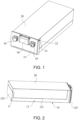
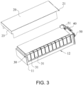
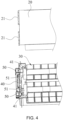
- the battery box body includes: a lower box body 10; a cover plate 20, the cover plate 20 is connected to the lower box body 10, one end of the cover plate 20 is bent to form a folded edge 21 for a low-voltage wire harness to pass through, and a receiving groove 22 for accommodating the low-voltage wire harness is formed between the folded edge 21 and the lower box body 10.
- the battery box body in an embodiment of the present disclosure includes a lower box body 10 and a cover plate 20.
- the cover plate 20 is connected to the lower box body 10.
- One end of the cover plate 20 is bent to form a folded edge 21.
- a receiving groove 22 for accommodating a low-voltage wire harness is formed between the folded edge 21 and the lower box body 10 so that the folded edge 21 allows the low-voltage wire harness to pass through.
- the folded edge 21 provides position-limiting protection for the low-voltage wire harness, thereby serving as a support structure for the low-voltage wire harness to provide protection for the low-voltage wire harness, and making it convenient to arrange routing of the low-voltage wire harness. That is, it may be ensured that the low-voltage wire harness may be routed in a relatively fixed position, thereby improving the routing efficiency of the battery box body, and enhancing the performance of the battery box body.
- the low-voltage wire harness may be configured to connect the battery and a BMS battery management module.
- the BMS battery management module may be located outside the battery box body. Therefore, a part of the low-voltage wire harness may be drawn out from the inside of the battery box body to facilitate connection with the BMS battery management module.
- the folded edge 21 is formed by bending one end of the cover plate 20, so that the low-voltage wire harness drawn from the inside of the battery box body is able to pass through the folded edge 21 to form a connection with the BMS battery management module.
- the low-voltage wire harness may be routed according to a predetermined path, and the low-voltage wire harness located outside the battery box body may be conveniently connected to the BMS battery management module, thereby improving the assembling efficiency of the battery pack.
- a receiving groove 22 for accommodating the low-voltage wire harness is formed between the folded edge 21 and the lower box body 10.
- the receiving groove 22 not only can serve as wiring storage for the low-voltage wire harness, but also limit the position of the low-voltage wire harness, so as to ensure that the low-voltage wire harness passes through the receiving groove 22 in a reliable manner, and prevent problems such as position deviation of the low-voltage wire harness, thereby ensuring that the low-voltage wire harness is reliably connected to the BMS battery management module.
- the receiving groove 22 is formed outside the battery box body, that is, the opening of the receiving groove 22 may communicate with the external environment.
- the receiving groove 22 is located inside the lower box body 10, that is, the folded edge 21 is located inside the lower box body 10, which not only facilitates the connection between the cover plate 20 and the lower box body 10, but also prevents the folded edge 21 from occupying too much space of the battery box body.
- the structure of the battery box body may be optimized to the greatest extent, and it is also convenient to arrange the routing of the low-voltage wire harness.
- the receiving groove 22 is located inside the lower box body 10, that is, the receiving groove 22 may be formed between the folded edge 21 and the inner side wall of the lower box body 10.
- the receiving groove 22 is located outside the lower box body 10, that is, the receiving groove 22 may be formed between the folded edge 21 and the outer side wall of the lower box body 10.
- the folded edge 21 may be bent downward relative to one end of the cover plate 20, for example, the folded edge 21 may be a flat plate, and the flat plate is bent downward relative to one end of the cover plate 20 and is opposite to a portion of the lower box body 10, thereby forming a substantially U-shaped receiving groove 22, so as to limit the position of the low-voltage wire harness for protection.
- the folded edge 21 includes a first segment 211 and a second segment 212.
- the first segment 211 is bent downward from one end of the cover plate 20, and the second segment 212 is connected to one end of the first segment 211 away from the cover plate 20, and is extended toward the inner side wall of the lower box body 10 to form the receiving groove 22 with the lower box body 10.
- the receiving groove 22 formed between the folded edge 21 and the lower box body 10 serves to limit the position of the low-voltage wire harness for protection.
- the folded edge 21 may be substantially L-shaped, that is, the first segment 211 and the second segment 212 are substantially L-shaped.
- the first segment 211 is bent downward from one end of the cover plate 20, and the second segment 212 is connected to one end of the first segment 211 away from the cover plate 20, and is extended toward the lower box body 10 so that one end of the second segment 212 may be arranged opposite to a portion of the lower box body 10, thereby forming a substantially U-shaped receiving groove 22, and the low-voltage wire harness is located in the U-shaped receiving groove 22, so as to ensure the routing stability of the low-voltage wire harness.
- At least part of the cover plate 20 is substantially parallel to the second segment 212, so that the volume of the receiving groove 22 is relatively large, and it is possible for the routing of the low-voltage wire harness in the receiving groove 22 to be relatively stable. In this way, the problem of long low-voltage wire harness may be avoided to some extent.
- At least a part of the cover plate 20 is substantially perpendicular to the first segment 211, that is, the first segment 211 and the second segment 212 are substantially perpendicular, and the first segment 211 and the second segment 212 substantially form an L-shaped structure for the low-voltage wire harness to pass through, and may serve to protect the low-voltage wire harness while being able to isolate the low-voltage wire harness from other wire harness, for example, to isolate the low-voltage wire harness from high-voltage wire harness, thereby avoiding the interference of the high-voltage signal on the low-voltage signal.
- the lower box body 10 includes a base plate 11 and a main frame 12.
- the main frame 12 is connected to the base plate 11, and the main frame 12 includes a first end plate 122 and a second end plate 123.
- the first end plate 122 and the second end plate 123 are oppositely connected to the base plate 11, and the cover plate 20 is bent towards one end of the second end plate 123 to form a folded edge 21, so that the receiving groove 22 is formed between the folded edge 21 and the second end plate 123 in order to accommodate the low-voltage wire harness and serve as a reliable protection for the low-voltage wire harness.
- the BMS battery management module may be arranged on the second end plate 123.
- the first end plate 122 and the second end plate 123 are oppositely arranged on the base plate 11, and the main frame 12 may further include two opposite side plates 121.
- the two opposite side plates 121 are conveniently connected to two opposite ends of the base plate 11, so that a receiving space is formed between the first end plate 122 and the second end plate 123.
- a chamber for accommodating the battery is formed as an effective protection for the battery.
- the second end plate 123 is detachably connected to the main frame 12.
- the cover plate 20 is bent toward the other end of the first end plate 122 to form a butt flange 23, and the butt flange 23 is connected to the first end plate 122, so that the cover plate 20 is reliably fixed on the main frame 12 to ensure the connection stability of the cover plate 20.
- the opposite sides of the cover plate 20 form a folded edge 21 and a butt flange 23 respectively.
- the butt flange 23 is connected to the first end plate 122, and a receiving groove 22 is formed between the folded edge 21 and the second end plate 123, so that the low-voltage wire harness is located between the folded edge 21 and the second end plate 123 to serve as reliable protection for the low-voltage wire harness.
- a receiving groove 22 is formed between the folded edge 21 and the second end plate 123, that is, the first segment 211 of the folded edge 21 is bent downward from one end of the cover plate 20, and the second segment 212 of the folded edge 21 is connected to one end of the first segment 211 away from the cover plate 20 and extends towards the inner side wall of the second end plate 123, thereby forming the receiving groove 22.
- the cover plate 20 itself is relatively simple, it is easier for the cover plate 20 to form a folded edge 21, and it is also convenient to complete the connection between the cover plate 20 and the lower box body 10 subsequently. Moreover, when the battery pack is assembled, the cover plate 20 may be the last component to be assembled. Therefore, the folded edge 21 of the cover plate 20 will not affect the assembling of other components, thereby improving the assembling efficiency of the battery pack.
- the folded edge 21 is connected to the second end plate 123, so as to improve the connection stability between the cover plate 20 and the lower box body 10, and the second end plate 123 may provide reliable support for the folded edge 21, preventing the folded edge 21 from being deformed, thereby improving the structural stability of the folded edge 21.
- the second segment 212 of the folded edge 21 may be placed on the top of the second end plate 123, so that the second end plate 123 forms a support for the folded edge 21.
- the cover plate 20 is assembled, it is also possible for the second end plate 123 to reliably position the cover plate 20, thereby improving the assembling efficiency of the cover plate 20.
- the folded edge 21 is detachably connected to the second end plate 123, which not only facilitates the assembling of the folded edge 21 and the second end plate 123, but also facilitates the subsequent maintenance of the battery pack, thereby improving the service life of the battery pack.
- the folded edge 21 and the second end plate 123 may be connected by fasteners.
- the folded edge 21 may be connected to the second end plate 123 by screws. In this way, not only that the connection method is simple, but also the assembling is easy and disassembly may be carried out conveniently in subsequent process.
- the folded edge 21 and the second end plate 123 may be connected by multiple fasteners, which is not limited here.
- the folded edge 21 is engaged with the second end plate 123, which not only facilitates the connection, but also facilitates the disassembly of the folded edge 21 and the second end plate 123.
- the folded edge 21 and the second end plate 123 may be engaged with each other through convex and concaves, which is not limited here.
- the second end plate 123 may be integrally formed with the main frame 12.
- the folded edge 21 is disposed on the cover plate 20
- the receiving groove 22 is formed through the folded edge 21 and the second end plate 123
- the second end plate 123 may provide a supporting surface for the folded edge 21 and form a side wall of the receiving groove 22. In this way, the second end plate 123 will not interfere with other structures in the battery box body, thereby facilitating the assembling of the battery pack.
- the receiving groove 22 may be formed between the folded edge 21 and the main frame 12.
- An embodiment of the present disclosure further provides a battery pack, which includes the above-mentioned battery box body.
- the battery box body of the battery pack in an embodiment of the present disclosure includes a lower box body 10 and a cover plate 20.
- the cover plate 20 is connected to the lower box body 10.
- One end of the cover plate 20 is bent to form a folded edge 21.
- a receiving groove 22 for accommodating a low-voltage wire harness is formed between the folded edge 21 and the lower box body 10 so that the folded edge 21 allows the low-voltage wire harness to pass through.
- the folded edge 21 provides position-limiting protection for the low-voltage wire harness, thereby serving as a support structure for the low-voltage wire harness to provide protection for the low-voltage wire harness, and making it convenient to arrange routing of the low-voltage wire harness. That is, it may be ensured that the low-voltage wire harness may be routed in a relatively fixed position, thereby improving the routing efficiency of the battery box body, and enhancing the performance of the battery box body.
- the battery pack further includes: a battery assembly 30, the battery assembly 30 is arranged in the lower box body 10, and the battery assembly 30 includes a plurality of single cells 31; a BMS battery management module 40, the BMS battery management module 40 is set on the lower box body 10; a low-voltage wire harness 41, the low-voltage wire harness 41 connects the battery assembly 30 and the BMS battery management module 40, and a part of the low-voltage wire harness 41 is set on the folded edge 21, so that a part of the low-voltage wire harness 41 may form an electrical connection with the BMS battery management module 40 through the folded edge 21.
- the BMS battery management module 40 is configured to obtain voltage information, temperature information, etc. of the battery assembly 30.
- the low-voltage wire harness 41 may include a circuit board, and the circuit board may be arranged above the battery assembly 30 to form a connection with a plurality of single cells 31, so as to obtain voltage information and temperature information of the single cells 31, etc.
- the low-voltage wire harness 41 may also include a connecting wire harness, which may be connected to a connector of the circuit board.
- the connecting wire harness is electrically connected to the BMS battery management module 40 through the folded edge 21.
- the connecting wire harness may be a wire.
- the battery pack further includes: a high-voltage connector 50 disposed on the lower box body 10; a high-voltage wire harness 51 connecting the battery assembly 30 and the high-voltage connector 50, the high-voltage wire harness 51 is located below the folded edge 21, so that the folded edge 21 isolates the low-voltage wire harness from the high-voltage wire harness 51. That is to say, the folded edge 21 may form electromagnetic shielding, thereby avoiding interference of high-voltage signals to low-voltage signals.
- the cover plate 20 is made of metal, that is, the folded edge 21 is made of metal, and the folded edge 21 isolates the low-voltage wire harness from the high-voltage wire harness 51, so that the interference of the high-voltage signal to the low-voltage signal may be avoided through electromagnetic shielding. In this way, it is possible to ensure the performance of the battery pack, and the problem of chaotic signal or weak signal may be avoided.
- the high-voltage connector 50 may be used as the charging and discharging connection ends of the battery pack. There may be two high-voltage connectors 50, and the two high-voltage connectors 50 may be the positive terminal and the negative terminal.
- the BMS battery management module 40 may be substantially located between two high-voltage connectors 50, as shown in FIG. 1 .
- At least one of the cover plate 20 and the folded edge 21 is provided with a through hole 24 for the low-voltage wire harness to pass through and to be formed on the folded edge 21 for connection with the BMS battery management module 40.
- the low-voltage wire harness configured to pass through the through hole 24 may be a wire, so as to pass through the through hole 24 and enter the receiving groove 22 formed by the folded edge 21 and the lower box body 10.
- the engagement of the low-voltage wire harness and the folded edge 21 not only facilitates to fix the folded edge 21, but also ensures that the low-voltage wire harness is reliably fixed on the folded edge 21.
- the low-voltage wire harness and the folded edge 21 may be engaged through the buckle provided on the folded edge 21.
- the low-voltage wire harness is insulated from the folded edge 21, for example, the folded edge 21 may be coated with a coating, such as aluminum oxide (Al 2 O 3 ), zirconia (ZrO 2 ) and other ceramic materials.
- the low-voltage wire harness is engaged with the folded edge 21, and the receiving groove 22 may be formed between the folded edge 21 and the second end plate 123, and the low-voltage wire harness is located in the receiving groove 22. In this way, it is possible to provide reliable protection for the low-voltage wire harness and improve the safety and performance of the battery pack.
- a plurality of single cells 31 may be fixed through end plates and side plates to form a battery module, and the battery module is placed into the battery box body.
- the plurality of single cells 31 may be directly arranged in the battery box body, that is, there is no need to assemble the plurality of single cells 31 into a group, in which case, the end plates and side plates may be removed.
- the single cell 31 includes a core and an electrolyte, the minimum unit capable of performing an electrochemical reaction such as charging/discharging.
- the core refers to a unit formed by winding or laminating a stacked portion, and the stacked portion includes a first electrode, a separator, and a second electrode. When the first electrode is a positive electrode, the second electrode is a negative electrode. The polarities of the first electrode and the second electrode may be switched.
- the core is set in the battery housing.
- the single cell 31 is a laminated battery, which is not only convenient for grouping, but also may be processed to obtain a longer battery.
- the core is a laminated core, and the core has first electrode sheets stacked on one another, second electrode sheets electrically opposite to the first electrode sheets, and a diaphragm disposed between the first electrode sheet and the second electrode sheet, so that multiple pairs of the first electrode sheets and the second electrode sheets are stacked to form a laminated core.
- the single cell 31 may be a wound battery, that is, a first electrode sheet, a second electrode sheet electrically opposite to the first electrode sheet, and a diaphragm arranged between the first electrode sheet and the second electrode sheet are wound to obtain a wound core.
- a plurality of folded edges 21 may be formed on the cover plate 20, and the plurality of folded edges 21 may respectively correspond to a plurality of battery assemblies 30.
- Each battery assembly 30 is able to isolate the high-voltage wire harness from the low-voltage wire harness through the corresponding folded edge 21. In this way, it is possible to avoid signal interference between high-voltage signals and low-voltage signals to ensure the performance of the battery pack.
Landscapes
- Chemical & Material Sciences (AREA)
- Chemical Kinetics & Catalysis (AREA)
- Electrochemistry (AREA)
- General Chemical & Material Sciences (AREA)
- Battery Mounting, Suspending (AREA)
Applications Claiming Priority (1)
| Application Number | Priority Date | Filing Date | Title |
|---|---|---|---|
| CN202211478330.2A CN115911723B (zh) | 2022-11-23 | 2022-11-23 | 电池箱体及电池包 |
Publications (1)
| Publication Number | Publication Date |
|---|---|
| EP4376183A1 true EP4376183A1 (fr) | 2024-05-29 |
Family
ID=85726410
Family Applications (1)
| Application Number | Title | Priority Date | Filing Date |
|---|---|---|---|
| EP23163906.3A Withdrawn EP4376183A1 (fr) | 2022-11-23 | 2023-03-24 | Corps de boîtier de batterie et bloc-batterie |
Country Status (2)
| Country | Link |
|---|---|
| EP (1) | EP4376183A1 (fr) |
| CN (1) | CN115911723B (fr) |
Citations (3)
| Publication number | Priority date | Publication date | Assignee | Title |
|---|---|---|---|---|
| US20120328919A1 (en) * | 2011-06-01 | 2012-12-27 | Elringklinger Ag | Conduit system for connecting a plurality of voltage tapping points and/or temperature measuring points of an electro-chemical device to a monitoring unit |
| US20210175586A1 (en) * | 2016-01-29 | 2021-06-10 | Gs Yuasa International Ltd. | Energy storage apparatus |
| EP4050714A1 (fr) * | 2019-10-23 | 2022-08-31 | GS Yuasa International Ltd. | Dispositif accumulateur électrique |
Family Cites Families (3)
| Publication number | Priority date | Publication date | Assignee | Title |
|---|---|---|---|---|
| KR102884186B1 (ko) * | 2019-12-16 | 2025-11-13 | 주식회사 엘지에너지솔루션 | 홀드다운 브라켓을 포함하는 전지 팩 및 이를 포함하는 디바이스 |
| CN214043898U (zh) * | 2020-12-24 | 2021-08-24 | 湖北亿纬动力有限公司 | 电池箱体以及电池包 |
| CN218586217U (zh) * | 2022-11-23 | 2023-03-07 | 中创新航科技股份有限公司 | 电池箱体及电池包 |
-
2022
- 2022-11-23 CN CN202211478330.2A patent/CN115911723B/zh active Active
-
2023
- 2023-03-24 EP EP23163906.3A patent/EP4376183A1/fr not_active Withdrawn
Patent Citations (3)
| Publication number | Priority date | Publication date | Assignee | Title |
|---|---|---|---|---|
| US20120328919A1 (en) * | 2011-06-01 | 2012-12-27 | Elringklinger Ag | Conduit system for connecting a plurality of voltage tapping points and/or temperature measuring points of an electro-chemical device to a monitoring unit |
| US20210175586A1 (en) * | 2016-01-29 | 2021-06-10 | Gs Yuasa International Ltd. | Energy storage apparatus |
| EP4050714A1 (fr) * | 2019-10-23 | 2022-08-31 | GS Yuasa International Ltd. | Dispositif accumulateur électrique |
Also Published As
| Publication number | Publication date |
|---|---|
| CN115911723A (zh) | 2023-04-04 |
| CN115911723B (zh) | 2026-02-13 |
Similar Documents
| Publication | Publication Date | Title |
|---|---|---|
| EP2562842B1 (fr) | Module de batterie | |
| KR102870559B1 (ko) | 전지 셀, 전지, 전기 장치, 전지 셀의 제조 방법 및 시스템 | |
| EP2315297A1 (fr) | Support de barre omnibus et bloc-batteries l'incluant | |
| CN114503355A (zh) | 二次电池、电池模块以及使用二次电池作为电源的装置 | |
| EP3800701B1 (fr) | Module de batterie | |
| JP2005332823A (ja) | 二次電池とこれを利用した電池モジュール | |
| CN114784465A (zh) | 电池、电池的装配方法及电池组 | |
| CN116097517B (zh) | 电池、用电设备和电池的制备方法 | |
| US12463300B2 (en) | Electricity storage device and electricity storage module | |
| US11929510B2 (en) | Secondary battery and manufacturing method thereof, battery module, and apparatus | |
| US11862817B2 (en) | Energy storage apparatus | |
| CN218586217U (zh) | 电池箱体及电池包 | |
| CN116632427A (zh) | 电池 | |
| CN222896759U (zh) | 电池及用电装置 | |
| CN217086806U (zh) | 电池及电池组 | |
| CN216850164U (zh) | 一种电池装置 | |
| CN217114627U (zh) | 电池和用电装置 | |
| EP4376183A1 (fr) | Corps de boîtier de batterie et bloc-batterie | |
| CN114725477A (zh) | 电芯单元、电池及电池的装配方法 | |
| CN220368109U (zh) | 电池组 | |
| WO2025031495A1 (fr) | Structure de connexion de module et batterie d'alimentation | |
| CN216980648U (zh) | 电芯单元及电池 | |
| CN217239531U (zh) | 电池及电池组 | |
| CN115084626A (zh) | 一种电池装置装配方法及电池装置 | |
| US20250300302A1 (en) | Electricity storage cell |
Legal Events
| Date | Code | Title | Description |
|---|---|---|---|
| PUAI | Public reference made under article 153(3) epc to a published international application that has entered the european phase |
Free format text: ORIGINAL CODE: 0009012 |
|
| STAA | Information on the status of an ep patent application or granted ep patent |
Free format text: STATUS: REQUEST FOR EXAMINATION WAS MADE |
|
| 17P | Request for examination filed |
Effective date: 20230324 |
|
| AK | Designated contracting states |
Kind code of ref document: A1 Designated state(s): AL AT BE BG CH CY CZ DE DK EE ES FI FR GB GR HR HU IE IS IT LI LT LU LV MC ME MK MT NL NO PL PT RO RS SE SI SK SM TR |
|
| STAA | Information on the status of an ep patent application or granted ep patent |
Free format text: STATUS: THE APPLICATION IS DEEMED TO BE WITHDRAWN |
|
| 18D | Application deemed to be withdrawn |
Effective date: 20241130 |