EP4376200A1 - Batteriepack, batteriemodul und fahrzeug damit - Google Patents
Batteriepack, batteriemodul und fahrzeug damit Download PDFInfo
- Publication number
- EP4376200A1 EP4376200A1 EP23843269.4A EP23843269A EP4376200A1 EP 4376200 A1 EP4376200 A1 EP 4376200A1 EP 23843269 A EP23843269 A EP 23843269A EP 4376200 A1 EP4376200 A1 EP 4376200A1
- Authority
- EP
- European Patent Office
- Prior art keywords
- pouch
- cell
- type battery
- cover
- battery cell
- Prior art date
- Legal status (The legal status is an assumption and is not a legal conclusion. Google has not performed a legal analysis and makes no representation as to the accuracy of the status listed.)
- Granted
Links
Images


Classifications
-
- H—ELECTRICITY
- H01—ELECTRIC ELEMENTS
- H01M—PROCESSES OR MEANS, e.g. BATTERIES, FOR THE DIRECT CONVERSION OF CHEMICAL ENERGY INTO ELECTRICAL ENERGY
- H01M50/00—Constructional details or processes of manufacture of the non-active parts of electrochemical cells other than fuel cells, e.g. hybrid cells
- H01M50/30—Arrangements for facilitating escape of gases
- H01M50/35—Gas exhaust passages comprising elongated, tortuous or labyrinth-shaped exhaust passages
- H01M50/367—Internal gas exhaust passages forming part of the battery cover or case; Double cover vent systems
-
- H—ELECTRICITY
- H01—ELECTRIC ELEMENTS
- H01M—PROCESSES OR MEANS, e.g. BATTERIES, FOR THE DIRECT CONVERSION OF CHEMICAL ENERGY INTO ELECTRICAL ENERGY
- H01M10/00—Secondary cells; Manufacture thereof
- H01M10/60—Heating or cooling; Temperature control
- H01M10/65—Means for temperature control structurally associated with the cells
- H01M10/658—Means for temperature control structurally associated with the cells by thermal insulation or shielding
-
- H—ELECTRICITY
- H01—ELECTRIC ELEMENTS
- H01M—PROCESSES OR MEANS, e.g. BATTERIES, FOR THE DIRECT CONVERSION OF CHEMICAL ENERGY INTO ELECTRICAL ENERGY
- H01M50/00—Constructional details or processes of manufacture of the non-active parts of electrochemical cells other than fuel cells, e.g. hybrid cells
- H01M50/10—Primary casings; Jackets or wrappings
- H01M50/102—Primary casings; Jackets or wrappings characterised by their shape or physical structure
- H01M50/105—Pouches or flexible bags
-
- H—ELECTRICITY
- H01—ELECTRIC ELEMENTS
- H01M—PROCESSES OR MEANS, e.g. BATTERIES, FOR THE DIRECT CONVERSION OF CHEMICAL ENERGY INTO ELECTRICAL ENERGY
- H01M50/00—Constructional details or processes of manufacture of the non-active parts of electrochemical cells other than fuel cells, e.g. hybrid cells
- H01M50/20—Mountings; Secondary casings or frames; Racks, modules or packs; Suspension devices; Shock absorbers; Transport or carrying devices; Holders
- H01M50/204—Racks, modules or packs for multiple batteries or multiple cells
- H01M50/207—Racks, modules or packs for multiple batteries or multiple cells characterised by their shape
- H01M50/211—Racks, modules or packs for multiple batteries or multiple cells characterised by their shape adapted for pouch cells
-
- H—ELECTRICITY
- H01—ELECTRIC ELEMENTS
- H01M—PROCESSES OR MEANS, e.g. BATTERIES, FOR THE DIRECT CONVERSION OF CHEMICAL ENERGY INTO ELECTRICAL ENERGY
- H01M50/00—Constructional details or processes of manufacture of the non-active parts of electrochemical cells other than fuel cells, e.g. hybrid cells
- H01M50/20—Mountings; Secondary casings or frames; Racks, modules or packs; Suspension devices; Shock absorbers; Transport or carrying devices; Holders
- H01M50/233—Mountings; Secondary casings or frames; Racks, modules or packs; Suspension devices; Shock absorbers; Transport or carrying devices; Holders characterised by physical properties of casings or racks, e.g. dimensions
- H01M50/24—Mountings; Secondary casings or frames; Racks, modules or packs; Suspension devices; Shock absorbers; Transport or carrying devices; Holders characterised by physical properties of casings or racks, e.g. dimensions adapted for protecting batteries from their environment, e.g. from corrosion
-
- H—ELECTRICITY
- H01—ELECTRIC ELEMENTS
- H01M—PROCESSES OR MEANS, e.g. BATTERIES, FOR THE DIRECT CONVERSION OF CHEMICAL ENERGY INTO ELECTRICAL ENERGY
- H01M50/00—Constructional details or processes of manufacture of the non-active parts of electrochemical cells other than fuel cells, e.g. hybrid cells
- H01M50/20—Mountings; Secondary casings or frames; Racks, modules or packs; Suspension devices; Shock absorbers; Transport or carrying devices; Holders
- H01M50/249—Mountings; Secondary casings or frames; Racks, modules or packs; Suspension devices; Shock absorbers; Transport or carrying devices; Holders specially adapted for aircraft or vehicles, e.g. cars or trains
-
- H—ELECTRICITY
- H01—ELECTRIC ELEMENTS
- H01M—PROCESSES OR MEANS, e.g. BATTERIES, FOR THE DIRECT CONVERSION OF CHEMICAL ENERGY INTO ELECTRICAL ENERGY
- H01M50/00—Constructional details or processes of manufacture of the non-active parts of electrochemical cells other than fuel cells, e.g. hybrid cells
- H01M50/20—Mountings; Secondary casings or frames; Racks, modules or packs; Suspension devices; Shock absorbers; Transport or carrying devices; Holders
- H01M50/271—Lids or covers for the racks or secondary casings
-
- H—ELECTRICITY
- H01—ELECTRIC ELEMENTS
- H01M—PROCESSES OR MEANS, e.g. BATTERIES, FOR THE DIRECT CONVERSION OF CHEMICAL ENERGY INTO ELECTRICAL ENERGY
- H01M50/00—Constructional details or processes of manufacture of the non-active parts of electrochemical cells other than fuel cells, e.g. hybrid cells
- H01M50/30—Arrangements for facilitating escape of gases
- H01M50/383—Flame arresting or ignition-preventing means
-
- H—ELECTRICITY
- H01—ELECTRIC ELEMENTS
- H01M—PROCESSES OR MEANS, e.g. BATTERIES, FOR THE DIRECT CONVERSION OF CHEMICAL ENERGY INTO ELECTRICAL ENERGY
- H01M2220/00—Batteries for particular applications
- H01M2220/20—Batteries in motive systems, e.g. vehicle, ship, plane
-
- Y—GENERAL TAGGING OF NEW TECHNOLOGICAL DEVELOPMENTS; GENERAL TAGGING OF CROSS-SECTIONAL TECHNOLOGIES SPANNING OVER SEVERAL SECTIONS OF THE IPC; TECHNICAL SUBJECTS COVERED BY FORMER USPC CROSS-REFERENCE ART COLLECTIONS [XRACs] AND DIGESTS
- Y02—TECHNOLOGIES OR APPLICATIONS FOR MITIGATION OR ADAPTATION AGAINST CLIMATE CHANGE
- Y02E—REDUCTION OF GREENHOUSE GAS [GHG] EMISSIONS, RELATED TO ENERGY GENERATION, TRANSMISSION OR DISTRIBUTION
- Y02E60/00—Enabling technologies; Technologies with a potential or indirect contribution to GHG emissions mitigation
- Y02E60/10—Energy storage using batteries
Definitions
- the present disclosure relates to a battery pack, a battery module, and a vehicle including the same, and more specifically, to a battery pack having excellent safety against thermal events, a battery module, and a vehicle including the same.
- the present application claims priority to Korean Patent Application No. 10-2022-0089574 filed on July 20, 2022 and Korean Patent Application No. 10-2023-0036122 filed on March 20, 2023 , the disclosures of which are incorporated herein by reference.
- Nickel cadmium batteries or nickel hydrogen batteries have been widely used as conventional secondary batteries, but recently, lithium secondary batteries having advantages of free charge/discharge, very low self-discharge rate, and high energy density due to little memory effect compared to nickel-based secondary batteries, are widely used.
- Such lithium secondary batteries mainly use a lithium-based oxide and a carbon material as a positive electrode active material and a negative electrode active material, respectively.
- Lithium secondary batteries include an electrode assembly in which a positive electrode plate and a negative electrode plate coated with the positive electrode active material and the negative electrode active material, respectively, are disposed with a separator therebetween, and an exterior material that seals and accommodates the electrode assembly together with an electrolyte, that is, a battery case.
- lithium secondary batteries may be classified into can-type secondary batteries in which electrode assemblies are embedded in a metal can and pouch-type secondary batteries in which electrode assemblies are embedded in a pouch of aluminum laminate sheets, depending on the shape of an exterior material.
- a conventional battery pack includes one or more battery modules inside a pack case and a control unit that controls charge/discharge of the battery pack, such as a battery management system (BMS).
- BMS battery management system
- the battery module is configured to include a plurality of battery cells inside a module case. That is, in the case of a conventional battery pack, a plurality of battery cells (secondary batteries) are accommodated inside a module case to form each battery module, and one or more of these battery modules are accommodated inside the pack case to form a battery pack.
- pouch-type batteries have advantages in various aspects, such as light weight and less dead space when stacked, but are problematic in that they are vulnerable to external impact and somewhat inferior in assemblability. Therefore, it is common for a battery pack to be manufactured by first modularizing a plurality of cells and then accommodating them inside a pack case.
- conventional battery packs may be disadvantageous in terms of energy density, assemblability, cooling, and the like due to modularization.
- the volume of the battery pack may be unnecessarily increased or the space occupied by the battery cells may be reduced due to various components such as the module case or stacking frame.
- a battery module is first configured by modularizing a plurality of battery cells and then the battery module is accommodated in a pack case, whereby there is a problem that the manufacturing process of the battery pack becomes complicated.
- the cooling efficiency may be reduced and the cooling structure may also be complicated.
- thermal runaway, ignition, or explosion occurs in some cells within any one battery module, the generated high-temperature gas, flame, or high-temperature internal material may be ejected and thermally propagated to other adjacent battery modules, thereby causing secondary thermal runaway, secondary fire, or explosion, and thus there is a concern that a chain of thermal runaway, ignition, or explosion may occur in cells within the plurality of battery modules. Therefore, there is a great need for a means capable of suppressing or delaying flame transfer between battery modules when a thermal event such as thermal runaway occurs.
- conventional battery packs or battery modules may be vulnerable to thermal events. In particular, if a thermal event occurs inside a battery module or battery pack, a thermal runaway may occur, resulting in flames and, in severe cases, even explosion.
- the present disclosure is designed to solve the problems of the related art, and therefore the present disclosure is directed to providing a battery pack having excellent energy density, assemblability and/or coolability, a battery module, and a vehicle including the same.
- the present disclosure is also directed to providing a battery pack capable of ensuring excellent safety in the event of a thermal event, a battery module, and a vehicle including the same.
- a battery pack includes a plurality of pouch-type battery cells having a receiving portion in which an electrode assembly is accommodated and an edge portion around the receiving portion; a pack case that accommodates the pouch-type battery cell in an upright state by placing the edge portion of the pouch-type battery cell downward in the internal space; and a cell cover that at least partially surrounds at least some of the pouch-type battery cells among the plurality of pouch-type battery cells in the internal space of the pack case, thereby surrounding the upper edge portion of the pouch-type battery cell and exposing the lower edge portion of the pouch-type battery cell, wherein the cell cover has a separation space between the cell cover and the upper edge portion of the wrapped pouch-type battery cell, wherein a pocket structure for restricting the movement of gas emitted from the pouch-type battery cell in the horizontal direction and upward across the upper edge portion within the separation space is provided on the cell cover.
- the pocket structure may divide the separation space into two or more spaces communicating with each other, and may restrict the movement of the gas between the divided spaces.
- the cell cover may include an upper cover portion configured to surround the top of the upper edge portion of the pouch-type battery cell; and a side cover portion extending downward from one end of the upper cover portion and surrounding the outside of one side receiving portion of the wrapped pouch-type battery cell.
- the cell cover may have the upper cover portion formed in multiple layers.
- the cell cover may include two unit covers with upper ends bent toward each other.
- the two unit covers may be laid over in the vertical direction with their bent ends at least partially spaced apart.
- the two unit covers may include a first cover configured to surround the left surface and one edge of the wrapped pouch-type battery cell, and a second cover configured to surround the right surface and the other edge of the wrapped pouch-type battery cell.
- the first cover may include a first upper cover portion configured to surround the top of an upper edge portion of the pouch-type battery cell, and a first side cover portion extending downward from one end of the first upper cover portion and surrounding the outside of one side receiving portion of the wrapped pouch-type battery cell
- the second cover may include a second upper cover portion configured to surround the top of an upper edge portion of the pouch-type battery cell, and a second side cover portion extending downward from one end of the second upper cover portion and surrounding the outside of the other side receiving portion of the wrapped pouch-type battery cell, wherein the second upper cover portion may be spaced apart upward from the first upper cover portion.
- the second upper cover portion may cover the first upper cover portion and extend to the first side cover portion.
- first upper cover portion and the second upper cover portion may have a first portion covering the pouch-type battery cell, and a second portion having a surface direction different from that of the first portion.
- the first portion may be inclined downward.
- the second portion may be connected to an end of the first portion and be bent downward to form a blocking portion.
- the blocking portion of the second upper cover portion covers the first side cover portion.
- each of the two unit covers is configured in a form of bending one plate.
- the cell cover may induce the gas to flow downward.
- the first side cover portion and the pouch-type battery cell may be bonded, and the second side cover portion and the pouch-type battery cell may be bonded.
- the second side cover portion may have a longer length in the vertical direction compared to the first side cover portion.
- the pack case may include a discharge hole for discharging the gas at the bottom, and the discharge hole may communicate with the separation space.
- the cell cover may include an insulating coating layer on the inner surface.
- the battery pack according to the present disclosure may also further include a control module accommodated in the internal space of the pack case and configured to control charge/discharge of the pouch-type battery cell.
- a battery module is a battery module, one or more of which are accommodated in the internal space of the pack case, and includes a plurality of pouch-type battery cells having a receiving portion in which an electrode assembly is accommodated and an edge portion around the receiving portion; a module case that accommodates the pouch-type battery cell in an upright state by placing the edge portion of the pouch-type battery cell downward in the internal space; and a cell cover that at least partially surrounds at least some of the pouch-type battery cells among the plurality of pouch-type battery cells in the internal space of the module case, thereby surrounding the upper edge portion of the pouch-type battery cell and exposing the lower edge portion of the pouch-type battery cell, wherein the cell cover has a separation space between the cell cover and the upper edge portion of the wrapped pouch-type battery cell, wherein a pocket structure for restricting the movement of gas emitted from the pouch-type battery cell in the horizontal direction and upward across the upper edge portion within the separation space is provided on the cell cover.
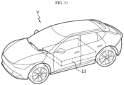
- a vehicle according to still another aspect of the present disclosure may include a battery pack according to the present disclosure.
- a battery pack with a cell to pack (CTP) concept is provided, and a module case or the like is eliminated in such a battery pack, thereby improving cooling performance and energy density.
- CTP cell to pack
- a plurality of pouch-type battery cells may be stably accommodated inside a pack case without the configuration of a stacking frame such as a plastic cartridge or a separate module case.
- the energy density of a battery pack may be improved.
- the battery cells are directly accommodated in the pack case without being modularized, and thus a battery pack that does not require a module case for the battery module may be manufactured. Accordingly, by reducing the space occupied by the module case, more and more battery cells may be disposed inside the pack case. Therefore, there is an effect of further improving the energy density of the battery pack. Pouch-type battery cells may be directly assembled to the pack case of the battery pack, thereby maximizing space utilization of the battery pack and significantly improving energy capacity.
- a pouch-type battery cell having a flexible material case may be easily made into a solid form, so that a configuration in which the battery cells are directly stacked inside a pack case or a module case may be more easily implemented. Accordingly, the assemblability and mechanical stability of the battery pack or battery module may be improved.
- the cooling efficiency of the battery pack or battery module may be further improved.
- a portion of each pouch-type battery cell is directly exposed to the pack case or module case, so that heat from each pouch-type battery cell may be effectively discharged to the outside through the pack case or module case.
- thermal runaway occurs in a specific battery cell, it is possible to effectively respond to the thermal event.
- emission control of venting gas, directional venting, spark blocking, and the like may be implemented in order to block heat accumulation and prevent flame emission.
- the cell cover is provided with a pocket structure, there is the effect of restricting the movement of the gas discharged from the pouch-type battery cell in some directions and trapping high-temperature particles that may be included in the gas.
- active material particles inside the pouch-type battery cell may be discharged to the outside while being heated to a high temperature, and these high-temperature particles may appear in the form of sparks.
- the pocket structure of the cell cover may capture such particles, thereby having an excellent spark blocking effect.
- an ignition source such as a spark is prevented or suppressed by the cell cover, thereby preventing ignition in the space outside the cell cover, such as the internal space or external space of the pack case. Therefore, according to one aspect of the present disclosure, internal short circuits or structural collapse may be prevented even when a thermal event occurs.
- a battery pack and a battery module with improved safety against thermal runaway, fire, explosion, and the like, that is, thermal safety are provided.
- heat is generated from some battery cells or battery modules in a battery module including a plurality of battery cells, and in a battery pack including a plurality of battery modules or directly including a plurality of battery cells, the heat propagation to surrounding battery cells or battery modules may be stably blocked.
- the safety of the battery pack may be improved.
- gas emitted from each battery cell may be smoothly discharged to the outside.
- the discharge direction of gas or flame emitted from a battery cell may be controlled. Therefore, thermal runaway propagation between adjacent battery cells may be effectively prevented.
- each component or a specific portion constituting the component is exaggerated, omitted, or schematically illustrated for convenience and clarity of description. Therefore, the size of each component does not fully reflect the actual size. If it is determined that a detailed description of a related known function or configuration may unnecessarily obscure the gist of the present disclosure, such a description will be omitted.
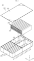
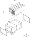
- FIG. 1 is an exploded, schematic perspective view showing a partial configuration of a battery pack according to an embodiment of the present disclosure.
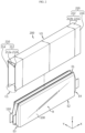
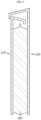
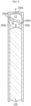
- FIG. 2 is an exploded perspective view schematically showing the configuration of a pouch-type battery cell and a cell cover accommodated inside a battery pack according to an embodiment of the present disclosure.
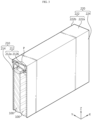
- FIG. 3 is a perspective view schematically showing the coupling configuration of a pouch-type battery cell and a cell cover accommodated inside a battery pack according to an embodiment of the present disclosure.
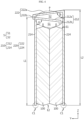
- FIG. 4 is a Y-Z cross-sectional view of FIG. 3 .
- a battery pack 10 includes a plurality of pouch-type battery cells 100, a pack case 300, and a cell cover 200.
- the pouch-type battery cell 100 may include an electrode assembly, an electrolyte, and a pouch exterior material.
- a plurality of such pouch-type battery cells 100 may be included in the battery pack 10. And, these plurality of pouch-type battery cells 100 may be stacked in at least one direction. For example, referring to what is shown in FIGS. 1 to 4 , the plurality of pouch-type battery cells 100 may be stacked and disposed in the horizontal direction, for example, in the left-right direction (Y-axis direction in the drawing). In addition, the plurality of pouch-type battery cells 100 may be disposed in the front-rear direction (X-axis direction in the drawing) as shown in FIG. 1 .
- the plurality of pouch-type battery cells 100 may be disposed in the horizontal direction, but may be disposed to form a plurality of rows in the left-right direction and in the horizontal direction.
- the plurality of pouch-type battery cells 100 may be stacked in a form where ten cells disposed in the left-right direction are provided in two rows in the front-rear direction.
- each pouch-type battery cell 100 may have a receiving portion indicated by 'R' and edge portions indicated by 'E1' to 'E4'.
- the receiving portion R may be a portion that accommodates an electrode assembly in which a positive electrode plate and a negative electrode plate are stacked on top of each other with a separator interposed therebetween.
- an electrolyte may be accommodated in this receiving portion R.
- the edge portions E1 to E4 may be disposed in a form surrounding the receiving portion R.
- the edge portions E1 to E4 may be sealing portions where the pouch exterior material, which is the case of the pouch-type battery cell 100, is sealed.
- the edge portions E1 to E4 may be sealing portions where the pouch exterior material, which is the case of the pouch-type battery cell 100, is sealed.
- there are four edge portions E1 to E4 which can be said to be located at the upper edge, lower edge, front edge, and rear edge, respectively, based on the receiving portion R.
- all four edge portions E1 to E4 may be sealing portions.
- some of the four edge portions E1 to E4 may be configured in a folded form that is not a sealing portion.
- the upper edge portion E1, the front edge portion E3, and the rear edge portion E4 are all sealing portions, but the lower edge portion E2 may be a folded portion of the pouch exterior material.
- the upper edge portion E1 may be a so-called double side folding DSF portion that is folded twice as a sealing portion of the pouch-type battery cell 100, and the lower edge portion E2 may be an unsealed portion of the pouch-type battery cell 100.
- the pack case 300 may have an empty space therein to accommodate a plurality of pouch-type battery cells 100.
- the pack case 300 may include an upper case 310 and a lower case 320, as shown in FIG. 1 .
- the lower case 320 may be configured in the form of a box with an open top to accommodate a plurality of battery cells in the internal space.
- the upper case 310 may be configured in the form of a cover that covers the top opening of the lower case 320.
- the upper case 310 may also be configured in the form of a box with an open bottom.
- the cell cover 200 together with a plurality of pouch-type battery cells 100 may be accommodated in the internal space of the pack case 300.
- the pack case 300 may be made of a plastic or metal material.
- the pack case 300 may employ various exterior materials of battery packs known at the time of filing the present disclosure.
- the pack case 300 places the edge portions E1 to E4 of the pouch-type battery cell 100 downward in the internal space so that the pouch-type battery cell 100 is accommodated in an upright state.
- the lower edge portion E2 of the pouch-type battery cell 100 is positioned downward is provided.
- the cell cover 200 may be configured to surround the pouch-type battery cell 100 in the internal space of the pack case 300. That is, the cell cover 200 may be configured to surround at least some of the pouch-type battery cells 100 among the plurality of pouch-type battery cells 100 included in the battery pack 10. Moreover, the cell cover 200 may be arranged to at least partially surround the pouch-type battery cell 100.
- the cell cover 200 may be configured to surround one or more pouch-type battery cells 100.
- one cell cover 200 is shown in a form surrounding two pouch-type battery cells 100.
- the cell cover 200 may be configured to surround two or more pouch-type battery cells 100 together.
- FIG. 5 is a cross-sectional view schematically showing the coupling configuration of a pouch-type battery cell and a cell cover accommodated inside a battery pack according to another embodiment of the present disclosure.
- one cell cover 200 is shown in a form surrounding one pouch-type battery cell 100.
- one cell cover 200 may be configured to surround only one pouch-type battery cell 100.
- the cell cover 200 is individually coupled to each pouch-type battery cell 100 among the plurality of pouch-type battery cells 100.
- a battery cell in which all four edge portions E1 to E4 are sealed may be referred to as a four-sided sealing cell, and a battery cell in which three edge portions E1, E3, E4 are sealed may be referred to as a three-sided sealing cell.
- the cell cover 200 may be configured to surround both sides of the receiving portion R and a portion of the edge portions E1 to E4 of the pouch-type battery cell 100, which may be a four-sided sealing cell or a three-sided sealing cell. For example, as shown in FIG.
- the cell cover 200 when one cell cover 200 is configured to surround one pouch-type battery cell 100, the cell cover 200 may be configured to surround both surfaces of the receiving portion R (e.g., the left surface and the right surface of the same receiving portion R) of the same pouch-type battery cell 100, and a part of the edge portion of the corresponding battery cell 100 from the outside.
- the cell cover 200 when one cell cover 200 is configured to surround a plurality of pouch-type battery cells 100, for example, a plurality of battery cells disposed in the left-right direction, it may be configured to surround the outer surface of the receiving portion of the outermost battery cell and one edge portion of the entire battery cell.
- one cell cover 200 may be configured to surround two pouch-type battery cells 100 stacked in the left-right direction, as shown in FIGS. 2 to 4 . At this time, the cell cover 200 may be configured to surround the left surface of the left battery cell, one edge portion of two battery cells, and the right surface of the right battery cell.
- the cell cover 200 may be configured to support a plurality of pouch-type battery cells 100 in an upright state. As shown in FIG. 2 , each pouch-type battery cell 100 has two wide surfaces on which the receiving portion R is located, and the edge portions E1 to E4, which are the edges of the wide surfaces, may have narrow surfaces where sealing portions or folded portions of the pouch exterior material are present. Therefore, it is generally difficult to stack the pouch-type battery cells 100 in a vertically upright form with the narrow surface facing down. However, in the battery pack according to the present disclosure, the cell cover 200 may be configured to surround one or more pouch-type battery cells 100 and support the wrapped pouch-type battery cells 100 in a standing state, that is, an upright state.
- the cell cover 200 may be configured such that a plurality of pouch-type battery cells 100 may be stacked in the horizontal direction in a vertically upright state.
- a plurality of cell covers 200 are stacked on each other in the horizontal direction, and each cell cover 200 may be configured to surround one or more pouch-type battery cells 100.
- the configuration in which the plurality of pouch-type battery cells 100 are stacked side by side in the horizontal direction in each upright state may be stably maintained by the cell cover 200.
- the cell cover 200 may be configured to be self-supporting in the internal space of the pack case 300. That is, the cell cover 200 may be configured to maintain an upright state on its own without the help of other components included in the battery pack, such as the pack case 300 or the pouch-type battery cell 100.
- the cell cover 200 may be configured to partially surround the pouch-type battery cell 100 so that at least one side of the wrapped pouch-type battery cell 100 is exposed to the outside. That is, the cell cover 200 may be configured to cover only a portion of the pouch-type battery cell 100 without fully surrounding the entire pouch-type battery cell 100. In particular, the cell cover 200 may be configured so that at least one side of the pouch-type battery cell 100 is exposed toward the pack case 300. In this respect, the cell cover 200 may be referred to by terms such as a cell sleeve.
- the cell cover 200 is configured to surround two pouch-type battery cells 100, but the wrapped pouch-type battery cells 100, that is, the lower edge portion E2 of the battery cell 100 accommodated in the internal space may not be surrounded by the cell cover 200. Therefore, the lower edge portion E2 of the battery cell 100 may be exposed toward the pack case 300 and may directly face the pack case 300. In particular, referring to the embodiment of FIG. 1 , the lower edge portion E2 of the battery cell 100 may be exposed toward the bottom surface of the lower case 320.
- the pouch-type battery cell 100 and the cell cover 200 may be directly seated on the pack case 300.
- the lower ends of the pouch-type battery cell 100 and the cell cover 200 may be seated on the upper surface of the bottom of the pack case 300.
- the cell cover 200 may be directly seated on the bottom surface of the lower case 320 in the embodiment of FIG. 1 .
- a portion of the cell cover 200 such as a lower end portion of the cell cover 200 indicated by 'C1' in FIG. 2 may be seated in direct contact with the bottom surface of the lower case 320.
- the cell cover 200 may be configured to remain stably seated.
- the cell cover 200 is made of a metal material with excellent rigidity such as steel, especially stainless steel (SUS), the self-supporting state may be maintained more stably. Therefore, in this case, the standing state of the pouch-type battery cell 100 may be more reliably supported.
- SUS stainless steel
- the cell cover 200 may be configured to support the battery cell 100 accommodated therein.
- the cell cover 200 may be configured to stably support the upright state of the battery cell 100 accommodated therein.
- the cell cover 200 may be configured to support the stacked state of the plurality of pouch-type battery cells 100 inside the pack case 300 through a structure that surrounds the battery cells in this way.
- a plurality of pouch-type battery cells 100 may be stacked in the horizontal direction (Y-axis direction in the drawing) as shown in FIGS. 1 to 4 .
- the cell cover 200 may be configured to stably maintain the stacked state of the plurality of pouch-type battery cells 100 stacked in the horizontal direction.
- a plurality of pouch-type battery cells 100 may be directly seated and accommodated inside the pack case 300 without a module case.
- the exterior material is made of a soft material, so it can be said that it is vulnerable to external impact and has low hardness. Therefore, it is not easy to accommodate the pouch-type battery cell 100 itself inside the pack case 300 without accommodating it in the module case.
- the plurality of pouch-type battery cells 100 are coupled to the cell cover 200 in a state where at least a portion is surrounded by the cell cover 200 and then are directly accommodated inside the pack case 300, and their stacking state may be maintained stably.
- a CTP-type battery pack using the pouch-type battery cell 100 may be implemented more efficiently. That is, in the case of the present disclosure, the battery pack 10 may be arranged in a form of directly accommodating the pouch-type battery cell 100 inside the pack case 300, rather than accommodating the pouch-type battery cell 100 inside a separate module case and accommodating this module case inside the pack case 300. In this case, at least one side of the pouch-type battery cell 100 may be exposed to the outside of the cell cover 200 and may be disposed to directly face the pack case 300.
- the battery pack 10 does not need to be further provided with a module case, a stacking frame, or fastening members such as bolts for maintaining the stacked state of the cells. Accordingly, the space occupied by other components, such as a module case or a stacking frame, or the resulting space for securing tolerances may be eliminated. Therefore, since the battery cell 100 may occupy more space as much as the removed space, the energy density of the battery pack 10 may be further improved.
- the volume and weight of the battery pack 10 may be reduced, and the manufacturing process may be simplified.
- the assemblability of the battery pack 10 may be improved.
- the process of preparing a battery module by accommodating the pouch-type battery cell 100 in a module case, and the process of accommodating one or more battery modules prepared in this way in the pack case 300 may not be performed.
- the manufacturing process may be simplified, and manufacturing time may be reduced.
- handling of the pouch-type battery cell 100 may become easier.
- the pouch-type battery cells 100 may be held by a jig or the like.
- the jig may hold the cell cover 200 surrounding the pouch-type battery cell 100, rather than directly holding the pouch-type battery cell 100. Accordingly, damage to or breakage of the pouch-type battery cell 100 caused by the jig may be prevented.
- the cell cover 200 is coupled to the pouch-type battery cell 100, so that the pouch-type battery cell 100 may be effectively protected without a module case.
- the cooling performance of the battery pack 10 may be secured more effectively.
- the pouch-type battery cell 100 and the pack case 300 may be in direct contact with each other through the open end of the cell cover 200. That is, one side of the pouch-type battery cell 100 disposed adjacent to the open end of the cell cover 200 may directly face or contact the pack case 300. Therefore, the heat emitted from each pouch-type battery cell 100 is directly transferred to the pack case 300, so that cooling performance may be improved.
- efficient cooling performance may be implemented. And, in this case, there may be no space for a cooling medium such as air to flow in between the pouch-type battery cells 100.
- the cell cover 200 is open, which may be advantageous in reducing the weight of the battery pack 10.
- the cell cover 200 is made of a material such as steel, if the lower end portion of the cell cover 200 is formed in an open shape, the weight of the cell cover 200 may be reduced by as much as the lower plate.
- the battery pack 10 may include many cell covers 200, and if all the cell covers 200 do not have a lower plate and are formed in an open shape, the weight of the battery pack 10 may be significantly reduced.
- the configuration of a long cell having a long length in a specific direction may be prepared more easily.
- the process of inserting the electrode assembly into a prismatic case may not be easy.
- there may be a problem such as damage to the electrode assembly during the insertion process of the electrode assembly.
- unidirectional lengthening of the pouch-type battery cell 100 and the cell cover 200 may be easily implemented during the steps of molding the pouch exterior material, manufacturing the electrode assembly, or manufacturing the cell cover 200.
- the process of inserting the long cell manufactured to be lengthened in one direction in this way through an open side (e.g., bottom) of the cell cover 200 may be easily performed. Therefore, according to this aspect of the present disclosure, even when manufacturing the battery pack 10 using long cells, it is possible to secure excellent assemblability, processability, productivity, and the like.
- the configuration of supporting and protecting one or more pouch-type battery cells 100 by one cell cover 200 may be easily implemented.
- the process of handling one or more pouch-type battery cells 100 through the cell cover 200 may be performed easily and safely.
- one cell cover 200 may face the surfaces of the two receiving portions R with respect to the pouch-type battery cell 100 accommodated therein. Therefore, cooling performance between the receiving portion R and the cell cover 200 may be further improved. In particular, in this case, surface cooling is implemented through a wide surface of the receiving portion R, and thus cooling efficiency may be improved.
- the cell cover 200 may be configured to surround an edge portion that is not provided with an electrode lead among several edge portions of the pouch-type battery cell 100 accommodated therein.
- the pouch-type battery cell 100 may have two electrode leads 110, that is, a positive electrode lead and a negative electrode lead.
- the two electrode leads may be located at the front edge portion E3 and the rear edge portion E4, respectively.
- the cell cover 200 may be configured to surround one of the two remaining edge portions E1, E2 except for the front edge portion E3 and the rear edge portion E4.
- the cell cover 200 may surround the upper edge portion E1 of the pouch-type battery cell 100 and expose the lower edge portion E2.
- the cell cover 200 may be arranged to cover both sides of the receiving portion R and the upper edge portion E1 with respect to one or more pouch-type battery cells 100 accommodated and wrapped therein.
- the cell cover 200 may be configured to surround all of the left surface and right surface of the receiving portion R, and the upper edge portion E1 for one pouch-type battery cell 100.
- the cell cover 200 may be configured to surround the left surface of the receiving portion of the left battery cell, the upper edge portions E1 of the two battery cells, and the right surface of the receiving portion of the right battery cell.
- the configuration of supporting and protecting one or more battery cells by one cell cover 200 may be easily implemented.
- the lower edge portion E2 may be located adjacent to the open end of the cell cover 200 to face the pack case 300 without being surrounded by the cell cover 200, and may be in direct face-to-face contact with the pack case 300. Therefore, heat from the pouch-type battery cell 100 wrapped by the cell cover 200 may be quickly and smoothly discharged toward the pack case 300 below. Accordingly, the cooling performance of the battery pack 10 may be secured more effectively.
- this configuration may be implemented more effectively when cooling is mainly performed in the lower portion of the pack case 300.
- cooling may be mainly performed in the lower portion of the pack case 300 as it is mounted on the lower portion of the vehicle body.
- the lower edge portion E2 of each pouch-type battery cell 100 is in face-to-face contact with the pack case 300, heat is quickly transferred from each battery cell 100 to the pack case 300, and thus cooling performance may be further improved.
- the upper edge portion E1 which is a sealing portion
- the lower edge portion E2 which is an unsealed portion
- the upper edge portion E1, which is a sealing portion may be surrounded by the cell cover 200 and disposed to face the cell cover 200, thereby being more advantageous for directional venting.
- the cell cover 200 may be made of various materials to ensure rigidity.
- the cell cover 200 may be made of a metal material.
- the stacked state of the pouch-type battery cells 100 may be more stably maintained, and the pouch-type battery cells 100 may be more safely protected from external impact.
- the cell cover 200 may include a steel material, more particularly a SUS material.
- the cell cover 200 may be entirely made of SUS material.
- the cell cover 200 made of SUS may have a thickness of approximately 0.2 mm.
- the cell cover 200 when the cell cover 200 is made of a steel material, it has excellent mechanical strength and rigidity, and thus may more stably support the stacked state of the pouch-type battery cells 100. In addition, in this case, it is possible to more effectively prevent damage to or breakage of the pouch-type battery cell 100 from external impacts, such as needle bodies. In addition, in this case, handling of the pouch-type battery cell 100 may become easier.
- the overall structure may be stably maintained due to its high melting point in the event of occurrence of a flame from the battery cell 100.
- the steel material since the steel material has a higher melting point than aluminum material, it may not be melted even with flame ejected from the battery cell 100 and its shape may remain stable. Therefore, the effect of preventing or delaying flame propagation between the battery cells 100, venting control effects, and the like may be secured excellently.
- the cell cover 200 may include an insulating coating layer on its inner surface.
- the insulating coating layer may be coated, applied, or attached with any one of silicone resin, polyamide, and rubber. According to the configuration of the insulating coating layer of the cell cover 200 according to this embodiment, the insulating coating effect may be maximized with a minimum amount of coating.
- insulation between the pouch-type battery cell 100 and the cell cover 200 may be strengthened.
- the cell cover 200 may be at least partially adhered to the outer surface of the battery cell 100.
- the cell cover 200 may have its inner surface adhered to the receiving portion R of the pouch-type battery cell 100.
- the member for adhesion may be thermally conductive. Through this adhesion, the cell cover 200 is firmly coupled to the battery cell 100 and may help discharge heat generated in the battery cell 100 to the outside of the battery cell 100.
- One or more cell covers 200 may be included in the battery pack 10.
- the plurality of cell covers 200 may be spaced apart from each other.
- the plurality of cell covers 200 may be spaced apart in the X-axis direction. Direct heat transfer between the cell covers 200 may be blocked through the spaced apart space.
- separate members required to configure the battery pack 10 may be inserted through the spaced apart space.
- an insulating pad or a flame suppression pad may also be interposed in at least a portion between the plurality of cell covers 200. Such an insulating pad or a flame suppression pad may prevent heat or flame that may be generated within any one cell cover 200 from being transferred to another cell cover 200 and affecting the other battery cells 100.
- the flame suppression pad may be formed of a heat-resistant resin such as vinyl chloride resin, a material such as silicon or ceramic, a composite of a heat-resistant resin and a ceramic or glass filler, or a metal plate coated with insulation, but this is exemplary and any flame-retardant material is sufficient. It is preferable that the flame suppression pad is made of a material that does not decompose, melt, or ignite at least up to the temperature at which thermal runaway of the battery cell 100 is generated (e.g., 150°C to 200°C). For example, when the thickness of the cell cover 200 is about 0.2 mm, the insulation pad or flame suppression pad may have a thickness of about 2 mm. In other words, the plurality of cell covers 200 may also be spaced apart from each other by about 2 mm.
- a heat-resistant resin such as vinyl chloride resin, a material such as silicon or ceramic, a composite of a heat-resistant resin and a ceramic or glass filler, or a metal plate coated with insulation, but this is exemplary and
- an adhesive member may be interposed between the cell covers 200.
- an adhesive member may be interposed in a portion where the two cell covers 200 face each other to adhesively fix them.
- the connection configuration between multiple cell covers 200 may be made more robust.
- the adhesive member may be insulating. This adhesive member may achieve insulation between the cell covers 200, which may be made of a metal material.
- the cell cover 200 may be configured to group and unitize a plurality of pouch-type battery cells 100 included in the battery pack.
- one cell cover 200 can be said to constitute one cell unit.
- the one cell unit may include one or a plurality of pouch-type battery cells 100.
- the battery pack 10 may include a plurality of cell units, in which case, the cell cover 200 can be said to be included in plurality in the battery pack.
- the battery pack may include the same number of cell covers 200 as the number of pouch-type battery cells 100.
- the battery pack may include a smaller number of cell covers 200 than the number of pouch-type battery cells 100.
- each cell group surrounded by the cell cover 200 may be referred to as a cell bank unit in addition to a cell unit.
- the pouch-type battery cells 100 in the cell unit or cell bank may include an electrical connection in series and/or in parallel through a busbar or the like.
- the cell cover 200 is a unit cover and may include a first cover 210 and a second cover 220, as shown in FIGS. 2 to 5 .
- the cell cover 200 has a separation space S between the cell cover 200 and the upper edge portion E1 of the wrapped pouch-type battery cell 100.
- the cell cover 200 has a pocket structure P so that the gas emitted from the pouch-type battery cell 100 is restricted from moving in the horizontal direction and upward across the upper edge portion E1 within the separation space S.
- the pouch-type battery cell 100 has the advantage of enabling to implement a secondary battery of the same capacity with a smaller volume and mass on account of its being lightweight, less prone to electrolyte leakage, and flexible in shape, it has a task of ensuring safety due to a risk of explosion in case of overheating, which is one of the important tasks.
- Overheating of the pouch-type battery cell 100 occurs due to various reasons, one of which may be a case where an overcharge exceeding a limit flows through the pouch-type battery cell 100.
- the pouch-type battery cell 100 When an overcharge is applied, the pouch-type battery cell 100 generates heat by Joule heat, and thus the internal temperature of the battery cell 100 rapidly increases. A rapid rise in temperature may cause a decomposition reaction of the electrolyte to generate gas.
- the cell cover 200 included in the battery pack 10 may be configured such that the gas emitted from the pouch-type battery cell 100 into the separation space S between the two unit covers 210, 220 may be collected once and discharged in a guided direction, thereby ensuring the safety of the secondary battery.
- the first cover 210 may be configured to surround the left surface and one edge of the wrapped pouch-type battery cell 100.
- the second cover 220 may be configured to surround the right surface and the other edge of the wrapped pouch-type battery cell 100.
- the first cover 210 and the second cover 220 are each configured in an approximate L shape, so that the cell cover 200 according to this embodiment of the present disclosure can be said to be configured in a form where two L-shaped unit covers 210, 220 are coupled to each other.
- first cover 210 and the second cover 220 may be configured to surround the upper edge of the pouch-type battery cell 100.
- These two unit covers 210, 220 may be fastened and fixed to each other by various fastening methods such as welding, adhesion, fitting, and hooking.
- the cell cover 200 may be configured to surround both sides and upper edges of at least some of the pouch-type battery cells 100.
- the cell cover 200 composed of two unit covers 210, 220 can be said to include two side cover portions surrounding both left and right sides of the pouch-type battery cell 100 accommodated therein and an upper cover portion surrounding the upper edge thereof, as shown in FIGS. 2 to 5 .
- the upper cover portion is at least partially formed of two layers.
- the configuration of the upper cover portion may be modified to form a multilayer of two or more layers. It can be said that the upper cover portion is configured to surround the top of the upper edge portion E1 of the pouch-type battery cell 100.
- the side cover portion can be said to extend downward from one end of the upper cover portion and surround the outside of one side receiving portion R of the pouch-type battery cell 100.
- the cell cover 200 is provided with the pocket structure P, the movement of the gas emitted from the pouch-type battery cell 100 in some directions is restricted. As the gas is ejected, active material particles inside the pouch-type battery cell 100 may be discharged to the outside while being heated to a high temperature, and these high-temperature particles may appear in the form of sparks. According to the present disclosure, the pocket structure P of the cell cover 200 may capture such particles, thereby having an excellent spark blocking effect.
- the upper cover portion is formed in two layers. In this embodiment, it can be said that there are two pocket structures P. In a configuration where the upper cover portion is formed in two layers as in the embodiment, spark-shaped particles may be captured in each layer.
- the two unit covers 210, 220 may be configured with one end bent toward each other.
- the upper end of the first cover 210 may be bent in the right direction
- the upper end of the second cover 220 may be bent in the left direction.
- the upper end of the first cover 210 and the upper end of the second cover 220 may be overlapped in the vertical direction while being at least partially spaced apart from each other. That is, the upper end of the first cover 210 and the upper end of the second cover 220 may together constitute the upper cover portion of the cell cover 200, so that the upper cover portion in a multi-layer form may be provided. More specifically, referring to the configuration of FIG.
- the upper end of the first unit cover 210 constitutes a first layer of the upper cover portion
- the upper end of the second unit cover 220 constitutes a second layer of the upper cover portion.
- sparks (particles) inside the cell cover 200 may be captured on the first layer by the first unit cover 210 and/or on the second layer by the second unit cover 220.
- Each of the two unit covers 210, 220 may be configured in a form of bending one plate.
- each of the two unit covers 210, 220 may be configured to surround one or more pouch-type battery cells 100 by bending one end with respect to one plate.
- the cross-sectional configuration of the cell cover 200 can be said to be roughly similar to an 'n' shape. Therefore, in this case, the cell cover 200 may also be referred to as 'n-fin'.
- the respective cross-sectional configuration of the first cover 210 and the second cover 220 can be said to be roughly similar to an 'L' shape. Therefore, in this case, the first cover 210 and the second cover 220 may also be referred to as 'L-fin'.
- the cell cover 200 can be said to be an n-fin formed of two L-fins.
- the first cover 210 includes a first upper cover portion 212 configured to surround the top of the upper edge portion E1 of the pouch-type battery cell 100, and a first side cover portion 214 extending downward from one end of the first upper cover portion 212 and surrounding the outside of one side receiving portion R of the wrapped pouch-type battery cell 100.
- the second cover 220 includes a second upper cover portion 222 configured to surround the top of the upper edge portion E1 of the pouch-type battery cell 100, and a second side cover portion 224 extending downward from one end of the second upper cover portion 222 and surrounding the outside of the other side receiving portion R of the wrapped pouch-type battery cell 100.
- the first upper cover portion 212 and the second upper cover portion 222 are spaced apart from each other in the vertical direction. In this embodiment, the second upper cover portion 222 is spaced apart upward from the first upper cover portion 212.
- the first side cover portion 214 may be configured to extend downward from one end of the first upper cover portion 212.
- the first side cover portion 214 may be configured to extend long in a downward direction (-Z-axis direction in the drawing) from the left end of the first upper cover portion 212.
- the first side cover portion 214 may be formed in a planar shape. In this case, the first side cover portion 214 may be configured in a bent form at the first upper cover portion 212.
- the first side cover portion 214 may be configured to surround the outside of one side receiving portion R of the pouch-type battery cell 100 accommodated therein.
- the first side cover portion 214 may be configured to surround the left surface of the receiving portion R of the accommodated pouch-type battery cell 100.
- the first side cover portion 214 may be in direct contact with the outer surface of the receiving portion R.
- the second side cover portion 224 may be positioned to be spaced apart from the first side cover portion 214 in the horizontal direction. And, the second side cover portion 224 may be configured to extend downward from one end of the second upper cover portion 222. For example, the second side cover portion 224 may be configured to extend long downward from the right end of the second upper cover portion 222. Moreover, the second side cover portion 224 may also be configured in a planar shape like the first side cover portion 214. In this case, it can be said that the second side cover portion 224 and the first side cover portion 214 are disposed parallel to each other while being spaced apart in the horizontal direction. And, the second side cover portion 224 may be configured in a bent form at the second upper cover portion 222.
- the first side cover portion 214 and the first upper cover portion 212 may be formed of one plate.
- the second side cover portion 224 and the second upper cover portion 222 may also be formed of one plate.
- each component may be distinguished by a bent portion.
- one bent portion may be formed in one plate.
- the first side cover portion 214 and the first upper cover portion 212 may be distinguished, and the second side cover portion 224 and the second upper cover portion 222 may be distinguished.
- the configuration of forming a bent portion in one plate to form the cell cover 200 may be implemented in various ways, such as pressing or roll forming.
- manufacturing of the cell cover 200 may be simplified. Therefore, the manufacturing cost or time of the battery pack may be reduced.
- the mechanical strength and rigidity of the cell cover 200 may be secured at a higher level.
- heat conduction performance through the cell cover 200 is further enhanced, which may further improve cooling performance.
- the second side cover portion 224 may be configured to surround the outside of the other side receiving portion R of the pouch-type battery cell 100 accommodated therein.
- the second side cover portion 224 may be configured to surround the right surface of the receiving portion R of the accommodated pouch-type battery cell 100 at the right side.
- the second side cover portion 224 may be in direct contact with the outer surface of the receiving portion R.
- the internal space may be limited by the first and second upper cover portions 212, 222 and the first and second side cover portions 214, 224.
- the cell cover 200 may accommodate one or more pouch-type battery cells 100 in this limited internal space.
- first upper cover portion 212 and the second upper cover portion 222 may be configured to surround the top of the upper edge portion E1 of the pouch-type battery cell 100 accommodated therein.
- the separation space S inside the cell cover 200 may be configured to be empty.
- a path through which venting gas or the like moves may be provided due to the empty space formed between the side portion (edge portion) of the pouch-type battery cell 100 and the cell cover 200.
- venting gas when venting gas is generated in the battery cell 100 accommodated inside the cell cover 200 due to thermal runaway or the like, the generated venting gas may move in the front-rear direction (X-axis direction) through the empty space between the upper edge portion E1 adjacent to the first upper cover portion 212, the first upper cover portion 212, and the first side cover portion 214. Accordingly, even if a configuration for discharging venting gas to the outside of the cell cover 200, such as a through hole or incision to be described later, is located in any part of the cell cover 200 or other components, the venting gas may move smoothly and quickly to the part where the corresponding venting configuration is located. Therefore, the internal pressure of the cell cover 200 may be prevented from increasing, and efficient venting control, such as guiding the discharge direction of the venting gas, may be possible.
- the pocket structure P divides the separation space S into two or more spaces S1, S2 communicating with each other.
- the movement of venting gas between the divided spaces S1, S2 may be restricted. There in an effect of trapping high-temperature particles in each of the divided spaces S1, S2.
- the second upper cover portion 222 covers the first upper cover portion 212 and extends to the first side cover portion 214. Through this structure, the upper edge portion E1 of the pouch-type battery cell 100 is surrounded by the cell cover 200.
- the first upper cover portion 212 may have a first portion 212a covering the pouch-type battery cell 100, and a second portion 212b having a surface direction different from that of the first portion 212a. That is, the first upper cover portion 212 may be configured in three dimensions rather than in a planar shape. In this case, the first portion 212a of the first upper cover portion 212 may surround the upper edge portion E1 of the pouch-type battery cell 100. In addition, the first portion 212a of the first upper cover portion 212 may be inclined downward. For example, the first portion 212a may be configured to be bent downward from the first side cover portion 214 so that the right end of the first portion 212a is inclined downward.
- the effect of capturing sparks (particles) may be further improved due to the inclined configuration. That is, the inclined configuration of the first portion 212a has the effect of making the area of the part corresponding to the exit when leaving the space S 1 smaller than the area of the part corresponding to the entrance when entering the space S 1 from the perspective of the particle. Therefore, once a particle is trapped in the space S1, it becomes difficult to escape from the space S 1.
- the second portion 212b of the first upper cover portion 212 is connected to the end of the first portion 212a and may be bent downward to form a blocking portion. By such a blocking portion, the spark blocking effect may be further improved.
- the first portion 212a of the first upper cover portion 212 may extend to a length adjacent to the second side cover portion 224. It may be preferable to have the first portion 212a as long as possible to lengthen the part covering the pouch-type battery cell 100 inside.
- the angle ⁇ formed by the first side cover portion 214 and the first portion 212a of the first upper cover portion 212 may be an acute angle.
- the space S1 surrounded by the first side cover portion 214 and the first upper cover portion 212 is highest at the part where the first side cover portion 214 and the first upper cover portion 212 meet, that is, at the bent portion (corner) of the first cover 210.
- the space S1 may be an upwardly concave space having a height peak at the bent portion of the first cover 210. Accordingly, the venting gas with an upward movement is easy to collect within the concave space, thereby having an excellent particle capture effect.
- the angle formed by the first portion 212a and the second portion 212b of the first upper cover portion 212 may also be an acute angle.
- the place where the first portion 212a and the second portion 212b meet becomes a corner, and it is easy for venting gas to collect in that part due to the structural feature of the corner. Therefore, the particle capture effect is excellent.
- the second upper cover portion 222 may have a first portion 222a covering the pouch-type battery cell 100, and a second portion 222b having a surface direction different from that of the first portion 222a. That is, the second upper cover portion 222 may be configured in three dimensions rather than in a planar shape. In this case, the first portion 222a of the second upper cover portion 222 is spaced apart upward from the first portion 212a of the first upper cover portion 212 surrounding the upper edge portion E1 of the pouch-type battery cell 100. In addition, the first portion 222a of the second upper cover portion 222 may be inclined downward. For example, the first portion 222a may be configured to be bent downward from the second side cover portion 224 so that the left end of the first portion 222a is inclined downward.
- the effect of capturing high-temperature particles may be further improved due to the inclined configuration.
- the inclined configuration of the first portion 222a has the effect of making the area of the part corresponding to the exit when leaving the space S2 smaller than the area of the part corresponding to the entrance when entering the space S2 from the perspective of the particle. Therefore, once a particle is trapped in the space S2, it becomes difficult to escape from the space S2.
- the second portion 222b of the second upper cover portion 222 is connected to the end of the first portion 222a and may be bent downward to form a blocking portion. By such a blocking portion, the spark blocking effect may be further improved.
- the first portion 222a of the second upper cover portion 222 may extend to a length adjacent to the first side cover portion 214. It may be preferable to have the first portion 222a as long as possible to lengthen the part overlapping the first portion 212a of the first upper cover portion 212.
- the angle ⁇ formed by the second side cover portion 224 and the first portion 222a of the second upper cover portion 222 may be an acute angle.
- the space S2 surrounded by the second side cover portion 224 and the second upper cover portion 222 is highest at the part where the second side cover portion 224 and the second upper cover portion 222 meet, that is, at the bent portion (corner) of the second cover 220.
- the space S2 may be an upwardly concave space having a height peak at the bent portion of the second cover 220. Accordingly, the venting gas with an upward movement is easy to collect within the concave space. Therefore, the particle capture effect is excellent.
- the space S1 may be an upwardly concave space having a height peak at the bent portion of the first cover 210
- the space S2 may be an upwardly concave space having a height peak at the bent portion of the second cover 220.
- the upwardly concave spaces S1, S2 have the effect of being placed to cross each other on the left and right sides, and on the lower and upper sides, respectively, within the cell cover 200. That is, through the special structure of the cell cover 200, the space S within the cell cover 200 is divided into two spaces S1, S2 crossing each other, thereby maximizing the gas capture effect in each space.
- the second portion 222b of the second upper cover portion 222 may cover the first side cover portion 214. More specifically, the second portion 222b corresponding to the left end at the upper end of the second cover 220, which is located relatively upward, is bent downward, and may be configured to be in close contact with the outer surface of the first cover 210, particularly the outer surface of the first side cover portion 214. This configuration makes the coupling between the first side cover portion 214 and the second side cover portion 224 tighter and may prevent venting gas from leaking from the cell cover 200 toward the first side cover portion 214 or the second side cover portion 224.
- the second side cover portion 224 may have a longer length in the vertical direction compared to the first side cover portion 214.
- the length of the first side cover portion 214 is indicated by L1 and the length of the second side cover portion 224 is indicated by L2. In this case, it may be L2 > L1.
- the lower ends C1 of the first side cover portion 214 and the second side cover portion 224 may contact the bottom surface of the pack case 300. If the heights of the lower ends C1 of the first side cover portion 214 and the second side cover portion 224 are the same, a separation configuration between the first upper cover portion 212 connected to the first side cover portion 214 and the second upper cover portion 222 connected to the second side cover portion 224 may be achieved just by making the length L2 of the second side cover portion 224 longer than the length L1 of the first side cover portion 214.
- the space S 1 formed by the first side cover portion 214, the first upper cover portion 212, and the upper edge portion E1 of the pouch-type battery cell 100 is divided from the space S2 formed by the second side cover portion 224, the second upper cover portion 222, and the upper edge portion E1 of the pouch-type battery cell 100, but in communication with each other.
- the movement of the venting gas in the horizontal direction and upward across the upper edge portion E1 within the separation space S is limited by the pocket structure P, so that the movement of the venting gas between the divided spaces S1, S2 may be restricted. Accordingly, a spark blocking effect may be exhibited.
- the vertical lengths of the first and second side cover portions 214, 224, the angles at which the first portions 212a, 222a are inclined, the lengths of the first portions 212a, 222a, and the like may be determined so that the divided spaces S1, S2 may have roughly similar volumes. This is to prevent the venting gas from being unilaterally concentrated in either space or particles from being captured.
- the gas emitted from the pouch-type battery cell 100 may move upward within the cell cover 200 in a relatively free space and may once be collected in the space S1 formed by the first side cover portion 214, the first upper cover portion 212, and the upper edge portion E1 of the pouch-type battery cell 100.
- the movement of the venting gas further upward is primarily restricted by the first portion 212a of the first upper cover portion 212.
- the movement of the venting gas in the horizontal direction is primarily restricted by the second portion 212b of the first upper cover portion 212.
- venting gas that escapes between the second portion 212b of the first upper cover portion 212 and the upper edge portion E1 of the pouch-type battery cell 100 and moves further upward may be collected again in the space S2 formed by the second side cover portion 224, the second upper cover portion 222, and the upper edge portion E1 of the pouch-type battery cell 100.
- the movement of the venting gas further upward is secondarily restricted by the first portion 222a of the second upper cover portion 222.
- the movement of the venting gas in the horizontal direction is secondarily restricted by the second portion 222b of the second upper cover portion 222.
- the cell cover 200 has an n-fin shape and may be configured in a closed form on the top side and the left and right sides based on the pouch-type battery cell 100 accommodated therein.
- the cell cover 200 may be configured such that the venting gas present therein is discharged downward.
- the pack case 300 may include a discharge hole 330 for discharging venting gas at the bottom.
- the discharge hole 330 of the pack case 300 may be configured to communicate with the internal space of the cell cover 200. That is, the cell cover 200 and the pouch-type battery cell 100 are seated on the bottom of the pack case 300, but the venting gas emitted from the pouch-type battery cell 100 is blocked from being discharged upward and in the lateral direction by the cell cover 200, and may only be discharged downward through the discharge hole 330 of the pack case 300 as indicated by the arrow.
- the venting gas may be discharged in one direction through two unit covers 210, 220.
- the discharged gas or flame may not be heading toward the upper side.
- a passenger is located on the upper side of the battery pack 10, such as in an electric vehicle, it is possible to suppress or delay gas or flame from heading toward the passenger according to the above embodiment.
- the safety of users located on the upper side, such as passengers, may be improved by allowing directional venting to be performed downward.
- directional venting may be achieved through the cell cover 200 and the pack case 300.
- the spark emission suppression effect may be achieved together with directional venting by the cell cover 200.
- the pocket structure P may suppress or delay the discharge of flames or sparks with strong straightness and contribute to lowering the temperature of the venting gas while the venting gas is discharged along a longer movement path.
- flame or gas may be guided and discharged in a preset direction.
- the flame or gas generated in the battery cell 100 may be discharged only in the preset direction through the cell cover 200. If the preset direction is not toward other cell covers 200, flame or gas may not be propagated to other battery cells 100 disposed adjacent to the battery cell 100 in which thermal runaway occurs. That is, even if thermal runaway occurs in any one battery cell 100, the effect of the thermal runaway on the other battery cells 100 may be minimized.
- the venting gas may be discharged downward, the effect of preventing the thermal runaway from being transferred to other battery cells is remarkable.
- a pocket structure P in which sparks or active material particles contained in the venting gas may be captured while dividing the separation space S through the inclined and bending configuration of the first upper cover portion 212 and the second upper cover portion 222 of the cell cover 200 is implemented, but any modifications of implementing this pocket structure by changing other shapes of the cell cover 200 are possible within the scope of the present disclosure.
- the pocket structure P While the pocket structure P maintains the function of guiding gas and flames generated in the event of ignition of the pouch-type battery cell 100 downward, it may suppress the movement to another adjacent pouch-type battery cell 100 even if high-temperature active material is ejected from any one pouch-type battery cell 100 where an explosion occurred. Accordingly, the venting gas is discharged, but the discharge of ignition sources such as sparks is suppressed. Therefore, the present disclosure may prevent a chain reaction such as a thermal runaway, fire or explosion propagating to other pouch-type battery cells 100, thereby greatly improving safety.
- the pocket structure P may be appropriately implemented in the separation space S within the cell cover 200 by changing the structure of the cell cover 200, which may be in a thin plate shape, and may suppress an increase in the size of the cell unit U1.
- an increase in weight may also be suppressed.
- the increase in size and weight of the battery pack 10 is suppressed, and safety is improved by preventing flames being ejected to the outside even in the event of flames erupting from the secondary battery.
- external discharge of sparks, flames, and high-temperature active material particles contained in the venting gas may be suppressed.
- spark blocking and the like may be implemented.
- the pack case 300 is made of aluminum for light weight, if sparks fly directly into the pack case 300, they may melt the pack case 300 and cause structural collapse. According to an embodiment of the present disclosure, sparks may be prevented from flying directly toward the pack case 300, so that such structural collapse may be prevented.
- the first side cover portion 214 and the pouch-type battery cell 100 may be bonded, and the second side cover portion 224 and the pouch-type battery cell 100 may be bonded. While the bonding between the first side cover portion 214 and the pouch-type battery cell 100 and between the second side cover portion 224 and the pouch-type battery cell 100 may be direct, it is preferable that indirect bonding is performed in a state of further including an insulating member 230 as what is shown in FIG. 6 .
- FIG. 6 is a cross-sectional view schematically showing the coupling configuration of a pouch-type battery cell and a cell cover accommodated inside a battery pack according to still another embodiment of the present disclosure.
- the cell cover 200 may further include an insulating member 230.
- the insulating member 230 may be made of an electrically insulating material and may be provided on the inner surface of the cell cover 200 in which the pouch-type battery cell 100 is accommodated.
- the insulating member 230 may have an adhesive layer on at least one side to be adhered to the inner surface of the cell cover 200.
- the insulating member 230 has adhesive layers on both sides, so that it may be adhered not only to the inner surface of the cell cover 200 but also to the pouch-type battery cell 100.
- the insulating member 230 may be made of a material having heat resistance.
- the insulating member 230 may be configured in the form of a heat-resistant tape in which an adhesive is applied to the surface of a ceramic sheet having heat resistance.
- the insulating member 230 may also be a film made of polyimide (PI).
- the thickness of the insulating member 230 may be approximately 0.05 mm.
- the insulating member 230 may also be located on the inner surface and the outer surface of the cell cover 200, that is, on both sides.
- a thermal interface material may be interposed to increase heat transfer performance between different components.
- TIM may be filled between the battery cell 100 and the cell cover 200, between the cell cover 200 and the pack case 300, and/or between the battery cell 100 and the pack case 300.
- the cooling performance of the battery pack may be further improved.
- the TIM is intended to reduce contact thermal resistance between members. In the battery pack where cooling is important, it is necessary to improve the thermal performance of the entire system by using a material capable of minimizing contact thermal resistance as described above.
- the TIM may be diverse, such as a thermally conductive grease, a thermal sheet, a thermal pad, a thermally conductive adhesive, and a phase change material (PCM).
- PCM phase change material
- the TIM may be any one of a thermally conductive silicone-based bond, a thermally conductive silicone pad, and a thermally conductive acrylic bond.
- Heat-dissipating silicone-based adhesives and heat-dissipating acrylic adhesives are commercially available in one or two liquid types and may be applied between different components by means of coating or injection.
- the heat-dissipating silicone pad includes a base film such as double-sided tape and release paper on the top and bottom of it, which may be applied between different components by an adhesive method after removing the release paper.
- heat-dissipating silicone-based adhesives, heat-dissipating silicone pads, and heat-dissipating acrylic adhesives have higher thermal conductivity compared to general adhesives, the amount and speed of heat transfer between different components may be further increased. Therefore, according to this embodiment of the present disclosure, the heat dissipation performance of the pouch-type battery cell 100 may be further enhanced, so that the cooling performance of the battery pack 10 may be further improved.
- the present disclosure it is possible to effectively respond to the thermal event in the event of a thermal runaway in a specific battery cell.
- emission control of venting gas and directional venting through the cell cover 200 may be implemented.
- internal short circuit or structural collapse may be prevented even when a thermal event occurs.
- the battery pack 10 may further include a control module 400 accommodated in the internal space of the pack case 300.
- This control module 400 may include a BMS.
- the control module 400 is mounted in the internal space of the pack case 300 and may be configured to generally control the charge/discharge operation and data transmission/reception operation of the pouch-type battery cell 100.
- the control module 400 may be provided in a pack unit rather than a module unit. More specifically, the control module 400 may be provided to control the charge/discharge state, power state, and performance state of the pouch-type battery cell 100 through pack voltage and pack current.
- the control module 400 estimates the state of the battery cell 100 in the battery pack 10 and manages the battery pack 10 using the estimated state information.
- state information of the battery pack 10 such as state of charge (SOC), state of health (SOH), maximum input/output power allowance, and output voltage of the battery pack 10, is estimated and managed. And, using this state information, the charging or discharging of the battery pack 10 may be controlled, and furthermore, the replacement time of the battery pack 10 may also be estimated.
- the battery pack 10 may further include a battery disconnect unit (BDU) 500.
- the battery disconnect unit 500 may be configured to control the electrical connection of battery cells to manage the power capacity and function of the battery pack 10.
- the battery disconnect unit 500 may include a power relay, a current sensor, a fuse, and the like.
- the battery disconnect unit 500 is also provided in a pack unit rather than a module unit, and various disconnect units known at the time of filing the present disclosure may be employed.
- the battery pack 10 according to the present disclosure may further include various components of battery packs known at the time of filing the present disclosure.
- the battery pack 10 according to an embodiment of the present disclosure may further include a manual service disconnector (MSD) that allows an operator to shut off the power by manually disconnecting the service plug.
- MSD manual service disconnector
- it may also further include flexible busbars or cables for interconnecting a plurality of cell unit blocks.
- FIG. 7 is a view schematically showing a partial cross-sectional configuration of a battery pack according to still another embodiment of the present disclosure.
- the battery pack 10 may include a thermal barrier 240, as shown in FIG. 7 .
- the thermal barrier 240 may be configured in the form of a pad made of an insulating material and may be interposed between adjacent cell covers 200.
- the thermal barrier 240 may be formed to have a thickness of 2 mm.
- the battery pack 10 may further include an insulating or preventing pad 250 such as GFRP at the outermost in a stacking direction of the cell assembly formed by stacking a plurality of cell covers 200 and a plurality of pouch-type battery cells 100, as shown in FIG. 7 .
- GFRP may be formed to have a thickness of 3.5 mm.
- the battery pack 10 may further include a heating pad (heater) 260, as shown in FIG. 7 .
- FIG. 8 is a view schematically showing a partial cross-sectional configuration of a battery pack according to still another embodiment of the present disclosure.
- the second upper cover portion 222 covers the first upper cover portion 212 and extends to the first side cover portion 214.
- the first upper cover portion 212 has an inclined structure
- the second upper cover portion 222 is coupled to the first upper cover portion 212 to form a pocket structure P.
- FIG. 9 is a view schematically showing a partial cross-sectional configuration of a battery pack according to still another embodiment of the present disclosure.
- the cell cover 200 includes an upper cover portion 200a configured to surround the top of the upper edge portion E1 of the pouch-type battery cell 100, a left side cover portion 200b extending downward from one end of the upper cover portion 200a and surrounding the outside of one side receiving portion R of the wrapped pouch-type battery cell 100, and a right side cover portion 200c extending downward from the other end of the upper cover portion 200a and surrounding the outside of the other side receiving portion R of the wrapped pouch-type battery cell 100.
- a partition wall 200d that protrudes into the inside of the cell cover 200 and extends downward is formed on the inside of the left side cover portion 200b.
- the end of the partition wall 200d may be bent further downward to form a blocking portion 200e.
- the partition wall 200d, the blocking portion 200e, and the upper cover portion 200a implement the pocket structure P.
- the gas emitted from the pouch-type battery cell 100 may move upward and may once be collected in the space S1 formed by the left side cover portion 200b, the partition wall 200d, the blocking portion 200e, and the upper edge portion E1 of the pouch-type battery cell 100.
- the movement of the venting gas upward is primarily restricted by the partition wall 200d.
- the movement of the venting gas in the horizontal direction is primarily restricted by the blocking portion 200e.
- the venting gas that escapes between the blocking portion 200e and the upper edge portion E1 of the pouch-type battery cell 100 and moves upward may be collected again in the space S2 formed by the right side cover portion 200c, the upper cover portion 200a, and the upper edge portion E1 of the pouch-type battery cell 100.
- the movement of the venting gas upward is secondarily restricted by the upper cover portion 200a.
- the movement of the venting gas in the horizontal direction is secondarily restricted by the left side cover portion 200b and the right side cover portion 200c.
- one or more battery modules may be accommodated in the battery pack.
- the configurations described in the various embodiments described above, particularly the contents of the battery cell and the cell cover, may also be applied to the battery module.
- FIG. 10 is a view schematically showing the configuration of a battery module according to an embodiment of the present disclosure.
- the battery module 20 may be a battery module where one or more thereof are accommodated in the internal space of the pack case 300 as shown in FIG. 1 .
- the battery module 20 may include a plurality of pouch-type battery cells 100 as described above.
- the battery module 20 may include a module case that accommodates the pouch-type battery cell 100 in the internal space.
- the module case may include a main body frame MC1 and an end plate MC2.
- the main body frame MC1 may be configured such that the upper, lower, left, and right sides are closed, and the front and rear sides are open. At this time, the upper, lower, left, and right sides may each be configured in the form of a plate, and these four plates may be manufactured in the form of a tube integrated with each other. And, this type of main body frame MC1 may be referred to as a mono frame.
- the end plate MC2 may be configured to be coupled to the opening of the main body frame MC1.
- the module case may include a U-frame, a top plate, and an end plate.
- the left plate and right plate may be configured to be integral with the base plate to form the U-frame.
- the top plate may be coupled to the upper part of the U-frame, and the end plate may be coupled to openings at the front and rear ends of the U-frame, respectively.
- the battery module 20 includes a cell cover 200 as described above.
- the battery module 20 may be configured to include busbars for electrically connecting the plurality of pouch-type battery cells 100, a sensing wire for sensing voltage and temperature of the plurality of pouch-type battery cells 100, and the like.
- the module case may have a discharge hole 330 for discharging venting gas inside the cell cover 200 formed at the bottom. And, the discharge hole 330 of this module case may be configured to communicate with the receiving space of the cell cover 200 accommodated inside the module case.
- the generated venting gas may be discharged downward as indicated by the arrow, rather than upward or toward the front and rear, as shown in FIG. 10 .
- the battery pack 10 or battery module 20 may be applied to various devices. These devices represent transportation means such as electric bicycles, electric vehicles, hybrid vehicles, and the like, but the present disclosure is not limited thereto.
- the battery pack 10 is suitable for use as a battery pack for electric vehicles. In addition, it can be used as an energy source for an ESS.
- FIG. 11 is a view schematically showing the configuration of a vehicle according to an embodiment of the present disclosure.
- a vehicle V may include the battery pack 10 according to an embodiment of the present disclosure described above.
- the vehicle V may include, for example, a predetermined vehicle that uses electricity as a driving source, such as an electric vehicle or a hybrid vehicle.
- the vehicle V may further include various other components included in the vehicle, such as a vehicle body, a motor, or the like.
- the battery pack 10 may be disposed at a predetermined location within the vehicle V.
- the battery pack 10 may be used as an electrical energy source to drive the vehicle V by providing driving force to the motor of the electric vehicle.
- the battery pack 10 has a high nominal voltage of 100 V or more.
- the battery pack 10 may be charged or discharged by an inverter depending on the driving of the motor and/or internal combustion engine.
- the battery pack 10 may be charged by a regenerative charging device coupled to a brake.
- the battery pack 10 may be electrically connected to the motor of the vehicle V through an inverter.
- battery pack 20 battery module 100: pouch-type battery cell 200: cell cover 210: first cover 212: first upper cover portion 212a, 222a: first portion 212b, 222b: second portion 214: first side cover portion 220: second cover 222: second upper cover portion 224: second side cover portion 230: insulating member 300: pack case V: vehicle
Landscapes
- Chemical & Material Sciences (AREA)
- Chemical Kinetics & Catalysis (AREA)
- Electrochemistry (AREA)
- General Chemical & Material Sciences (AREA)
- Engineering & Computer Science (AREA)
- Aviation & Aerospace Engineering (AREA)
- Manufacturing & Machinery (AREA)
- Battery Mounting, Suspending (AREA)
- Gas Exhaust Devices For Batteries (AREA)
- Secondary Cells (AREA)
Applications Claiming Priority (3)
| Application Number | Priority Date | Filing Date | Title |
|---|---|---|---|
| KR20220089574 | 2022-07-20 | ||
| KR1020230036122A KR102911142B1 (ko) | 2022-07-20 | 2023-03-20 | 배터리 팩, 배터리 모듈 및 이를 포함하는 자동차 |
| PCT/KR2023/009982 WO2024019419A1 (ko) | 2022-07-20 | 2023-07-12 | 배터리 팩, 배터리 모듈 및 이를 포함하는 자동차 |
Publications (3)
| Publication Number | Publication Date |
|---|---|
| EP4376200A1 true EP4376200A1 (de) | 2024-05-29 |
| EP4376200A4 EP4376200A4 (de) | 2025-04-09 |
| EP4376200B1 EP4376200B1 (de) | 2026-02-18 |
Family
ID=89618021
Family Applications (1)
| Application Number | Title | Priority Date | Filing Date |
|---|---|---|---|
| EP23843269.4A Active EP4376200B1 (de) | 2022-07-20 | 2023-07-12 | Batteriepack und fahrzeug damit |
Country Status (4)
| Country | Link |
|---|---|
| US (1) | US20250253484A1 (de) |
| EP (1) | EP4376200B1 (de) |
| JP (1) | JP7698147B2 (de) |
| WO (1) | WO2024019419A1 (de) |
Cited By (2)
| Publication number | Priority date | Publication date | Assignee | Title |
|---|---|---|---|---|
| EP4478508A4 (de) * | 2022-12-05 | 2025-06-11 | LG Energy Solution, Ltd. | Batteriemodul und batteriepack damit |
| EP4567995A4 (de) * | 2022-08-31 | 2026-01-21 | Lg Energy Solution Ltd | Batteriepack und fahrzeug damit |
Families Citing this family (1)
| Publication number | Priority date | Publication date | Assignee | Title |
|---|---|---|---|---|
| JP2024546809A (ja) * | 2022-08-31 | 2024-12-26 | エルジー エナジー ソリューション リミテッド | バッテリーパック、バッテリーモジュール及びこれを含む自動車 |
Family Cites Families (13)
| Publication number | Priority date | Publication date | Assignee | Title |
|---|---|---|---|---|
| EP2430682B1 (de) * | 2009-05-11 | 2013-06-26 | MAGNA STEYR Battery Systems GmbH & Co OG | Batterieeinheit |
| KR101615928B1 (ko) * | 2013-06-04 | 2016-04-27 | 주식회사 엘지화학 | 효율적인 냉각 구조의 중대형 전지팩 |
| EP3057155B1 (de) * | 2013-10-08 | 2017-06-21 | Nissan Motor Co., Ltd. | Batteriepack |
| KR20170010531A (ko) * | 2015-07-20 | 2017-02-01 | 현대자동차주식회사 | 배터리 모듈 |
| JP2017201587A (ja) * | 2016-05-02 | 2017-11-09 | 株式会社東芝 | 電池モジュール及び電池モジュールの製造方法 |
| KR101730576B1 (ko) * | 2016-06-17 | 2017-04-26 | 주식회사 엘지화학 | 배터리 셀 및 이를 포함하는 배터리 모듈 |
| KR102102927B1 (ko) * | 2016-10-06 | 2020-04-21 | 주식회사 엘지화학 | 배터리 모듈, 이러한 배터리 모듈을 포함하는 배터리 팩 및 이러한 배터리 팩을 포함하는 자동차 |
| WO2022010890A1 (en) | 2020-07-06 | 2022-01-13 | Lumileds Llc | Led retrofit lamp for an automotive lighting system and method of manufacture |
| KR20220075712A (ko) * | 2020-11-30 | 2022-06-08 | 에스케이온 주식회사 | 배터리 서브 패킹유닛 |
| CN112467285A (zh) * | 2020-12-14 | 2021-03-09 | 天津市捷威动力工业有限公司 | 延缓热失控的电池模组及使用其的车辆 |
| KR102465468B1 (ko) | 2020-12-21 | 2022-11-09 | (주)코셈 | 착탈 가능한 계단형 지그와, 이를 이용하여 시료의 높이를 조절하는 홀더, 및 이 홀더를 포함하는 시료대 |
| CN216213730U (zh) * | 2021-09-23 | 2022-04-05 | 恒大新能源技术(深圳)有限公司 | 单体电池及电池包 |
| JP2024546809A (ja) * | 2022-08-31 | 2024-12-26 | エルジー エナジー ソリューション リミテッド | バッテリーパック、バッテリーモジュール及びこれを含む自動車 |
-
2023
- 2023-07-12 JP JP2024524462A patent/JP7698147B2/ja active Active
- 2023-07-12 EP EP23843269.4A patent/EP4376200B1/de active Active
- 2023-07-12 US US18/685,787 patent/US20250253484A1/en active Pending
- 2023-07-12 WO PCT/KR2023/009982 patent/WO2024019419A1/ko not_active Ceased
Cited By (2)
| Publication number | Priority date | Publication date | Assignee | Title |
|---|---|---|---|---|
| EP4567995A4 (de) * | 2022-08-31 | 2026-01-21 | Lg Energy Solution Ltd | Batteriepack und fahrzeug damit |
| EP4478508A4 (de) * | 2022-12-05 | 2025-06-11 | LG Energy Solution, Ltd. | Batteriemodul und batteriepack damit |
Also Published As
| Publication number | Publication date |
|---|---|
| JP7698147B2 (ja) | 2025-06-24 |
| WO2024019419A1 (ko) | 2024-01-25 |
| JP2024539260A (ja) | 2024-10-28 |
| US20250253484A1 (en) | 2025-08-07 |
| EP4376200B1 (de) | 2026-02-18 |
| EP4376200A4 (de) | 2025-04-09 |
Similar Documents
| Publication | Publication Date | Title |
|---|---|---|
| EP4376200B1 (de) | Batteriepack und fahrzeug damit | |
| EP4395038A1 (de) | Batteriepack, batteriemodul und fahrzeug damit | |
| JP7546983B2 (ja) | 電池モジュールおよびこれを含む電池パック | |
| KR20240012284A (ko) | 배터리 팩 및 이를 포함하는 자동차 | |
| JP7580841B2 (ja) | 電池モジュールおよびこれを含む電池パック | |
| EP4432450A1 (de) | Batteriepack und fahrzeug damit | |
| KR20240012332A (ko) | 배터리 셀 유닛, 이를 포함하는 배터리 팩 및 자동차 | |
| JP7662270B2 (ja) | 電池パックおよびこれを含むデバイス | |
| JP2025186453A (ja) | 電池モジュールおよびこれを含む電池パック | |
| EP4376189A1 (de) | Batteriepack und darin enthaltener zellenblock sowie fahrzeug damit | |
| EP4539227A1 (de) | Batteriepack und vorrichtung damit | |
| JP7708497B2 (ja) | 電池パックおよびこれを含むデバイス | |
| US20240356153A1 (en) | Battery Pack and Vehicle Including the Same | |
| KR20240012272A (ko) | 배터리 팩 및 이를 포함하는 자동차 | |
| KR20240012281A (ko) | 배터리 팩과 이에 포함되는 셀 블록 및 이를 포함하는 자동차 | |
| KR102911142B1 (ko) | 배터리 팩, 배터리 모듈 및 이를 포함하는 자동차 | |
| EP4546525A1 (de) | Batteriepack, batteriemodul und fahrzeug damit | |
| CN117941153A (zh) | 电池组、电池模块和包括该电池组的车辆 | |
| KR102908854B1 (ko) | 배터리 팩 및 이를 포함하는 디바이스 | |
| KR102945158B1 (ko) | 배터리 팩, 배터리 모듈 및 이를 포함하는 자동차 | |
| KR20240030969A (ko) | 배터리 팩, 배터리 모듈 및 이를 포함하는 자동차 | |
| EP4712246A1 (de) | Batteriepack und vorrichtung damit | |
| EP4425677A1 (de) | Batteriepack und vorrichtung damit | |
| EP4383424A1 (de) | Batteriepack und fahrzeug damit | |
| KR20240012280A (ko) | 배터리 팩, 배터리 모듈 및 이를 포함하는 자동차 |
Legal Events
| Date | Code | Title | Description |
|---|---|---|---|
| STAA | Information on the status of an ep patent application or granted ep patent |
Free format text: STATUS: THE INTERNATIONAL PUBLICATION HAS BEEN MADE |
|
| PUAI | Public reference made under article 153(3) epc to a published international application that has entered the european phase |
Free format text: ORIGINAL CODE: 0009012 |
|
| STAA | Information on the status of an ep patent application or granted ep patent |
Free format text: STATUS: REQUEST FOR EXAMINATION WAS MADE |
|
| 17P | Request for examination filed |
Effective date: 20240223 |
|
| AK | Designated contracting states |
Kind code of ref document: A1 Designated state(s): AL AT BE BG CH CY CZ DE DK EE ES FI FR GB GR HR HU IE IS IT LI LT LU LV MC ME MK MT NL NO PL PT RO RS SE SI SK SM TR |
|
| A4 | Supplementary search report drawn up and despatched |
Effective date: 20250311 |
|
| RIC1 | Information provided on ipc code assigned before grant |
Ipc: H01M 50/24 20210101ALI20250305BHEP Ipc: H01M 50/249 20210101ALI20250305BHEP Ipc: H01M 50/211 20210101ALI20250305BHEP Ipc: H01M 50/383 20210101AFI20250305BHEP |
|
| GRAP | Despatch of communication of intention to grant a patent |
Free format text: ORIGINAL CODE: EPIDOSNIGR1 |
|
| STAA | Information on the status of an ep patent application or granted ep patent |
Free format text: STATUS: GRANT OF PATENT IS INTENDED |
|
| DAV | Request for validation of the european patent (deleted) | ||
| DAX | Request for extension of the european patent (deleted) | ||
| INTG | Intention to grant announced |
Effective date: 20250902 |
|
| P01 | Opt-out of the competence of the unified patent court (upc) registered |
Free format text: CASE NUMBER: UPC_APP_8751_4376200/2025 Effective date: 20251002 |
|
| GRAS | Grant fee paid |
Free format text: ORIGINAL CODE: EPIDOSNIGR3 |
|
| GRAA | (expected) grant |
Free format text: ORIGINAL CODE: 0009210 |
|
| STAA | Information on the status of an ep patent application or granted ep patent |
Free format text: STATUS: THE PATENT HAS BEEN GRANTED |
|
| AK | Designated contracting states |
Kind code of ref document: B1 Designated state(s): AL AT BE BG CH CY CZ DE DK EE ES FI FR GB GR HR HU IE IS IT LI LT LU LV MC ME MK MT NL NO PL PT RO RS SE SI SK SM TR |
|
| REG | Reference to a national code |
Ref country code: CH Ref legal event code: F10 Free format text: ST27 STATUS EVENT CODE: U-0-0-F10-F00 (AS PROVIDED BY THE NATIONAL OFFICE) Effective date: 20260218 Ref country code: GB Ref legal event code: FG4D |
|
| REG | Reference to a national code |
Ref country code: IE Ref legal event code: FG4D |
|
| REG | Reference to a national code |
Ref country code: DE Ref legal event code: R096 Ref document number: 602023012358 Country of ref document: DE |