EP4376223B1 - Anschlussleiste mit einem leiterrahmen und zugehörige elektrische reihenklemme - Google Patents
Anschlussleiste mit einem leiterrahmen und zugehörige elektrische reihenklemme Download PDFInfo
- Publication number
- EP4376223B1 EP4376223B1 EP23207177.9A EP23207177A EP4376223B1 EP 4376223 B1 EP4376223 B1 EP 4376223B1 EP 23207177 A EP23207177 A EP 23207177A EP 4376223 B1 EP4376223 B1 EP 4376223B1
- Authority
- EP
- European Patent Office
- Prior art keywords
- connection
- cage
- longitudinal
- base
- bar
- Prior art date
- Legal status (The legal status is an assumption and is not a legal conclusion. Google has not performed a legal analysis and makes no representation as to the accuracy of the status listed.)
- Active
Links
Images



Classifications
-
- H—ELECTRICITY
- H01—ELECTRIC ELEMENTS
- H01R—ELECTRICALLY-CONDUCTIVE CONNECTIONS; STRUCTURAL ASSOCIATIONS OF A PLURALITY OF MUTUALLY-INSULATED ELECTRICAL CONNECTING ELEMENTS; COUPLING DEVICES; CURRENT COLLECTORS
- H01R4/00—Electrically-conductive connections between two or more conductive members in direct contact, i.e. touching one another; Means for effecting or maintaining such contact; Electrically-conductive connections having two or more spaced connecting locations for conductors and using contact members penetrating insulation
- H01R4/28—Clamped connections, spring connections
- H01R4/30—Clamped connections, spring connections utilising a screw or nut clamping member
- H01R4/36—Conductive members located under tip of screw
- H01R4/363—Conductive members located under tip of screw with intermediate part between tip and conductive member
-
- H—ELECTRICITY
- H01—ELECTRIC ELEMENTS
- H01R—ELECTRICALLY-CONDUCTIVE CONNECTIONS; STRUCTURAL ASSOCIATIONS OF A PLURALITY OF MUTUALLY-INSULATED ELECTRICAL CONNECTING ELEMENTS; COUPLING DEVICES; CURRENT COLLECTORS
- H01R13/00—Details of coupling devices of the kinds covered by groups H01R12/70 or H01R24/00 - H01R33/00
- H01R13/02—Contact members
-
- H—ELECTRICITY
- H01—ELECTRIC ELEMENTS
- H01R—ELECTRICALLY-CONDUCTIVE CONNECTIONS; STRUCTURAL ASSOCIATIONS OF A PLURALITY OF MUTUALLY-INSULATED ELECTRICAL CONNECTING ELEMENTS; COUPLING DEVICES; CURRENT COLLECTORS
- H01R9/00—Structural associations of a plurality of mutually-insulated electrical connecting elements, e.g. terminal strips or terminal blocks; Terminals or binding posts mounted upon a base or in a case; Bases therefor
- H01R9/16—Fastening of connecting parts to base or case; Insulating connecting parts from base or case
- H01R9/18—Fastening by means of screw or nut
-
- H—ELECTRICITY
- H01—ELECTRIC ELEMENTS
- H01R—ELECTRICALLY-CONDUCTIVE CONNECTIONS; STRUCTURAL ASSOCIATIONS OF A PLURALITY OF MUTUALLY-INSULATED ELECTRICAL CONNECTING ELEMENTS; COUPLING DEVICES; CURRENT COLLECTORS
- H01R9/00—Structural associations of a plurality of mutually-insulated electrical connecting elements, e.g. terminal strips or terminal blocks; Terminals or binding posts mounted upon a base or in a case; Bases therefor
- H01R9/22—Bases, e.g. strip, block, panel
- H01R9/24—Terminal blocks
-
- H—ELECTRICITY
- H01—ELECTRIC ELEMENTS
- H01R—ELECTRICALLY-CONDUCTIVE CONNECTIONS; STRUCTURAL ASSOCIATIONS OF A PLURALITY OF MUTUALLY-INSULATED ELECTRICAL CONNECTING ELEMENTS; COUPLING DEVICES; CURRENT COLLECTORS
- H01R11/00—Individual connecting elements providing two or more spaced connecting locations for conductive members which are, or may be, thereby interconnected, e.g. end pieces for wires or cables supported by the wire or cable and having means for facilitating electrical connection to some other wire, terminal, or conductive member, blocks of binding posts
- H01R11/03—Individual connecting elements providing two or more spaced connecting locations for conductive members which are, or may be, thereby interconnected, e.g. end pieces for wires or cables supported by the wire or cable and having means for facilitating electrical connection to some other wire, terminal, or conductive member, blocks of binding posts characterised by the relationship between the connecting locations
- H01R11/07—Individual connecting elements providing two or more spaced connecting locations for conductive members which are, or may be, thereby interconnected, e.g. end pieces for wires or cables supported by the wire or cable and having means for facilitating electrical connection to some other wire, terminal, or conductive member, blocks of binding posts characterised by the relationship between the connecting locations the connecting locations being of the same type but different sizes
Definitions
- the present invention relates generally to the field of electrical terminal blocks and connection bars for these terminal blocks.
- the invention finds a particularly advantageous application in the production of an electrical terminal block.
- Such an electrical terminal block comprises a plurality of electrical connection terminals for performing a tap-in for supplying different electrical devices.
- the tap-in is performed using an electrical wire of conventional cross-section: the electrical terminal block comprises for this purpose a plurality of electrical wire inlets of a size suitable for the passage of these electrical wires, for example with a cross-section approximately equal to 10 square millimeters (mm 2 ).
- the electrical terminal block further comprises, for its connection to the electrical network, at least one inlet suitable for receiving an electrical supply cable with a cross-section larger than that of the electrical wires, for example with a cross-section greater than or equal to 16 mm 2 .
- Such an electrical terminal block is known for example from the document EP0814540 It has the disadvantage of having low modularity: the number of electrical cable entries and their positions are predetermined and cannot be modified.
- This connecting bar comprises a body provided with two longitudinal ribs together forming a slide adapted to receive a stirrup.
- This stirrup comprises two branches whose ends are provided with open grooves facing each other which allow the stirrup to be slid onto the slide of the connecting bar.
- the stirrup forms an additional connection terminal adapted to receive a connection cable of larger cross-section.
- the present invention proposes a new connection bar allowing modularity in the number and location of the terminals accommodating an electric cable of larger section and which can be manufactured by a simplified process with a reduced quantity of material.
- the invention provides a connecting bar as defined in claim 1.
- the user can place the connecting cage in place of any location of a connection housing of the body of the connecting bar to connect an electrical cable of larger cross-section.
- the body of the connecting bar does not require any special arrangement to receive the connecting cage.
- a standard parallelepiped body not comprising mounting means for the connecting cage can be used.
- all the connection housings of the connecting bar can be drilled in the same way, with a mouth of the same size, which simplifies the manufacturing process.
- the quantity of material used to manufacture the connecting bar is also limited.
- the invention further relates to an electrical terminal block as defined in claim 7.
- connection terminal block comprises the connection bar according to the invention and a particular insulating casing whose shape is adapted to the connection bar and allows maximum modularity to be maintained.
- the base of the insulating casing comprises for this purpose a plurality of windows in two rows, which allow access both to all the connection housings of the body of the connection bar and to the connection zone of the connection cage, regardless of the location chosen for the connection cage on the body of the connection bar.
- connection bar 40 according to the invention has been shown.
- This connection bar 40 is integrated into an electrical terminal block 10 according to the invention, an exemplary embodiment of which is shown in the figures 1, 2 , 5, 6 And 9 .
- the terminal block 10 comprises the connection bar 40 made of a conductive material and an insulating casing 10 which houses this connection bar 40 ( figures 2 , 6 And 9 ).
- the connecting bar 40 according to the invention comprises a body 50 and a connecting cage 60.
- the body 50 of the connecting bar 40 is made for example of brass. It extends along a longitudinal axis X and has a generally parallelepiped shape, with a first and a second longitudinal external face 51, 52 parallel to each other and a third and a fourth longitudinal external face 53, 54 perpendicular to said first and second external faces 51, 52 ( figures 3, 4 , 6 And 8 ).
- the connecting bar 40 has, in cross section, a square or rectangular outline.
- the edges of the connecting bar may be slightly rounded or beveled by a chamfer.
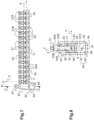
- the body 50 is pierced with a plurality of orifices 55 ( figures 3, 4 And 7 ) delimiting connection housings which extend along transverse axes Y parallel to each other and perpendicular to the longitudinal axis X. These orifices 55 are through and open onto two openings 55A formed in the first and second external faces 51, 52 of the body 50 ( Figures 3 and 4 ).
- Each mouthpiece 55A has a circular outline and each orifice 55 is delimited by a cylindrical internal face 55B whose longitudinal axis is the transverse axis Y of the corresponding connection housing ( Figures 3 and 4 ).
- connection housings are blind. These orifices then only open onto one of the first and second external faces of the body of the connection bar.
- the orifices and their mouths may also have any other suitable shape.
- the orifices 55 of the body 50 of the connecting bar 40 are regularly spaced along the longitudinal axis X of the connecting bar. They are arranged with a constant pitch along the longitudinal axis X. Furthermore, the mouths 55A of the orifices 55 all have the same shape and the same dimensions, i.e. here the same diameter. Alternatively, the mouths of the orifices and the orifices may have different shapes and/or dimensions.
- This diameter is suitable for the passage of the bare core of an electric wire with a cross-section of, for example, between 8 and 12 mm 2 , for example with a standard cross-section of 10 mm 2 .
- the body 50 of the connection bar 40 further comprises, in correspondence with each connection housing, a threaded conduit 56, with a central axis Z perpendicular to the longitudinal axes X and transverse axes Y, one end of which opens into said connection housing and the other end of which opens onto the third external face 53 longitudinal ( figures 3, 4 , 6 And 8 ).
- the central axis Z of each threaded conduit 56 will hereinafter be called the screwing axis Z.
- the 56 threaded conduits also all have the same dimensions.
- Each threaded conduit 56 is adapted to accommodate a clamping screw 57 ( figures 3, 4 , 6 And 8 ) comprising a head 57A and a threaded body 57B ( figures 4 And 7 ).
- the threaded body 57B of each clamping screw 57 is screwed into the corresponding threaded conduit 56 using a tool which is inserted into a slot in the head 57A of the clamping screw.
- connection cage 60 of the connection bar 40 is attached to the body 50 in place of a predetermined connection housing LP visible on the Figure 4 .
- This connection cage 60 is also made of conductive material.
- a single connection cage 60 is provided here.
- connection cage 60 thus comprises a base 61 and two parallel branches 62, 63 which rise from this base 61, perpendicular to it.
- connection cage 60 extend in directions substantially parallel to said screwing axes Z of the threaded conduits 56 of the body 50 of the connection bar 40 ( Figures 3 and 4 ).
- connection cage 60 internally delimits a receiving zone 68 for a part of the body 50 of the connection bar 40 comprising the predetermined connection housing LP which is replaced by the connection cage 60 ( Figures 3 and 4 ).
- the receiving zone 68 is located near the free ends of the branches 62, 63.
- the branches 62, 63 of the connection cage 60 are placed opposite said first and second longitudinal external faces 51, 52 of the body 50 of the connection bar 40. They are each arranged opposite one of the mouths 55A of the orifice 55 corresponding to the predetermined connection housing LP replaced by the connection cage 60, such that they close the mouths 55A of this orifice 55 ( figures 3 And 7 ).
- connection cage 60 extends on one side beyond the third external face 53 of the body 50 of the connection bar 40, and, on the other side, beyond the fourth external face 54 of this body 50.
- the bottom 61 of the connection cage 60 is arranged opposite the fourth external face 54 of the body 50 of the connection bar 40. It extends parallel to the latter ( figures 3 And 7 ).
- connection cage 60 also internally delimit a connection zone 64 accessible via at least a first opening 65 provided in a first of said branches 62 ( figures 3, 4 And 7 ).
- connection zone 64 is here also accessible via a second opening 66 provided in the second branch 63 ( Figures 3 and 4 ) of the connection cage 60, opposite the first opening 65.
- the first and second openings 65, 66 are located near the base 61 of the connection cage 60. Here they have a square outline with rounded corners and identical dimensions ( figures 3, 4 And 7 ). Other suitable forms may be considered.
- first and second openings 65, 66 are greater than those of the mouths 55A of the orifices 55 forming the connection housings of the body 50 of the connection bar.
- Each of the first and second openings 65, 66 is thus adapted to the passage of the stripped core of an electric cable, for example an electric power cable, with a section greater than that of an electric wire, for example with a section greater than or equal to 15 mm 2 , in particular equal to 16 or 25 mm 2 .
- connection zone 64 is located between the base 61 of the connection cage 60 and the receiving zone 68 of the body 50 of the connection bar 40. It extends between the internal face of the base 61 and the fourth external face 54 of the body of the connection bar 40 ( figures 3, 4 And 7 ).
- the two branches 62, 63 of the connection cage 60 comprise at their free ends returns 62A, 63A which extend parallel to the third longitudinal external face 53 of the body 50 of the connection bar 40 and are oriented towards each other ( figures 6 And 8 ).
- the returns 62A, 63A overlap opposite said third longitudinal external face 53 of the body 50 ( Figures 3 and 4 , 6 And 8 ).
- Each return 62A, 63A is pierced with a tapped hole 62B, 63B whose axis is aligned with the screwing axis Z of the tapped conduit 56 of the body 50 which opens into the housing of predetermined connection LP in place of which the connection cage 60 is installed ( figures 3,4 , 8 ).
- connection cage 60 and the tapped conduit 57 associated with the predetermined connection housing LP have identical diameters and are aligned, which allows them to accommodate a clamping screw 67 ( figures 6 And 8 ).
- the clamping screw 67 is adapted to be screwed into said tapped holes 62B, 63B and into said tapped conduit 56. For this purpose, it has a length greater than the length of the clamping screws 57 which are screwed into the tapped conduits 56 of the body 50 of the connecting bar 40 ( Figure 9 ).
- the clamping screw 67 nevertheless conventionally comprises a head 67A and a threaded body 67B ( Figure 4 ).
- the clamping screw 67 screwed into said tapped holes 62B, 63B and into said tapped conduit 56 ensures the maintenance of the connection cage 60 attached to the body 50.
- the clamping screw 67 rotates in the threaded conduit 56 without changing the relative position of the clamping screw 67 and the body 50 of the connecting bar along the screwing axis Z of the threaded conduit 56.
- the connecting cage 60 being free to slide around the body 50 of the connecting bar 40, the screwing of the clamping screw 67, in abutment against the internal face 55B of the orifice 55, causes the movement of the connecting cage 60 along the screwing axis Z of the threaded conduit 56, in the direction of the head 67A of the clamping screw 67.
- connection cage 60 is moved towards the fourth longitudinal external face 54 of the body 50 of the connection bar 40 (arrow F of the figure 8 ).
- connection bar 40 to electrically connect the electric cable to the connection bar 40, it is sufficient to introduce the stripped core of the electric cable into the connection zone 64 of the connection cage 60, then to screw the clamping screw 67 into the tapped holes 62B, 63B of the connection cage 60 and into the tapped conduit 56 of the body 50.
- the clamping screw 67 then comes into abutment against the internal face 55B of the orifice 55 corresponding to the predetermined connection housing LP and causes the movement of the connection cage 60 along of the axis of the clamping screw 67 which is coincident with the screwing axis Z of the corresponding threaded conduit so that the base 61 of the connection cage 60 comes to clamp the stripped core of the electric cable against the fourth external face 54 of the body 50 of the connection bar.
- the insulating envelope 10 which houses the connection bar 40 comprises a base 30 and at least one cover 20 ( figures 1, 2 , 5, 6 And 9 ). It is made, for example, by molding a plastic material.
- the base 30 has the shape of a chute extending along the longitudinal axis X of the body 50 of the connecting bar 40. It has a U-shaped cross section and is provided with a bottom 31 and two parallel longitudinal main walls 32, 33. It is closed at its longitudinal ends by transverse walls.
- At least one of these two main walls 32, 33 comprises two rows of windows 34A, 34B, 35 aligned in the direction of the longitudinal axis X.
- a first of the two main walls 32, called in the rest of the text the front main wall 32 comprises said two rows of windows 34A, 34B, 35, the second of the two main walls 33, called in the rest of the text the rear main wall 33, not comprising any window ( figures 1, 2 And 5 ).
- a first row of windows 34A, 34B is arranged near the longitudinal free edge of the front main wall 32.
- the windows 34A, 34B of this first row are circular in shape ( figures 1, 2 And 5 ). They have two different sizes: one window 34A out of two has a diameter substantially identical to that of the mouths 55A of the orifices 55 of the body 50 of the connecting bar 40, while the other windows 34B have a diameter slightly greater than that of the mouths 55A.
- the second row of windows 35 is arranged near the bottom 31 of the base 30.
- Each window 35 of this second row has a square shape with rounded corners, similar to the shape of the first and second openings 65, 66 formed in the branches 62, 63 of the connection cage 60, and dimensions slightly larger than those of these openings 65, 66 ( figures 1, 2 And 5 ).
- the windows 34A, 34B, 35 of the first and second row are arranged with a constant pitch along the longitudinal axis X.
- Each window 35 of the second row of windows of the base 30 is aligned in the direction of the screwing axis Z with one of the windows 34A, 34B of the first row of windows (see in particular the Figure 5 ).
- the 35 windows in the second row are arranged in correspondence with every other window in the first row. These are the 34B windows with the largest dimensions.
- the positions and dimensions of the windows 34A, 34B of the first row of windows are such that they are adapted to allow access to the connection housings of the body 50 of the connection bar 40, while each window 35 of the second row is adapted to allow access to the connection zone 64 of the connection cage 60.
- the windows 34A, 34B of the first row are thus generally centered on the transverse axes Y of the orifices 55 of the body of the connecting bar.
- the pitch separating two windows 34A, 34B of the first row is equal to the pitch separating two orifices 55 of the body 50 of the connecting bar.
- the base 30 further comprises a plurality of internal walls 36 which extend between each window 35 of the second row, perpendicular to the direction of the longitudinal axis X, from the front main wall 32 to the rear main wall 33, from the bottom 31 of the base 30 and over a predetermined height H in the direction of the screwing axis Z ( Figure 9 ).
- These internal walls 36 delimit with the bottom 31 and the main front and rear walls 32, 33 of the base 30 reception areas 37 adapted to receive a part of the connection cage 60 ( Figure 9 ).
- each reception zone 37 is adapted to receive the base 61 of the connection cage 60 and the parts of the branches 62, 63 which comprise the first and second openings 65, 66 and which delimit the connection zone 64 ( figures 6 And 9 ).
- connection bar 40 When positioning the connection bar 40 in the base 30 of the insulating envelope 10, the base 61 of the connection cage 60 is guided in one of the reception zones 37 of the base 30 by the internal walls 36 and the main front 32 and rear 33 walls of said base 30.
- the main front 32 and rear 33 walls of the base 30 extend opposite the branches 62, 63 of the connection cage 60, in the immediate vicinity of these. For this purpose, they are spaced by a distance slightly greater than the gap between the opposite faces of the two branches 62, 63, so as to allow the passage of the connection cage while guiding it.
- each receiving zone 37 along a plane transverse to the screwing axis Z are slightly greater than those of the base 61 of the connection cage 60.
- the internal walls 36 delimiting the corresponding receiving zone 37, closely frame the base 61 of the connection cage 60, so as to guide the latter and prevent any movement of the connection bar 40 along the longitudinal axis X.
- These internal walls 36 thus form longitudinal wedging stops for the connection bar 40 in the base 30.
- connection bar 40 is precisely fixed once the connection bar 40 is arranged in the base 30.
- the predetermined height of the internal walls 36 and the arrangement of the first and second rows of windows 34A, 34B, 35 are such that when the fourth face 54 of the body 50 of the connecting bar 40 rests on the free edge of said internal walls 36, each mouth 55A of each orifice 55, located on one of the first and second external faces 51, 52 of the body 50, is automatically placed opposite a window 34A, 34B of the first row of windows of the front main wall 32 of the base 30 and one of the openings 65, 66 of the connecting cage 60 is automatically arranged opposite one of the windows 35 of the second row ( figures 5 And 9 ) of the main front wall 32 of the base 30.
- the cover 20 of the insulating envelope 10 closes the base 30 opposite the third longitudinal external face 53 of the body 50 of the connection bar 40.
- the cover 20 of the insulating envelope 10 also has a U-shaped cross-section, with a flat base wall 21 and two curved longitudinal side wings 22 ( figures 1 , 5 and 6 ). It is closed at its longitudinal ends by transverse walls.
- the cover 20 and the base 30 are provided with complementary mounting means allowing the cover 20 to be attached to the base 30.
- the cover 20 comprises snap-fastening tabs 23 which extend from each lateral wing 22, projecting from its free edge, in the extension of the lateral wing. 22 (see in particular the Figure 6 ).
- Two snap-on tabs 23 are provided here on each side wing 22.
- the front 32 and rear 33 main walls of the base 30 comprise, along their longitudinal free edge, a sidewalk 38 formed by a local thinning of the corresponding front or rear main wall ( Figure 6 ).
- the end of each snap-fastening tab 23 of the cover 20 has a hooking tooth oriented towards the inside of the cover 20, which engages with the sidewall 38 of the base 30 to retain the cover 20 on the base 30 ( Figure 6 ).
- the free edge of the side wings 22 of the hood 20 then comes into contact with the front 32 and rear 33 main walls of the base 30 ( Figure 6 ).
- the cover 20 overhangs the connection bar 40 and comprises, in its base wall 21, opposite each threaded conduit 56 of said body 50, a bore 24 allowing the introduction of the tip of a tool to access the head of the clamping screw 57, 67 engaged in the corresponding threaded conduit 56 ( figures 1, 2 , 6 And 9 ).
- the cover 20 has a length less than that of the base 30. This length corresponds to the length of the connection bar 40.
- the base 30 can here advantageously accommodate several connection bars 40 and several covers 20 ( Figures 1 and 2 ).
- the number of holes 55 of the connecting bar 40 is equal to 15 and the number of windows of the first row is equal to 32.
- connection cage 60 is installed on any of the connection housings of the body 50.
- the body 50 is slid into the receiving zone 68 of the connection cage 60 and the clamping screw 67 is screwed through the tapped holes 62B, 63B of the branches of the connection cage and the tapped conduit 56 of the connection bar 50.
- connection cage 60 is positioned in place of the connection housing located at one of the ends of the body 50 of the connection bar 40.
- the connecting bar 40 is installed in the base 30 by sliding a part of the connecting cage 60 into one of the reception areas 37 of the base 30.
- the connecting bar 40 is automatically placed so that the mouths 55A of the orifices 55 of its body 50 are opposite the windows 34A, 34B of the first row of windows of the front main wall 32 of the base 30.
- the opening 65 giving access to the connection zone 64 of the connection cage 60 is also arranged opposite one of the windows of the second row of windows of the front main wall 32 of the base 30.
- the cover 20 is clipped onto the front and rear main walls 32, 33 of the base 30 so as to enclose the connection bar 40.
- connection area 64 of the connection cage 60 The user inserts the stripped core of an electric cable into the connection area 64 of the connection cage 60 through the window 35 of the front main wall 32 of the base 30 and the opening 65 of the connection cage 60. He screws the clamping screw 67 to move the base 61 of the connection cage 60 towards the fourth external face 54 of the body 50 of the connection bar 40 and, thus, clamp the stripped core of the electric cable between the base 61 of the connection cage 60 and the fourth external face 54 of the body 50 of the connection bar 40. Then, to supply an electrical appliance, the user inserts the stripped core of an electric wire into a connection housing of the connection bar 40, through the window 34A, 34B of the first row and the mouth 55A of one of the orifices 55 of the body 50 of the corresponding connection bar 40. It screws the clamping screw 57 to press the stripped core of the electric wire against the internal wall 55B of the hole 55 of the connection housing. The electrical connection between the electric cable and the electric wire is established.
Landscapes
- Connections Arranged To Contact A Plurality Of Conductors (AREA)
- Fuel Cell (AREA)
- Connections By Means Of Piercing Elements, Nuts, Or Screws (AREA)
Claims (12)
- Anschlußleiste (40) mit einem Körper (50) aus leitendem Material, der sich entlang einer Längsachse (X) erstreckt, mit einer ersten und einer zweiten längsgerichteten Außenseite (51, 52), die zueinander parallel sind, und einer dritten und einer vierten längsgerichteten Außenseite (53, 54), die zu der ersten und der zweiten Außenseite (51, 52) senkrecht sind, wobei der Körper (50) mit einer Anzahl Löcher (55) durchbohrt ist, die Verbindungsräume abgrenzen, die sich entlang zueinander paralleler und zur Längsachse (X) senkrechter Querachsen (Y) erstrecken und die an mindestens einer der ersten und zweiten längsgerichteten Außenseite (51, 52) münden,wobei der Körper (50) der Anschlußleiste (40) jedem Verbindungsraum entsprechend einen mit einem Innengewinde versehenen Gang (56) mit einer zur Längsachse (X) und zur Querachse (Y) senkrechten Mittelachse (Z) aufweist, von dem ein Ende in den Verbindungsraum mündet und von dem das andere Ende an der längsgerichteten dritten Außenseite (53) mündet,wobei die Anschlußleiste (40) an Stelle eines vorbestimmten Verbindungsraums (LP) einen Verbindungskäfig (60) aus leitendem Material aufweist, der U-förmig mit einer Basis (61) und zwei parallelen Zweigen (62, 63) ist, die im Inneren eine Verbindungszone (64) begrenzen, die über mindestens eine erste in einem ersten der Zweige (62) vorgesehen Öffnung (65) zugänglich ist, wobei die beiden Zweige (62, 63) gegenüber der ersten und der zweiten längsgerichteten Außenseite (51, 52) des Körpers (50) angeordnet sind und sich in zur zentralen Achse (Z) im Wesentlichen parallelen Richtungen außerhalb der dritten längsgerichteten Außenseite (53) erstrecken,dadurch gekennzeichnet, daß die beiden Zweige (62, 63) des Verbindungskäfigs (60) an deren freien Enden Abwinkelungen (62A, 63A) aufweisen, die sich gegenüber der dritten längsgerichteten Außenseite (53) des Körpers (50) überlappen, wobei die Abwinkelungen (62A, 63A) mit Gewindelöchern (62B, 63B) versehen sind, deren Achsen auf die zentrale Achse (Z) des mit einem Innengewinde versehenen Gangs (56) ausgerichtet sind, der in den vorbestimmten Verbindungsraum (LP) mündet und eine in die Gewindelöcher (62B, 63B) und in den mit einem Innengewinde versehenen Gang (56) eingeschraubte Klemmschraube (67) aufnimmt, wobei ein freies Ende der Klemmschraube (67) an einer Innenseite (55B) des vorbestimmten Verbindungsraums anliegt, so daß die Basis (61) des Verbindungskäfigs (60) beim Schrauben in Richtung auf die längsgerichtete vierte Außenseite (54) des Körpers (50) der Anschlußleiste (40) verlagert wird.
- Anschlußleiste (40) gemäß Anspruch 1, bei der jedes einen Verbindungsraum begrenzende Loch (55) ein Durchgangsloch ist und an der ersten und der zweiten längsgerichteten Außenseite (51, 52) des Körpers (50) mündet.
- Anschlußleiste (40) gemäß einem der Ansprüche 1 und 2, bei der die Verbindungszone (64) des Verbindungskäfigs (60) ebenfalls über eine im zweiten Zweig (63) des Verbindungskäfigs (60) gegenüber der ersten Öffnung (65) vorgesehene zweite Öffnung (66) zugänglich ist.
- Anschlußleiste (40) gemäß einem der Ansprüche 1 bis 3, bei der jeder Verbindungsraum mindestens eine in einer der ersten und der zweiten längsgerichteten Außenseite (51, 52) eingerichtete Mündung (55A) aufweist, wobei die in einem der Zweige (62) des Verbindungskäfigs (60) vorgesehene erste Öffnung (65) größere Abmessungen als die Abmessungen jeder Mündung (55A) aufweist.
- Anschlußleiste (40) gemäß einem der Ansprüche 1 bis 4, bei der der Verbindungskäfig (60) im Inneren eine Aufnahmezone (68) abgrenzt, die einen Teil des Körpers (50) der Anschlußleiste (40) mit dem vorbestimmten Verbindungsraum aufnimmt, wobei sich diese Aufnahmezone (68) zwischen den Abwinkelungen (62A, 62B) der Zweige (62, 63) und der Verbindungszone (64) befindet.
- Anschlußleiste (40) gemäß Anspruch 4, bei der die Zweige (62, 63) des Verbindungskäfigs (60) jede Mündung (55A) des vorbestimmten Verbindungsraums (LP) verschließen.
- Elektrische Reihenklemme (1) mit einer Anschlußleiste (40) gemäß einem der Ansprüche 1 bis 6 und einer isolierenden Umhüllung (10), die einen Sockel (30) und eine die Anschlußleiste (40) beherbergende Abdeckung (20) aufweist, wobei der Sockel (30) die Form einer sich entlang der Längsachse (X) der Anschlußleiste (40) erstreckenden Rinne mit einem Boden (31) und zwei parallelen längsgerichteten Hauptwandungen (32, 33) hat, wobei mindestens eine (32) dieser beiden längsgerichteten Hauptwandungen zwei gemäß der Richtung der Längsachse (X) ausgerichtete Fensterreihen (34A, 34B, 35) aufweist, wobei die Fenster (34A, 34B) einer ersten dieser beiden Reihen dazu ausgelegt sind, den Zugang zu den Verbindungsräumen des Körpers (50) der Anschlußleiste (40) zu ermöglichen, während jedes Fenster (35) der zweiten Reihe dazu ausgelegt ist, den Zugang zur Verbindungszone (64) des Verbindungskäfigs (60) zu ermöglichen.
- Elektrische Reihenklemme gemäß Anspruch 7, bei der die Fenster (35) der zweiten Reihe jedem zweiten Fenster (34B) der ersten Reihe entsprechend angeordnet sind, so daß die entsprechenden Fenster (34B, 35) der ersten und der zweiten Reihe gemäß der Richtung der zentralen Achse (Z) ausgerichtet sind.
- Elektrische Reihenklemme gemäß einem der Ansprüche 7 und 8, bei der der Sockel (30) eine Anzahl Innenwände (36) aufweist, die sich senkrecht zur Längsachse (X) von einer Hauptwand (32, 33) zur anderen zwischen jedem Fenster (35) der zweiten Reihe vom Boden (31) des Sockels (30) aus und in einer vorbestimmten Höhe (H) gemäß der Richtung der zentralen Achse (Z) erstrecken.
- Elektrische Reihenklemme gemäß dem vorangehenden Anspruch, bei der die vorbestimmte Höhe (H) so ist, daß, wenn die vierte Außenseite (54) des Körpers (50) der Anschlußleiste (40) auf dem freien Rand jeder Innenwand (36) ruht, die Fenster (34A, 34B) der ersten Reihe Fenster des Sockels (30) gegenüber den Mündungen (55A) der Verbindungsräume des Körpers (50) der Anschlußleiste (40) offen sind.
- Elektrische Reihenklemme gemäß einem der Ansprüche 9 und 10, bei der die Innenwände (36) mit dem Boden (31) und den Seitenwänden (32, 33) des Sockels (30) Aufnahmezonen (37) für einen Teil des Verbindungskäfigs (60) abgrenzen.
- Elektrische Reihenklemme gemäß einem der Ansprüche 7 bis 11, bei der die Abdeckung (20) der isolierenden Hülle (10) den Sockel (30) gegenüber der längsgerichteten dritten Außenseite (53) des Körpers (50) der Anschlußleiste (40) abschließt und gegenüber jedem mit einem Innengewinde versehenen Gang (56) des Körpers (50), der an dieser längsgerichteten dritten Außenseite (53) mündet, eine Bohrung (24) aufweist, die den Zugang zu einem Kopf einer in dem mit einem Innengewinde versehenen Gang (56) eingesetzten Klemmschraube (57, 67) ermöglicht.
Applications Claiming Priority (1)
| Application Number | Priority Date | Filing Date | Title |
|---|---|---|---|
| FR2212235A FR3142303B1 (fr) | 2022-11-23 | 2022-11-23 | Barre de connexion pourvue d’une cage de connexion et bornier électrique associé |
Publications (3)
| Publication Number | Publication Date |
|---|---|
| EP4376223A1 EP4376223A1 (de) | 2024-05-29 |
| EP4376223B1 true EP4376223B1 (de) | 2025-06-04 |
| EP4376223C0 EP4376223C0 (de) | 2025-06-04 |
Family
ID=85018705
Family Applications (1)
| Application Number | Title | Priority Date | Filing Date |
|---|---|---|---|
| EP23207177.9A Active EP4376223B1 (de) | 2022-11-23 | 2023-10-31 | Anschlussleiste mit einem leiterrahmen und zugehörige elektrische reihenklemme |
Country Status (3)
| Country | Link |
|---|---|
| EP (1) | EP4376223B1 (de) |
| CN (1) | CN118073876A (de) |
| FR (1) | FR3142303B1 (de) |
Family Cites Families (5)
| Publication number | Priority date | Publication date | Assignee | Title |
|---|---|---|---|---|
| US4231633A (en) * | 1978-09-26 | 1980-11-04 | Gould Inc. | Neutral bar, lug and barrier assembly |
| FR2750262B1 (fr) | 1996-06-21 | 1998-09-04 | Legrand Sa | Bornier |
| FR2858470B1 (fr) * | 2003-08-01 | 2008-09-26 | Mecelec Ind | Connecteur electrique |
| US7056163B2 (en) | 2004-09-20 | 2006-06-06 | Connector Manufacturing Company | Neutral bar with slide-on saddle lug |
| US7473146B2 (en) * | 2006-11-27 | 2009-01-06 | Tyco Electronics Brasil Ltda | Busbar assembly |
-
2022
- 2022-11-23 FR FR2212235A patent/FR3142303B1/fr active Active
-
2023
- 2023-10-31 EP EP23207177.9A patent/EP4376223B1/de active Active
- 2023-11-16 CN CN202311528878.8A patent/CN118073876A/zh active Pending
Also Published As
| Publication number | Publication date |
|---|---|
| CN118073876A (zh) | 2024-05-24 |
| EP4376223A1 (de) | 2024-05-29 |
| FR3142303A1 (fr) | 2024-05-24 |
| EP4376223C0 (de) | 2025-06-04 |
| FR3142303B1 (fr) | 2024-11-22 |
Similar Documents
| Publication | Publication Date | Title |
|---|---|---|
| FR2857510A1 (fr) | Dispositif de connexion pour cable coaxial | |
| EP0619625A1 (de) | Elektrischer Verbinder mit einer Anzahl von Modulen in Reihen und Kolonnen geordnet | |
| CA1283959C (fr) | Dispositif de connexion | |
| EP4376223B1 (de) | Anschlussleiste mit einem leiterrahmen und zugehörige elektrische reihenklemme | |
| EP3089295B1 (de) | Elektrische verbindungsvorrichtung zur spannungsausgleichsverbindung von einem kabelrinnenabschnitt mit eines stromkabelabschnitts | |
| EP0062579B1 (de) | Verbindungsgerät | |
| FR3029698A1 (fr) | Element de connexion electrique a percage de gaine isolante d'un fil electrique | |
| EP2662931B1 (de) | Anschlussschuh für isoliertes elektrisches Netzkabel, und Herstellungsverfahren dieses Anschlussschuhs | |
| FR2541049A1 (fr) | Dispositif de connexion autodenudant | |
| EP0852824A1 (de) | Verbindungsvorrichtung für mindestens zwei ummantelden leitenden drähte | |
| EP1655806B1 (de) | Verbinder, Sammelschienenadapter mit Verbinder und Verteilergehäuse mit Sammelschienenadapter und Verbinder | |
| WO1986003063A1 (fr) | Dispositif de connexion | |
| EP0251909B2 (de) | Verbindungselement für ein elektrisches Monoleiterkabel zur axialen Verbindung | |
| EP0642193A1 (de) | Schneidklemmverbinder | |
| EP0172779B1 (de) | Mehrpoliger elektrischer Verbinder | |
| EP4131659B1 (de) | Steckdosenmechanismus und entsprechende steckdose | |
| WO2018109402A1 (fr) | Element de connexion electrique muni d'un element de contact | |
| EP3336967B1 (de) | Elektrisches anschlusselement | |
| FR2819348A1 (fr) | Connexion autodenudante a fente convergente | |
| EP4280387B1 (de) | Elektrische anschlussleiste mit einem steckerelement und einem elektrischen anschlussbuchsenelement | |
| FR3126072A1 (fr) | Borne de connexion automatique comprenant deux zones de contact et mécanisme d’appareillage électrique associé | |
| FR2896626A1 (fr) | Bloc de borne de connexion | |
| EP3312948B1 (de) | Elektrische steckdose, die ein monoblockteil zur halterung und aufnahme von höckereinsätzen umfasst, und verfahren zum zusammenbau einer solchen elektrischen steckdose | |
| FR2507393A1 (fr) | Borne de contact electrique pour branchement rapide d'un conducteur isole | |
| FR2737048A1 (fr) | Element de connexion a connexion axiale pour conducteur electrique |
Legal Events
| Date | Code | Title | Description |
|---|---|---|---|
| PUAI | Public reference made under article 153(3) epc to a published international application that has entered the european phase |
Free format text: ORIGINAL CODE: 0009012 |
|
| STAA | Information on the status of an ep patent application or granted ep patent |
Free format text: STATUS: THE APPLICATION HAS BEEN PUBLISHED |
|
| AK | Designated contracting states |
Kind code of ref document: A1 Designated state(s): AL AT BE BG CH CY CZ DE DK EE ES FI FR GB GR HR HU IE IS IT LI LT LU LV MC ME MK MT NL NO PL PT RO RS SE SI SK SM TR |
|
| STAA | Information on the status of an ep patent application or granted ep patent |
Free format text: STATUS: REQUEST FOR EXAMINATION WAS MADE |
|
| 17P | Request for examination filed |
Effective date: 20240918 |
|
| RAV | Requested validation state of the european patent: fee paid |
Extension state: TN Effective date: 20240918 Extension state: MA Effective date: 20240918 |
|
| RBV | Designated contracting states (corrected) |
Designated state(s): AL AT BE BG CH CY CZ DE DK EE ES FI FR GB GR HR HU IE IS IT LI LT LU LV MC ME MK MT NL NO PL PT RO RS SE SI SK SM TR |
|
| REG | Reference to a national code |
Ref country code: DE Ref legal event code: R079 Free format text: PREVIOUS MAIN CLASS: H01R0004360000 Ipc: H01R0009240000 Ref country code: DE Ref legal event code: R079 Ref document number: 602023003838 Country of ref document: DE Free format text: PREVIOUS MAIN CLASS: H01R0004360000 Ipc: H01R0009240000 |
|
| GRAP | Despatch of communication of intention to grant a patent |
Free format text: ORIGINAL CODE: EPIDOSNIGR1 |
|
| STAA | Information on the status of an ep patent application or granted ep patent |
Free format text: STATUS: GRANT OF PATENT IS INTENDED |
|
| RIC1 | Information provided on ipc code assigned before grant |
Ipc: H01R 9/24 20060101ALI20250121BHEP Ipc: H01R 4/36 20060101AFI20250121BHEP |
|
| RIC1 | Information provided on ipc code assigned before grant |
Ipc: H01R 11/07 20060101ALN20250127BHEP Ipc: H01R 4/36 20060101ALI20250127BHEP Ipc: H01R 9/24 20060101AFI20250127BHEP |
|
| INTG | Intention to grant announced |
Effective date: 20250213 |
|
| GRAS | Grant fee paid |
Free format text: ORIGINAL CODE: EPIDOSNIGR3 |
|
| GRAA | (expected) grant |
Free format text: ORIGINAL CODE: 0009210 |
|
| STAA | Information on the status of an ep patent application or granted ep patent |
Free format text: STATUS: THE PATENT HAS BEEN GRANTED |
|
| AK | Designated contracting states |
Kind code of ref document: B1 Designated state(s): AL AT BE BG CH CY CZ DE DK EE ES FI FR GB GR HR HU IE IS IT LI LT LU LV MC ME MK MT NL NO PL PT RO RS SE SI SK SM TR |
|
| REG | Reference to a national code |
Ref country code: GB Ref legal event code: FG4D Free format text: NOT ENGLISH |
|
| REG | Reference to a national code |
Ref country code: CH Ref legal event code: EP |
|
| REG | Reference to a national code |
Ref country code: IE Ref legal event code: FG4D Free format text: LANGUAGE OF EP DOCUMENT: FRENCH |
|
| U01 | Request for unitary effect filed |
Effective date: 20250606 |
|
| U07 | Unitary effect registered |
Designated state(s): AT BE BG DE DK EE FI FR IT LT LU LV MT NL PT RO SE SI Effective date: 20250616 |
|
| U20 | Renewal fee for the european patent with unitary effect paid |
Year of fee payment: 3 Effective date: 20250829 |
|
| PG25 | Lapsed in a contracting state [announced via postgrant information from national office to epo] |
Ref country code: ES Free format text: LAPSE BECAUSE OF FAILURE TO SUBMIT A TRANSLATION OF THE DESCRIPTION OR TO PAY THE FEE WITHIN THE PRESCRIBED TIME-LIMIT Effective date: 20250604 |
|
| PG25 | Lapsed in a contracting state [announced via postgrant information from national office to epo] |
Ref country code: NO Free format text: LAPSE BECAUSE OF FAILURE TO SUBMIT A TRANSLATION OF THE DESCRIPTION OR TO PAY THE FEE WITHIN THE PRESCRIBED TIME-LIMIT Effective date: 20250904 Ref country code: GR Free format text: LAPSE BECAUSE OF FAILURE TO SUBMIT A TRANSLATION OF THE DESCRIPTION OR TO PAY THE FEE WITHIN THE PRESCRIBED TIME-LIMIT Effective date: 20250905 |
|
| PG25 | Lapsed in a contracting state [announced via postgrant information from national office to epo] |
Ref country code: PL Free format text: LAPSE BECAUSE OF FAILURE TO SUBMIT A TRANSLATION OF THE DESCRIPTION OR TO PAY THE FEE WITHIN THE PRESCRIBED TIME-LIMIT Effective date: 20250604 |
|
| PG25 | Lapsed in a contracting state [announced via postgrant information from national office to epo] |
Ref country code: HR Free format text: LAPSE BECAUSE OF FAILURE TO SUBMIT A TRANSLATION OF THE DESCRIPTION OR TO PAY THE FEE WITHIN THE PRESCRIBED TIME-LIMIT Effective date: 20250604 |
|
| PG25 | Lapsed in a contracting state [announced via postgrant information from national office to epo] |
Ref country code: RS Free format text: LAPSE BECAUSE OF FAILURE TO SUBMIT A TRANSLATION OF THE DESCRIPTION OR TO PAY THE FEE WITHIN THE PRESCRIBED TIME-LIMIT Effective date: 20250904 |
|
| PG25 | Lapsed in a contracting state [announced via postgrant information from national office to epo] |
Ref country code: IS Free format text: LAPSE BECAUSE OF FAILURE TO SUBMIT A TRANSLATION OF THE DESCRIPTION OR TO PAY THE FEE WITHIN THE PRESCRIBED TIME-LIMIT Effective date: 20251004 |
|
| PG25 | Lapsed in a contracting state [announced via postgrant information from national office to epo] |
Ref country code: SM Free format text: LAPSE BECAUSE OF FAILURE TO SUBMIT A TRANSLATION OF THE DESCRIPTION OR TO PAY THE FEE WITHIN THE PRESCRIBED TIME-LIMIT Effective date: 20250604 |
|
| PG25 | Lapsed in a contracting state [announced via postgrant information from national office to epo] |
Ref country code: CZ Free format text: LAPSE BECAUSE OF FAILURE TO SUBMIT A TRANSLATION OF THE DESCRIPTION OR TO PAY THE FEE WITHIN THE PRESCRIBED TIME-LIMIT Effective date: 20250604 |
|
| PG25 | Lapsed in a contracting state [announced via postgrant information from national office to epo] |
Ref country code: SK Free format text: LAPSE BECAUSE OF FAILURE TO SUBMIT A TRANSLATION OF THE DESCRIPTION OR TO PAY THE FEE WITHIN THE PRESCRIBED TIME-LIMIT Effective date: 20250604 |
|
| VS25 | Lapsed in a validation state [announced via postgrant information from nat. office to epo] |
Ref country code: MA Free format text: FAILURE TO ELECT DOMICILE IN THE NATIONAL COUNTRY Effective date: 20250905 |
|
| VS25 | Lapsed in a validation state [announced via postgrant information from nat. office to epo] |
Ref country code: MA Free format text: LAPSE BECAUSE OF FAILURE TO SUBMIT A TRANSLATION OF THE DESCRIPTION OR TO PAY THE FEE WITHIN THE PRESCRIBED TIME-LIMIT Effective date: 20250604 |
|
| PLBE | No opposition filed within time limit |
Free format text: ORIGINAL CODE: 0009261 |
|
| STAA | Information on the status of an ep patent application or granted ep patent |
Free format text: STATUS: NO OPPOSITION FILED WITHIN TIME LIMIT |
|
| REG | Reference to a national code |
Ref country code: CH Ref legal event code: L10 Free format text: ST27 STATUS EVENT CODE: U-0-0-L10-L00 (AS PROVIDED BY THE NATIONAL OFFICE) Effective date: 20260416 |