EP4376230A1 - Procédé et système de connexion aveugle - Google Patents
Procédé et système de connexion aveugle Download PDFInfo
- Publication number
- EP4376230A1 EP4376230A1 EP23191661.0A EP23191661A EP4376230A1 EP 4376230 A1 EP4376230 A1 EP 4376230A1 EP 23191661 A EP23191661 A EP 23191661A EP 4376230 A1 EP4376230 A1 EP 4376230A1
- Authority
- EP
- European Patent Office
- Prior art keywords
- main
- connector
- connectors
- along
- auxiliary
- Prior art date
- Legal status (The legal status is an assumption and is not a legal conclusion. Google has not performed a legal analysis and makes no representation as to the accuracy of the status listed.)
- Pending
Links
- 238000000034 method Methods 0.000 title claims abstract description 62
- 238000006073 displacement reaction Methods 0.000 claims abstract description 100
- 238000003780 insertion Methods 0.000 claims description 97
- 230000037431 insertion Effects 0.000 claims description 97
- 230000008878 coupling Effects 0.000 claims description 11
- 238000010168 coupling process Methods 0.000 claims description 11
- 238000005859 coupling reaction Methods 0.000 claims description 11
- 230000014759 maintenance of location Effects 0.000 claims description 9
- FGUUSXIOTUKUDN-IBGZPJMESA-N C1(=CC=CC=C1)N1C2=C(NC([C@H](C1)NC=1OC(=NN=1)C1=CC=CC=C1)=O)C=CC=C2 Chemical compound C1(=CC=CC=C1)N1C2=C(NC([C@H](C1)NC=1OC(=NN=1)C1=CC=CC=C1)=O)C=CC=C2 FGUUSXIOTUKUDN-IBGZPJMESA-N 0.000 claims description 4
- 230000001419 dependent effect Effects 0.000 claims 1
- 230000008901 benefit Effects 0.000 description 25
- 230000013011 mating Effects 0.000 description 12
- 230000008569 process Effects 0.000 description 10
- 238000012986 modification Methods 0.000 description 3
- 230000004048 modification Effects 0.000 description 3
- 230000001939 inductive effect Effects 0.000 description 2
- 238000013459 approach Methods 0.000 description 1
- 230000000295 complement effect Effects 0.000 description 1
- 230000006835 compression Effects 0.000 description 1
- 238000007906 compression Methods 0.000 description 1
- 230000000694 effects Effects 0.000 description 1
- 230000007246 mechanism Effects 0.000 description 1
- 230000000717 retained effect Effects 0.000 description 1
Images


Classifications
-
- H—ELECTRICITY
- H01—ELECTRIC ELEMENTS
- H01R—ELECTRICALLY-CONDUCTIVE CONNECTIONS; STRUCTURAL ASSOCIATIONS OF A PLURALITY OF MUTUALLY-INSULATED ELECTRICAL CONNECTING ELEMENTS; COUPLING DEVICES; CURRENT COLLECTORS
- H01R13/00—Details of coupling devices of the kinds covered by groups H01R12/70 or H01R24/00 - H01R33/00
- H01R13/62—Means for facilitating engagement or disengagement of coupling parts or for holding them in engagement
- H01R13/629—Additional means for facilitating engagement or disengagement of coupling parts, e.g. aligning or guiding means, levers, gas pressure electrical locking indicators, manufacturing tolerances
- H01R13/631—Additional means for facilitating engagement or disengagement of coupling parts, e.g. aligning or guiding means, levers, gas pressure electrical locking indicators, manufacturing tolerances for engagement only
- H01R13/6315—Additional means for facilitating engagement or disengagement of coupling parts, e.g. aligning or guiding means, levers, gas pressure electrical locking indicators, manufacturing tolerances for engagement only allowing relative movement between coupling parts, e.g. floating connection
-
- H—ELECTRICITY
- H01—ELECTRIC ELEMENTS
- H01R—ELECTRICALLY-CONDUCTIVE CONNECTIONS; STRUCTURAL ASSOCIATIONS OF A PLURALITY OF MUTUALLY-INSULATED ELECTRICAL CONNECTING ELEMENTS; COUPLING DEVICES; CURRENT COLLECTORS
- H01R12/00—Structural associations of a plurality of mutually-insulated electrical connecting elements, specially adapted for printed circuits, e.g. printed circuit boards [PCB], flat or ribbon cables, or like generally planar structures, e.g. terminal strips, terminal blocks; Coupling devices specially adapted for printed circuits, flat or ribbon cables, or like generally planar structures; Terminals specially adapted for contact with, or insertion into, printed circuits, flat or ribbon cables, or like generally planar structures
- H01R12/70—Coupling devices
- H01R12/91—Coupling devices allowing relative movement between coupling parts, e.g. floating or self aligning
-
- H—ELECTRICITY
- H01—ELECTRIC ELEMENTS
- H01R—ELECTRICALLY-CONDUCTIVE CONNECTIONS; STRUCTURAL ASSOCIATIONS OF A PLURALITY OF MUTUALLY-INSULATED ELECTRICAL CONNECTING ELEMENTS; COUPLING DEVICES; CURRENT COLLECTORS
- H01R13/00—Details of coupling devices of the kinds covered by groups H01R12/70 or H01R24/00 - H01R33/00
- H01R13/62—Means for facilitating engagement or disengagement of coupling parts or for holding them in engagement
- H01R13/629—Additional means for facilitating engagement or disengagement of coupling parts, e.g. aligning or guiding means, levers, gas pressure electrical locking indicators, manufacturing tolerances
- H01R13/631—Additional means for facilitating engagement or disengagement of coupling parts, e.g. aligning or guiding means, levers, gas pressure electrical locking indicators, manufacturing tolerances for engagement only
-
- H—ELECTRICITY
- H01—ELECTRIC ELEMENTS
- H01R—ELECTRICALLY-CONDUCTIVE CONNECTIONS; STRUCTURAL ASSOCIATIONS OF A PLURALITY OF MUTUALLY-INSULATED ELECTRICAL CONNECTING ELEMENTS; COUPLING DEVICES; CURRENT COLLECTORS
- H01R13/00—Details of coupling devices of the kinds covered by groups H01R12/70 or H01R24/00 - H01R33/00
- H01R13/73—Means for mounting coupling parts to apparatus or structures, e.g. to a wall
- H01R13/74—Means for mounting coupling parts in openings of a panel
-
- H—ELECTRICITY
- H01—ELECTRIC ELEMENTS
- H01R—ELECTRICALLY-CONDUCTIVE CONNECTIONS; STRUCTURAL ASSOCIATIONS OF A PLURALITY OF MUTUALLY-INSULATED ELECTRICAL CONNECTING ELEMENTS; COUPLING DEVICES; CURRENT COLLECTORS
- H01R43/00—Apparatus or processes specially adapted for manufacturing, assembling, maintaining, or repairing of line connectors or current collectors or for joining electric conductors
- H01R43/26—Apparatus or processes specially adapted for manufacturing, assembling, maintaining, or repairing of line connectors or current collectors or for joining electric conductors for engaging or disengaging the two parts of a coupling device
-
- H—ELECTRICITY
- H01—ELECTRIC ELEMENTS
- H01R—ELECTRICALLY-CONDUCTIVE CONNECTIONS; STRUCTURAL ASSOCIATIONS OF A PLURALITY OF MUTUALLY-INSULATED ELECTRICAL CONNECTING ELEMENTS; COUPLING DEVICES; CURRENT COLLECTORS
- H01R13/00—Details of coupling devices of the kinds covered by groups H01R12/70 or H01R24/00 - H01R33/00
- H01R13/62—Means for facilitating engagement or disengagement of coupling parts or for holding them in engagement
- H01R13/629—Additional means for facilitating engagement or disengagement of coupling parts, e.g. aligning or guiding means, levers, gas pressure electrical locking indicators, manufacturing tolerances
Definitions
- the present invention generally refers to the technical field of electrical connections and, in particular to a method and a system for realizing blind connections.
- male and female electrical connectors each of which includes a dielectric housing and at least one electrical terminal securely mounted therein.
- the male and female connectors may be advantageously assembled by means of an automated machine.
- a blind connection which is a connection that does not require any assistance from human operators and that can automatically compensate for significant misalignments along directions perpendicular to the insertion direction.
- it may be necessary to automatically compensate for misalignments along the insertion direction for instance when the male and female connectors are not perfectly parallel to each other.
- blind connection systems are known at the state of the art and are described for instance in patent applications EP 0 702 429 and DE 10 2019 211 563 .
- the blind connection systems known at the state of the art do not allow overcoming large misalignments along directions perpendicular to the insertion direction, such as misalignments of ⁇ 4 mm.
- the blind connection systems known at the state of the art do not allow overcoming also misalignments along the insertion direction.
- the present invention is hence directed to providing a method for realizing a blind connection and a blind connection system which solve these and other problems of the prior art.
- the present invention is based on the idea of providing a method for realizing a blind connection between a main first and a main second connectors, wherein the position of the main second connector is automatically adjusted so as to coaxially align it with the main first connector along at least one of the directions perpendicular to the insertion direction, thanks to the structure of both connectors. Moreover, the present invention is based on the idea of providing a method for realizing a blind connection between a main first and a main second connectors, wherein the position of the main second connector is automatically adjusted so as to align the two connectors along the insertion direction by means of a plurality of elastic means configured to apply a compensation force on the main second connector.
- the present invention refers to a blind connection system comprising a main first and second connectors, wherein the blind connection system is designed in such a way as to displace the main second connector along at least one direction perpendicular to the insertion direction, in order to coaxially align them in an automated way.
- the present invention refers to a blind connection system comprising a main first connector and a main second connector, wherein a plurality of elastic means is associated to the two connectors and is configured to apply a compensation force on the main second connector so as to align them and make them parallel to each other.
- a method for realizing a blind connection between a first connector and a second connector comprising the following steps:
- the advantage of this configuration is that it allows overcoming a large misalignment along directions perpendicular to the insertion direction. Moreover, the present method can be carried out in automated processes wherein alignment gaps cannot be recovered by human feedback.
- the main first connector may be a male connector or a female connector, i.e. it may comprise male electrical terminals or female electrical terminals;
- the main second connector may be a male connector or a female connector, depending on the type of the main first connector, so that the pair of main first and second connectors form a pair of male and female connectors.
- each auxiliary first connector may be a male connector or a female connector, i.e.
- each auxiliary second connector may be a male connector or a female connector, depending on the type of the corresponding auxiliary first connector, so that each pair of auxiliary first and second connectors form a pair of male and female connectors.
- the coaxial alignment along the displacement directions perpendicular to the insertion direction indicates that the main axis of the connectors are aligned along these directions within a predefined range so as to ensure the electrical connection between the two connectors.
- the main axes of the main first and second connectors are aligned, so as to ensure a secure and stable electrical connection between the electrical contacts of the main first and second connectors.
- the main axes of the pins and the corresponding holes are aligned within a second predefined range, so as to ensure a secure and stable electrical connection between electrical contacts of other electrical components formed on the main first and second connectors.
- the angle formed between the main axis of the main first connector and the main axis of the main second connector is reduced with respect to the initial position of the two connectors, so as to ensure a secure and stable electrical connection between the electrical contacts of the main first and second connectors.
- the angle formed between the main axis of each pin and the main axis of each corresponding hole is reduced with respect to the initial configuration, so as to ensure a secure and stable electrical connection between the electrical contacts of other electrical components formed on the main first and second connectors.
- the main first connector and the main second connector are designed so as to have a slanted surface at their extremities, for instance having a chamfer, in order to induce a displacement of the main second connector during the insertion step and to align the two connectors before mating the corresponding electrical contacts.
- the blind connection between the main first connector and the main second connector comprises two steps, carried out one after the other:
- the main first connector is fixed.
- the one or more pins are fixed.
- the pins may be integral parts of the main first connector.
- the holes and the pins for fine alignment may be holes and pins provided only for alignment purposes, that is not having any electrical connection function.
- the first force acting on the main second connector is created after contacting the slanted surface of the main first connector with the slanted surface of the main second connector, as a result of applying an insertion force for inserting the main second connector into the main first connector so as to obtain the electrical contact.
- the second force acting on the holes is created as a result of applying an insertion force for inserting the pins into the corresponding holes.
- a method for realizing a blind connection wherein the first slanted surface of the main first connector and the second slanted surface of the main second connector have the same slope and the step e) is carried out by sliding the main second connector into the main first connector.
- first slanted surface and the second slanted surface have the same slope is advantageous because it favors inserting the main second connector into the main first connector and helps creating the first force, which induces the alignment.
- a method for realizing a blind connection wherein the displacement along at least one of the displacement directions is comprised between 0 mm and 8 mm, preferably between 2 mm and 6 mm, even more preferably equal to 4 mm.
- the advantage of this configuration is that it allows automatically compensating for large misalignments between the main first and second connectors, for instance misalignments in the range comprised between 0 mm and 8 mm, preferably between 2 mm and 6 mm, even more preferably equal to 4 mm.
- a method for realizing a blind connection comprising the following step: g) Providing the main first connector with one or more auxiliary first connectors and providing the main second connector with one or more auxiliary second connectors mechanically connected to the one or more holes, the one or more auxiliary first connectors being configured to be mated with the corresponding one or more auxiliary second connectors; Wherein, during the step f), the one or more auxiliary second connectors are also displaced together with the one or more holes and a fine coaxial alignment between the one or more auxiliary first connectors and the corresponding one or more auxiliary second connectors along the displacement direction is obtained.
- This method ensures a stable and secure electrical connection not only between the main first and second connectors, but also between the auxiliary first connectors and the corresponding auxiliary second connectors. Moreover, this method allows compensating for large misalignment between each pair of connectors independently from each other.
- the pins of the main first connector are preferably integrally formed on the main first connector.
- the holes of the main second connector are mechanically connected to the one or more auxiliary second connectors formed on the main second connector, so as to form a rigid structure.
- a second force is created, which induces lateral displacement of the holes and, accordingly, of the auxiliary second connectors connected to the holes, so as to align them with the corresponding auxiliary first connectors and obtain an electrical connection.
- the one or more auxiliary first connectors have a funnel shape at their extremities and the one or more auxiliary second connectors have a tapered shape at their extremities. In this way, displacement of the one or more second connectors in favoured.
- a method for realizing a blind connection wherein each pin has a third extremity with a third slanted surface and each hole has a fourth extremity with a fourth slanted surface, so that the step f) is carried out by sliding the one or more holes onto the one or more pins.
- a method for realizing a blind connection wherein the one or more auxiliary second connectors are displaced with respect to an integral support element of the main second connector.
- this method allows obtaining a stable and secure electrical connection not only between the main first and second connectors, but also between the auxiliary first connectors and the corresponding auxiliary second connectors.
- a method for realizing a blind connection comprising the following step: h) Generating a compensation force along the insertion direction by means of a plurality of elastic means, whereby a displacement of at least one part of the main second connector along the insertion direction is induced by the compensation force, so as to compensate for any non-parallelism between the main first connector and the main second connector.
- the advantage of this configuration is that it allows overcoming misalignments along the insertion directions, for instance when the main first connector and the main second connector are not parallel with respect to each other.
- the present solution hence allows recovering planarity errors during the assembly process, thanks to the fact that the elastic means can self-adjust and can recover planarity errors in the space.
- the main first connector is fixed.
- a method for realizing a blind connection between a main first connector and a main second connector comprising the following steps:
- the advantage of this configuration is that it allows overcoming large misalignment gaps between at least one portion of the main first connector and at least one portion of the main second connector along the insertion direction.
- the method according to the present invention allows overcoming and recovering the planarity error, thanks to the fact that the elastic means can self-adjust.
- the method of the present invention may induce a tilt of the main second connector so as make it parallel to the main first connector, which is fixed.
- the method according to the present invention allows overcoming misalignment gaps along the insertion direction and/or along one or more directions parallel to the insertion direction, wherein a misalignment along a single direction can be compensated for independently from the other directions.
- a method for realizing a blind connection wherein the main first connector and the main second connector are connected by means of coupling elements and the elastic means are arranged within the coupling elements.
- the elastic means comprised within the coupling elements may be positioned between the main first connector and the main second connector and may induce an adjustment of the position of the main second connector.
- the elastic means may be positioned only in contact with the main second connector, so as to induce an adjustment of the position of the main second connector.
- a method for realizing a blind connection wherein the displacement along the insertion direction is comprised between 0 mm and 8 mm, preferably between 2 mm and 6 mm, even more preferably is equal to 4 mm.
- the advantage of the configuration is that it allows compensating for large misalignments, for instance misalignments in the range comprised between 0 mm and 8 mm, preferably between 2mm and 6mm, even more preferably equal to 4 mm.
- a method for realizing a blind connection comprising the following steps:
- This method is advantageous because the centering elastic elements ensure that the main second connector is in a stable, centered position, thus facilitating the mating between the main first and second connectors.
- a method for realizing a blind connection comprising the following steps:
- This method is advantageous because the centering elastic elements ensure that the main second connector is self-centered with respect to the compensation frame.
- a blind connection system comprising the following elements:
- the main second connector is configured in such a way as to be displaced along at least one displacement direction perpendicular to the insertion direction, when at least one portion of the second slanted surface of the main second connector contacts at least one portion of the first slanted surface of the main first connector and the main second connector is inserted in the main first connector, in order to induce a coarse coaxial alignment with the main first connector along the displacement direction; and when the pin is inserted in the hole along the insertion direction, the hole is displaced along at least one displacement direction perpendicular to the insertion direction, in order to induce a fine coaxial alignment with the pin along the displacement direction.
- this blind connection system is that it can be used in automated processes when alignment without assistance of any human operator is required and it can overcome large misalignments between the main second and the main first connectors.
- the blind connection system according to the present invention is easy to assemble and versatile and it can be used in many applications requiring electrical connectors, for instance with engines.
- the funnel shape of the first extremity of the main first connector in combination with the tapered shape of the first extremity of the main second connector allow the position of the main second connector to be gradually readjusted and the main second connector to gradually align with the main first connector, in order to help the main second connector to be plugged into the main first connector. In this way, blind mating of the two connectors is permitted, even if the main first connector and the main second connector were initially misaligned with one another.
- the blind connection system may be made with a rigid, non-deformable material.
- a blind connection system wherein the first slanted surface of the main first connector and the second slanted surface of the main second connector have the same slope so as to favor sliding of the main second connector into the main first connector.
- the advantage of this configuration is that insertion of the main second connector into the main first connector is favored thanks to the complementary slanted surface of the two connectors. Moreover, the fact that the slanted surfaces form an extended portion of the extremities of the main second and of the main first connector allows overcoming misalignments between the two connectors already during the approaching phase, not only during the mating phase, thus simplifying the alignment process.
- the slanted portions are made with a smooth material so as to favor sliding of the main second connector into the main first connector.
- the dimensions of the first and second slanted surfaces are designed so as to be adapted to the magnitude of the misalignment between the two connectors that must be compensated for.
- each slanted surface defines a tip, for instance a chamfered tip.
- the thickness of each slanted surface at maximum distance from the tip may be designed to be substantially equal to half of the value of the misalignment that must be compensated for.
- the first and the second slanted surfaces may be designed so that the thickness of the first slanted surface at maximum distance from the tip is comprised in the range between 2 mm and 3 mm, preferably equal to 2.5 mm and the thickness of the second slanted surface at maximum distance from the tip is comprised in the range between 2 mm and 3 mm, preferably equal to 2.5 mm.
- a blind connection system wherein the main first connector is further provided with one or more auxiliary first connectors and the main second connector is further provided with one or more auxiliary second connectors mechanically connected to the one or more holes, the one or more auxiliary first connectors being configured to be mated with the corresponding one or more auxiliary second connectors.
- the one or more auxiliary second connectors are displaced along the at least one displacement direction together with the holes and a fine coaxial alignment between the one or more auxiliary first connectors and the one or more auxiliary second connectors along the displacement direction is obtained.
- a blind connection system wherein each pin has a third extremity with a third slanted surface and each hole has a fourth extremity with a fourth slanted surface, so as to favour sliding of the one or more pins into the one or more holes.
- a blind connection system wherein the one or more auxiliary second connectors are movable along guiding means formed on an integral support element of the main second connector with respect to the support element.
- this system allows obtaining a stable and secure electrical connection not only between the main first and second connectors, but also between the auxiliary first connectors and the corresponding auxiliary second connectors.
- the auxiliary first and second connectors may be assembled to the main first and second connectors, respectively, at a later stage of the assembly process. Therefore, due to assembly errors, the misalignment between the main first and second connectors may differ from the misalignment between the auxiliary first and second connectors. Accordingly, making the movement of the auxiliary connectors independent from the movement of the main connectors allows obtaining fine alignment, in the event that the auxiliary first and second connectors are still misaligned after coarse alignment of the main first and second connectors.
- a blind connection system further comprising a compensation frame placed between the main first connector and the main second connector, wherein the compensation frame comprises a plurality of elastic means configured to generate a compensation force and induce a displacement of at least one part of the main second connector along the insertion direction, so as to compensate for any non parallelism between the main first connector and the main second connector.
- the advantage of this configuration is that the compensation frame can be easily assembled to the main second connector and the main first connector and it can overcome any misalignment along the insertion direction, for instance any misalignment due to a non-correct assembly of the two connectors.
- the compensation frame provided with elastic means may advantageously compensate for additional strokes in the insertion direction during the assembly process.
- the electrical connection between the main first connector and the main second connector is not damaged nor affected by the movement of the elastic means.
- a blind connection system comprising the following elements:
- the compensation frame may induce a displacement of at least one part of the main second connector along the insertion direction so as to make the main first and second connectors parallel to each other.
- the compensation frame may induce a tilt of the main second connector so that at the end of the tilting process the two connectors are parallel to each other.
- the electrical connection between the main second connector and the main first connector is not damaged nor affected by the movement of the elastic means.
- a blind connection system may be provided that overcomes misalignments along the directions perpendicular to the insertion direction.
- a blind connection system may be provided that overcomes misalignments only along the insertion direction.
- a blind connection system may be provided that overcomes misalignments along the directions perpendicular to the insertion direction and also along the insertion direction.
- a coarse coaxial alignment between the main first and second connectors along the displacement directions perpendicular to the insertion direction is obtained; subsequently, a fine coaxial alignment between the one or more auxiliary first and second connectors along the directions perpendicular to the insertion direction is obtained.
- the positions of the main first and second connectors are further adjusted to make them parallel to each other.
- a blind connection system may be provided, wherein the compensation frame comprises a front component and a rear component and the elastic means are located between the front component and the rear component.
- the compensation frame may be easily assembled to the main first connector and the main second connector and may be used to recover any non-parallelism between the two connectors.
- a blind connection system may be provided, wherein the elastic means are springs.
- a blind connection system may be provided, wherein the elastic means are four springs located at different corners of the compensation frame.
- the advantage of this configuration is that the elastic means are uniformly distributed on the compensation frame and may induce a tilt of the main second connector so as to make the main first and second connectors parallel to each other, by acting on different parts of the main second connector.
- the advantage of this configuration is that it ensures secure locking between the main first connector and the compensation frame after assembly of the main first connector and the main second connector. Since the one or more lateral projecting portions formed on the main first connector can slide within the corresponding lateral recesses formed in the compensation frame, the displacement of the main second connector as a result of the displacement force is not hindered by the compensation frame.
- the one or more lateral projecting portions formed on the main first connector are configured to be partially accommodated into the one or more lateral recesses formed in the compensation frame and, when the main second connector and the compensation frame coupled to the main second connector are laterally displaced during insertion into the main first connector, the lateral projecting portions are inserted even further into the corresponding lateral recesses, so that they do not hinder displacement of the main second connector and of the compensation frame.
- a blind connection system may be provided, wherein the displacement along at least one of the displacement directions is comprised between 0 mm and 8 mm, preferably between 2 mm and 6 mm, even more preferably is equal to 4 mm, and the one or more lateral projecting portions have a length corresponding to this displacement.
- the advantage of this configuration is that it can compensate for a large misalignment of ⁇ 4 mm in the directions perpendicular to the insertion direction.
- the length of the lateral projecting portions formed on the main first connector is equal to the length of the expected displacement needed for the main second connector for aligning and connecting to the main first connector.
- the expected displacement may be for instance a predefined displacement required by a customer.
- a blind connection system may be provided, wherein the compensation frame comprises a plurality of retention elements configured to keep the front component and the rear component assembled when the elastic means are pre-compressed.
- the advantage of this configuration is that the elastic means can be initially compressed so as to favor electrical contact between the contacts of the main first connector and the main second connector and the retention elements ensure that the compensation frame is not disassembled during the compression of the elastic means.
- a blind connection is provided, wherein the elastic means are configured to sustain a displacement along the insertion direction comprised between 0 mm and 8 mm, preferably between 2 mm and 6 mm, even more preferably equal to 4 mm.
- the elastic means can self-adjust and compensate for large misalignment along the insertion direction of the main first and second connectors, for instance a misalignment comprised between 0 mm and 8 mm, preferably between 2 mm and 6 mm, even more preferable equal to 4 mm.
- a blind connection system wherein the main second connector is provided with one or more centering elastic elements and wherein each centering elastic element is displaceable between a rest configuration and a compressed configuration and is configured to facilitate insertion of the main second connector into the main first connector.
- This solution is advantageous because the centering elastic elements keep the main second connector in a stable, centered position, thus facilitating the mating between the main first and second connectors.
- a blind connection system wherein at least one of the one or more centering elastic elements is displaced from the rest configuration to the compressed configuration, in order to center the main second connector with respect to the compensation frame.
- This solution is advantageous because the centering elastic elements enables self-centering of the main second connector with respect to the compensation frame.
- a blind connection system wherein the main second connector has one or more seats for accommodating the one or more centering elastic elements and the seats are symmetrically or not symmetrically located along a perimeter of the main second connector.
- the advantage of this configuration is that the centering elastic elements are symmetrically distributed along a perimeter of the main second connector and they can apply balancing forces to the main second connector to keep it centered with respect to the compensation frame.
- a blind connection system wherein the centering elastic elements are spring clips.
- the spring clips can be easily mounted on the main second connector.
- the spring clip is accommodated in the corresponding seat so that the lateral arms of the spring clip are inserted in corresponding openings and the head of the spring clip rests on the external wall of the seat.
- the lateral arms can deform when an external force is applied to the head of the spring clip.
- a Cartesian reference system is used for describing the connectors and their displacement.
- the insertion direction is referred to as the z-axis direction or z-direction and the displacement directions perpendicular to the insertion direction are referred to as the x-axis and y-axis directions or x-direction and y-direction.
- the insertion direction could be along any other direction and the displacement directions could be any other directions perpendicular to the insertion direction.
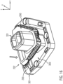
- FIG. 1 schematically illustrates a three dimensional view of the main first connector 100 according to an embodiment of the present invention.
- the main first connector 100 shown in Fig. 1 is a male connector 100, i.e. it comprises male electrical contacts.
- the main male connector 100 comprises a flange 102 from which the main body 101 of the male connector protrudes.
- the main body 101 has a first extremity 110 opposite to the flange 102.
- four projecting elements 130 are formed, which are configured to be inserted into corresponding recesses formed on a corresponding coupling frame in order to lock the male connector, a mating female connector and the frame itself in the assembled state, as will be described in the following. Even if four projecting elements 130 are shown in Fig. 1 , it is clear that any number of projecting elements 130 could be formed, for instance two, three, five or more.
- the main male connector 100 comprises a plurality of pins 120 for mating corresponding electrical terminals or holes of the female connector.
- Two auxiliary first connectors 160A, 160B are formed on the flange 102 of the main male connector 100.
- the two auxiliary first connectors 160A, 160B of Fig. 1 are auxiliary male connectors.
- the two auxiliary first connectors 160A, 160B may also be female connectors.
- any number of auxiliary first connectors may be formed on the main male connector, for instance one, three, four, five or more.
- FIG. 2 schematically illustrates a three dimensional view of the main second connector 200 according to an embodiment of the present invention.
- the main second connector 200 shown in Fig. 2 is a female connector.
- the main female connector 200 comprises a main body 201, which extends from a support element 202 between a first extremity connected to the support element 202 and a second extremity 210.
- the second extremity 210 has a slanted surface 211.
- a plurality of electrical terminals 220 is formed on the main female connector 200 for electrical connection with the corresponding electrical terminals of the main male connector 100.
- Two auxiliary second connectors 260A, 260B are formed on the support element 202 of the main female connector 200.
- the two auxiliary second connectors 260A, 260B of Fig. 2 are auxiliary female connectors. However, it is clear that the two auxiliary second connectors 260A, 260B may also be male connectors. Moreover, even if two auxiliary second connectors 260A, 260B are illustrated in Figure 2 , it is clear that any number of auxiliary second connectors may be formed on the main female connector, for instance one, three, four, five or more.
- the number of auxiliary first connectors is equal to the number of auxiliary second connectors, in order to form corresponding pairs of mating connectors.
- the auxiliary first connectors are male connectors
- the auxiliary second connectors are female connectors and, vice versa
- the auxiliary first connectors are female connectors
- the auxiliary second connectors are male connectors.
- the auxiliary first connectors comprise one or more female connectors and one or more male connectors and, accordingly, the auxiliary second connectors comprise one or more male connectors and one or more female connectors, in order to form corresponding pairs of mating connectors.
- the main female connector 200 further comprises a plurality of alignment holes 250 for fine alignment of the two auxiliary female connectors 260A, 260B with the corresponding auxiliary male connectors 160A, 160B, as will be described in the following. Even if four alignment holes 250 are illustrated in Figure 2 , it is clear that any number of holes may be formed on the female connector, for instance two, three, five or more.
- a pair of alignment holes 250 is mechanically connected to each auxiliary female connector 260A, 260B, so as to form a rigid structure that can slide on guiding means 261A, 261B.
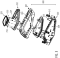
- the support element 202 of the female connector 200 is mechanically connected to a coupling frame or compensation frame 300, which is shown in detail in the exploded view of Figure 3 .
- Figure 3 schematically illustrates an exploded view of the main female connector 200 and of the compensation frame 300, according to the embodiment of the present invention.
- the compensation frame 300 comprises a front component 301 and a rear component 302, which, in the assembled state, accommodate a plurality of elastic means, for instance springs 310. Preferably, four springs 310 are provided in the compensation frame 300.
- the front (301) and the rear (302) components of the compensation frame 300 are secured to one another by means of a plurality of retention elements 320.
- two retention elements 320 are provided for each elastic means 310.
- the retention elements 320 are located next to the elastic means 310.
- the retention elements 320 may be hooking elements or nose elements, as shown in Figure 3 .
- any kind of retention elements may be used to keep the front and rear components 301, 302 of the compensation frame 300 secured together.
- the front component 301 is designed to have an opening 303 for accommodating the support element 202 of the main female connector 200.
- the rear component 302 is designed to have an opening 304 for accommodating an external connector. In this way, the compensation frame 300 may be used for mechanically connecting the main female connector 200 to an external connector.
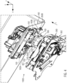
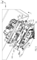
- the main male connector 100 and the main female connector 200 may be advantageously assembled to form a blind connection system 1000 as the ones shown in Figures 4 and 5 .
- Figure 4 schematically illustrates a three-dimensional view of a blind connection system 1000 in a preliminary assembly state
- Figure 5 schematically illustrates a three-dimensional view of a blind connection system 1000 in the assembled state.
- each of the main male connector 100 and the female connector 200 may be connected to other electrical and mechanical components, so as to form a complex electrical and mechanical connection system.
- the main male connector 100 may be inserted into an opening of a container and may be partially covered by a wall 400.
- connection between the main male connector 100 and the main female connector 200 may be advantageously realized by means of an automated machine so as to avoid any intervention of human operators. In this case, it might be necessary to automatically, precisely align the main male connector 100 and the main female connector 200 along the insertion direction z and/or along the directions x and/or y perpendicular to the insertion direction z.
- the particular structure and geometry of the main male and female connectors 100, 200 according to the present invention allow realizing this blind connection and compensating for large misalignments along any directions, for instance misalignments of ⁇ 4 mm.
- This is achieved by designing the first extremity 110 of the main male connector 100 so as to have a slanted surface 111, preferably a slanted surface 111 with a chamfer, in order to guide the displacement of the main female connector 200 and to induce a coaxial alignment of the two main connectors 100 and 200 along the directions x and/or y perpendicular to the insertion direction z.
- the main female connector 200 is designed so as to have a first extremity 210 with a slanted surface 211 having a similar or equal slope with respect to the slanted surface 111 of the second extremity 110 of the main male connector 100.
- the displacement of the main female connector 200 along the x and/or y directions is favored and a coarse coaxial alignment of the main male connector and of the main female connector 200 can be obtained.
- a coarse coaxial alignment of the main male and female connectors 100, 200 along the x and/or y directions indicates that the two main connectors 100, 200 are fully aligned along the x and/or y directions, in order to ensure a stable and secure electrical connection between electrical contacts 120, 220.
- a fine coaxial alignment along the x and/or y directions can be further obtained by inducing a minor displacement of the auxiliary female connectors 260A, 260B, once the alignment pins 150 of the main male connector 100 are inserted into the corresponding alignment holes 250 of the main female connector 200.
- the pins 150 are preferably designed so as to have an end with a slanted surface that induces a minor displacement of the corresponding holes 250 formed on the main female connector 200.
- the holes 250 have a slanted surface having a similar or equal slope to the slanted surface of the pins 150, so as to favor the displacement of the holes 250 and, accordingly, of the auxiliary female connectors 260A, 260B mechanically connected to the holes 250. In this way, fine adjustment between the auxiliary connectors is obtained and the electrical connection between the electrical contacts of the auxiliary male connectors 160A, 160B and the corresponding auxiliary female connectors 260A, 260B is ensured.
- Figure 6 schematically illustrates a two dimensional view of the main male connector 100 and the female connector 200 during the approaching step.
- the main axis A1 of the main male connector 100 and the main axis A2 of the main female connector 200 are not aligned along the x-direction.
- the main axis A1 of the main male connector 100 and the main axis A2 of the main female connector 200 may not be aligned also along the y-direction.
- Figure 6 shows also the axis B1 delimiting the edge of the main male connector 100 and the axis B2 delimiting the edge of the main female connector 200.
- the axes B1 and B2 are parallel in the configuration shown in Figure 6 ; accordingly, there is no misalignment between the two main connectors along the z-direction.
- the two main connectors 100, 200 are misaligned along the z-direction and there is a need to correct this misalignment, as described in the following.
- Figure 6 shows the first slanted surface 111 comprising a chamfered tip; the thickness of the first slanted surface 111 at maximum distance from the tip is indicated as d1 in the figure.
- the second slanted surface 211 comprises a chamfered tip; the thickness of the second slanted surface 211 at maximum distance from the tip is indicated as d2 in Figure 6 .
- the thickness d1 is equal to d2.
- the thicknesses d1 and d2 are comprised in the range between 2 mm and 3 mm, even more preferably equal to 2.5 mm, when misalignments in the order of 4 mm must be compensated for.
- the slanted surface 211 of the main female connector 200 slides along the slanted surface 111 of the main male connector 100 and generates a first force F1 having one or more components perpendicular to the insertion direction z, i.e. one or more components along the x and/or y axes.
- the first force F1 induces a displacement of the main female connector 200 in a direction parallel to the force. For instance, with reference to Fig. 7 , a displacement along the x-axis is induced.
- the displacement of the main female connector 200 may be along the x- and/or y-axes.
- the displacement of the main female connector 200 may be along both the x- and y-axes.
- the first force F1 may hence act on the main female connector 200 so as to tilt it and reduce the angle formed between the main axes A1 and A2 of the main male and female connectors 100 and 200, respectively.
- the displacement of the main female connector 200 can compensate for any misalignments of the main axes A1 and A2 along the x- and/or y-axis, for instance large misalignments, such as misalignments of ⁇ 4 mm along the x- and/or y-axis.
- the main male connector 100 is fixed and remains in the same position.
- the main female connector 200 is coupled to the compensation frame 300; therefore, during displacement of the main female connector 200, the compensation frame 300 is also displaced.
- the displacement of the compensation frame 300 ensures locking with the main male connector 100, as explained in the following.
- the projecting portions 130 formed on the flange 102 of the main male connector 100 are initially partially accommodated into corresponding recesses 330 formed on the compensation frame 300.
- the recesses 330 are displaced as a consequence of the displacement of the compensation frame 300 and the projecting portions 130 are further inserted within the recesses 330.
- the projecting portions 130 lock the main male connector 100 to the compensating frame 300.
- This mechanism hence represents an additional locking feature for the blind connection system 1000.
- the length of the projecting portions 130 and of the recesses 330 must be designed so as to enable displacement of the main female connector 200 and of the compensation frame 300 during the alignment process, for instance they must be designed so as to enable a displacement of 4 mm in case of a large initial misalignment.
- the projecting portions 130 engaged with the recesses 330 are shown in detail in Figure 8 .
- a fine alignment of the pins 150 and the holes 250 and, accordingly, of the auxiliary connectors 160A, 160B, 260A, 260B along the x- and/or y-axes is further obtained by coupling the alignment pins 150 of the main male connector 100 with the corresponding alignment holes 250 of the main female connector 200.
- the alignment pins 150 are formed on the flange 102 of the main male connector 100.
- the alignment holes 250 are mechanically coupled to the auxiliary female connectors 260A, 260B.
- the pins 150 are inserted into the holes 250.
- the pins 150 and the holes 250 are designed so as to have slanted surfaces at their ends, like the main body of the main male and female connectors 100, 200, respectively. Thanks to their slanted surfaces, each pin 150 slides into the corresponding hole 250 and generates a second force F2 having one or more components perpendicular to the insertion direction z, i.e. one or more components along the x and/or y axes.
- the second force F2 induces a displacement of the holes 250 in a direction parallel to the force. For instance, the displacement of the holes 250 may be along the x- and/or y-axes.
- the displacement of the holes 250 may be along both the x- and y-axes.
- the magnitude of the second force F2 is preferably lower than the magnitude of the first force F1 and the displacement induced by the second force F2 during fine alignment is preferably lower than the displacement induced by the first force F1 during coarse alignment. Since the holes 250 are mechanically connected to the auxiliary female connectors 260A, 260B, during displacement of the holes 250, the auxiliary female connectors 260A, 260B are also displaced along the x and/or y direction of the same amount of displacement.
- the auxiliary female connectors 260A, 260B are also aligned with the corresponding auxiliary male connectors 160A, 160B.
- the auxiliary female connectors 260A, 260B are electrically connected to the auxiliary male connectors 160A, 160B.
- Each auxiliary female connector 260A, 260B is displaced along guiding means 261A, 261B formed on the support element 202 of the main female connector 200.
- the support element 202, the main body 201 and the electrical terminals 220 are not displaced during displacement of the auxiliary female connectors 260A, 260B. Accordingly, the electrical connection between the main male and female connectors 100, 200 is not affected by the fine alignment between the auxiliary male and female connectors 160A, 160A, 260A, 260B.
- each auxiliary female connector 260A, 260B is independent from the other auxiliary female connectors 260A, 260B.
- the main male and female connectors 100, 200 and the auxiliary male and female connectors 160A, 160B, 260A, 260B are aligned along the x- and y-axes and the main axes A1 and A2 are coincident.
- the electrical connection between the two connectors 100, 200 is hence obtained, as shown in Figure 10 .
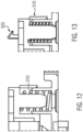
- the compensation frame 300 provided with the elastic means 310 can be used to correct this non-correct positioning, as will be described in the following, with reference to Figures 11-13 .
- Figure 11 schematically illustrates a lateral view of the compensation frame 300, wherein the springs 310 are in the rest configuration.
- Figure 11A schematically illustrates a detail of the spring 310 in the rest configuration.
- the main female connector 200 coupled to the compensation frame 300 is inserted into the main male connector 100.
- the springs 310 are in the rest configuration of Figure 11 .
- the springs 310 may elongate (as schematically illustrate in Fig. 12 ) or compress (as schematically illustrate in Fig.
- one or more springs 310 of the compensation frame 300 may elongate and one or more springs 310 may simultaneously compress in order to induce a tilt of the compensation frame 300 with respect to the z-axis.
- the compensation frame 300 is advantageously designed so that, as a consequence of the adjustment of the position of the compensation frame 300 with respect to the main male connector 100 and the main female connector 200, the electrical connection between the electrical terminals 120 of the male connector and 220 of the female connector is not damaged.
- a blind connection system 1000 may be provided wherein the main male and female connectors 100, 200 are provided with slanted surfaces 111, 211 so as to obtain the blind alignment along the x- and/or y-axes as described above.
- a blind connection system 1000 comprising the compensation frame 300 with elastic means 310 may be provided.
- a blind connection system 1000 may be provided, wherein the main male and female connectors 100, 200 are provided with slanted surfaces 111, 211 and wherein a coupling frame 300 with elastic means 310 is further connected to the main male and female connectors 100, 200.
- a precise and secure connection between the male and female connectors is obtained when the two connectors are aligned along all x-, y- and z-axes.
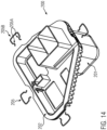
- Figure 14 schematically illustrates an advantageous configuration of the main female connector 200 further comprising centering elastic elements 205 for adjusting the position of the main female connector 200 when assembled with the compensation frame 300.
- each spring clip 205 comprises a wire bent to have a U-shape and having a head 205B and two lateral arms 205A.
- the main female connector 200 is provided with four centering spring clips 205, which are symmetrically placed on the edges of the main female connector 200.
- any other number of centering elastic elements 205 could be provided, for instance two, three, five, six, seven or more.
- the main female connector 200 can be provided with more or less centering spring clips 205, which are not symmetrically placed on the edges of the main female connector 200.
- the centering spring clips 205 are advantageously added to the main female connector 200 to help self-centering of the connector when assembled to the compensation frame 300. Moreover, the centering spring clips 205 help keeping the main female connector 200 fixed and stable in the assembled configuration.
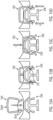
- FIG. 15A to 15D The working principle of the centering spring clips 205, accommodated into the corresponding seats 206, is schematically shown in Figs. 15A to 15D .
- Figure 15A schematically illustrates a first step of use of the centering spring clips 205, wherein a single spring clip 205 is inserted into the corresponding seat 206 along the direction X'.
- Figure 15B schematically illustrates a further step of use, wherein the centering spring clip 205 is retained in the corresponding seat 206 by means of the seat protrusions 207.
- the lateral arms 205A of the spring clip 205 are supported by the seat protrusions 207 and the head 205B of the spring clip 205 remains at a distance d from the seat 206.
- the distance d corresponds to 4 mm
- Figure 15C schematically illustrates a further step of use, wherein an external force f, parallel to the X' direction, is applied to the centering spring clip 205.
- an external force f parallel to the X' direction
- the lateral arms 205A of the centering spring clip 205 slide along the slated surfaces 208 of the seat 206 and the head 205B of the centering spring clip 205 reaches the external surface of the seat 206.
- the centering spring clip 205 remains in the elastic condition without permanent deformation.
- the external force can be modulated by the angle of the slated surfaces 208.
- the external force f can be applied, for instance, as a consequence of a contact of the main female connector 200 with the inner walls of the compensation frame 300, as will be described below.
- Figure 15D schematically illustrates a further step of use of the centering spring clips 205, wherein the external force f is no longer applied and the centering spring clip 205 returns to the rest configuration.
- the lateral arms 205A of the centering spring clip 205 slide backwards along the slanted surfaces 208, as schematically indicated by the arrow A in Fig. 15D , and the head 205B is separated from the external surface of the seat 206.
- the main female connector 200 provided with the centering spring clips 205 is inserted into the opening 303 of the front component 301 of the compensation frame 300 along an insertion direction parallel to the z-axis.
- the head 205B of the spring clip 205 contacts the inner wall 305 of the front component 301 of compensation frame 300.
- the centering spring clip 205 is in a rest state with the head 205B being spaced from the external wall of the seat 206 by a distance d.
- the centering spring clip 205 deforms and compresses during insertion, as a consequence of the external force applied by the slanted inner wall 305 during sliding.
- each centering spring clip 205 applies a counter-force against the inner wall 305 of the front component 301 of the compensation frame 300 and the main second connector 200 self-centers with respect to the compensation frame 300.
- centering spring clips 205 are advantageously symmetrically placed along the perimeter of the main female connector 200, in order to apply symmetric counter-forces and to induce centering of the connector 200 with respect to the compensation frame 300.
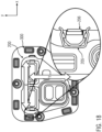
- the centering spring clips 205 can be advantageously employed also during the assembly of the main female connector 200 with the main male connector 100, as explained with reference to Figures 18 and 19 .
- Figure 18 schematically illustrates a configuration of the main female connector 200 with the centering spring clips 205, during assembly with the main male connector 100 (which is not shown for better clarity).
- the main female connector 200 is displaced along the x- and y-directions to compensate for misalignments.
- the centering spring clips 205 are also displaced. For instance, when the main female connector 200 is displaced along the x-direction, each centering spring clip 205 may deform and the head 205B may be pushed against the corresponding seat 206.
- Figure 19 schematically illustrates a configuration of the main female connector 200 with the centering spring clips 205, during disassembly from the main male connector 100 (which is not shown for better clarity).
- main first connector 100 is a male connector and the main second connector 200 is a female connector
- main first connector 100 may also be a female connector
- main second connector 200 may also be a male connector.
- the pair of main first and second connectors 100, 200 form a pair of male and female connectors.
Landscapes
- Engineering & Computer Science (AREA)
- Manufacturing & Machinery (AREA)
- Details Of Connecting Devices For Male And Female Coupling (AREA)
Applications Claiming Priority (2)
| Application Number | Priority Date | Filing Date | Title |
|---|---|---|---|
| IT102022000017349A IT202200017349A1 (it) | 2022-08-17 | 2022-08-17 | Metodo e sistema per connessione ad accoppiamento cieco |
| IT202300011262 | 2023-06-01 |
Publications (1)
| Publication Number | Publication Date |
|---|---|
| EP4376230A1 true EP4376230A1 (fr) | 2024-05-29 |
Family
ID=87557535
Family Applications (1)
| Application Number | Title | Priority Date | Filing Date |
|---|---|---|---|
| EP23191661.0A Pending EP4376230A1 (fr) | 2022-08-17 | 2023-08-16 | Procédé et système de connexion aveugle |
Country Status (4)
| Country | Link |
|---|---|
| US (1) | US20240063577A1 (fr) |
| EP (1) | EP4376230A1 (fr) |
| KR (1) | KR102796858B1 (fr) |
| IL (1) | IL305179A (fr) |
Citations (8)
| Publication number | Priority date | Publication date | Assignee | Title |
|---|---|---|---|---|
| EP0702429A2 (fr) | 1994-09-19 | 1996-03-20 | Molex Incorporated | Système de polarisation pour assemblage de connecteur électrique autocentré |
| EP0753905A1 (fr) * | 1995-07-11 | 1997-01-15 | Societe Anonyme Dite: Carrier Kheops Bac | Connecteur électrique à enfichage automatique |
| EP0794594A2 (fr) * | 1996-03-07 | 1997-09-10 | Honda Giken Kogyo Kabushiki Kaisha | Connecteur et éléments de véhicule ayant un tel connecteur |
| EP2555342A1 (fr) * | 2010-06-04 | 2013-02-06 | Hangzhou Electric Power Bureau | Connecteur de chargement mobile |
| WO2015084246A1 (fr) * | 2013-12-05 | 2015-06-11 | Moduel Ab | Modules électriques |
| DE102019211563A1 (de) | 2018-08-03 | 2020-02-06 | Tyco Electronics France Sas | Leiterplattensteckverbindersystem und verfahren zum verbinden von leiterplatten |
| US10958014B1 (en) * | 2019-09-23 | 2021-03-23 | United States Of America As Represented By The Administrator Of Nasa | Blind mate mechanism |
| DE102020004182A1 (de) * | 2020-07-11 | 2022-01-13 | Kostal Kontakt Systeme Gmbh | Selbstausrichtendes elektrisches Verbindersystem |
Family Cites Families (6)
| Publication number | Priority date | Publication date | Assignee | Title |
|---|---|---|---|---|
| US4853830A (en) * | 1988-03-17 | 1989-08-01 | International Business Machines Corporation | Three stage self alignment structure and method |
| US7172447B2 (en) * | 2004-10-07 | 2007-02-06 | Oceanworks International, Inc. | Subsea gang connector system |
| CN103403978A (zh) * | 2013-01-23 | 2013-11-20 | 华为技术有限公司 | 盲插集成连接器 |
| EP2979464A4 (fr) * | 2013-03-26 | 2016-11-23 | Lachlan Paul Barratt | Filtrage audio avec augmentation de la fréquence d'échantillonnage virtuelle |
| US9948029B1 (en) * | 2015-09-24 | 2018-04-17 | Daplie, Inc. | Peripheral device coupling |
| US12176643B2 (en) * | 2020-09-25 | 2024-12-24 | Intel Corporation | Compression mounted technology (CMT) socket system retention mechanisms designs for shipping reliability risk mitigation |
-
2023
- 2023-08-14 IL IL305179A patent/IL305179A/en unknown
- 2023-08-16 EP EP23191661.0A patent/EP4376230A1/fr active Pending
- 2023-08-16 US US18/450,699 patent/US20240063577A1/en active Pending
- 2023-08-16 KR KR1020230106801A patent/KR102796858B1/ko active Active
Patent Citations (8)
| Publication number | Priority date | Publication date | Assignee | Title |
|---|---|---|---|---|
| EP0702429A2 (fr) | 1994-09-19 | 1996-03-20 | Molex Incorporated | Système de polarisation pour assemblage de connecteur électrique autocentré |
| EP0753905A1 (fr) * | 1995-07-11 | 1997-01-15 | Societe Anonyme Dite: Carrier Kheops Bac | Connecteur électrique à enfichage automatique |
| EP0794594A2 (fr) * | 1996-03-07 | 1997-09-10 | Honda Giken Kogyo Kabushiki Kaisha | Connecteur et éléments de véhicule ayant un tel connecteur |
| EP2555342A1 (fr) * | 2010-06-04 | 2013-02-06 | Hangzhou Electric Power Bureau | Connecteur de chargement mobile |
| WO2015084246A1 (fr) * | 2013-12-05 | 2015-06-11 | Moduel Ab | Modules électriques |
| DE102019211563A1 (de) | 2018-08-03 | 2020-02-06 | Tyco Electronics France Sas | Leiterplattensteckverbindersystem und verfahren zum verbinden von leiterplatten |
| US10958014B1 (en) * | 2019-09-23 | 2021-03-23 | United States Of America As Represented By The Administrator Of Nasa | Blind mate mechanism |
| DE102020004182A1 (de) * | 2020-07-11 | 2022-01-13 | Kostal Kontakt Systeme Gmbh | Selbstausrichtendes elektrisches Verbindersystem |
Also Published As
| Publication number | Publication date |
|---|---|
| IL305179A (en) | 2024-03-01 |
| US20240063577A1 (en) | 2024-02-22 |
| KR102796858B1 (ko) | 2025-04-15 |
| KR20240024756A (ko) | 2024-02-26 |
Similar Documents
| Publication | Publication Date | Title |
|---|---|---|
| US12546951B2 (en) | Single port blindmate for fiber optic connectors | |
| US6422759B1 (en) | Fiber optic connector | |
| US6682230B1 (en) | Optical connector and printed circuit board assembly with movable connection | |
| EP1537629B1 (fr) | Techniques pour connecter un ensemble d'elements connecteurs au moyen d'un dispositif de verrouillage ameliore | |
| EP1411598B1 (fr) | Assemblage de connecteurs, connecteur, montage des connecteurs et méthode pour les assembler | |
| US6773285B2 (en) | Plug connector, consisting of a plug-in jack and a plug part | |
| US6579111B2 (en) | Supporting configuration for a connector | |
| EP0800237B1 (fr) | Structure modulaire pour l'interconnexion de différentes unités et les connecteurs respectifs | |
| JP2002148479A (ja) | 光コネクタのアダプター | |
| EP0872917A2 (fr) | Connecteur pour carte à puce | |
| US9979129B2 (en) | Connector member and connector | |
| EP4376230A1 (fr) | Procédé et système de connexion aveugle | |
| JP2002289298A (ja) | 可動型コネクタ組立体 | |
| WO2006086153A1 (fr) | Systeme de connecteur hermaphrodite pour fibre optique | |
| TW201145707A (en) | Floating connector and system | |
| CN117595044A (zh) | 盲连接的方法和系统 | |
| US20050124187A1 (en) | Methods for controlling contact height | |
| CN119093082A (zh) | 连接座、服务器及计算机设备 | |
| CN111156227B (zh) | 弹性平均关闭狭槽 | |
| CN115441225A (zh) | 具有连接器位置保证件和机械辅助件的电连接器 | |
| KR102764459B1 (ko) | 자동 정렬형 전기 접속안내장치 | |
| US7442088B2 (en) | Methods and apparatus for the prevention of incorrect card insertion | |
| US10276981B2 (en) | Connector member and connector | |
| JP2001351744A (ja) | コネクタの可動構造 | |
| JP2003187909A (ja) | 調芯機構 |
Legal Events
| Date | Code | Title | Description |
|---|---|---|---|
| PUAI | Public reference made under article 153(3) epc to a published international application that has entered the european phase |
Free format text: ORIGINAL CODE: 0009012 |
|
| STAA | Information on the status of an ep patent application or granted ep patent |
Free format text: STATUS: THE APPLICATION HAS BEEN PUBLISHED |
|
| AK | Designated contracting states |
Kind code of ref document: A1 Designated state(s): AL AT BE BG CH CY CZ DE DK EE ES FI FR GB GR HR HU IE IS IT LI LT LU LV MC ME MK MT NL NO PL PT RO RS SE SI SK SM TR |
|
| STAA | Information on the status of an ep patent application or granted ep patent |
Free format text: STATUS: REQUEST FOR EXAMINATION WAS MADE |
|
| 17P | Request for examination filed |
Effective date: 20241112 |
|
| RBV | Designated contracting states (corrected) |
Designated state(s): AL AT BE BG CH CY CZ DE DK EE ES FI FR GB GR HR HU IE IS IT LI LT LU LV MC ME MK MT NL NO PL PT RO RS SE SI SK SM TR |