EP4378024B1 - Procédé de fabrication d'un élément individuel de batterie - Google Patents
Procédé de fabrication d'un élément individuel de batterie Download PDFInfo
- Publication number
- EP4378024B1 EP4378024B1 EP23738639.6A EP23738639A EP4378024B1 EP 4378024 B1 EP4378024 B1 EP 4378024B1 EP 23738639 A EP23738639 A EP 23738639A EP 4378024 B1 EP4378024 B1 EP 4378024B1
- Authority
- EP
- European Patent Office
- Prior art keywords
- stack
- welded
- welding
- cell
- collector tabs
- Prior art date
- Legal status (The legal status is an assumption and is not a legal conclusion. Google has not performed a legal analysis and makes no representation as to the accuracy of the status listed.)
- Active
Links
Images
Classifications
-
- H—ELECTRICITY
- H01—ELECTRIC ELEMENTS
- H01M—PROCESSES OR MEANS, e.g. BATTERIES, FOR THE DIRECT CONVERSION OF CHEMICAL ENERGY INTO ELECTRICAL ENERGY
- H01M50/00—Constructional details or processes of manufacture of the non-active parts of electrochemical cells other than fuel cells, e.g. hybrid cells
- H01M50/50—Current conducting connections for cells or batteries
- H01M50/531—Electrode connections inside a battery casing
- H01M50/536—Electrode connections inside a battery casing characterised by the method of fixing the leads to the electrodes, e.g. by welding
-
- H—ELECTRICITY
- H01—ELECTRIC ELEMENTS
- H01M—PROCESSES OR MEANS, e.g. BATTERIES, FOR THE DIRECT CONVERSION OF CHEMICAL ENERGY INTO ELECTRICAL ENERGY
- H01M50/00—Constructional details or processes of manufacture of the non-active parts of electrochemical cells other than fuel cells, e.g. hybrid cells
- H01M50/10—Primary casings; Jackets or wrappings
- H01M50/147—Lids or covers
- H01M50/166—Lids or covers characterised by the methods of assembling casings with lids
- H01M50/169—Lids or covers characterised by the methods of assembling casings with lids by welding, brazing or soldering
-
- H—ELECTRICITY
- H01—ELECTRIC ELEMENTS
- H01M—PROCESSES OR MEANS, e.g. BATTERIES, FOR THE DIRECT CONVERSION OF CHEMICAL ENERGY INTO ELECTRICAL ENERGY
- H01M50/00—Constructional details or processes of manufacture of the non-active parts of electrochemical cells other than fuel cells, e.g. hybrid cells
- H01M50/50—Current conducting connections for cells or batteries
- H01M50/531—Electrode connections inside a battery casing
- H01M50/533—Electrode connections inside a battery casing characterised by the shape of the leads or tabs
-
- H—ELECTRICITY
- H01—ELECTRIC ELEMENTS
- H01M—PROCESSES OR MEANS, e.g. BATTERIES, FOR THE DIRECT CONVERSION OF CHEMICAL ENERGY INTO ELECTRICAL ENERGY
- H01M50/00—Constructional details or processes of manufacture of the non-active parts of electrochemical cells other than fuel cells, e.g. hybrid cells
- H01M50/50—Current conducting connections for cells or batteries
- H01M50/531—Electrode connections inside a battery casing
- H01M50/538—Connection of several leads or tabs of wound or folded electrode stacks
-
- H—ELECTRICITY
- H01—ELECTRIC ELEMENTS
- H01M—PROCESSES OR MEANS, e.g. BATTERIES, FOR THE DIRECT CONVERSION OF CHEMICAL ENERGY INTO ELECTRICAL ENERGY
- H01M50/00—Constructional details or processes of manufacture of the non-active parts of electrochemical cells other than fuel cells, e.g. hybrid cells
- H01M50/50—Current conducting connections for cells or batteries
- H01M50/531—Electrode connections inside a battery casing
- H01M50/54—Connection of several leads or tabs of plate-like electrode stacks, e.g. electrode pole straps or bridges
-
- H—ELECTRICITY
- H01—ELECTRIC ELEMENTS
- H01M—PROCESSES OR MEANS, e.g. BATTERIES, FOR THE DIRECT CONVERSION OF CHEMICAL ENERGY INTO ELECTRICAL ENERGY
- H01M50/00—Constructional details or processes of manufacture of the non-active parts of electrochemical cells other than fuel cells, e.g. hybrid cells
- H01M50/50—Current conducting connections for cells or batteries
- H01M50/543—Terminals
- H01M50/564—Terminals characterised by their manufacturing process
- H01M50/566—Terminals characterised by their manufacturing process by welding, soldering or brazing
-
- B—PERFORMING OPERATIONS; TRANSPORTING
- B23—MACHINE TOOLS; METAL-WORKING NOT OTHERWISE PROVIDED FOR
- B23K—SOLDERING OR UNSOLDERING; WELDING; CLADDING OR PLATING BY SOLDERING OR WELDING; CUTTING BY APPLYING HEAT LOCALLY, e.g. FLAME CUTTING; WORKING BY LASER BEAM
- B23K20/00—Non-electric welding by applying impact or other pressure, with or without the application of heat, e.g. cladding or plating
- B23K20/10—Non-electric welding by applying impact or other pressure, with or without the application of heat, e.g. cladding or plating making use of vibrations, e.g. ultrasonic welding
-
- B—PERFORMING OPERATIONS; TRANSPORTING
- B23—MACHINE TOOLS; METAL-WORKING NOT OTHERWISE PROVIDED FOR
- B23K—SOLDERING OR UNSOLDERING; WELDING; CLADDING OR PLATING BY SOLDERING OR WELDING; CUTTING BY APPLYING HEAT LOCALLY, e.g. FLAME CUTTING; WORKING BY LASER BEAM
- B23K2101/00—Articles made by soldering, welding or cutting
- B23K2101/36—Electric or electronic devices
-
- Y—GENERAL TAGGING OF NEW TECHNOLOGICAL DEVELOPMENTS; GENERAL TAGGING OF CROSS-SECTIONAL TECHNOLOGIES SPANNING OVER SEVERAL SECTIONS OF THE IPC; TECHNICAL SUBJECTS COVERED BY FORMER USPC CROSS-REFERENCE ART COLLECTIONS [XRACs] AND DIGESTS
- Y02—TECHNOLOGIES OR APPLICATIONS FOR MITIGATION OR ADAPTATION AGAINST CLIMATE CHANGE
- Y02E—REDUCTION OF GREENHOUSE GAS [GHG] EMISSIONS, RELATED TO ENERGY GENERATION, TRANSMISSION OR DISTRIBUTION
- Y02E60/00—Enabling technologies; Technologies with a potential or indirect contribution to GHG emissions mitigation
- Y02E60/10—Energy storage using batteries
-
- Y—GENERAL TAGGING OF NEW TECHNOLOGICAL DEVELOPMENTS; GENERAL TAGGING OF CROSS-SECTIONAL TECHNOLOGIES SPANNING OVER SEVERAL SECTIONS OF THE IPC; TECHNICAL SUBJECTS COVERED BY FORMER USPC CROSS-REFERENCE ART COLLECTIONS [XRACs] AND DIGESTS
- Y02—TECHNOLOGIES OR APPLICATIONS FOR MITIGATION OR ADAPTATION AGAINST CLIMATE CHANGE
- Y02P—CLIMATE CHANGE MITIGATION TECHNOLOGIES IN THE PRODUCTION OR PROCESSING OF GOODS
- Y02P70/00—Climate change mitigation technologies in the production process for final industrial or consumer products
- Y02P70/50—Manufacturing or production processes characterised by the final manufactured product
Definitions
- the invention relates to a method for manufacturing a single battery cell according to the type defined in the preamble of claim 1
- Individual battery cells for example in lithium-ion technology, are fundamentally known from the state of the art. They essentially consist of a housing and electrochemically active materials arranged in this housing. Typically, this is a stack or possibly a coil of cathodes, anodes and separators, which are placed in the housing and soaked with electrolyte. Finally, the housing is closed.
- the electrodes are typically contacted via conductor tabs that protrude above the stack or coil, with the conductor tabs of the cathode typically protruding on one side and the conductor tabs of the anode on the other.
- the conductor tabs of the anodes can be welded together and those of the cathode pressed against a metallically conductive housing or something similar. Of course, this can also be done the other way around, or both electrodes can be welded accordingly.
- an electrode arrangement for a battery cell is known.
- the conductor tabs of the individual electrodes are wound together with a conductor of the individual battery cell and are connected, e.g. welded, to an anode conductor or cathode conductor for all corresponding electrodes within the individual battery cell. This can then be led out of a housing in an insulated manner, for example.
- the WO 2010/030606 A2 describes an electrochemical cell with at least one electrode.
- the end of each individual electrode foil that protrudes above the active material is wound up to facilitate contacting of all the same-polar electrodes of the individual battery cell.
- the object of the present invention is to provide a method for manufacturing a battery cell which further simplifies the structure known from the general prior art and yet ensures safe and reliable electrical contacting of the conductor lugs.
- the method according to the invention provides that the conductor lugs are welded, as is known from the prior art. According to the invention, they are compacted and first tacked on their side facing the stack or coil by this welding, which according to a very advantageous embodiment can be designed as ultrasonic welding, in order to prevent their position within the stack or coil is changed and individual electrodes or separators are pulled out of the stack or coil during production.
- the conductor lugs stapled in this way using ultrasonic welding are then gripped by a welding electrode at the end facing away from the stack or coil and wound around this welding electrode in the direction of the stack or coil. Finally, a cell cover of the individual battery cell is welded to the wound conductor lugs.
- the conductor lugs are wound up in the direction of the stack on a welding electrode located inside this coil.
- the structure can then be supplemented directly by the cell cover, i.e. without an intermediate current collector, by welding this cell cover to the rolled-up or wound conductor foils. These then form a coil welded to the cell cover, resulting in a mechanically stable structure that only partially transfers the heat generated during welding to the stack or coil. In particular, a large part of the heat is dissipated by the welding electrode.
- the conductor foils are gripped by means of a groove in the welding electrode.
- a groove can be provided, for example, in a square or round welding electrode. This is positioned on the stack of stapled conductor tabs in such a way that the end facing away from the stack or coil, which was compacted during or after stapling, comes to rest in this groove. By turning the welding electrode, this compacted stack of conductor foils is then wound around this welding electrode.
- the welding electrode is then removed from the wound conductor foils after the wound conductor foils have been welded onto the cell cover, so that a hollow roll remains which is very stable in itself due to the multi-layer structure, the individual layers of which are welded to one another and to the cell cover in a line along the central axis of the welding electrode on the side facing the cell cover.
- This very stable structure consisting of cell cover and stack or coil can then be handled easily and efficiently and inserted into a housing, after which the cell cover is welded to the housing, preferably by laser welding.
- the wound arrester foils can also be welded onto the cell cover or the cell cover onto the wound arrester foils using ultrasonic welding. Only the welding of the cover onto the housing can be implemented more efficiently, preferably using laser welding.
- Another very advantageous embodiment of the method for producing the individual battery cell according to the invention provides that the conductor foils are stapled in the stacking direction or transversely to the winding direction at approximately the middle height.
- the conductor foils are therefore not collected on one side of the stack and compacted and welded there, as is largely common today, but rather they are brought together in the middle in order to staple them together as close as possible to the cell stack, with the individual conductor foils having to travel as little distance as possible to the weld seam.
- a single battery cell produced according to the method according to the invention now provides a stack or coil of cathodes, anodes and separators, which is arranged in a cell housing closed with a cell cover.
- the conductor lugs of at least one of the electrodes protrude beyond the stack or coil and are rolled up in this area and welded to the cell cover.
- the cell cover can in turn be welded to the housing.
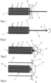
- a section of a stack 1 can be seen.
- This stack 1 consists of different electrodes 2, 3, i.e. the anodes and the cathodes. Separators 4 are arranged between them.
- the cathodes are supported on an aluminum foil, which is shown here with a thick solid black line.
- the ends of these cathodes 2 protrude laterally over the stack 1 as conductor lugs 5 transversely to the stacking direction S. They are combined in this area, whereby only five individual cathodes 2 are shown in the figure in order to simplify the illustration accordingly.
- the conductor lugs 5 are combined in the middle in relation to the height of the stack 1 in the stacking direction S and are compacted in the area designated 5'.
- the end of the compacted conductor lugs 5' facing away from the stack 1 is now gripped by a welding electrode 7, which is designed, for example, as a rod-shaped electrode with a groove 8, by inserting the compacted conductor lugs 5' into this groove.
- the welding electrode 7 is then inserted according to the arrow in Figure 2 wound in the direction of the stack 1, so that a roll 5" is created from several spiral layers of the compacted conductor lugs 5'.
- This roll 5" with the welding electrode 7 arranged therein is then brought into contact with a cell cover 9 and welded to it through the material of this cell cover 9.
- This process can also be carried out as ultrasonic welding, which is why the symbolic representation of the welding is again provided with the reference number 6.
- the wound conductor lugs, which are designated here with 5" after winding into the roll form a very compact Structure which can be easily welded to the cell cover 9 efficiently and reliably.
- the welding electrode 7 is then pulled out sideways and a very robust structure is created from stack 1 and cell cover 9, which can then be placed, for example, in a housing already filled with electrolyte or, after soaking the stack 1, in a housing 10 such as that shown in the illustration of the Figure 4 can be seen.
- the structure is also shown purely schematically here, typically the cell stack will of course use more space within the housing.
- the cell cover 9 can then be welded to the housing 10, for example by laser welding, which is indicated here by the two triangles 11.
- the described method and the single battery cell 12 obtainable by this method can be used for both round and prismatic housings 9.
- it is suitable for the electrical contact of a stack 1 with the cell cover and is therefore preferably used for a structure with a prismatic housing 10.
Landscapes
- Chemical & Material Sciences (AREA)
- Chemical Kinetics & Catalysis (AREA)
- Electrochemistry (AREA)
- General Chemical & Material Sciences (AREA)
- Engineering & Computer Science (AREA)
- Manufacturing & Machinery (AREA)
- Connection Of Batteries Or Terminals (AREA)
- Secondary Cells (AREA)
- Sealing Battery Cases Or Jackets (AREA)
Claims (8)
- Procédé permettant de fabriquer un élément individuel de batterie (12) comportant un empilement (1) ou un enroulement d'électrodes (2, 3) et de séparateurs (4), dans lequel au moins l'une des électrodes (2, 3) présente des pattes de parafoudre (5) dépassant latéralement dans une direction au-delà de l'empilement (1) ou de l'enroulement, lesquelles pattes sont soudées entre elles, caractérisé en ce que
les pattes de parafoudre (5) sont compactées et agrafées par soudage sur leur côté tourné vers l'empilement (1) ou l'enroulement, après quoi les pattes de parafoudre (5') compactées et soudées sont saisies par une électrode de soudage (7) sur leur côté opposé à l'empilement (1) ou à l'enroulement et enroulées autour de l'électrode de soudage (7) en direction de l'empilement (1) ou de l'enroulement, et après quoi un couvercle d'élément (9) de l'élément individuel de batterie (12) est soudé aux pattes de parafoudre (5') enroulées. - Procédé selon la revendication 1,
caractérisé en ce que
les pattes de parafoudre (5') compactées et soudées sont saisies à l'aide d'une rainure (8) dans l'électrode de soudage (7). - Procédé selon la revendication 1 ou 2,
caractérisé en ce que
l'électrode de soudage (7) est retirée des pattes de parafoudre (5") enroulées après le soudage des pattes de parafoudre (5") enroulées avec le couvercle d'élément (9). - Procédé selon la revendication 1, 2 ou 3,
caractérisé en ce que
l'empilement (1) ou l'enroulement comportant le couvercle d'élément (9) soudé est introduit dans un boîtier (10), après quoi le couvercle d'élément (9) est soudé au boîtier (10). - Procédé selon la revendication 4,
caractérisé en ce
qu'on utilise un soudage au laser pour le soudage du couvercle d'élément (9) au boîtier (10). - Procédé selon l'une des revendications 1 à 5,
caractérisé en ce que
les pattes de parafoudre (5) sont soudées pour l'agrafage à l'aide du soudage par ultrasons. - Procédé selon l'une des revendications 1 à 6,
caractérisé en ce que
les pattes de parafoudre (5") enroulées sont soudées au couvercle d'élément (9) à l'aide du soudage par ultrasons. - Procédé selon l'une des revendications 1 à 7,
caractérisé en ce que
l'agrafage des pattes de parafoudre (5) s'effectue dans le sens d'empilement (S) ou transversalement au sens d'enroulement à une hauteur approximativement centrale.
Applications Claiming Priority (2)
| Application Number | Priority Date | Filing Date | Title |
|---|---|---|---|
| DE102022002419.5A DE102022002419B3 (de) | 2022-07-04 | 2022-07-04 | Verfahren zum Fertigen einer Batterieeinzelzelle |
| PCT/EP2023/067890 WO2024008555A1 (fr) | 2022-07-04 | 2023-06-29 | Procédé de fabrication d'un élément individuel de batterie |
Publications (3)
| Publication Number | Publication Date |
|---|---|
| EP4378024A1 EP4378024A1 (fr) | 2024-06-05 |
| EP4378024C0 EP4378024C0 (fr) | 2025-02-12 |
| EP4378024B1 true EP4378024B1 (fr) | 2025-02-12 |
Family
ID=87157986
Family Applications (1)
| Application Number | Title | Priority Date | Filing Date |
|---|---|---|---|
| EP23738639.6A Active EP4378024B1 (fr) | 2022-07-04 | 2023-06-29 | Procédé de fabrication d'un élément individuel de batterie |
Country Status (7)
| Country | Link |
|---|---|
| US (1) | US20250125502A1 (fr) |
| EP (1) | EP4378024B1 (fr) |
| JP (1) | JP7742937B2 (fr) |
| KR (1) | KR20240039063A (fr) |
| CN (1) | CN118020210A (fr) |
| DE (1) | DE102022002419B3 (fr) |
| WO (1) | WO2024008555A1 (fr) |
Family Cites Families (5)
| Publication number | Priority date | Publication date | Assignee | Title |
|---|---|---|---|---|
| CN102197530B (zh) | 2008-09-09 | 2015-10-21 | 江森自控帅福得先进能源动力系统有限责任公司 | 具有折叠电极的电化学电池单元 |
| US20110206976A1 (en) | 2010-02-19 | 2011-08-25 | Kyung-Mo Yoo | Electrode assembly and secondary battery using the same |
| JP5649996B2 (ja) * | 2010-07-14 | 2015-01-07 | 三洋電機株式会社 | 角形密閉二次電池及びその製造方法 |
| JP6293501B2 (ja) * | 2014-01-29 | 2018-03-14 | 株式会社東芝 | 二次電池、及び二次電池の製造方法 |
| DE102015209719B4 (de) | 2015-05-27 | 2019-06-19 | Thyssenkrupp Ag | Niederhaltevorrichtung, Schweißvorrichtung und Verfahren zum Ultraschallschweißen |
-
2022
- 2022-07-04 DE DE102022002419.5A patent/DE102022002419B3/de active Active
-
2023
- 2023-06-29 WO PCT/EP2023/067890 patent/WO2024008555A1/fr not_active Ceased
- 2023-06-29 CN CN202380013724.7A patent/CN118020210A/zh active Pending
- 2023-06-29 EP EP23738639.6A patent/EP4378024B1/fr active Active
- 2023-06-29 KR KR1020247008449A patent/KR20240039063A/ko not_active Ceased
- 2023-06-29 JP JP2024526681A patent/JP7742937B2/ja active Active
- 2023-06-29 US US18/694,316 patent/US20250125502A1/en active Pending
Also Published As
| Publication number | Publication date |
|---|---|
| EP4378024A1 (fr) | 2024-06-05 |
| EP4378024C0 (fr) | 2025-02-12 |
| CN118020210A (zh) | 2024-05-10 |
| WO2024008555A1 (fr) | 2024-01-11 |
| KR20240039063A (ko) | 2024-03-26 |
| JP7742937B2 (ja) | 2025-09-22 |
| US20250125502A1 (en) | 2025-04-17 |
| DE102022002419B3 (de) | 2023-11-23 |
| JP2024538342A (ja) | 2024-10-18 |
Similar Documents
| Publication | Publication Date | Title |
|---|---|---|
| EP2389697B1 (fr) | Cellule de stockage d'énergie électrochimique | |
| EP2404338A2 (fr) | Cellule d'accumulation d'énergie électrique et bloc de cellules | |
| DE112011100279T5 (de) | Batteriezellen- Modul für eine modulare Batterie mit einem verschachtelt angeordnetem Trennelement | |
| DE10020413B4 (de) | Sekundärbatterie mit nichtwässrigem Elektrolyten | |
| DE102009024513A1 (de) | Batteriezellenverbinder | |
| DE202009012647U1 (de) | Batteriezellenverbinder | |
| EP4320670B1 (fr) | Unité de connexion pour la mise en contact électrique d'au moins deux cellules de stockage, unité de stockage et procédé | |
| EP2460206B1 (fr) | Batterie comprenant un empilement d'éléments de batterie unitaires bipolaires | |
| EP3618147A1 (fr) | Élément de batterie et procédé de fabrication d'un élément de batterie | |
| EP4378024B1 (fr) | Procédé de fabrication d'un élément individuel de batterie | |
| DE102008059963B4 (de) | Einzelzelle für eine Batterie und Verfahren zu deren Herstellung | |
| EP2243179B1 (fr) | Procédé de fabrication d'une cellule individuelle pour batterie | |
| DE10237293A1 (de) | Elektroden-Ableiter-Abschnitt und Verfahren zur Kontaktierung von mehreren Elektroden | |
| WO2016116322A1 (fr) | Enroulement de cellule pour accumulateur à ions lithium | |
| EP3008766B1 (fr) | Accumulateur et procédé permettant de fabriquer un accumulateur | |
| DE102022211098A1 (de) | Batteriezelle sowie Verfahren zu deren Herstellung | |
| DE102022105982A1 (de) | Verfahren zur Montage einer Batterie | |
| DE102023127839B4 (de) | Batteriezelle für eine Hochvoltbatterie sowie Verfahren zur Herstellung einer Batteriezelle | |
| EP4675800A1 (fr) | Module de batterie, batterie et véhicule | |
| WO2019086338A1 (fr) | Technique de liaison pour des contacts de pôles de batteries | |
| DE102023123635A1 (de) | Batterieeinzelzelle mit wenigstens einem Stapel von Elektroden und Separatoren | |
| DE102011109237A1 (de) | Batteriezelle | |
| DE102020004922A1 (de) | Batteriemodul | |
| DE102022001768A1 (de) | Verfahren zur Herstellung eines Elektrodenwickels für eine Batteriezelle | |
| WO2025077964A1 (fr) | Élément de batterie et véhicule comprenant l'élément de batterie |
Legal Events
| Date | Code | Title | Description |
|---|---|---|---|
| STAA | Information on the status of an ep patent application or granted ep patent |
Free format text: STATUS: UNKNOWN |
|
| STAA | Information on the status of an ep patent application or granted ep patent |
Free format text: STATUS: THE INTERNATIONAL PUBLICATION HAS BEEN MADE |
|
| PUAI | Public reference made under article 153(3) epc to a published international application that has entered the european phase |
Free format text: ORIGINAL CODE: 0009012 |
|
| STAA | Information on the status of an ep patent application or granted ep patent |
Free format text: STATUS: REQUEST FOR EXAMINATION WAS MADE |
|
| 17P | Request for examination filed |
Effective date: 20240228 |
|
| AK | Designated contracting states |
Kind code of ref document: A1 Designated state(s): AL AT BE BG CH CY CZ DE DK EE ES FI FR GB GR HR HU IE IS IT LI LT LU LV MC ME MK MT NL NO PL PT RO RS SE SI SK SM TR |
|
| GRAP | Despatch of communication of intention to grant a patent |
Free format text: ORIGINAL CODE: EPIDOSNIGR1 |
|
| STAA | Information on the status of an ep patent application or granted ep patent |
Free format text: STATUS: GRANT OF PATENT IS INTENDED |
|
| INTG | Intention to grant announced |
Effective date: 20240812 |
|
| GRAS | Grant fee paid |
Free format text: ORIGINAL CODE: EPIDOSNIGR3 |
|
| GRAA | (expected) grant |
Free format text: ORIGINAL CODE: 0009210 |
|
| STAA | Information on the status of an ep patent application or granted ep patent |
Free format text: STATUS: THE PATENT HAS BEEN GRANTED |
|
| AK | Designated contracting states |
Kind code of ref document: B1 Designated state(s): AL AT BE BG CH CY CZ DE DK EE ES FI FR GB GR HR HU IE IS IT LI LT LU LV MC ME MK MT NL NO PL PT RO RS SE SI SK SM TR |
|
| DAV | Request for validation of the european patent (deleted) | ||
| DAX | Request for extension of the european patent (deleted) | ||
| REG | Reference to a national code |
Ref country code: GB Ref legal event code: FG4D Free format text: NOT ENGLISH |
|
| REG | Reference to a national code |
Ref country code: CH Ref legal event code: EP |
|
| REG | Reference to a national code |
Ref country code: DE Ref legal event code: R096 Ref document number: 502023000557 Country of ref document: DE |
|
| REG | Reference to a national code |
Ref country code: IE Ref legal event code: FG4D Free format text: LANGUAGE OF EP DOCUMENT: GERMAN |
|
| U01 | Request for unitary effect filed |
Effective date: 20250303 |
|
| U07 | Unitary effect registered |
Designated state(s): AT BE BG DE DK EE FI FR IT LT LU LV MT NL PT RO SE SI Effective date: 20250311 |
|
| PG25 | Lapsed in a contracting state [announced via postgrant information from national office to epo] |
Ref country code: RS Free format text: LAPSE BECAUSE OF FAILURE TO SUBMIT A TRANSLATION OF THE DESCRIPTION OR TO PAY THE FEE WITHIN THE PRESCRIBED TIME-LIMIT Effective date: 20250512 |
|
| PG25 | Lapsed in a contracting state [announced via postgrant information from national office to epo] |
Ref country code: PL Free format text: LAPSE BECAUSE OF FAILURE TO SUBMIT A TRANSLATION OF THE DESCRIPTION OR TO PAY THE FEE WITHIN THE PRESCRIBED TIME-LIMIT Effective date: 20250212 |
|
| PG25 | Lapsed in a contracting state [announced via postgrant information from national office to epo] |
Ref country code: ES Free format text: LAPSE BECAUSE OF FAILURE TO SUBMIT A TRANSLATION OF THE DESCRIPTION OR TO PAY THE FEE WITHIN THE PRESCRIBED TIME-LIMIT Effective date: 20250212 |
|
| PG25 | Lapsed in a contracting state [announced via postgrant information from national office to epo] |
Ref country code: IS Free format text: LAPSE BECAUSE OF FAILURE TO SUBMIT A TRANSLATION OF THE DESCRIPTION OR TO PAY THE FEE WITHIN THE PRESCRIBED TIME-LIMIT Effective date: 20250612 Ref country code: NO Free format text: LAPSE BECAUSE OF FAILURE TO SUBMIT A TRANSLATION OF THE DESCRIPTION OR TO PAY THE FEE WITHIN THE PRESCRIBED TIME-LIMIT Effective date: 20250512 |
|
| PG25 | Lapsed in a contracting state [announced via postgrant information from national office to epo] |
Ref country code: HR Free format text: LAPSE BECAUSE OF FAILURE TO SUBMIT A TRANSLATION OF THE DESCRIPTION OR TO PAY THE FEE WITHIN THE PRESCRIBED TIME-LIMIT Effective date: 20250212 |
|
| PG25 | Lapsed in a contracting state [announced via postgrant information from national office to epo] |
Ref country code: GR Free format text: LAPSE BECAUSE OF FAILURE TO SUBMIT A TRANSLATION OF THE DESCRIPTION OR TO PAY THE FEE WITHIN THE PRESCRIBED TIME-LIMIT Effective date: 20250513 |
|
| U20 | Renewal fee for the european patent with unitary effect paid |
Year of fee payment: 3 Effective date: 20250624 |
|
| PG25 | Lapsed in a contracting state [announced via postgrant information from national office to epo] |
Ref country code: SM Free format text: LAPSE BECAUSE OF FAILURE TO SUBMIT A TRANSLATION OF THE DESCRIPTION OR TO PAY THE FEE WITHIN THE PRESCRIBED TIME-LIMIT Effective date: 20250212 |
|
| PG25 | Lapsed in a contracting state [announced via postgrant information from national office to epo] |
Ref country code: CZ Free format text: LAPSE BECAUSE OF FAILURE TO SUBMIT A TRANSLATION OF THE DESCRIPTION OR TO PAY THE FEE WITHIN THE PRESCRIBED TIME-LIMIT Effective date: 20250212 |
|
| PG25 | Lapsed in a contracting state [announced via postgrant information from national office to epo] |
Ref country code: SK Free format text: LAPSE BECAUSE OF FAILURE TO SUBMIT A TRANSLATION OF THE DESCRIPTION OR TO PAY THE FEE WITHIN THE PRESCRIBED TIME-LIMIT Effective date: 20250212 |
|
| PLBE | No opposition filed within time limit |
Free format text: ORIGINAL CODE: 0009261 |
|
| STAA | Information on the status of an ep patent application or granted ep patent |
Free format text: STATUS: NO OPPOSITION FILED WITHIN TIME LIMIT |
|
| 26N | No opposition filed |
Effective date: 20251113 |
|
| PG25 | Lapsed in a contracting state [announced via postgrant information from national office to epo] |
Ref country code: MC Free format text: LAPSE BECAUSE OF FAILURE TO SUBMIT A TRANSLATION OF THE DESCRIPTION OR TO PAY THE FEE WITHIN THE PRESCRIBED TIME-LIMIT Effective date: 20250212 |