EP4378367A1 - Reiniger - Google Patents
Reiniger Download PDFInfo
- Publication number
- EP4378367A1 EP4378367A1 EP22849872.1A EP22849872A EP4378367A1 EP 4378367 A1 EP4378367 A1 EP 4378367A1 EP 22849872 A EP22849872 A EP 22849872A EP 4378367 A1 EP4378367 A1 EP 4378367A1
- Authority
- EP
- European Patent Office
- Prior art keywords
- cleaning module
- disposed
- heater
- cleaner
- air
- Prior art date
- Legal status (The legal status is an assumption and is not a legal conclusion. Google has not performed a legal analysis and makes no representation as to the accuracy of the status listed.)
- Pending
Links
Images








Classifications
-
- A—HUMAN NECESSITIES
- A47—FURNITURE; DOMESTIC ARTICLES OR APPLIANCES; COFFEE MILLS; SPICE MILLS; SUCTION CLEANERS IN GENERAL
- A47L—DOMESTIC WASHING OR CLEANING; SUCTION CLEANERS IN GENERAL
- A47L9/00—Details or accessories of suction cleaners, e.g. mechanical means for controlling the suction or for effecting pulsating action; Storing devices specially adapted to suction cleaners or parts thereof; Carrying-vehicles specially adapted for suction cleaners
- A47L9/28—Installation of the electric equipment, e.g. adaptation or attachment to the suction cleaner; Controlling suction cleaners by electric means
- A47L9/30—Arrangement of illuminating devices
-
- A—HUMAN NECESSITIES
- A47—FURNITURE; DOMESTIC ARTICLES OR APPLIANCES; COFFEE MILLS; SPICE MILLS; SUCTION CLEANERS IN GENERAL
- A47L—DOMESTIC WASHING OR CLEANING; SUCTION CLEANERS IN GENERAL
- A47L11/00—Machines for cleaning floors, carpets, furniture, walls, or wall coverings
- A47L11/29—Floor-scrubbing machines characterised by means for taking-up dirty liquid
- A47L11/30—Floor-scrubbing machines characterised by means for taking-up dirty liquid by suction
- A47L11/302—Floor-scrubbing machines characterised by means for taking-up dirty liquid by suction having rotary tools
- A47L11/305—Floor-scrubbing machines characterised by means for taking-up dirty liquid by suction having rotary tools the tools being disc brushes
-
- A—HUMAN NECESSITIES
- A47—FURNITURE; DOMESTIC ARTICLES OR APPLIANCES; COFFEE MILLS; SPICE MILLS; SUCTION CLEANERS IN GENERAL
- A47L—DOMESTIC WASHING OR CLEANING; SUCTION CLEANERS IN GENERAL
- A47L11/00—Machines for cleaning floors, carpets, furniture, walls, or wall coverings
- A47L11/34—Machines for treating carpets in position by liquid, foam, or vapour, e.g. by steam
-
- A—HUMAN NECESSITIES
- A47—FURNITURE; DOMESTIC ARTICLES OR APPLIANCES; COFFEE MILLS; SPICE MILLS; SUCTION CLEANERS IN GENERAL
- A47L—DOMESTIC WASHING OR CLEANING; SUCTION CLEANERS IN GENERAL
- A47L11/00—Machines for cleaning floors, carpets, furniture, walls, or wall coverings
- A47L11/40—Parts or details of machines not provided for in groups A47L11/02 - A47L11/38, or not restricted to one of these groups, e.g. handles, arrangements of switches, skirts, buffers, levers
-
- A—HUMAN NECESSITIES
- A47—FURNITURE; DOMESTIC ARTICLES OR APPLIANCES; COFFEE MILLS; SPICE MILLS; SUCTION CLEANERS IN GENERAL
- A47L—DOMESTIC WASHING OR CLEANING; SUCTION CLEANERS IN GENERAL
- A47L11/00—Machines for cleaning floors, carpets, furniture, walls, or wall coverings
- A47L11/40—Parts or details of machines not provided for in groups A47L11/02 - A47L11/38, or not restricted to one of these groups, e.g. handles, arrangements of switches, skirts, buffers, levers
- A47L11/4002—Installations of electric equipment
-
- A—HUMAN NECESSITIES
- A47—FURNITURE; DOMESTIC ARTICLES OR APPLIANCES; COFFEE MILLS; SPICE MILLS; SUCTION CLEANERS IN GENERAL
- A47L—DOMESTIC WASHING OR CLEANING; SUCTION CLEANERS IN GENERAL
- A47L11/00—Machines for cleaning floors, carpets, furniture, walls, or wall coverings
- A47L11/40—Parts or details of machines not provided for in groups A47L11/02 - A47L11/38, or not restricted to one of these groups, e.g. handles, arrangements of switches, skirts, buffers, levers
- A47L11/4036—Parts or details of the surface treating tools
- A47L11/4038—Disk shaped surface treating tools
-
- A—HUMAN NECESSITIES
- A47—FURNITURE; DOMESTIC ARTICLES OR APPLIANCES; COFFEE MILLS; SPICE MILLS; SUCTION CLEANERS IN GENERAL
- A47L—DOMESTIC WASHING OR CLEANING; SUCTION CLEANERS IN GENERAL
- A47L11/00—Machines for cleaning floors, carpets, furniture, walls, or wall coverings
- A47L11/40—Parts or details of machines not provided for in groups A47L11/02 - A47L11/38, or not restricted to one of these groups, e.g. handles, arrangements of switches, skirts, buffers, levers
- A47L11/4063—Driving means; Transmission means therefor
- A47L11/4069—Driving or transmission means for the cleaning tools
-
- A—HUMAN NECESSITIES
- A47—FURNITURE; DOMESTIC ARTICLES OR APPLIANCES; COFFEE MILLS; SPICE MILLS; SUCTION CLEANERS IN GENERAL
- A47L—DOMESTIC WASHING OR CLEANING; SUCTION CLEANERS IN GENERAL
- A47L11/00—Machines for cleaning floors, carpets, furniture, walls, or wall coverings
- A47L11/40—Parts or details of machines not provided for in groups A47L11/02 - A47L11/38, or not restricted to one of these groups, e.g. handles, arrangements of switches, skirts, buffers, levers
- A47L11/4077—Skirts or splash guards
-
- A—HUMAN NECESSITIES
- A47—FURNITURE; DOMESTIC ARTICLES OR APPLIANCES; COFFEE MILLS; SPICE MILLS; SUCTION CLEANERS IN GENERAL
- A47L—DOMESTIC WASHING OR CLEANING; SUCTION CLEANERS IN GENERAL
- A47L11/00—Machines for cleaning floors, carpets, furniture, walls, or wall coverings
- A47L11/40—Parts or details of machines not provided for in groups A47L11/02 - A47L11/38, or not restricted to one of these groups, e.g. handles, arrangements of switches, skirts, buffers, levers
- A47L11/408—Means for supplying cleaning or surface treating agents
- A47L11/4086—Arrangements for steam generation
-
- A—HUMAN NECESSITIES
- A47—FURNITURE; DOMESTIC ARTICLES OR APPLIANCES; COFFEE MILLS; SPICE MILLS; SUCTION CLEANERS IN GENERAL
- A47L—DOMESTIC WASHING OR CLEANING; SUCTION CLEANERS IN GENERAL
- A47L13/00—Implements for cleaning floors, carpets, furniture, walls, or wall coverings
- A47L13/10—Scrubbing; Scouring; Cleaning; Polishing
- A47L13/20—Mops
- A47L13/22—Mops with liquid-feeding devices
- A47L13/225—Steam mops
-
- A—HUMAN NECESSITIES
- A47—FURNITURE; DOMESTIC ARTICLES OR APPLIANCES; COFFEE MILLS; SPICE MILLS; SUCTION CLEANERS IN GENERAL
- A47L—DOMESTIC WASHING OR CLEANING; SUCTION CLEANERS IN GENERAL
- A47L9/00—Details or accessories of suction cleaners, e.g. mechanical means for controlling the suction or for effecting pulsating action; Storing devices specially adapted to suction cleaners or parts thereof; Carrying-vehicles specially adapted for suction cleaners
- A47L9/28—Installation of the electric equipment, e.g. adaptation or attachment to the suction cleaner; Controlling suction cleaners by electric means
Definitions
- the present disclosure relates to a cleaner and more particularly to a portable vacuum cleaner of which a cleaning module can be attached and detached.
- a cleaner is a home appliance which sucks tiny trash or dust in a way of sucking air by using electricity and fills the trash or dust in a dust bin included in the cleaner product.
- the cleaner is usually called a vacuum cleaner.
- Such a cleaner can be divided into a manual cleaner which performs cleaning by being moved directly by a user and an automatic cleaner which performs cleaning while travels by itself.
- the manual cleaner can be divided into a canister vacuum cleaner, an upright vacuum cleaner, a hand vacuum cleaner, and a stick vacuum cleaner, etc., in accordance with the shape thereof.
- the canister vacuum cleaner has been used widely as a household cleaner.
- the hand vacuum cleaner and the stick vacuum cleaner which include a dust bin formed integrally with the main body of the cleaner and provides improved convenience for use, tend to be used a lot.
- the main body and the suction inlet thereof are connected by a rubber hose or pipe.
- the cleaner can be used in such a way that a brush is inserted into the suction inlet.
- the hand vacuum cleaner has the maximized portability, and thus, has a light weight and a short length. Therefore, the cleaning area of the cleaner may be limited. Accordingly, the hand vacuum cleaner is used to clean a local place such as on a desk or sofa, the inside of a vehicle.
- the stick vacuum cleaner allows the user to use itself with a standing posture, and thus, the cleaning can be made without bending his/her waist forward. Therefore, it is advantageous for cleaning while moving over a wide area. If the hand vacuum cleaner is said to clean a narrow space, the stick vacuum cleaner is able to clean a space wider than the narrow space and to clean a high place out of reach. Recently, the stick vacuum cleaner is provided in the form of a module, so that the type of the cleaner is actively changed according to various objects.
- the floor was mainly composed of a wood material, the wet cleaning is impossible and only the dry cleaning has been performed.
- the floor is composed of various materials such as a steel plate or marble, which can also be wet-cleaned.
- the wet cleaning module includes a bucket for storing water, a heater for heating water to generate steam, and a mop for wiping the floor by receiving the water or steam.
- the respective parts are configured as one assembly in order to make it easy to replace the parts.
- the cleaner including the bucket or heater disposed on the main body
- the dry cleaning module is mounted on the main body, cleaning becomes inconvenient due to the unnecessary parts.
- the bucket or heater should be disposed on the wet cleaning module instead of the main body, in terms of ease of both cleaning and module replacement as well as space utilization.
- a prior art document 1 relates to a heater device and a cleaner having the same.
- the cleaner according to the prior art document 1 includes a heater device including a heating casing which receives water from a water supply tank and generates steam.
- the bucket is installed to be attachable to and detachable from the main body in lieu of the nozzle assembly.
- the heater device for generating steam is also installed in the main body instead of the nozzle assembly.
- the bucket and the heater device are installed in the main body instead of the nozzle assembly.
- the cleaner since the bucket is installed in the main body, the cleaner has a high center of gravity, making it difficult to handle the cleaner.
- the heater and the mop since there is a long distance between the heater and the mop, heat loss occurs while steam flows to the mop, and the lost heat damages sensitive electronic equipment.
- a prior art document 2 relates to a steam cleaner.
- the steam generator has a simple structure and the steam generation efficiency can be increased. Also, the mop to which steam is supplied is rotated on both left and right sides, so that the cleaning efficiency is improved.
- a plurality of vents is formed on the rear surface of the case.
- the vent is configured to cool the heat of the heater.
- the thermal efficiency of the heater decreases and the air that absorbs the heat of the heater rises to overheat the pump.
- the bucket and heater of the prior art document 2 are installed in the main body of the cleaner instead of the cleaning module.
- the prior art document 2 has the problems of the prior art document 1 as they are.
- a prior art document 3 relates to a steam mop vacuum cleaner. According to the prior art document 3, the brush around the bucket rotates to guide the dust to the central suction port, thereby maintaining the steam mop clean and enabling the steam mop cleaning.
- the present disclosure is designed to solve the problems of the aforementioned prior art. That is, as described above, a heater which generates steam from water is indispensably provided in a dry-cleaning module.
- the purpose of the present disclosure is to provide a cleaner which prevents that heat radiated from the heater is transferred to the surface of the cleaning module and heats the surface of the cleaning module, and thus, a user gets burned.
- the purpose of the present disclosure is to provide the cleaner which prevents that the heat radiated from the heater is transferred to sensitive electronic equipment such as a motor or sensor arranged around the heater and damages the sensitive electronic equipment.
- the purpose of the present disclosure is to provide the cleaner capable of rapidly cooling the equipment when the heat radiated from the heater reaches other equipment.
- the purpose of the present disclosure is to provide the cleaner which blocks the heat radiated from the heater from reaching other equipment and maintains the heat around the heater.
- the purpose of the present disclosure is to provide the cleaner which prevents that the heat or steam emitted from the mop flows into the suction passage and overheats the extension pipe or overheats other parts of the main body through the extension pipe.
- One embodiment is a cleaner including: a main body in which an operation unit which receives a command and a main battery which supplies electric power are disposed; and a cleaning module which is connected to the main body and cleans a cleaning area by generating steam.
- the cleaning module includes: a cleaning module housing which is connected to the main body, forms an appearance, and forms a space therein; a heater which is disposed within the cleaning module housing and generates steam from water; an air inlet which is formed on one side of the cleaning module housing and into which external air is introduced; and an air outlet which is formed on the cleaning module housing, is disposed above the air inlet, and through which the air in an internal space of the cleaning module is discharged to the outside.
- the air inlet may be disposed below the heater, and the air outlet may be disposed above the heater.
- the cleaner may further include a rolling axis which is arranged along a center of rotation of the cleaning module.
- the air outlet When viewed from a side, the air outlet may be disposed in an opposite direction to the air inlet about the rolling axis.
- the air outlet may be disposed more outside than the air inlet.
- the air outlet may be disposed on a side surface of the cleaning module housing.
- the air outlet may be disposed behind the air inlet.
- the air outlet may be disposed on a front surface of the cleaning module housing.
- the cleaning module may include: a mop which is disposed on the cleaning module housing, receives steam from the heater, and cleans the cleaning area; and a mop motor which is disposed on a flow path of the air introduced into the air inlet and provides power to the mop.
- the cleaning module may include a PCB which is disposed on a flow path of the air introduced into the air inlet and is electrically connected to the main body.
- the cleaning module housing may include: an upper housing which forms a portion of a side surface and a portion a top surface of the cleaning module and is disposed on the heater; and an upper partition wall which protrudes downward from a bottom surface of the upper housing and is disposed outside the heater.
- the cleaning module housing may include: a lower housing which forms a portion of a side surface and a portion a top surface of the cleaning module and on which the heater is installed on a top surface thereof; and a lower partition wall which protrudes upward from a top surface of the lower housing and is disposed outside the heater.
- the cleaning module may include a light emitting module which is disposed on the cleaning module housing and irradiates light to a front of the cleaning module.
- the light emitting module may be disposed behind the air inlet.
- the cleaning module may include a dust passage which is disposed under the heater and through which air including dust flows.
- the cleaning module may include: a suction port which is disposed on the cleaning module housing and into which dust present in the cleaning area are introduced; a mop which is disposed on the cleaning module housing, receives steam from the heater, and cleans the cleaning area; and a shielding member which is disposed on the cleaning module housing and disposed between the suction port and the mop.
- a cleaner including: a main body in which an operation unit which receives a command and a main battery which supplies electric power are disposed; and a cleaning module which is connected to the main body and cleans a cleaning area by generating steam.
- the cleaning module includes: a cleaning module housing which is connected to the main body, forms an appearance, and forms a space therein; a heater which is disposed within the cleaning module housing and generates steam from water; an air inlet which is formed on one side of the cleaning module housing and into which external air is introduced; and an air outlet which is formed on the cleaning module housing, is disposed more outside than the air inlet, and through which the air in an internal space of the cleaning module is discharged to the outside.
- the cleaner according to the embodiment of the present disclosure has one or more following effects.
- the cleaning module housing includes the air inlet and the air outlet disposed above the air inlet.
- An air flow path is formed within the cleaning module housing, and parts such as a mop motor, PCB, etc., are disposed on the air flow path and can be cooled. Therefore, the heat is quickly discharged to the outside of the cleaning module, thereby preventing a user from getting burned or preventing the electronic equipment from being damaged by the heat radiated from the heater.
- the cleaning module housing includes an upper partition wall and a lower partition wall disposed on the outer circumference of the heater, thereby blocking the heat radiated from the heater from reaching other parts and maintaining the heat around the heater to improve the thermal efficiency of the heater.
- the cleaning module housing includes the air inlet and the air outlet disposed more outside than the air inlet. While air flows backward from the air inlet, the air flows outward from the air outlet, which results in the change of the flow direction. Accordingly, a vortex is created in the air flow in the internal space of the cleaning module, so that the heat remaining in the parts disposed in the corner can also be absorbed.
- the cleaning module housing includes a shielding member disposed between the suction port and the mop and blocks the heat or steam emitted from the mop from flowing into the suction port, thereby preventing the extension pipe from overheating. Also, it is possible to prevent that the steam reaches the main body through the extension pipe and damages the parts of the main body.
- the bucket is disposed on the cleaning module housing.
- the bucket blocks the heat emitted from the heater at the top of the heater from being emitted to the outside of the cleaning module, so that the user does not get burned even when the user contacts the cleaning module.
- a cleaner refers to a cleaning device manually operated by a user.
- the cleaner may refer to a hand cleaner or a stick cleaner.
- the cleaner may include a main body (not shown).
- the main body is provided with a suction motor (not shown) therein and provides a suction force to a cleaning module 100.
- the main body may be connected to an extension pipe 200.
- the main body may be connected to the cleaning module 100 through the extension pipe 200.
- the main body may generate a suction force through the suction motor and may provide the suction force to the cleaning module 100 through the extension pipe 200.
- External dust may be introduced into the main body through the cleaning module 100 and the extension pipe 200.
- the main body forms an appearance and receives main components therein.
- the main body may include a dust bin, a dust separator, a suction motor, a filter, a handle, an operation unit, and a main battery.
- the dust bin (not shown) is a component for storing dust.
- the dust bin communicates with the dust separator, and may store the dust separated by the dust separator.
- the dust separator (not shown) communicates with the extension pipe 200.
- the dust separator may separate dust sucked into the inside thereof through the extension pipe 200 from the air.
- the dust separator may communicate with the dust bin. More specifically, the dust separator may be disposed within the dust bin. Accordingly, the dust separated by the dust separator is collected in the dust bin, and the air is discharged to the outside of the dust separator.
- the dust separator may be a cyclone capable of separating dust by cyclone flow.
- the suction motor (not shown) is a component which generates a suction force for sucking air.
- the suction motor is received within the main body.
- the suction motor generates the suction force by rotation.
- the filter (not shown) is a component which filters foreign substances contained in the flowing air.
- the filter may include a pre-filter or a HEPA filter.
- the pre-filter is disposed most upstream among the filters.
- the pre-filter is formed in a mesh shape and primarily physically filters big dust.
- the pre-filter physically filters dust larger than the mesh spacing and improves the lifespan of other filters.
- the HEPA filter is an abbreviation for High Efficiency Particulate Air and is a component which filters fine dust.
- the HEPA filter filters fine dust by electrostatic force.
- the HEPA filter is disposed downstream of the pre-filter.
- a main body handle (not shown) may be gripped by a user.
- the main body handle may be formed in a shape similar to a cylinder.
- the main body handle 116 may be formed in a curved cylindrical shape.
- the operation unit (not shown) is a component which receives a command from the user.
- the operation unit may be composed of a plurality of buttons. When the user presses a corresponding button, the operation unit executes a command corresponding to the button.
- the operation unit may include an operation button and a stop button.
- the main battery (not shown) may be disposed on the main body.
- the main battery stores electrical energy and supplies electric power to each component of the cleaner including the suction motor.
- the main battery may be detachably coupled to the cleaner.
- the main battery may supply electric power to the cleaning module 100.
- the cleaning module 100 may receive electric power from a sub-battery.
- the extension pipe 200 guides the air sucked by the cleaning module 100 to the main body (not shown).
- One end of the extension pipe 200 communicates with the cleaning module 100, and the other end communicates with the main body. Specifically, the rear end of the extension pipe 200 is connected to the main body, and the front end of the extension pipe 200 is connected to a cleaning module housing 110.
- the extension pipe 200 is formed in a long cylindrical shape.
- a rolling axis (x) is formed along the longitudinal direction of the extension pipe 200.
- the rolling axis (x) is an imaginary line extending in the forward and backward direction, and the cleaning module 100 may perform a rolling motion about the rolling axis (x).
- the rolling axis (x) is an imaginary line extending in the forward and backward direction while passing through the center of the cleaning module 100.
- the rolling axis (x) is an imaginary line extending from the front end of the extension pipe 200 along the central axis of a dust passage 180.
- the cleaner includes the cleaning module 100.
- the cleaning module 100 is a component which cleans a cleaning area by sucking external air or generating steam.
- the cleaning module 100 is connected to the main body.
- the cleaning module 100 may be directly connected to the main body or may be indirectly connected to the main body through the extension pipe 200.
- the cleaning module 100 includes at least one mop 161.
- the mop 161 contains moisture and is a component for scrubbing and cleaning the floor.
- the mop 161 is connected to a steam outlet 132 of a heater 130 and receives steam from the heater 130. Referring to FIG. 9 , the mop 161 releases the steam downward to clean the cleaning area at a high temperature. The steam released by the mop 161 is blocked by a shielding member 170 and does not flow into a suction port 181.
- a pair of the mops 161 may be disposed on the left and right sides of the cleaning module 160.
- the mop 161 is provided with a rotation axis disposed perpendicular to the floor.
- the mop 161 rotates about the rotation axis and scrubs and cleans the floor.
- two or more mops 161 may rotate in different directions to make it easier for the user to operate.
- the right mop 161 may rotate clockwise (CW)
- the left mop 161 may rotate counterclockwise (CCW). Accordingly, the pair of mops 161 can push the cleaning module 100 forward by a frictional force, and the user can move the cleaner 100 forward more easily.
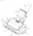
- FIG. 1 is a perspective views of the cleaning module 100 according to the embodiment of the present disclosure.
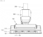
- FIG. 2 is a front view of the cleaning module 100 of FIG. 1 .
- FIG. 3 is a plan view of the cleaning module of FIG. 1 .
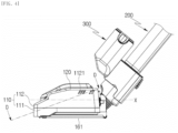
- FIG. 4 is a right side view of the cleaning module of FIG. 1 .
- FIG. 5 is a bottom view of the cleaning module of FIG. 1 .
- the cleaning module 100 is connected to the main body. Referring to FIG. 1 , the cleaning module 100 may be connected to the extension pipe 200 and may be indirectly connected to the main body through the extension pipe 200.
- a sub-battery 300 is installed in the extension pipe 200. Specifically, the sub-battery 300 may be disposed at the front end of the extension pipe 200.
- the sub-battery 300 is electrically connected to the cleaning module 100 and supplies electric power to each component disposed in the cleaning module 100.
- the sub-battery 300 may supply electric power to the heater 130 or may supply electric power to a mop motor 162.
- the sub-battery 300 may be electrically connected to the main battery. Accordingly, the sub-battery 300 may receive electric power from the main battery.
- the sub-battery 300 may be connected in series with the main battery. Accordingly, when the sub-battery 300 has insufficient stored electric energy, the sub-battery 300 and the main battery are connected in series to supply sufficient voltage power to the cleaning module 100.
- the sub-battery 300 may be connected in parallel with the main battery. Accordingly, a time for supplying electric power to the cleaning module 100 can be improved.
- the sub-battery 300 may be disposed at the front end of the extension pipe 200. Alternatively, the sub-battery 300 may be disposed on the lower portion of the extension pipe 200. By having such an arrangement, a center of gravity of a cleaner assembly in which the cleaning module 100 and the sub-battery 300 are coupled is disposed in the lower portion thereof, so that the cleaner can be easily steered.
- the sub-battery 300 may be disposed on the upper portion of the extension pipe 200. Specifically, the sub-battery 300 may be disposed above an imaginary line extending in the longitudinal direction of the extension pipe 200 from the center of the extension pipe 200.
- the cleaning module housing 110 forms an appearance of the cleaning module 100 and forms a space for receiving other components therein.
- the cleaning module housing 110 is connected to the main body. Referring to FIG. 1 , the cleaning module housing 110 is connected to the front end of the extension pipe 200, and the rear end of the extension pipe 200 is connected to the main body, and thus, the cleaning module housing 110 is indirectly connected to the main body through the extension pipe 200. Unlike this, although not shown, the cleaning module housing 110 may be directly connected to the main body.
- connection may be construed in various ways.
- air flow paths are connected to the main body, so that air including dust can flow to the main body through the cleaning module housing 110.
- the cleaning module housing 110 may be electrically connected to the main body, and current may flow from the main battery disposed in the main body to the cleaning module housing 110.
- a bucket 120 is mounted on the top surface of the cleaning module housing 110.
- An air inlet 1111 is formed on the front surface of the cleaning module housing 110, so that external air can be introduced into the cleaning module housing 110.
- a light emitting module 150 may be disposed under the front surface of the cleaning module housing 110 and may irradiate light to the floor in front of the cleaning module 100.
- An air outlet 1121 is formed on the side of the cleaning module housing 110, so that the air within the cleaning module housing 110 can be discharged to the outside.
- the mop 161 is disposed on the bottom surface of the cleaning module housing 110.
- the mop 161 may perform wet-cleaning by rubbing the cleaning area.
- the suction port 181 is disposed on the bottom surface of the cleaning module housing 110.
- the suction port 181 may perform dry-cleaning by sucking dust present on the floor.
- the shielding member 170 is disposed on the bottom surface of the cleaning module housing 110.
- the shielding member 170 shields the front space where the suction port 181 is disposed from the rear space where the mop 161 is disposed, and blocks the steam discharged from the mop 161 from diffusing into the suction port 181.
- the cleaning module housing 110 may be divided into a lower housing 111 and an upper housing 112.
- the lower housing 111 forms a portion of a side surface and a portion a lower surface of the cleaning module 100.
- the heater 130 is installed on the top surface of the lower housing 111.
- the air inlet 1111 is formed on the front surface of the lower housing 111.
- the light emitting module 150 is installed in the lower housing 111, and a hole through which light passes is formed in the front surface. The hole through which light passes is formed under the air inlet 1111.
- the mop is disposed on the bottom surface of the lower housing 111.
- One side of the bottom surface of the lower housing 111 is formed to have a groove recessed upward such that the mop is disposed.
- the suction port 181 is disposed on the bottom surface of the lower housing 111.
- the suction port 181 is disposed in front of the mop 161.
- a plurality of components for driving the cleaning module 100 are installed on the top surface of the lower housing 111.
- a lower partition wall 1112 is formed on the top surface of the lower housing 111.
- the lower partition wall 1112 is disposed around the heater 130 and blocks the heat emitted from the heater 130 from radiating to the outside.
- the lower partition wall 1112 is formed to protrude upward from the top surface of the lower housing 111.
- the lower partition wall 1112 is disposed outside the heater 130.
- the lower partition wall 1112 is disposed outside the heater 130, in such a way as to be spaced apart from the heater 130.
- the lower partition wall 1112 is disposed between the heater 130 and the mop motor 162. Specifically, when viewed from the top, the lower partition wall 1112 is disposed outside the heater 130 and disposed inside the mop motor 162. By having such an arrangement, the lower partition wall 1112 blocks the heat radiated from the heater 130 from reaching the mop motor 162, thereby preventing damage to the mop motor 162.
- the upper portion of the lower partition wall 1112 faces the lower portion of an upper partition wall 1122 and isolates the internal space in which the heater 130 is disposed from the external space in which other parts are disposed.
- An air flow path is formed outside the lower partition wall 1112. Specifically, the air introduced into the cleaning module housing 110 through the air inlet 1111 flows outside the lower partition wall 1112 and then flows toward the air outlet 1121.
- a shielding member insertion groove 1113 is formed in the bottom surface of the lower housing 111.
- the shielding member 170 is inserted into the shielding member insertion groove 1113 and installed.
- the upper housing 112 forms a portion of a side surface and a portion a top surface of the cleaning module 100.
- the upper housing 112 is coupled to the lower housing 111 and is disposed on the heater 130, in such a way as to be spaced apart from the heater 130.
- the bucket 120 is installed on the top surface.
- the air outlet 1121 is formed on the side of the upper housing 112.
- the upper housing 112 is disposed to be spaced apart from the heater 130.
- the heat radiated from the heater 130 is convected and reaches the upper housing 112.
- the heat is transferred by heat conduction in the upper housing 112, but the heat is transferred between the heater 130 and the upper housing 112 by thermal convection. Accordingly, the heat transfer type is switched, and thus, the heat transfer efficiency is reduced.
- the upper partition wall 1122 is formed in the upper housing 112.
- the upper partition wall 1122 is disposed on the bottom surface of the upper housing 112 and extends downward toward the heater 130.
- the upper partition wall 1122 surrounds at least a portion of the side surface of the heater 130, so that the heat radiated from the heater 130 is prevented from being convected to the side.
- the upper partition wall 1122 is disposed outside the heater 130.
- the upper partition wall 1122 is disposed outside the heater 130, in such a way as to be spaced apart from the heater 130.
- the upper partition wall 1122 is disposed between the heater 130 and the mop motor 162. Specifically, when viewed from the top, the upper partition wall 1122 is disposed outside the heater 130 and disposed inside the mop motor 162. By having such an arrangement, the upper partition wall 1122 blocks the heat radiated from the heater 130 from reaching the mop motor 162, thereby preventing damage to the mop motor 162.
- the lower portion of the upper partition wall 1122 faces the upper portion of the lower partition wall 1112 and isolates the internal space in which the heater 130 is disposed from the external space in which other parts are disposed.
- an air flow path is formed outside the upper partition wall 1122. Specifically, the air introduced into the cleaning module housing 110 through the air inlet 1111 flows outside the upper partition wall 1122 and then flows toward the air outlet 1121.
- a release button 1123 is disposed on the upper housing 112.
- the release button 1123 fixes the bucket 120 by being caught on a coupling hook 125 formed in the bucket 120.
- the release button 1123 operates, the release button 1123 is pressed down, the catch of the coupling hook 125 is released, and the bucket 120 is attachably detached.
- the release button 1123 may be disposed on the extension pipe placement portion 127 of the bucket 120.
- the upper housing 112 has a heat insulation coating surface 1124 formed on the inner surface thereof facing the heater 130.
- the heat insulation coating surface 1124 blocks the heat radiated from the heater 130 from being transferred to the upper housing 112.
- the heat insulation coating surface 1124 is disposed in a region partitioned by the upper partition wall 1122 among the inner surfaces of the upper housing 112. Accordingly, the heat insulation coating surface 1124 blocks the heat radiated upward from the heater 130 from being transmitted to the upper housing 112.
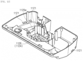
- the upper housing 112 includes a bucket seating part 1125.
- the bucket seating part 1125 is a groove recessed downward from the top surface of the upper housing 112.
- the bucket 120 is seated on the bucket seating part 1125 and is installed on the upper housing 112.
- the bucket seating part 1125 may be divided into storage part insertion grooves 1125a to 1125c, an air channel insertion part 1125d, and a guide protrusion 1125e.
- a storage part 123 of the bucket 120 is inserted and seated in the storage part insertion grooves 1125a to 1125c.
- the storage part insertion grooves 1125a to 1125c may be formed in a U-shape with an open rear.
- the front storage part insertion groove 1125a is formed at the front end of the bucket seating part 1125 and extends to the left and right.
- a front storage part 123a is inserted and seated in the front storage part insertion groove 1125a.
- the left storage part insertion groove 1125b extends rearward from the left end of the front storage part insertion groove 1125a. A left storage part 123b is inserted and seated in the left storage part insertion groove 1125b.
- the right storage part insertion groove 1125c extends rearward from the right end of the front storage part insertion groove 1125a.
- a right storage part 123c is inserted and seated in the right storage part insertion groove 1125c.
- a through hole is formed in a position where the connection portion overlaps vertically a drain port 122 of the bucket 120.
- An air channel 128 formed in the bucket 120 is inserted into the air channel insertion groove 1125d.
- the air channel insertion groove 1125d is disposed to overlap vertically the air channel 128.
- the air channel insertion groove 1125d extends to the left storage part insertion groove 1125b and the right storage part insertion groove 1125c.
- the guide protrusion 1125e is a component for guiding the bucket 120 to a correct position when the bucket 120 is inserted into the bucket seating part 1125.
- the bucket 120 is formed with a groove for inserting the guide projection (1125e) into a position corresponding to the guide protrusion 1125e.
- the guide protrusion 1125e is formed at the rear end of the right storage part insertion groove 1125c.
- the guide protrusion 1125e may be formed at the rear end of the left storage part insertion groove 1125b.
- the guide protrusion 1125e is alternatively formed in any one of the right storage part insertion groove 1125c and the left storage part insertion groove 1125b. This intends to obtain a certain amount or more of a storage capacity of the storage part 123.
- a heater placement portion 1126 is disposed in the upper housing 112.
- the heater placement portion 1126 is a component that forms a space into which at least a portion of the heater 130 is inserted.
- the heater placement portion 1126 is a surface disposed to vertically overlap the heater 130 among the bottom surfaces of the upper housing 112.
- the heater placement portion 1126 is formed by recessing upward the bottom surface of the upper housing 112. At least a portion of the heater 130 is inserted into the recessed groove of the heater placement portion 1126, the height of the cleaning module 100 can be reduced.
- the heater placement portion 1126 may be formed to have a shape similar to a quadrangle. Specifically, the heater placement portion 1126 may be formed in a quadrangular shape of which each corner is formed as a curved surface without being bent.
- an area projected from the heater placement portion 1126 to the ground is larger than an area projected from the heater 130 to the ground.
- the heater placement portion 1126 of the upper housing 112 is formed to correspond to a heater placement portion 126 of the bucket 120. That is, a first inclined surface 1126a of the heater placement portion 1126 of the upper housing 112 corresponds to a first inclined surface 126a of the heater placement portion 126 of the bucket 120, and a second inclined surface 1126b of the heater placement portion 1126 of the upper housing 112 corresponds to the second inclined surface 126b of the heater placement portion 126 of the bucket 120.
- a third inclined surface 1126c of the heater placement portion 1126 of the upper housing 112 corresponds to a third inclined surface 126c of the heater placement portion 126 of the bucket 120. Accordingly, the water droplets formed on the heater placement portion 1126 of the upper housing 112 do not fall on the heater 130, but flow down along the first to third inclined surfaces 1126a to 1126c.
- the heater 130 is disposed to be inclined from the ground, and the cleaning module housing 110 includes an inclined surface disposed parallel to the top surface of the heater 130.
- the second inclined surface 1126b of the cleaning module housing 110 may be disposed parallel to the heater 130.
- the air inlet 1111 is formed on one side of the cleaning module housing 110.
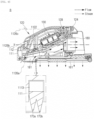
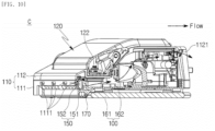
- the air outlet 1121 is formed on the cleaning module housing 110 and is disposed above the air inlet 1111. Air is introduced into the cleaning module 100 through the air inlet 1111 and is heated by absorbing the heat remaining in the internal space of the cleaning module 100. The heated air expands and rises. Therefore, the heated air is located in the upper part of the internal space of the cleaning module 100, and since the air outlet 1121 is disposed above the air inlet 1111, the air can be easily discharged to the outside of the cleaning module 100 through the air outlet 1121.
- the air inlet 1111 is disposed below the heater 130 and the air outlet 1121 is disposed above the heater 130. Accordingly, the air introduced into the internal space of the cleaning module 100 through the air inlet 1111 goes via the outside of the heater 130 and is discharged to the outside of the cleaning module 100 through the air outlet 1121. Accordingly, the introduced air passes through the outside of the heater 130, absorbs residual heat that may exist in the upper partition wall 1122 or the lower partition wall 1112, and thus, can be discharged to the outside of the cleaning module 100.
- the air outlet 1121 is disposed in an opposite direction to the air inlet 1111 about the rolling axis (x).
- the air inlet 1111 is disposed below the rolling axis (x), and the air outlet 1121 is disposed above the rolling axis (x).
- the rolling axis (x) is disposed horizontally to the ground and along the travel direction.
- the air inlet 1111 is disposed below the rolling axis (x) and the air outlet 1121 is disposed above the rolling axis (x), so that the air within the cleaning module 100 may always have an upward flow.
- the air outlet 1121 is disposed more outside than the air inlet 1111. Specifically, referring to FIG. 1 , the right air outlet 1121 is disposed on the right side of the air inlet 1111, and the left air outlet 1121 is disposed on the left side of the air inlet 1111.
- the air flows backward from the air inlet 1111, and the introduced air collides with the upper partition wall 1122 or the lower partition wall 1112, so that the direction of the air is changed into an outside direction and the air flows along the partition walls 1112 and 1122. Accordingly, the air flows along the partition walls 1112 and 1122 and absorbs the heat radiated from the outer surfaces of the partition walls 1112 and 1122, preventing the heat from being transferred to other components.
- the air outlet 1121 is disposed on the side surface of the cleaning module housing 110. Specifically, the air outlet 1121 is formed on the side surface of the upper housing 112. Referring to FIG. 1 , the left air outlet 1121 is formed on the left side of the upper housing 112, and the right air outlet 1121 is formed on the right side of the upper housing 112.
- the air flows from the front to the rear at the air inlet 1111, and the flow direction of the air at the air outlet 1121 is changed and the air flow from the inside to the outside. Therefore, as a vortex is created in the air flow in the internal space of the cleaning module 100, there is an effect that the heat remaining in the parts disposed in the corner can also be absorbed.
- the air outlet 1121 is disposed behind the air inlet 1111.
- the cleaning module 100 moves forward and cleans the cleaning area.
- the air in front of the cleaning module 100 can be easily introduced into the internal space of the cleaning module 100 through the air inlet 1111 as the cleaning module 100 moves forward. A sufficient flow of air may be supplied to the inside of the cleaning module 100.
- the air inlet 1111 is disposed on the front surface of the cleaning module housing 110. Specifically, the air inlet 1111 is formed on the front surface of the lower housing 111.
- the heater 130 is a component which generates steam from water.
- the heater 130 is disposed within the cleaning module housing 110. Specifically, the heater 130 is installed on the top surface of the lower housing 111.
- a water inlet 131 is a hole formed at the inlet of the heater 130. Through the water inlet 131, water is introduced into the heater 130. The water inlet 131 is connected to a heater hose 143.
- the steam outlet 132 is a hole formed at the outlet end of the heater 130. Through the steam outlet 132, steam is discharged from the heater 130. The steam outlet 132 is connected to the mop.
- the water inlet 131 is disposed above the steam outlet 132. Accordingly, the water is heated as it flows from the top to the bottom by gravity, and is phase-changed to steam.
- the heater 130 is disposed to be inclined. Specifically, the heater 130 is disposed to be inclined at a certain angle with respect to the ground.
- the rear of the heater 130 is disposed above the front of the heater 130. That is, the heater 130 has a backward-upward inclination. Accordingly, the water is heated as it flows from the rear upper portion to the front lower portion of the heater 130, and is phase-changed to steam.
- the bucket 120 supplies water to the heater 130.
- the bucket 120 stores water, and the stored water flows into the heater 130 and is phase-changed to steam.
- the bucket 120 is disposed in the housing. Specifically, the bucket 120 is mounted on the bucket seating part 1125 formed in the upper housing 112.
- the bucket 120 is disposed on the heater 130. Specifically, the bucket 120 is disposed on the heater 130, in such a way as to be spaced apart from the heater 130.
- the bucket 120 may be disposed on the heater 130 with the upper housing 112 placed therebetween.
- the bucket 120 includes a water supply port 121.
- the water supply port 121 is a hole through which water flows into the bucket 120.
- the water supply port 121 is formed in the side surface of the bucket 120.
- the water supply port 121 may be formed in both side surfaces of the bucket 120.
- the bucket 120 includes a drain port 122.
- the drain port 122 is a hole through which the water stored in the bucket 120 is discharged. The water discharged from the drain port 122 flows to the heater 130.
- the drain port 122 is formed in the bottom surface of the bucket 120.
- the drain port 122 may be disposed at a connection portion between the front storage part 123a and the right storage part 123c.
- the bucket 120 includes the storage part 123.
- the storage part 123 is an internal space of the bucket 120 and can store water. When the bucket 120 is viewed from the top, the storage part 123 may be formed in a U-shape with an open rear. The storage part 123 may be divided into the front storage part 123a, the left storage part 123b, and the right storage part 123c.
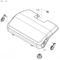
- the bucket 120 includes an air hole 124. Air can be introduced into the bucket 120 through the air hole 124. When the water stored within the bucket 120 is discharged to the outside, the pressure within the bucket 120 is lowered and air is introduced into the bucket 120 through the air hole 124 in order to compensate for the lowered pressure.
- the air hole 124 is formed in the upper portion of the bucket 120. Specifically, the air hole 124 is formed in the rear end of the left storage part 123b. Alternatively, the air hole 124 may be formed in the rear end of the right storage part 123c.
- a coupling hook 125 is a component for fixing the bucket 120 to the upper housing 112.
- the coupling hook 125 is caught and fixed to the release button 1123.
- the coupling hook 125 is formed at the rear end of the bucket 120. Specifically, the coupling hook 125 is formed in the extension pipe placement portion 127.
- the feed water pump 141 is a component which causes the water within the cleaning module 100 to flow.
- the feed water pump 141 pressurizes the water within the bucket 120 and sends it to the heater 130.
- the inlet of the feed water pump 141 is connected to the outlet of a tank hose 142, and the outlet of the feed water pump 141 is connected to the heater hose 143.
- the tank hose 142 connects the bucket 120 and the feed water pump 141.
- the tank hose 142 guides the water stored in the bucket 120 to the feed water pump 141.
- the heater hose 143 connects the feed water pump 141 and the heater 130.
- the heater hose 143 guides the water pressurized by the feed water pump 141 to the heater 130.
- the light emitting module 150 illuminates the front of the cleaning module 100 and confirms foreign substances existing in front of the cleaning module 100.
- the light emitting module 150 irradiates light to the floor in front of the cleaning module 100.
- the light emitting module 150 may be disposed behind the air inlet 1111. By having such an arrangement, the light emitting module 150 can be cooled by the air introduced from the air inlet 1111.
- a plurality of the light emitting modules 150 may be disposed to the left or right along the front surface.
- the light emitting module 150 may include a light emitting member 151 and a diffusion plate 152.
- the light emitting member 151 may be composed of a plurality of LEDs.
- the light emitting member 151 emits light forward or downward.
- the diffusion plate 152 is disposed in front of the light emitting member 151 and diffuses the light emitted from the light emitting member 151.
- the diffusion plate 152 may have a forwardly convex curved surface. By having such an arrangement, the air introduced from the air inlet 1111 moves along the diffusion plate 152 and air resistance can be minimized.
- a mop assembly 160 is a component for cleaning the floor surface with water or steam.
- the mop assembly 160 receives steam from the heater 130 and performs wet-cleaning on the floor surface by friction and steam.
- the mop assembly 160 may include the mop 161 and the mop motor 162.
- the mop 161 is disposed on the bottom surface of the lower housing 111.
- the lower housing 111 is formed with a groove recessed upward such that the mop 161 can be disposed, and at least a portion of the mop 161 is inserted into the groove, so that the mop 161 is installed on the lower housing 111.
- the mop 161 may be formed in a circular shape when viewed from the top. In the center of the mop 161, a rotation axis extending up and down is formed. The mop 161 may clean the floor surface by friction while rotating about the rotation axis.
- a pair of right and left mops 161 may be arranged about the rolling axis (x).
- the mop motor 162 is a component that rotates the mop 161.
- the mop motor 162 is disposed on the mop 161 and is disposed on the rotation axis of the mop 161.
- the mop motor 162 is installed on the top surface of the lower housing 111.
- the mop motor 162 is disposed to correspond to the number of mops 161.
- a pair of right and left mop motors 162 may be arranged about the rolling axis (x).
- the mop motor 162 is disposed on the side of the heater 130.
- the upper partition wall 1122 or the lower partition wall 1112 is disposed between the mop motor 162 and the heater 130 and blocks the heat of the heater 130 from being transferred to the mop motor 162.
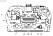
- the mop motor 162 is disposed on the flow path of the air introduced into the air inlet 1111. Specifically, referring to FIG. 10 , when viewed from the side, the mop motor 162 is disposed above the air inlet 1111 and disposed below the air outlet 1121. In addition, referring to FIG. 11 , the mop motor 162 is disposed outside the air inlet 1111 and disposed inside the air outlet 1121. By having such an arrangement, the mop motor 162 is sufficiently cooled by the introduced air, and thus, is not damaged by the heat of the heater.
- the shielding member 170 shields the front space where the suction port 181 is disposed and the rear space where the mop 161 is disposed, thereby blocking the steam emitted from the mop 161 from diffusing into the suction port 181.
- the shielding member 170 is disposed on the cleaning module housing 110 and is disposed between the suction port 181 and the mop 161.
- the heat or steam emitted from the mop 161 may diffuse forward and be introduced into the suction port 181.
- the steam introduced through the suction port 181 reaches the main body of the cleaner through the dust passage 180 and the extension pipe 200.
- the dust passage 180, the extension pipe 200, and the main body of the cleaner are overheated. Therefore, if the user touches the components, the user may get burned and other electronic equipment located near the components may be damaged.
- the cleaner according to the present disclosure includes the shielding member 170, thereby blocking the heat or steam emitted from the mop 161 from flowing into the suction port 181.
- the shielding member 170 may be divided into a central portion 171, a first extension portion 172, and a second extension portion 173.
- the central portion 171 is disposed behind the suction port 181 and extends straight outward.
- the first extension portion 172 extends outward from the end of the central portion 171 and extends in a curved line.
- the second extension portion 173 extends outward from the rotation axis of the mop 161 and extends in a straight line.
- the first extension portion 172 has a forwardly or inwardly convex curved surface. By having such an arrangement, the inner end of the first extension portion 172 is disposed behind the outer end. Accordingly, when the cleaning module 1000 moves forward, the dust remaining in the cleaning area may be collected in the central portion along the first extension portion 172 and may be sucked into the suction port 181, so that the cleaning performance can be improved.
- the second extension portion 173 is disposed in front of an auxiliary wheel.
- the shielding member 170 may include a plurality of protrusions 170a and 170b.
- the first protrusion 170a protrudes toward the cleaning area.
- the second protrusion 170b is disposed to be spaced apart from the first protrusion 170a behind the first protrusion 170a, and protrudes toward the cleaning area.
- the shielding member 170 may have a W-shape in cross-section when viewed from the side.
- the second protrusion 170b further protrudes downward than the first protrusion 170a.
- the first protrusion 170a is disposed in front of the second protrusion 170b and sweeps larger dust away.
- the second protrusion 170b is disposed behind the first protrusion 170a and sweeps away smaller dust thoroughly.
- the shielding member 170 according to the present disclosure is provided with the two-stage protrusions 170a and 170b, thereby sweeping away dust more effectively.
- air including dust flows through the dust passage 180.
- the inlet of the dust passage 180 is connected to the suction port 181, and the outlet of the dust passage 180 is connected to the extension pipe 200.
- the suction port 181 is a hole through which dust and air which exist in the cleaning area are introduced into the cleaning module 180.
- the suction port 181 is formed at the front portion of the bottom surface of the lower housing 111.
- the suction port 181 is disposed between the left mop 161 and the right mop 161.
- the dust passage 180 is disposed under the heater 130.
- the heat of the heater 130 may be slightly emitted downward.
- a PCB 190 is a board on which a controller (not shown) for controlling the cleaning module 100 is disposed, a current can flow, and communication lines can be disposed.
- the PCB 190 is electrically connected to the main body.
- the PCB 190 and parts installed on the PCB 190 have a characteristic that they are vulnerable to heat.
- the PCB 190 and parts may be cooled by the air which is introduced into the air inlet 1111 and discharged through the air outlet 1121.
- the PCB 190 is disposed on the flow path of the air introduced into the air inlet 1111. Referring to FIG. 7 , the PCB 190 may be disposed above the right mop motor 162. Accordingly, when viewed from the side, the PCB 190 is disposed above the air inlet 1111 and disposed below the air outlet 1121. Also, the PCB 190 is disposed outside the air inlet 1111 and disposed inside the air outlet 1121. By having such an arrangement, the PCB 190 is sufficiently cooled by the introduced air, so that the PCB is not damaged by the heat of the heater 130.
- the cleaning module housing 110 includes the air inlet 1111 through which air is introduced and the air outlet 1121 through which the air is discharged.
- the air outlet 1121 is disposed above the air inlet 1111.
- the air inlet 1111 may be disposed below the heater 130, and the air outlet 1121 may be disposed above the heater 130.
- the air flowing within the cleaning module 100 flows close to the heater 130, so that the air may deprive the heat from the heater 130 and release the heat to the outside of the cleaning module 100. Also, it is possible to prevent the electronic equipment from being damaged by the heat emitted from the heater 130.
- the air outlet 1121 may be disposed more outside than the air inlet 1111.
- the change of the flow direction of the air introduced to the rear from the air inlet 1111 is changed, and thus, the air is discharged laterally from the air outlet 1121. Accordingly, in the internal space of the cleaning module 110, a vortex is created in the air flow, so that there is an effect that heat remaining in the parts disposed in the corner can also be absorbed.
- the lower partition wall 1112 or the upper partition wall 1122 is disposed around the heater 130 and isolates the internal space in which the heater 130 is disposed from the external space in which other components are disposed. Accordingly, the heat emitted from the heater 130 is prevented from radiating to the outside. In addition, the heat emitted from the heater 130 is maintained around the heater 130, and the thermal efficiency of the heater 130 can be improved by the heat insulation effect.
- the mop motor 162 or the PCB 190 is disposed on the flow path of the air introduced into the air inlet. By having such an arrangement, the mop motor 162 or the PCB 190 can be sufficiently cooled, and thus, is not damaged by the heat emitted from the heater 130.
- the shielding member 170 is disposed on the cleaning module housing 110 and is disposed between the suction port 181 and the mop 161.
- the shielding member 170 blocks the heat or steam emitted from the mop 161 from flowing into the suction port 181, so that the steam flows through the extension pipe 200 through the dust passage 180, thereby preventing thermal damage to peripheral parts and the risk of burns to the user.
Landscapes
- Engineering & Computer Science (AREA)
- Mechanical Engineering (AREA)
- Electric Vacuum Cleaner (AREA)
- Cleaning By Liquid Or Steam (AREA)
Applications Claiming Priority (3)
| Application Number | Priority Date | Filing Date | Title |
|---|---|---|---|
| US202163203570P | 2021-07-27 | 2021-07-27 | |
| KR1020210172185A KR20230017094A (ko) | 2021-07-27 | 2021-12-03 | 청소기 |
| PCT/KR2022/011009 WO2023008896A1 (ko) | 2021-07-27 | 2022-07-27 | 청소기 |
Publications (2)
| Publication Number | Publication Date |
|---|---|
| EP4378367A1 true EP4378367A1 (de) | 2024-06-05 |
| EP4378367A4 EP4378367A4 (de) | 2025-07-30 |
Family
ID=85087056
Family Applications (1)
| Application Number | Title | Priority Date | Filing Date |
|---|---|---|---|
| EP22849872.1A Pending EP4378367A4 (de) | 2021-07-27 | 2022-07-27 | Reiniger |
Country Status (4)
| Country | Link |
|---|---|
| US (1) | US20240374104A1 (de) |
| EP (1) | EP4378367A4 (de) |
| TW (1) | TWI860534B (de) |
| WO (1) | WO2023008896A1 (de) |
Families Citing this family (1)
| Publication number | Priority date | Publication date | Assignee | Title |
|---|---|---|---|---|
| CN120292465A (zh) * | 2025-05-28 | 2025-07-11 | 苏州荣炫电器有限公司 | 一种灯具及其加工模具、地刷头和吸尘器 |
Family Cites Families (10)
| Publication number | Priority date | Publication date | Assignee | Title |
|---|---|---|---|---|
| US7134164B2 (en) * | 2002-01-25 | 2006-11-14 | Alton James R | Vacuum cleaner nozzle assembly having edge-cleaning ducts |
| JP3108311U (ja) * | 2004-10-20 | 2005-04-14 | 謀燦 蔡 | 蒸気式モップ |
| KR100862580B1 (ko) * | 2007-06-05 | 2008-10-09 | 주식회사 홈파워 | 스팀청소기 |
| KR101494380B1 (ko) * | 2013-04-19 | 2015-02-23 | 김병미 | 진공청소기 |
| CN105816121A (zh) * | 2016-06-03 | 2016-08-03 | 江苏纽唯盛机电有限公司 | 一种无线蒸汽拖把及其使用方法 |
| CN206183196U (zh) * | 2016-07-20 | 2017-05-24 | 佛山市顺德区盛熙电器制造有限公司 | 一种擦地装置 |
| US10602902B2 (en) * | 2017-02-22 | 2020-03-31 | Bissell Homecare, Inc. | Motorized floor mop |
| KR102128190B1 (ko) * | 2019-01-24 | 2020-07-09 | 임택순 | 스팀 물걸레 진공청소기 |
| KR102281840B1 (ko) * | 2019-09-03 | 2021-07-23 | 엘지전자 주식회사 | 이동로봇의 도킹장치 |
| AU2022224917A1 (en) * | 2021-02-26 | 2023-09-28 | Lg Electronics Inc. | Cleaner |
-
2022
- 2022-07-21 TW TW111127435A patent/TWI860534B/zh active
- 2022-07-27 WO PCT/KR2022/011009 patent/WO2023008896A1/ko not_active Ceased
- 2022-07-27 US US18/292,776 patent/US20240374104A1/en active Pending
- 2022-07-27 EP EP22849872.1A patent/EP4378367A4/de active Pending
Also Published As
| Publication number | Publication date |
|---|---|
| TW202304368A (zh) | 2023-02-01 |
| TWI860534B (zh) | 2024-11-01 |
| EP4378367A4 (de) | 2025-07-30 |
| US20240374104A1 (en) | 2024-11-14 |
| WO2023008896A1 (ko) | 2023-02-02 |
Similar Documents
| Publication | Publication Date | Title |
|---|---|---|
| EP4162855A1 (de) | Oberflächenreinigungsvorrichtung | |
| CN116981386A (zh) | 清洁器 | |
| US20240130591A1 (en) | Cleaner | |
| US20240138644A1 (en) | Cleaner | |
| CN113317725A (zh) | 基站设备及清洁系统 | |
| US20240374104A1 (en) | Cleaner | |
| KR20230017094A (ko) | 청소기 | |
| TWI842021B (zh) | 清掃機 | |
| TWI852559B (zh) | 吸塵器 | |
| KR20220057138A (ko) | 청소기 | |
| KR20230017095A (ko) | 청소기 | |
| KR20230087858A (ko) | 청소기 | |
| CN111956123A (zh) | 蒸汽吸尘器 | |
| CN222604480U (zh) | 一种可躺平清洁的表面清洁装置 | |
| CN118900657A (zh) | 吸尘器的湿抹布模块 | |
| TW202600057A (zh) | 清掃機器人站 | |
| KR20240172025A (ko) | 청소기용 배터리 및 청소기 | |
| KR20250155643A (ko) | 로봇 청소기 스테이션 | |
| TW202510795A (zh) | 清掃機器人站 |
Legal Events
| Date | Code | Title | Description |
|---|---|---|---|
| STAA | Information on the status of an ep patent application or granted ep patent |
Free format text: STATUS: THE INTERNATIONAL PUBLICATION HAS BEEN MADE |
|
| PUAI | Public reference made under article 153(3) epc to a published international application that has entered the european phase |
Free format text: ORIGINAL CODE: 0009012 |
|
| STAA | Information on the status of an ep patent application or granted ep patent |
Free format text: STATUS: REQUEST FOR EXAMINATION WAS MADE |
|
| 17P | Request for examination filed |
Effective date: 20240226 |
|
| AK | Designated contracting states |
Kind code of ref document: A1 Designated state(s): AL AT BE BG CH CY CZ DE DK EE ES FI FR GB GR HR HU IE IS IT LI LT LU LV MC MK MT NL NO PL PT RO RS SE SI SK SM TR |
|
| DAV | Request for validation of the european patent (deleted) | ||
| DAX | Request for extension of the european patent (deleted) | ||
| A4 | Supplementary search report drawn up and despatched |
Effective date: 20250630 |
|
| RIC1 | Information provided on ipc code assigned before grant |
Ipc: A47L 11/40 20060101AFI20250624BHEP Ipc: A47L 13/22 20060101ALI20250624BHEP Ipc: A47L 9/30 20060101ALI20250624BHEP Ipc: A47L 11/30 20060101ALI20250624BHEP Ipc: A47L 11/34 20060101ALI20250624BHEP |