EP4378427A1 - Implant médicale de collecte des débris d'abrasion d'articulation , composant d'endoprothèse d'articulation et endoprothèse d'articulation - Google Patents
Implant médicale de collecte des débris d'abrasion d'articulation , composant d'endoprothèse d'articulation et endoprothèse d'articulation Download PDFInfo
- Publication number
- EP4378427A1 EP4378427A1 EP23213627.5A EP23213627A EP4378427A1 EP 4378427 A1 EP4378427 A1 EP 4378427A1 EP 23213627 A EP23213627 A EP 23213627A EP 4378427 A1 EP4378427 A1 EP 4378427A1
- Authority
- EP
- European Patent Office
- Prior art keywords
- joint
- wear
- collection device
- collection
- device implant
- Prior art date
- Legal status (The legal status is an assumption and is not a legal conclusion. Google has not performed a legal analysis and makes no representation as to the accuracy of the status listed.)
- Pending
Links
Images


Classifications
-
- A—HUMAN NECESSITIES
- A61—MEDICAL OR VETERINARY SCIENCE; HYGIENE
- A61F—FILTERS IMPLANTABLE INTO BLOOD VESSELS; PROSTHESES; DEVICES PROVIDING PATENCY TO, OR PREVENTING COLLAPSING OF, TUBULAR STRUCTURES OF THE BODY, e.g. STENTS; ORTHOPAEDIC, NURSING OR CONTRACEPTIVE DEVICES; FOMENTATION; TREATMENT OR PROTECTION OF EYES OR EARS; BANDAGES, DRESSINGS OR ABSORBENT PADS; FIRST-AID KITS
- A61F2/00—Filters implantable into blood vessels; Prostheses, i.e. artificial substitutes or replacements for parts of the body; Appliances for connecting them with the body; Devices providing patency to, or preventing collapsing of, tubular structures of the body, e.g. stents
- A61F2/02—Prostheses implantable into the body
- A61F2/30—Joints
- A61F2/38—Joints for elbows or knees
-
- A—HUMAN NECESSITIES
- A61—MEDICAL OR VETERINARY SCIENCE; HYGIENE
- A61F—FILTERS IMPLANTABLE INTO BLOOD VESSELS; PROSTHESES; DEVICES PROVIDING PATENCY TO, OR PREVENTING COLLAPSING OF, TUBULAR STRUCTURES OF THE BODY, e.g. STENTS; ORTHOPAEDIC, NURSING OR CONTRACEPTIVE DEVICES; FOMENTATION; TREATMENT OR PROTECTION OF EYES OR EARS; BANDAGES, DRESSINGS OR ABSORBENT PADS; FIRST-AID KITS
- A61F2/00—Filters implantable into blood vessels; Prostheses, i.e. artificial substitutes or replacements for parts of the body; Appliances for connecting them with the body; Devices providing patency to, or preventing collapsing of, tubular structures of the body, e.g. stents
- A61F2/02—Prostheses implantable into the body
- A61F2/30—Joints
- A61F2/32—Joints for the hip
-
- A—HUMAN NECESSITIES
- A61—MEDICAL OR VETERINARY SCIENCE; HYGIENE
- A61F—FILTERS IMPLANTABLE INTO BLOOD VESSELS; PROSTHESES; DEVICES PROVIDING PATENCY TO, OR PREVENTING COLLAPSING OF, TUBULAR STRUCTURES OF THE BODY, e.g. STENTS; ORTHOPAEDIC, NURSING OR CONTRACEPTIVE DEVICES; FOMENTATION; TREATMENT OR PROTECTION OF EYES OR EARS; BANDAGES, DRESSINGS OR ABSORBENT PADS; FIRST-AID KITS
- A61F2/00—Filters implantable into blood vessels; Prostheses, i.e. artificial substitutes or replacements for parts of the body; Appliances for connecting them with the body; Devices providing patency to, or preventing collapsing of, tubular structures of the body, e.g. stents
- A61F2/02—Prostheses implantable into the body
- A61F2/30—Joints
- A61F2/38—Joints for elbows or knees
- A61F2/3804—Joints for elbows or knees for elbows
-
- A—HUMAN NECESSITIES
- A61—MEDICAL OR VETERINARY SCIENCE; HYGIENE
- A61F—FILTERS IMPLANTABLE INTO BLOOD VESSELS; PROSTHESES; DEVICES PROVIDING PATENCY TO, OR PREVENTING COLLAPSING OF, TUBULAR STRUCTURES OF THE BODY, e.g. STENTS; ORTHOPAEDIC, NURSING OR CONTRACEPTIVE DEVICES; FOMENTATION; TREATMENT OR PROTECTION OF EYES OR EARS; BANDAGES, DRESSINGS OR ABSORBENT PADS; FIRST-AID KITS
- A61F2/00—Filters implantable into blood vessels; Prostheses, i.e. artificial substitutes or replacements for parts of the body; Appliances for connecting them with the body; Devices providing patency to, or preventing collapsing of, tubular structures of the body, e.g. stents
- A61F2/02—Prostheses implantable into the body
- A61F2/30—Joints
- A61F2/40—Joints for shoulders
-
- A—HUMAN NECESSITIES
- A61—MEDICAL OR VETERINARY SCIENCE; HYGIENE
- A61F—FILTERS IMPLANTABLE INTO BLOOD VESSELS; PROSTHESES; DEVICES PROVIDING PATENCY TO, OR PREVENTING COLLAPSING OF, TUBULAR STRUCTURES OF THE BODY, e.g. STENTS; ORTHOPAEDIC, NURSING OR CONTRACEPTIVE DEVICES; FOMENTATION; TREATMENT OR PROTECTION OF EYES OR EARS; BANDAGES, DRESSINGS OR ABSORBENT PADS; FIRST-AID KITS
- A61F2/00—Filters implantable into blood vessels; Prostheses, i.e. artificial substitutes or replacements for parts of the body; Appliances for connecting them with the body; Devices providing patency to, or preventing collapsing of, tubular structures of the body, e.g. stents
- A61F2/02—Prostheses implantable into the body
- A61F2/30—Joints
- A61F2/42—Joints for wrists or ankles; for hands, e.g. fingers; for feet, e.g. toes
-
- A—HUMAN NECESSITIES
- A61—MEDICAL OR VETERINARY SCIENCE; HYGIENE
- A61F—FILTERS IMPLANTABLE INTO BLOOD VESSELS; PROSTHESES; DEVICES PROVIDING PATENCY TO, OR PREVENTING COLLAPSING OF, TUBULAR STRUCTURES OF THE BODY, e.g. STENTS; ORTHOPAEDIC, NURSING OR CONTRACEPTIVE DEVICES; FOMENTATION; TREATMENT OR PROTECTION OF EYES OR EARS; BANDAGES, DRESSINGS OR ABSORBENT PADS; FIRST-AID KITS
- A61F2/00—Filters implantable into blood vessels; Prostheses, i.e. artificial substitutes or replacements for parts of the body; Appliances for connecting them with the body; Devices providing patency to, or preventing collapsing of, tubular structures of the body, e.g. stents
- A61F2/02—Prostheses implantable into the body
- A61F2/30—Joints
- A61F2/44—Joints for the spine, e.g. vertebrae, spinal discs
- A61F2/442—Intervertebral or spinal discs, e.g. resilient
- A61F2/4425—Intervertebral or spinal discs, e.g. resilient made of articulated components
-
- A—HUMAN NECESSITIES
- A61—MEDICAL OR VETERINARY SCIENCE; HYGIENE
- A61F—FILTERS IMPLANTABLE INTO BLOOD VESSELS; PROSTHESES; DEVICES PROVIDING PATENCY TO, OR PREVENTING COLLAPSING OF, TUBULAR STRUCTURES OF THE BODY, e.g. STENTS; ORTHOPAEDIC, NURSING OR CONTRACEPTIVE DEVICES; FOMENTATION; TREATMENT OR PROTECTION OF EYES OR EARS; BANDAGES, DRESSINGS OR ABSORBENT PADS; FIRST-AID KITS
- A61F2/00—Filters implantable into blood vessels; Prostheses, i.e. artificial substitutes or replacements for parts of the body; Appliances for connecting them with the body; Devices providing patency to, or preventing collapsing of, tubular structures of the body, e.g. stents
- A61F2/02—Prostheses implantable into the body
- A61F2/30—Joints
- A61F2/32—Joints for the hip
- A61F2/36—Femoral heads ; Femoral endoprostheses
- A61F2/3662—Femoral shafts
-
- A—HUMAN NECESSITIES
- A61—MEDICAL OR VETERINARY SCIENCE; HYGIENE
- A61F—FILTERS IMPLANTABLE INTO BLOOD VESSELS; PROSTHESES; DEVICES PROVIDING PATENCY TO, OR PREVENTING COLLAPSING OF, TUBULAR STRUCTURES OF THE BODY, e.g. STENTS; ORTHOPAEDIC, NURSING OR CONTRACEPTIVE DEVICES; FOMENTATION; TREATMENT OR PROTECTION OF EYES OR EARS; BANDAGES, DRESSINGS OR ABSORBENT PADS; FIRST-AID KITS
- A61F2/00—Filters implantable into blood vessels; Prostheses, i.e. artificial substitutes or replacements for parts of the body; Appliances for connecting them with the body; Devices providing patency to, or preventing collapsing of, tubular structures of the body, e.g. stents
- A61F2/02—Prostheses implantable into the body
- A61F2/30—Joints
- A61F2/38—Joints for elbows or knees
- A61F2/3859—Femoral components
-
- A—HUMAN NECESSITIES
- A61—MEDICAL OR VETERINARY SCIENCE; HYGIENE
- A61F—FILTERS IMPLANTABLE INTO BLOOD VESSELS; PROSTHESES; DEVICES PROVIDING PATENCY TO, OR PREVENTING COLLAPSING OF, TUBULAR STRUCTURES OF THE BODY, e.g. STENTS; ORTHOPAEDIC, NURSING OR CONTRACEPTIVE DEVICES; FOMENTATION; TREATMENT OR PROTECTION OF EYES OR EARS; BANDAGES, DRESSINGS OR ABSORBENT PADS; FIRST-AID KITS
- A61F2/00—Filters implantable into blood vessels; Prostheses, i.e. artificial substitutes or replacements for parts of the body; Appliances for connecting them with the body; Devices providing patency to, or preventing collapsing of, tubular structures of the body, e.g. stents
- A61F2/02—Prostheses implantable into the body
- A61F2/30—Joints
- A61F2/38—Joints for elbows or knees
- A61F2/3886—Joints for elbows or knees for stabilising knees against anterior or lateral dislocations
-
- A—HUMAN NECESSITIES
- A61—MEDICAL OR VETERINARY SCIENCE; HYGIENE
- A61F—FILTERS IMPLANTABLE INTO BLOOD VESSELS; PROSTHESES; DEVICES PROVIDING PATENCY TO, OR PREVENTING COLLAPSING OF, TUBULAR STRUCTURES OF THE BODY, e.g. STENTS; ORTHOPAEDIC, NURSING OR CONTRACEPTIVE DEVICES; FOMENTATION; TREATMENT OR PROTECTION OF EYES OR EARS; BANDAGES, DRESSINGS OR ABSORBENT PADS; FIRST-AID KITS
- A61F2/00—Filters implantable into blood vessels; Prostheses, i.e. artificial substitutes or replacements for parts of the body; Appliances for connecting them with the body; Devices providing patency to, or preventing collapsing of, tubular structures of the body, e.g. stents
- A61F2/02—Prostheses implantable into the body
- A61F2/30—Joints
- A61F2/38—Joints for elbows or knees
- A61F2/389—Tibial components
-
- A—HUMAN NECESSITIES
- A61—MEDICAL OR VETERINARY SCIENCE; HYGIENE
- A61F—FILTERS IMPLANTABLE INTO BLOOD VESSELS; PROSTHESES; DEVICES PROVIDING PATENCY TO, OR PREVENTING COLLAPSING OF, TUBULAR STRUCTURES OF THE BODY, e.g. STENTS; ORTHOPAEDIC, NURSING OR CONTRACEPTIVE DEVICES; FOMENTATION; TREATMENT OR PROTECTION OF EYES OR EARS; BANDAGES, DRESSINGS OR ABSORBENT PADS; FIRST-AID KITS
- A61F2/00—Filters implantable into blood vessels; Prostheses, i.e. artificial substitutes or replacements for parts of the body; Appliances for connecting them with the body; Devices providing patency to, or preventing collapsing of, tubular structures of the body, e.g. stents
- A61F2/02—Prostheses implantable into the body
- A61F2/30—Joints
- A61F2002/30001—Additional features of subject-matter classified in A61F2/28, A61F2/30 and subgroups thereof
- A61F2002/30003—Material related properties of the prosthesis or of a coating on the prosthesis
- A61F2002/3006—Properties of materials and coating materials
- A61F2002/30062—(bio)absorbable, biodegradable, bioerodable, (bio)resorbable, resorptive
-
- A—HUMAN NECESSITIES
- A61—MEDICAL OR VETERINARY SCIENCE; HYGIENE
- A61F—FILTERS IMPLANTABLE INTO BLOOD VESSELS; PROSTHESES; DEVICES PROVIDING PATENCY TO, OR PREVENTING COLLAPSING OF, TUBULAR STRUCTURES OF THE BODY, e.g. STENTS; ORTHOPAEDIC, NURSING OR CONTRACEPTIVE DEVICES; FOMENTATION; TREATMENT OR PROTECTION OF EYES OR EARS; BANDAGES, DRESSINGS OR ABSORBENT PADS; FIRST-AID KITS
- A61F2/00—Filters implantable into blood vessels; Prostheses, i.e. artificial substitutes or replacements for parts of the body; Appliances for connecting them with the body; Devices providing patency to, or preventing collapsing of, tubular structures of the body, e.g. stents
- A61F2/02—Prostheses implantable into the body
- A61F2/30—Joints
- A61F2002/30001—Additional features of subject-matter classified in A61F2/28, A61F2/30 and subgroups thereof
- A61F2002/30667—Features concerning an interaction with the environment or a particular use of the prosthesis
- A61F2002/30677—Means for introducing or releasing pharmaceutical products, e.g. antibiotics, into the body
-
- A—HUMAN NECESSITIES
- A61—MEDICAL OR VETERINARY SCIENCE; HYGIENE
- A61F—FILTERS IMPLANTABLE INTO BLOOD VESSELS; PROSTHESES; DEVICES PROVIDING PATENCY TO, OR PREVENTING COLLAPSING OF, TUBULAR STRUCTURES OF THE BODY, e.g. STENTS; ORTHOPAEDIC, NURSING OR CONTRACEPTIVE DEVICES; FOMENTATION; TREATMENT OR PROTECTION OF EYES OR EARS; BANDAGES, DRESSINGS OR ABSORBENT PADS; FIRST-AID KITS
- A61F2/00—Filters implantable into blood vessels; Prostheses, i.e. artificial substitutes or replacements for parts of the body; Appliances for connecting them with the body; Devices providing patency to, or preventing collapsing of, tubular structures of the body, e.g. stents
- A61F2/02—Prostheses implantable into the body
- A61F2/30—Joints
- A61F2002/30001—Additional features of subject-matter classified in A61F2/28, A61F2/30 and subgroups thereof
- A61F2002/30667—Features concerning an interaction with the environment or a particular use of the prosthesis
- A61F2002/30677—Means for introducing or releasing pharmaceutical products, e.g. antibiotics, into the body
- A61F2002/3068—Means for introducing or releasing pharmaceutical products, e.g. antibiotics, into the body the pharmaceutical product being in a reservoir
-
- A—HUMAN NECESSITIES
- A61—MEDICAL OR VETERINARY SCIENCE; HYGIENE
- A61F—FILTERS IMPLANTABLE INTO BLOOD VESSELS; PROSTHESES; DEVICES PROVIDING PATENCY TO, OR PREVENTING COLLAPSING OF, TUBULAR STRUCTURES OF THE BODY, e.g. STENTS; ORTHOPAEDIC, NURSING OR CONTRACEPTIVE DEVICES; FOMENTATION; TREATMENT OR PROTECTION OF EYES OR EARS; BANDAGES, DRESSINGS OR ABSORBENT PADS; FIRST-AID KITS
- A61F2/00—Filters implantable into blood vessels; Prostheses, i.e. artificial substitutes or replacements for parts of the body; Appliances for connecting them with the body; Devices providing patency to, or preventing collapsing of, tubular structures of the body, e.g. stents
- A61F2/02—Prostheses implantable into the body
- A61F2/30—Joints
- A61F2002/30001—Additional features of subject-matter classified in A61F2/28, A61F2/30 and subgroups thereof
- A61F2002/30667—Features concerning an interaction with the environment or a particular use of the prosthesis
- A61F2002/30682—Means for preventing migration of particles released by the joint, e.g. wear debris or cement particles
-
- A—HUMAN NECESSITIES
- A61—MEDICAL OR VETERINARY SCIENCE; HYGIENE
- A61F—FILTERS IMPLANTABLE INTO BLOOD VESSELS; PROSTHESES; DEVICES PROVIDING PATENCY TO, OR PREVENTING COLLAPSING OF, TUBULAR STRUCTURES OF THE BODY, e.g. STENTS; ORTHOPAEDIC, NURSING OR CONTRACEPTIVE DEVICES; FOMENTATION; TREATMENT OR PROTECTION OF EYES OR EARS; BANDAGES, DRESSINGS OR ABSORBENT PADS; FIRST-AID KITS
- A61F2/00—Filters implantable into blood vessels; Prostheses, i.e. artificial substitutes or replacements for parts of the body; Appliances for connecting them with the body; Devices providing patency to, or preventing collapsing of, tubular structures of the body, e.g. stents
- A61F2/02—Prostheses implantable into the body
- A61F2/30—Joints
- A61F2002/30001—Additional features of subject-matter classified in A61F2/28, A61F2/30 and subgroups thereof
- A61F2002/30667—Features concerning an interaction with the environment or a particular use of the prosthesis
- A61F2002/30682—Means for preventing migration of particles released by the joint, e.g. wear debris or cement particles
- A61F2002/30683—Means for collecting wear particles in a hollow cavity inside the prosthesis
-
- A—HUMAN NECESSITIES
- A61—MEDICAL OR VETERINARY SCIENCE; HYGIENE
- A61F—FILTERS IMPLANTABLE INTO BLOOD VESSELS; PROSTHESES; DEVICES PROVIDING PATENCY TO, OR PREVENTING COLLAPSING OF, TUBULAR STRUCTURES OF THE BODY, e.g. STENTS; ORTHOPAEDIC, NURSING OR CONTRACEPTIVE DEVICES; FOMENTATION; TREATMENT OR PROTECTION OF EYES OR EARS; BANDAGES, DRESSINGS OR ABSORBENT PADS; FIRST-AID KITS
- A61F2/00—Filters implantable into blood vessels; Prostheses, i.e. artificial substitutes or replacements for parts of the body; Appliances for connecting them with the body; Devices providing patency to, or preventing collapsing of, tubular structures of the body, e.g. stents
- A61F2/02—Prostheses implantable into the body
- A61F2/30—Joints
- A61F2002/30001—Additional features of subject-matter classified in A61F2/28, A61F2/30 and subgroups thereof
- A61F2002/30667—Features concerning an interaction with the environment or a particular use of the prosthesis
- A61F2002/30682—Means for preventing migration of particles released by the joint, e.g. wear debris or cement particles
- A61F2002/30686—Devices for removing particulate debris from prosthetic joints
-
- A—HUMAN NECESSITIES
- A61—MEDICAL OR VETERINARY SCIENCE; HYGIENE
- A61F—FILTERS IMPLANTABLE INTO BLOOD VESSELS; PROSTHESES; DEVICES PROVIDING PATENCY TO, OR PREVENTING COLLAPSING OF, TUBULAR STRUCTURES OF THE BODY, e.g. STENTS; ORTHOPAEDIC, NURSING OR CONTRACEPTIVE DEVICES; FOMENTATION; TREATMENT OR PROTECTION OF EYES OR EARS; BANDAGES, DRESSINGS OR ABSORBENT PADS; FIRST-AID KITS
- A61F2/00—Filters implantable into blood vessels; Prostheses, i.e. artificial substitutes or replacements for parts of the body; Appliances for connecting them with the body; Devices providing patency to, or preventing collapsing of, tubular structures of the body, e.g. stents
- A61F2/02—Prostheses implantable into the body
- A61F2/30—Joints
- A61F2/3094—Designing or manufacturing processes
- A61F2002/30985—Designing or manufacturing processes using three dimensional printing [3DP]
-
- A—HUMAN NECESSITIES
- A61—MEDICAL OR VETERINARY SCIENCE; HYGIENE
- A61F—FILTERS IMPLANTABLE INTO BLOOD VESSELS; PROSTHESES; DEVICES PROVIDING PATENCY TO, OR PREVENTING COLLAPSING OF, TUBULAR STRUCTURES OF THE BODY, e.g. STENTS; ORTHOPAEDIC, NURSING OR CONTRACEPTIVE DEVICES; FOMENTATION; TREATMENT OR PROTECTION OF EYES OR EARS; BANDAGES, DRESSINGS OR ABSORBENT PADS; FIRST-AID KITS
- A61F2/00—Filters implantable into blood vessels; Prostheses, i.e. artificial substitutes or replacements for parts of the body; Appliances for connecting them with the body; Devices providing patency to, or preventing collapsing of, tubular structures of the body, e.g. stents
- A61F2/02—Prostheses implantable into the body
- A61F2/30—Joints
- A61F2/32—Joints for the hip
- A61F2/36—Femoral heads ; Femoral endoprostheses
- A61F2/3609—Femoral heads or necks; Connections of endoprosthetic heads or necks to endoprosthetic femoral shafts
- A61F2002/3625—Necks
- A61F2002/3627—Necks with lateral apertures, holes or openings
-
- A—HUMAN NECESSITIES
- A61—MEDICAL OR VETERINARY SCIENCE; HYGIENE
- A61F—FILTERS IMPLANTABLE INTO BLOOD VESSELS; PROSTHESES; DEVICES PROVIDING PATENCY TO, OR PREVENTING COLLAPSING OF, TUBULAR STRUCTURES OF THE BODY, e.g. STENTS; ORTHOPAEDIC, NURSING OR CONTRACEPTIVE DEVICES; FOMENTATION; TREATMENT OR PROTECTION OF EYES OR EARS; BANDAGES, DRESSINGS OR ABSORBENT PADS; FIRST-AID KITS
- A61F2/00—Filters implantable into blood vessels; Prostheses, i.e. artificial substitutes or replacements for parts of the body; Appliances for connecting them with the body; Devices providing patency to, or preventing collapsing of, tubular structures of the body, e.g. stents
- A61F2/02—Prostheses implantable into the body
- A61F2/30—Joints
- A61F2/44—Joints for the spine, e.g. vertebrae, spinal discs
- A61F2/442—Intervertebral or spinal discs, e.g. resilient
- A61F2/4425—Intervertebral or spinal discs, e.g. resilient made of articulated components
- A61F2002/443—Intervertebral or spinal discs, e.g. resilient made of articulated components having two transversal endplates and at least one intermediate component
Definitions
- the present invention relates to a medical joint wear collection device implant.
- the present invention relates to a joint endoprosthesis comprising a first joint endoprosthesis component and a second joint endoprosthesis component interacting therewith to form a movement joint.
- joint endoprostheses can be used wherever natural joints are replaced by artificial implant parts in a way that preserves movement.
- the joint endoprostheses described thus form movement-preserving endoprostheses.
- a particular problem with all types of joint endoprostheses is that abrasion occurs on the interacting joint surfaces.
- the occurrence of abrasion is independent of the material pairing.
- the abrasion which can be the finest of particles, is deposited in particular in the tissue surrounding the affected joint. Deposits can also extend further away from the joint. Such deposits can contribute to further wear of the joint surfaces, i.e. the movement-preserving implant surfaces, and can also lead to undesirable, pathological body reactions.
- Another problem when performing surgical interventions to implant joint endoprostheses is that particles can be introduced into the joint in an undesirable manner, for example in the form of abrasion from saw blades.
- bone cement residues which can damage the joint surface of a joint endoprosthesis component in particular, can be introduced into the joint and can therefore also accelerate wear of the joint endoprosthesis.
- a medical joint wear collection device implant which is designed to be implanted in a joint capsule of a movement joint, which movement element comprises at least one first artificial joint endoprosthesis component with a first articular surface for forming the movement element in cooperation with a second articular surface with a second artificial joint endoprosthesis component or a natural articular surface of a natural joint bone of a human or a Animal, wherein the joint wear collection device implant comprises an implant body on which a collection space is formed for receiving particles, in particular wear particles, which are released into the synovial fluid contained in a joint capsule of the movement joint by abrasion on the at least one first joint endoprosthesis component.
- the proposed medical joint wear collection device implant cannot prevent the formation of wear and thus of particles that are released in an undesirable manner in a patient's joint. However, it is particularly suitable for absorbing and collecting such particles from the synovial fluid of the joint in a defined manner.
- the collection space formed on the implant body serves this purpose. Particles of any kind can collect in it, in particular wear particles from joint surfaces, bone cement residues or even wear from tools and instruments used to implant joint endoprosthesis components. In this way, the risk of the unwanted particles in the joint capsule leading to inflammatory reactions in the patient's body can be reduced. In particular, these can be pathological phenomena in the form of non-specific reactions of the immune system such as granulomas, impaired wound healing and eczema.
- the collection chamber comprises a collection chamber inlet and a collection chamber outlet and is limited, except for the collection chamber inlet and the collection chamber outlet, by a fluid-tight, closed collection chamber boundary surface.
- the collection chamber inlet defines a collection chamber inlet cross-sectional area which has a value in a range from about 1 mm 2 to about 40 mm 2 .
- the collection chamber inlet cross-sectional area can be in a range from about 2 mm 2 to about 10 mm 2 . Designing the collection chamber inlet in such a size can in particular ensure that synovial fluid with undesirable particles can reliably enter the collection chamber in order to retain the particles therein.
- the collection chamber outlet defines a collection chamber outlet cross-sectional area which has a value in a range from about 1 mm 2 to about 40 mm 2 .
- the collection chamber outlet cross-sectional area can have a value in a range from about 2 mm 2 to about 10 mm 2 .
- Providing the collection chamber outlet in a size as specified is particularly advantageous in order to prevent undefined discharge of particles received in the collection chamber from the collection chamber.
- the collection chamber inlet is closed with a collection chamber inlet closure element and/or the collection chamber outlet is closed with a collection chamber outlet closure element. In this way, after implantation of the joint wear collection device implant, the collection chamber is initially protected against undesirable blood or Parts of body tissue can enter the collection chamber and clog or block it.
- the collecting space inlet closure element and the collecting space outlet closure element are made of a closure element material that is soluble in the synovial fluid.
- This design makes it possible in particular to initially completely close the collecting space as proposed in order to prevent the penetration of blood and larger tissue parts, which could clog the collecting space and possibly permanently block it.
- the collecting space inlet closure and collecting space outlet closure elements can dissolve some time after the operation under the biochemical influence of the synovial fluid and thereby release the collecting space inlet and the collecting space outlet, so that particles from the synovial fluid can enter the collecting space and be retained there.
- the collection space preferably has a diameter in a range from about 2 mm to about 7 mm.
- the diameter can be in a range from about 3 mm to about 5 mm.
- the joint wear collection device implant can be formed in a simple manner if the collection space is hollow-cylindrical or essentially hollow-cylindrical.
- the collection space can be formed in the form of a bore that passes through the joint wear collection device implant.
- a bore can be provided on a joint endoprosthesis component, which can then in particular define a collection space.
- the collection space on the joint wear collection device implant is arranged or designed in such a way that the synovial fluid flows through it as a result of a movement of the movement joint.
- a flow can be made possible either unidirectionally or bidirectionally.
- the proposed development makes it possible in particular to use the joint itself to cause a flow through the joint wear collection device implant in a defined manner. In this way, particles in particular can reliably reach the collection space and be retained therein.
- a unidirectional flow through the joint wear collection device implant is advantageous because it enables a targeted and directed extraction of particles in the collection space.
- the joint wear collection device implant has a particle extraction device for extracting wear particles from the synovial fluid.
- a particle extraction device for extracting wear particles from the synovial fluid.
- a particularly compact design of the joint wear collection device implant can be achieved in particular by arranging or forming the particle extraction device in a collection space.
- Particles can be extracted easily and safely from the synovial fluid if the particle extraction device includes a filter device and/or a fluid-mechanical separation device.
- Filter devices and fluid-mechanical separation devices can be used to extract particles from the synovial fluid in a targeted manner. In particular, they can be adapted to different sizes and types of particles in order to enable the highest possible degree of extraction of unwanted particles from the synovial fluid of a joint.
- the separating device is designed in the form of an inertial or deflection separating device.
- Such a separating device is designed in particular in such a way that dead water areas exist in which the synovial fluid does not move, so that the speed of the particles contained in the synovial fluid is reduced to zero. Particles slowed down in this way inevitably remain in the collection space.
- a fluid mechanical separation device can be designed in a simple manner if it comprises a plurality of deflection elements, in particular arranged or formed in the collection chamber, for forming separation areas in which a flow speed of the synovial fluid through the collection chamber is zero or essentially zero.
- the described separation areas also referred to as so-called dead water zones, enable the collection and deposition of particles in the collection chamber without there being a risk that these particles can leave the collection chamber again in an undesirable manner. In this way, deposition areas for particles in the collection chamber can be specified in a simple and defined manner.
- the plurality of deflection elements are designed in the form of projections.
- the projections can in particular be arranged or designed to protrude from the collecting space boundary surface.
- the joint wear collection device implant can be designed in a simple manner.
- the projections can in particular be used to form the dead water zones explained in order to extract particles from the synovial fluid.
- the deflection elements In order to further improve the removal of particles from the synovial fluid, it is advantageous if at least a part of the plurality of deflection elements has a particle retention structure or at least one particle retention element
- the deflection elements can have a roughened surface structure on which particles can catch and thus be held.
- the filter device preferably comprises at least one filter element which is designed to retain particles, in particular abrasion particles.
- the at least one filter element can in particular be designed such that it has pores with a size that is smaller than particles that typically arise during the abrasion of joint surfaces. In this way, such abrasion particles can be reliably retained on the at least one filter element.
- the at least one filter element has a pore size in a range from about 5 ⁇ m ECD (equivalent circular diameter) to about 100 ⁇ m ECD.
- ECD equivalent circular diameter
- two or more filter elements are provided which differ in their pore sizes.
- Such a development makes it possible in particular to arrange the two or more filter elements in such a way that firstly abrasion particles with a large diameter are extracted and then abrasion particles with a smaller diameter are extracted by a further filter element. In particular, this can prevent larger particles from clogging filter elements with smaller pore sizes in an undesirable manner.
- the at least one filter element is made of a filter element material.
- This can be the same material from which the joint wear collection device implant is made.
- the filter element material can also be different from a material from which the implant body is made. In this way, properties of parts or components of the joint wear collection device implant can be optimized.
- the joint wear collection device implant is made of a joint wear collection device implant material. This design makes it possible in particular to use an optimally suitable material to form the implant body.
- the joint wear collection device implant material is a plastic and/or a metallic material.
- joint wear collection device implant material and the filter element material are made of different materials. In this way, different desired properties of the joint wear collection device implant can be optimized by selecting the appropriate materials.
- the joint wear collection device implant comprises an active substance container which is filled or can be filled with a medical or pharmaceutical active substance.
- an active substance can flow through the joint wear collection device implant For example, they can be released continuously in order to exert a corresponding effect in the joint capsule over a longer period of time.
- the active ingredient has anti-inflammatory properties. This can minimize the risk of particles in the joint capsule causing inflammatory reactions.
- an inner surface of the collecting space in particular the collecting space boundary surface, is provided with a coating for chemically or electrostatically binding abrasion particles.
- a coating for chemically or electrostatically binding abrasion particles has the particular advantage that particles can be retained even if they are not flushed into the dead water zones described above or retained by filter elements.
- an entire inner surface of the collecting space can be used to retain particles.
- the joint wear collection device implant is formed by a generative manufacturing process.
- it can be formed by 3D printing or selective laser sintering.
- Such manufacturing processes make it possible in particular to form complex and small-scale structures in a defined and highly precise manner.
- deflection elements of separation devices inside the collection space can also be formed with complicated geometric designs.
- the object set out at the outset is further achieved according to the invention in a joint endoprosthesis component of the type described at the outset in that the first joint endoprosthesis component comprises or forms at least one, in particular only one, joint wear collection device implant, as described above in the form of preferred embodiments.
- joint endoprosthesis component then also has the advantages already described above in connection with preferred embodiments of joint wear collection device implants. Furthermore, it makes it possible in particular not only to take on the function of forming part of the joint, but also to extract particles from the synovial fluid in the manner described above that are undesirably contained in the synovial fluid. This means that no joint wear collection device implant has to be implanted in addition to, i.e. separately, the joint endoprosthesis component in the joint capsule, but the joint wear collection device implant can in particular be integrated into the joint endoprosthesis.
- the joint wear collection device implant on the first joint endoprosthesis is arranged or designed spatially separated from the first joint surface. In this way, it can be reliably ensured in particular that a collection chamber inlet and a collection chamber outlet of the joint wear collection device implant are permanently freely accessible for synovial fluid to flow through and cannot be permanently or temporarily closed by a further joint surface of a second joint endoprosthesis component that interacts with the first joint surface or the joint surface of a patient's natural bone.
- neither a collecting space inlet nor a collecting space outlet of the collecting space is arranged or formed on the first joint surface.
- this can prevent the collecting space outlet or the collecting space outlet from being permanently or temporarily closed by another joint endoprosthesis component or a joint surface of a patient's natural bone.
- the collecting chamber inlet and the collecting chamber outlet are arranged or formed outside the first joint surface or separately from it.
- synovial fluid can be reliably drained through the Collection chamber inlet into the collection chamber so that particles contained in the synovial fluid can be extracted in a defined manner and retained in the collection chamber.
- the joint wear collection device implant is arranged or designed on the first joint endoprosthesis component in an area of low mechanical stress. This design makes it possible in particular to ensure that the provision of the joint wear collection device implant cannot lead to any weakening of the joint endoprosthesis component. In this way, in particular, a fatigue strength of the joint endoprosthesis component can be reliably ensured despite the joint wear collection device implant being provided.
- first joint endoprosthesis component is made of a plastic and/or a metal.
- joint endoprosthesis components in particular can be designed in the desired manner, with a stability that is suitable for long-term use of the joint endoprosthesis component.
- the first joint endoprosthesis component is formed by a generative manufacturing process.
- it can be formed by 3D printing or selective laser sintering.
- Such a production enables in particular a simple integration of the joint wear collection device implant into the joint endoprosthesis component.
- the object set out at the outset is further achieved according to the invention in a joint endoprosthesis of the type described at the outset in that the first and/or the second joint endoprosthesis component are designed in the form of one of the preferred embodiments of joint endoprosthesis components described above.
- joint endoprosthesis then also has the advantages already described above in connection with preferred embodiments of joint endoprosthesis components.
- the joint endoprosthesis is preferably designed in the form of a knee joint, a hip joint, a shoulder joint, an ankle joint, a wrist joint, an intervertebral disc joint or an elbow joint.
- the joint endoprosthesis can basically be designed in the form of any movement-preserving joint endoprosthesis in which at least two interacting joint surfaces form a sliding pair in which abrasion is unavoidable during long-term use.
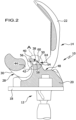
- FIG. 1 A first embodiment of a joint endoprosthesis 10 is shown schematically as an example.
- the joint endoprosthesis 10 comprises a first joint endoprosthesis component 12 and a second joint endoprosthesis component 14 which interacts with the first joint endoprosthesis component to form a movement joint.
- Figure 1 The illustrated embodiment of the joint endoprosthesis 10 is designed in the form of an artificial knee joint 16.
- the first joint endoprosthesis component 12 comprises a tibial component 18 that can be fixed to a patient's tibia and a meniscus component 20 arranged thereon.
- the second joint endoprosthesis component 14 is designed in the form of a femoral component 22 that can be fixed to a femur.
- the first joint endoprosthesis component 12 comprises a first articular surface 24 in the form of a sliding surface 26 formed on the meniscus component 20, which rests against a corresponding second articular surface 28, which is formed by two spatially separated condylar surfaces 30 of the femoral component 22.
- the first and second articular surfaces 24, 28 form a cooperating sliding pair.
- the articular surfaces 24 and 28 are designed to slide and/or roll against each other.
- joint endoprosthesis 10 After implantation, the joint endoprosthesis 10 is enclosed by a joint capsule 66 which is filled with synovial fluid 70.
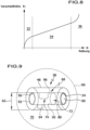
- Figure 8 shows an example of the progression of wear in the three phases shown.
- the wear begins with a running-in area 32, in which a later profile of the interacting sliding partners is formed.
- the stationary region 34 is also the so-called operating region of a friction pairing, since it is based on a known behavior.
- a failure area 36 is connected to the stationary area. This is where a failure of the friction pairing occurs.
- the failure can occur, for example, when a permissible level of wear h is exceeded. It is also conceivable that one or more of the interacting partners of the friction pairing could be destroyed.
- the joint endoprosthesis 10 namely the first joint endoprosthesis component 12, comprises a medical joint wear collection device implant 38. It is in the embodiment of the Figures 1 and 2 arranged or formed on the first joint endoprosthesis component 12 in a region of low mechanical stress.
- the joint wear collection device implant 38 is arranged or formed on the meniscus component 20 encompassed by the first joint endoprosthesis component 12, specifically on a stop 40 which protrudes from the meniscus component 20 in the direction of the femoral component 22 and which has a stop surface 42 pointing in the posterior direction for a connecting section 44 on the femoral component 22, which connecting section 44 connects two condyles 46 which encompass the condylar surfaces 30.
- the connecting section 44 and the stop 40 prevent movement of the femoral component 22 relative to the meniscus component 20 in the anterior direction, in particular when the knee joint 16 is bent.
- the joint wear collection device implant 38 is enclosed by the meniscus component 20 and thus comprises an implant body 48 which is formed by the meniscus component 20 itself, thus by the first joint endoprosthesis component 12.
- a collecting space 50 is formed on the implant body 48 for receiving particles, in particular the described abrasion particles, which are released into the synovial fluid 70 contained in the joint capsule 66 of the movement joint by abrasion on the first joint endoprosthesis component 12.
- the collection chamber 50 comprises a collection chamber inlet 54 and a collection chamber outlet 56. Except for the collection chamber inlet 54 and the collection chamber outlet 56, the collection chamber 50 is delimited by a fluid-tight, closed collection chamber boundary surface 58.
- the plenum inlet 54 defines a plenum inlet cross-sectional area. This has the Figures 1 and 2 illustrated embodiment has a value in a range from about 1 mm 2 to about 40 mm 2 . In particular, the value of the plenum inlet cross-sectional area is in a range from about 2 mm 2 to about 10 mm 2 .
- the collecting space outlet 56 defines a collecting space outlet cross-sectional area in an analogous manner.
- the value of the collecting space outlet cross-sectional area in the exemplary embodiment is in particular in a range from about 2 mm 2 to about 10 mm 2 .
- the collecting chamber 50 is hollow-cylindrical or essentially hollow-cylindrical. It is designed in the form of a bore 60 passing through the joint wear collecting device implant 38.
- the collecting chamber 50 has in the Figures 1 and 2 illustrated embodiment has a diameter in a range of about 2 mm to about 7 mm.
- the diameter 62 is in a range of about 3 mm to about 5 mm.
- the joint wear collection device implant 38 and thus the collection chamber 50, is arranged or designed in the joint endoprosthesis 10 in such a way that the synovial fluid 70 can flow through it as a result of a movement of the joint.
- a flow direction is symbolized by the arrow 64.
- a synovial fluid flow is generated in the direction of the arrow 64, which flows into the collection chamber 50 through the collection chamber inlet 54 and out of it again through the collection chamber outlet 56.
- a unidirectional flow through the collecting space 50 is shown schematically.
- the flow through the collecting space 50 with synovial fluid 70 can also be bidirectional.
- Figure 9 shows another embodiment of a joint wear collection device implant 38. It is designed as a stand-alone implant to be inserted into a joint capsule 66 of a Figure 9 to be implanted in a movement joint that is not shown for clarity.
- the joint wear collection device implant 38 comprises an implant body 48 on which a collection chamber 50 is formed.
- a collection chamber 50 is formed.
- the same reference numerals are used for identical or functionally similar parts or components of the joint wear collection device implant 38 as in the embodiment of the Figures 1 and 2 used.
- the implant body 48 is essentially cylindrical.
- the collecting chamber 50 is hollow cylindrical with a diameter of 62.
- the joint wear collection device implant 38 includes a particle extraction device 68 for extracting particles 52 from the synovial fluid 70 contained in the joint capsule 66.
- the particle extraction device 68 is arranged or formed in the collecting space 50.
- the particle extraction device 68 comprises a filter device 72 and a fluid-mechanical separation device 74.
- the structure of the separator 74 is shown schematically in Figure 3 presented in more detail in the form of a first embodiment.
- a plurality of deflection elements 76 of the separation device 74 are arranged in the collection chamber 50. They serve the purpose of forming separation regions 78 in which a flow velocity of the synovial fluid 70 through the collection chamber 50 is zero or essentially zero.
- the deflection elements 76 are designed in the form of projections 80.
- the projections 80 are designed in the form of ring projections that protrude from the collection chamber boundary surface 58.
- a circular opening 82 is formed on each of the deflection elements 76.
- a diameter 84 of the openings 82 has a value that is slightly less than a third of the diameter 62.
- the openings 82 are formed coaxially to a longitudinal axis 86 of the collecting space 50.
- the separation areas 78 also referred to as so-called dead water zones, form between adjacent deflection elements 76 near the collection space boundary surface 58.
- Figure 4 shows an alternative embodiment of a separating device 74 in the collecting chamber 50 of a joint wear collecting device implant 38.
- several deflection elements 76 in the form of projections 80 are arranged in the collecting chamber 50.
- there is no continuous, straight flow channel as in the embodiment of the Figure 3 which is defined by the openings 82 in the deflection elements 76 formed coaxially to the longitudinal axis 86.
- two projections 80 are arranged in such a way that a straight flow through openings 82 on projections 80, as in the embodiment at Figure 3 are provided.
- Synovial fluid 70 is deflected at the projections 80, which are arranged in a space between two ring projections to prevent direct flow through the openings 82.
- Particles 52 are therefore deflected at the central projections 80 and can thus reach separation areas 78 near the collection space boundary surface 58 and the ring projections. In these separation areas 78, the flow velocity of the synovial fluid 70 in the collection space 50 is zero or essentially zero.
- the particles 52 are enriched in the separation areas 78 and can thus no longer escape from the collection space 50.
- the filter device 72 comprises one or more filter elements 88.
- the filter elements 88 are designed to retain particles 52, in particular abrasion particles.
- Figure 5 schematically shows an embodiment of a joint wear collection device implant 38 with a filter device 72 which comprises a plurality of filter elements 88.
- the filter elements 88 have a pore size in a range of about 5 ⁇ m ECD (Equivalent Circular Diameter) to about 100 ⁇ m ECD.
- the multiple filter elements 88 differ in the embodiment of the Figure 5 by their respective pore size.
- several filter elements 88 are arranged or formed one after the other between the collecting chamber inlet 54 and the collecting chamber outlet 56, with the pore sizes of the filter elements 88 arranged one after the other decreasing starting from the collecting chamber inlet 54.
- both the collecting chamber inlet 54 with a collecting chamber inlet closure element 90 and the collecting chamber outlet 56 with a Collecting chamber outlet closure element 92 must be closed.
- the two locking elements 90 and 92 are each shown in dashed lines.
- the collection chamber inlet closure element 90 and the collection chamber outlet closure element 92 are made of a closure element material which is soluble or detachable in the synovial fluid 70. This makes it possible in particular to implant the joint wear collection device implant 38 in the joint capsule 66, with the collection chamber inlet 54 and the collection chamber outlet 56 being closed by the collection chamber inlet closure element 90 or the collection chamber outlet closure element 92. This prevents blood or larger tissue parts from clogging and blocking the collection chamber 50. Only after a certain time do the closure elements 90 or 92 dissolve completely, thus allowing the synovial fluid 70 to flow into the collection chamber 50.
- Surfaces of the deflection elements 76 can in particular have a particle retention structure not shown in the figures or can carry or comprise one or more particle retention elements. In this way, particles 52 can also adhere to a surface of the deflection elements 76 and possibly even form chemical bonds in order to prevent the particles 52 from escaping from the collection space 50.
- the separation device 74 with the deflection elements 76 is designed in the form of an inertial or deflection separation device.
- the deflection elements 76 are formed in one piece, in particular monolithically, with the implant body 48. They can in particular be formed from a material which corresponds to the material forming the implant body 48.
- the filter elements 88 are made of a filter element material.
- the implant body 48 and thus an essential component of the joint wear collection device implant 38 is made of a joint wear collection device implant material.
- the joint wear collection device implant material and the filter element material are made of different materials.
- the implant body 48 can thus be made with sufficient stability. In particular, it can be made of the joint endoprosthesis component 12 itself, as described.
- the filter elements 88 of the filter device 72 can thus be made of materials that have optimized filter properties.
- the filter element material can be a fabric. In this way, different pore sizes can also be easily realized in filter elements.
- the joint wear collection device implant material can in particular be a plastic and/or a metallic material.
- the joint wear collection device implant 38 may optionally comprise an active substance container 94. This is exemplified in Figure 9 shown in dotted lines.
- the active substance container 94 can optionally be filled with a medical and/or pharmaceutical active substance, for example an anti-inflammatory active substance.
- the active substance container 94 is fluidically connected to the collection chamber 50, so that the active substance contained in the active substance container 94 can be gradually released into the synovial fluid 70 flowing through the collection chamber 50.
- an inner surface 96 of the collecting chamber 50 is optionally provided with a coating (not shown in the figures) for chemically and/or electrostatically binding particles 52.
- a coating can further improve adhesion and thus permanent retention of particles 52 in the collection chamber 50.
- the joint wear collection device implant 38 which is shown separately as an example, can, as already explained, also be integrated into the first joint endoprosthesis component 12, as is the case in embodiments 1 and 2.
- the structure of the collection chamber 50 including a particle extraction device 68 can also be used in the embodiment of the Figures 1 and 2 as above in connection with the Figures 3 to 5 and 9 explained.
- the joint wear collection device implant 38 is arranged or formed on the first joint endoprosthesis component 12 spatially separated from the first joint surface 24.
- the collection chamber inlet 54 nor the collection chamber outlet 56 are arranged or formed on the first joint surface 24.
- the collecting chamber inlet 54 and the collecting chamber outlet 56 are arranged or formed outside the first articular surface 24 or separately therefrom.
- the joint endoprosthesis component 12 is made of a plastic and/or a metal.
- the joint wear collection device implant 38 is in the Figure 9 illustrated embodiment is formed by a generative manufacturing process, namely either by 3D printing or by selective laser sintering, depending on whether the implant body 48 and the deposition device 74 are made of a plastic or a metallic material.
- the first joint endoprosthesis component 12 is in the Figure 1 and 2
- the exemplary embodiment shown is made of a plastic and a metal.
- the meniscus component 20 is made of a plastic
- the tibial component 18 is made of a metal.
- the first joint endoprosthesis component 12 or its components can also be formed by a generative manufacturing process. In particular, this is possible by means of 3D printing or selective laser sintering.
- the design of the medical joint wear collection device implant 38 is not limited to structural designs such as those in particular in connection with the Figures 1 to 5 and 9 Rather, such joint wear collection device implants 38 can also be provided in other joint endoprostheses 10, for example in artificial hip joints, shoulder joints, ankle joints, wrist joints, elbow joints or intervertebral disc joints.
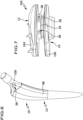
- Figure 6 shows an example of an embodiment of a hip stem 98 of an artificial hip joint, on which a joint wear collection device implant 38 is arranged or formed in the region of a neck 100.
- a joint wear collection device implant 38 is arranged or formed in the region of a neck 100.
- it comprises a bore 60 for forming the collection space 50.
- An embodiment of an intervertebral disc joint 102 is shown schematically in Figure 7. It comprises two contact elements 104 and 106 for contact with adjacent vertebral bodies.
- the contact elements 104 and 106 form first and second joint endoprosthesis components 12 and 14 with first and second interacting articular surfaces 24 and 28.
- Two joint wear collection device implants 38 are provided, which are arranged or formed on the first joint endoprosthesis component 12, namely on the contact element 104.
- the specific design of the joint wear collection device implants 38 in the embodiments of the Figures 6 and 7 is realized in accordance with the embodiments of joint wear collection device implants 38 already described above, so that reference can be made to the above description.
- joint wear collection device implants 38 it is possible to extract particles 52, in particular wear particles from first and/or joint surfaces 24, 28 of first and second joint endoprosthesis components 12, 14, from the synovial fluid 70 contained in the joint capsule 66 and to permanently retain them in the collection space 50. In this way, any rejection reactions in the body of a patient can be reliably and permanently avoided.
Landscapes
- Health & Medical Sciences (AREA)
- Orthopedic Medicine & Surgery (AREA)
- Engineering & Computer Science (AREA)
- Biomedical Technology (AREA)
- Heart & Thoracic Surgery (AREA)
- Cardiology (AREA)
- Oral & Maxillofacial Surgery (AREA)
- Transplantation (AREA)
- Vascular Medicine (AREA)
- Life Sciences & Earth Sciences (AREA)
- Animal Behavior & Ethology (AREA)
- General Health & Medical Sciences (AREA)
- Public Health (AREA)
- Veterinary Medicine (AREA)
- Neurology (AREA)
- Physical Education & Sports Medicine (AREA)
- Prostheses (AREA)
Applications Claiming Priority (1)
| Application Number | Priority Date | Filing Date | Title |
|---|---|---|---|
| DE102022132066.9A DE102022132066A1 (de) | 2022-12-02 | 2022-12-02 | Medizinisches Gelenkabriebsammelvorrichtungsimplantat, Gelenkendoprothesenkomponente und Gelenkendoprothese |
Publications (1)
| Publication Number | Publication Date |
|---|---|
| EP4378427A1 true EP4378427A1 (fr) | 2024-06-05 |
Family
ID=89073074
Family Applications (1)
| Application Number | Title | Priority Date | Filing Date |
|---|---|---|---|
| EP23213627.5A Pending EP4378427A1 (fr) | 2022-12-02 | 2023-12-01 | Implant médicale de collecte des débris d'abrasion d'articulation , composant d'endoprothèse d'articulation et endoprothèse d'articulation |
Country Status (2)
| Country | Link |
|---|---|
| EP (1) | EP4378427A1 (fr) |
| DE (1) | DE102022132066A1 (fr) |
Citations (5)
| Publication number | Priority date | Publication date | Assignee | Title |
|---|---|---|---|---|
| US5378228A (en) * | 1991-12-16 | 1995-01-03 | Schmalzried; Thomas P. | Method and apparatus for joint fluid decompression and filtration with particulate debris collection |
| US5879406A (en) * | 1997-07-15 | 1999-03-09 | Saint-Gobain Industrial Ceramics, Inc. | Artificial joint bioprosthesis for mitigation of wear |
| US20050055101A1 (en) * | 2001-12-11 | 2005-03-10 | Dimitrios Sifneos | Endoprosthesis of the knee and/or other joints |
| US20110276146A1 (en) * | 2009-02-19 | 2011-11-10 | David Segal | Prosthetic implant device comprising a sealing arrangement and a chamber adapted to receive debris particles |
| US20210338440A1 (en) * | 2020-04-30 | 2021-11-04 | DePuy Synthes Products, Inc. | Orthopaedic knee implant system with controlled stiffness |
Family Cites Families (1)
| Publication number | Priority date | Publication date | Assignee | Title |
|---|---|---|---|---|
| GB2381753B (en) * | 2001-11-07 | 2005-04-06 | Michael Thomas Clarke | Improvements to joint prostheses |
-
2022
- 2022-12-02 DE DE102022132066.9A patent/DE102022132066A1/de active Pending
-
2023
- 2023-12-01 EP EP23213627.5A patent/EP4378427A1/fr active Pending
Patent Citations (5)
| Publication number | Priority date | Publication date | Assignee | Title |
|---|---|---|---|---|
| US5378228A (en) * | 1991-12-16 | 1995-01-03 | Schmalzried; Thomas P. | Method and apparatus for joint fluid decompression and filtration with particulate debris collection |
| US5879406A (en) * | 1997-07-15 | 1999-03-09 | Saint-Gobain Industrial Ceramics, Inc. | Artificial joint bioprosthesis for mitigation of wear |
| US20050055101A1 (en) * | 2001-12-11 | 2005-03-10 | Dimitrios Sifneos | Endoprosthesis of the knee and/or other joints |
| US20110276146A1 (en) * | 2009-02-19 | 2011-11-10 | David Segal | Prosthetic implant device comprising a sealing arrangement and a chamber adapted to receive debris particles |
| US20210338440A1 (en) * | 2020-04-30 | 2021-11-04 | DePuy Synthes Products, Inc. | Orthopaedic knee implant system with controlled stiffness |
Also Published As
| Publication number | Publication date |
|---|---|
| DE102022132066A1 (de) | 2024-06-13 |
Similar Documents
| Publication | Publication Date | Title |
|---|---|---|
| EP0244720B1 (fr) | Implants chirurgicaux ou orthopédiques avec cavités contenant des substances médicinales | |
| EP0928172B1 (fr) | Prothese d'articulation du genou sans tige | |
| DE69532086T2 (de) | Ventilanordnung zum verringern von synovialem flüssigkeitsdruck | |
| DE60306873T2 (de) | System zur Wiederherstellung der Oberfläche einer Tibia | |
| EP0329019B1 (fr) | Coque acétabulaire pour une prothèse d'articulation | |
| DE4039064C2 (fr) | ||
| EP3763335B1 (fr) | Implant articulaire pour une administration d'un médicament | |
| AT390183B (de) | Knochenimplantat fuer endoprothesen | |
| EP0745352A2 (fr) | Râpe intramédullaire | |
| EP3542760B1 (fr) | Système d'espaceur du genou pourvu de dispositif de rinçage | |
| DE60318156T2 (de) | Werkzeug zum Vorbereiten einer Knochenhöhle für Arthroplastie | |
| DE69428205T2 (de) | Instrument zum lösen und durchschneiden der intima eines blutgefässes | |
| DE60212881T2 (de) | Biologisch abbaubare aurikuläre prothesen | |
| EP0205512A1 (fr) | Tampon en materiau chirurgical. | |
| DE2747568A1 (de) | Vorrichtung fuer kreuzbandplastik am kniegelenk des menscheen | |
| DE3736304A1 (de) | Oberschenkelteil fuer eine hueftgelenkendoprothese | |
| DE4323873C2 (de) | Hohlschaftraspel | |
| EP4378427A1 (fr) | Implant médicale de collecte des débris d'abrasion d'articulation , composant d'endoprothèse d'articulation et endoprothèse d'articulation | |
| EP3493771B1 (fr) | Cuvette acétabulaire et endoprothèse d'articulation | |
| EP1649834A1 (fr) | Logement intramusculaire sous-cutané pour implant transcutané fixe | |
| DE4332230C2 (de) | Endoprothese, insbesondere Hüftendoprothese | |
| DE10353400B4 (de) | Subkutanes, intramuskuläres Lager für ein starres transkutanes Implantat | |
| DE9319132U1 (de) | Markraumsperre | |
| EP4124356B1 (fr) | Dispositif et procédé d'application d'un fluide pharmaceutique | |
| EP4385462B1 (fr) | Système d'implant d'échantillon modulaire |
Legal Events
| Date | Code | Title | Description |
|---|---|---|---|
| PUAI | Public reference made under article 153(3) epc to a published international application that has entered the european phase |
Free format text: ORIGINAL CODE: 0009012 |
|
| STAA | Information on the status of an ep patent application or granted ep patent |
Free format text: STATUS: THE APPLICATION HAS BEEN PUBLISHED |
|
| AK | Designated contracting states |
Kind code of ref document: A1 Designated state(s): AL AT BE BG CH CY CZ DE DK EE ES FI FR GB GR HR HU IE IS IT LI LT LU LV MC ME MK MT NL NO PL PT RO RS SE SI SK SM TR |
|
| STAA | Information on the status of an ep patent application or granted ep patent |
Free format text: STATUS: REQUEST FOR EXAMINATION WAS MADE |
|
| 17P | Request for examination filed |
Effective date: 20241204 |
|
| RBV | Designated contracting states (corrected) |
Designated state(s): AL AT BE BG CH CY CZ DE DK EE ES FI FR GB GR HR HU IE IS IT LI LT LU LV MC ME MK MT NL NO PL PT RO RS SE SI SK SM TR |
|
| STAA | Information on the status of an ep patent application or granted ep patent |
Free format text: STATUS: EXAMINATION IS IN PROGRESS |
|
| 17Q | First examination report despatched |
Effective date: 20250722 |