EP4378583A1 - Substrat d'échantillon, appareil d'analyse d'échantillon liquide et procédé de réparation d'échantillons liquides, en particulier pour une analyse lc-ms - Google Patents
Substrat d'échantillon, appareil d'analyse d'échantillon liquide et procédé de réparation d'échantillons liquides, en particulier pour une analyse lc-ms Download PDFInfo
- Publication number
- EP4378583A1 EP4378583A1 EP22211050.4A EP22211050A EP4378583A1 EP 4378583 A1 EP4378583 A1 EP 4378583A1 EP 22211050 A EP22211050 A EP 22211050A EP 4378583 A1 EP4378583 A1 EP 4378583A1
- Authority
- EP
- European Patent Office
- Prior art keywords
- sample
- vessel
- vessels
- coupling section
- coupling
- Prior art date
- Legal status (The legal status is an assumption and is not a legal conclusion. Google has not performed a legal analysis and makes no representation as to the accuracy of the status listed.)
- Pending
Links
Images


Classifications
-
- B—PERFORMING OPERATIONS; TRANSPORTING
- B01—PHYSICAL OR CHEMICAL PROCESSES OR APPARATUS IN GENERAL
- B01L—CHEMICAL OR PHYSICAL LABORATORY APPARATUS FOR GENERAL USE
- B01L3/00—Containers or dishes for laboratory use, e.g. laboratory glassware; Droppers
- B01L3/56—Labware specially adapted for transferring fluids
- B01L3/563—Joints or fittings; Separable fluid transfer means to transfer fluids between at least two containers, e.g. connectors
- B01L3/5635—Joints or fittings; Separable fluid transfer means to transfer fluids between at least two containers, e.g. connectors connecting two containers face to face, e.g. comprising a filter
-
- B—PERFORMING OPERATIONS; TRANSPORTING
- B01—PHYSICAL OR CHEMICAL PROCESSES OR APPARATUS IN GENERAL
- B01L—CHEMICAL OR PHYSICAL LABORATORY APPARATUS FOR GENERAL USE
- B01L3/00—Containers or dishes for laboratory use, e.g. laboratory glassware; Droppers
- B01L3/50—Containers for the purpose of retaining a material to be analysed, e.g. test tubes
- B01L3/508—Rigid containers without fluid transport within
- B01L3/5085—Rigid containers without fluid transport within for multiple samples, e.g. microtitration plates
-
- B—PERFORMING OPERATIONS; TRANSPORTING
- B01—PHYSICAL OR CHEMICAL PROCESSES OR APPARATUS IN GENERAL
- B01L—CHEMICAL OR PHYSICAL LABORATORY APPARATUS FOR GENERAL USE
- B01L3/00—Containers or dishes for laboratory use, e.g. laboratory glassware; Droppers
- B01L3/56—Labware specially adapted for transferring fluids
- B01L3/563—Joints or fittings; Separable fluid transfer means to transfer fluids between at least two containers, e.g. connectors
-
- B—PERFORMING OPERATIONS; TRANSPORTING
- B01—PHYSICAL OR CHEMICAL PROCESSES OR APPARATUS IN GENERAL
- B01L—CHEMICAL OR PHYSICAL LABORATORY APPARATUS FOR GENERAL USE
- B01L2200/00—Solutions for specific problems relating to chemical or physical laboratory apparatus
- B01L2200/02—Adapting objects or devices to another
- B01L2200/025—Align devices or objects to ensure defined positions relative to each other
-
- B—PERFORMING OPERATIONS; TRANSPORTING
- B01—PHYSICAL OR CHEMICAL PROCESSES OR APPARATUS IN GENERAL
- B01L—CHEMICAL OR PHYSICAL LABORATORY APPARATUS FOR GENERAL USE
- B01L2200/00—Solutions for specific problems relating to chemical or physical laboratory apparatus
- B01L2200/02—Adapting objects or devices to another
- B01L2200/026—Fluid interfacing between devices or objects, e.g. connectors, inlet details
-
- B—PERFORMING OPERATIONS; TRANSPORTING
- B01—PHYSICAL OR CHEMICAL PROCESSES OR APPARATUS IN GENERAL
- B01L—CHEMICAL OR PHYSICAL LABORATORY APPARATUS FOR GENERAL USE
- B01L2300/00—Additional constructional details
- B01L2300/08—Geometry, shape and general structure
- B01L2300/0809—Geometry, shape and general structure rectangular shaped
- B01L2300/0819—Microarrays; Biochips
-
- B—PERFORMING OPERATIONS; TRANSPORTING
- B01—PHYSICAL OR CHEMICAL PROCESSES OR APPARATUS IN GENERAL
- B01L—CHEMICAL OR PHYSICAL LABORATORY APPARATUS FOR GENERAL USE
- B01L2300/00—Additional constructional details
- B01L2300/08—Geometry, shape and general structure
- B01L2300/0809—Geometry, shape and general structure rectangular shaped
- B01L2300/0822—Slides
-
- B—PERFORMING OPERATIONS; TRANSPORTING
- B01—PHYSICAL OR CHEMICAL PROCESSES OR APPARATUS IN GENERAL
- B01L—CHEMICAL OR PHYSICAL LABORATORY APPARATUS FOR GENERAL USE
- B01L2300/00—Additional constructional details
- B01L2300/08—Geometry, shape and general structure
- B01L2300/0809—Geometry, shape and general structure rectangular shaped
- B01L2300/0829—Multi-well plates; Microtitration plates
Definitions
- the present invention relates to a sample substrate, a liquid sample analyzing apparatus, and a method for preparing liquid samples, in particular for a LC-MS (liquid chromatography mass spectrometry) analysis.
- Applications of the invention are available, e.g., in the field of processing of liquid samples, in particular biological samples, e. g. in proteomics investigations.
- the latter has advantages in terms of the capability of detecting a large number of proteins per cell with high specificity.
- LC-MS generally includes the following procedure.
- Biological cells are isolated, e. g. with a fluorescence-activated cell sorter (FACS), and subjected to cell lysis for providing proteins included in the cells.
- the proteins are enzymatically digested into peptides fragments.
- these fragments typically are labelled with labelling molecules, like e. g. tandem mass tag (TMT) labels, serving as mass reporters, optionally followed by label quenching (removing unbound labelling molecules).
- labelling molecules like e. g. tandem mass tag (TMT) labels, serving as mass reporters, optionally followed by label quenching (removing unbound labelling molecules).
- the peptide fragments are introduced into a tandem mass spectrometer and identified by peptide fingerprinting or tandem mass spectrometry, using bioinformatics techniques.
- the sample preparation steps from isolating the cells to pooling may be challenging in terms of parallel handling large numbers of samples included in small liquid quantities, keeping the assignment of the peptide fragments to certain samples and avoiding cross-contamination between different samples.
- a sample preparing apparatus for preparing liquid samples for a sample analysis is disclosed in [6], wherein a carrier plate device with an array of reaction sites is combined with a collection device having collection vessels. Each collection vessel is adapted for collecting the liquid samples from at least two of the reaction sites and for providing the liquid samples for the sample analysis.
- Adapting a collection device for positioning directly in a carousel of an autosampler apparatus, like a liquid chromatography autosampler apparatus, is described in [7].
- a 384-well plate is adapted for handling relatively large volumes in a range up to 100 ⁇ l. Furthermore, the substrates require complex lid handling for minimizing evaporation.
- transferring the labelled fragments from the wells to the glass HPLC insert or any other common collection vessel is time consuming, includes a risk of introducing contaminations and is prone to errors.
- time-consuming pipetting one by one is used for the transferring task.
- the patterned glass slides are specialized devices which are not adapted to all steps of the process chain, including further preceding sample handling steps, like cell isolation.
- the layer stack used in [4] has a complex and costly structure.
- [6] and [7] introduced some improvements in terms of sample pooling and transferring samples to a liquid chromatography autosampler apparatus, there are still limitations in the LC-MS analysis.
- the conventional techniques are not sufficiently adapted for an automation of sample preparation, resulting in limitations in terms of time consuming processes with human interaction and the risk of contaminations.
- one significant particular disadvantage of the conventional techniques is that prepared samples have to be transferred manually to sample cartridges for executing an LC-MS sample analysis.
- Evotips ® see, e.g., [5]
- the loading step of the sample prepared by any sample preparation method onto the Evotips ® always include a time-consuming pipetting step.
- the sample comes in contact with the walls of a pipette tip that may result in adsorptive losses of some of the peptides from the sample to be analyzed.
- the objectives of the invention are to provide an improved sample substrate, liquid sample analyzing apparatus, and method for preparing liquid samples, in particular for a LC-MS, being capable of avoiding disadvantages or limitations of conventional techniques.
- sample preparation is to be provided with a capability of facilitating multiplexing the sample preparation and analysis, decreasing operation time, handling reduced sample volumes down to the nanolitre (nl) range, minimizing or avoiding the evaporation problem, and/or facilitating the sample pooling.
- the sample substrate is to be configured as user-friendly as possible and/or adapted for the whole process chain of a sample preparation, in particular LC-MS analysis, e. g., allowing an automation of the sample preparation.
- a sample substrate being adapted for preparing samples for an LC-MS analysis (e.g., a proteomics mass spectrometry analysis).
- the sample substrate comprises a reaction substrate device having a plurality of vessels (e.g., wells or more complex receptacles or arrays of accommodating spaces).
- Each vessel (of the plurality of vessels) has at least one accommodating space (or: sub-vessel, sub-well) being configured for accommodating a liquid sample, preferably a sample droplet.
- Each vessel further has a vessel coupling section with a vessel opening.
- the sample substrate further comprises a plurality of collection cartridges.
- Each collection cartridge (of the plurality of collection cartridges) has a cartridge coupling section with a cartridge opening.
- Each collection cartridge is configured for accommodating the liquid sample from one of the vessels.
- Each of the collection cartridges preferably has a shape of a pipette tip and/or conus and/or a column shape, in particular with a single opening (namely the cartridge opening) at an end face.
- the collection cartridges are commercially available Evotips ® (see, e.g., [5]) or cartridges with a shape matched to Evotips ® .
- Evotips ® are disposable trap columns that speed up sample loading and significantly reduce carry-over, resulting in simplified workflows as integrating elution with liquid chromatography removes several sample handling steps as well as reduces injection cycle overheads.
- the collection cartridges are integral components.
- the cartridge coupling section preferably is an integral part of the remaining collection cartridge.
- the collection cartridges are made of multiple parts, e.g. a cartridge body and the cartridge coupling section fixed to the cartridge body.
- the collection cartridges are tip shaped containers, particularly preferred made of an inert polymer material, like e.g. a C18 material, which typically has polymeric non-polar endcapping and a high carbon content, as it is known e.g. for obtaining advantages for desalting/cleaning a protein digest sample before injection into a chromatographic separation column.
- an inert polymer material like e.g. a C18 material, which typically has polymeric non-polar endcapping and a high carbon content, as it is known e.g. for obtaining advantages for desalting/cleaning a protein digest sample before injection into a chromatographic separation column.
- each vessel coupling section is matched to each cartridge coupling section with form-fitting so that they are adapted for (in particular liquid tight) coupling the reaction substrate device and the plurality of collection cartridges, thereby providing direct liquid communication of the vessels and the collection cartridges via the openings thereof.
- each vessel coupling section and each cartridge coupling section are adapted for a direct mutual coupling.
- a contact area of the vessel coupling section and the cartridge coupling section in contact with each other has a round, in particular circular or elliptic cross-section shape.
- the sample substrate enables 1-to-1 coupling of the vessels and the collection cartridges.
- the sample substrate is adapted for enabling (individual) coupling of (exactly) one of the vessels and (exactly) one of the collection cartridges, particularly via the respective vessel coupling section and cartridge coupling section.
- the coupling provides direct liquid communication between (exactly) one of the vessels and (exactly) one of the collection cartridges.
- One or multiple sample(s) prepared in one of the vessels can therefore only be transferred in only one of the collection cartridges.
- Coupled section generally refers to a topographic structural feature (or element) providing an exposed engagement shape, in particular with an inherent liquid tightness, when coupled with another coupling section with complementary shape.
- Each coupling section of the reaction substrate device in particular an open end portion of one the vessels providing the vessel opening, matches with a coupling section, in particular an open end portion of one of the collection cartridges providing the cartridge opening.
- the coupling sections additionally provide a mechanical connection of the vessels and the collections cartridges, even during sample transfer, e. g. by centrifugation.
- the mechanical connection of the vessels and the collections cartridges can be further supported by the design of a centrifugation device, holding the vessels and the collections cartridges together, and/or by fixing elements providing an additional clamping and/or screwing connection between the vessels and the collections cartridges in the coupled state thereof.
- a liquid sample analyzing apparatus being adapted for preparing samples for a LC-MS sample analysis (e.g., a proteomics mass spectrometry analysis) and executing the LC-MS sample analysis, comprising a sample substrate according to the first general aspect of the invention or an embodiment thereof, and an LC-MS apparatus.
- a LC-MS sample analysis e.g., a proteomics mass spectrometry analysis
- the above objective is solved by a method of executing an LC-MS sample analysis (e.g., a proteomics mass spectrometry analysis), wherein a sample substrate according to the first general aspect of the invention or an embodiment thereof and an LC-MS apparatus are employed.
- the method comprises collecting samples to be analyzed in the vessels of the sample substrate, subjecting the (collected) samples to a decomposition reaction in the vessels, and coupling each of the collection cartridges with one of the vessels (preferably after subjecting the samples).
- the method further comprises transferring (e.g., pooling) the decomposed samples from each of the vessels to the coupled collection cartridges, decoupling the collection cartridges from the vessels and then coupling the collection cartridges with the LC-MS apparatus, and conducting the LC-MS sample analysis with the LC-MS apparatus.
- transferring e.g., pooling
- the sample substrate may be arranged in two different positions (orientations relative to gravity).
- the reaction substrate device when collecting the samples, subjecting the samples to decomposition reaction and coupling the collection cartridges to the vessels, the reaction substrate device is arranged in a first position, wherein the vessels are arranged on a top side of the reaction substrate device and/or the vessel openings are oriented upwards, i.e. facing in a direction opposite to direction of gravity.
- the sample substrate is arranged in a second position, wherein the vessels are arranged on a lower side of the reaction substrate device and/or the vessel openings are oriented downwards, i.e. facing in the direction of gravity.
- the sample substrate is moved from the first to the second position by turning the sample substrate upside down.
- the decomposed samples are enabled to flow from the vessels to the (coupled) collection cartridges by the effect of gravity.
- this sample transfer is further supported by centrifugation.
- the samples to be prepared and analyzed using the sample substrate comprise biological material, in particular biological cells, cell groups and/or cell components.
- biological material can be one single cell, multiple cells or at least one piece of biological material originating from tissue slices (such as fresh frozen tissue or paraffin embedded FTPE tissue slices).
- the decomposition reaction preferably comprises cell lysis and/or protein digestion.
- reagents are added that will allow cell lysis and protein digestion into peptide fragments.
- the sample substrate can be used to perform all the steps of a sample preparation protocol before the subsequent analysis can be undertaken by LC-MS methods (mass spectrometry).
- the sample substrate allows a direct and preferably automatic transfer (e.g., pooling) of the samples prepared in the vessels to the collection cartridges, such as Evotips ® , thereby excluding from the workflow the use of additional auxiliary transfer pipettes and/or pipetting steps to undertake the transfer of the prepared sample before their introduction to the analysis device, in particular the LC-MS apparatus. Eliminating pipetting steps will result in reduced peptide losses that normally occurs on the walls of the transfer pipettes.
- single or low amount cell (e.g., protein) samples prepared for single cell proteomic analyses wherein sample sizes are generally already low (usually ⁇ ng)
- employing the sample substrate according to the present invention offers an increased number of proteins detected from each sample.
- sample volumes used for sample preparation (sample reactions) in the vessels can be reduced depending on the application conditions, down to samples with a volume below 1 ⁇ l, in particular below 100 nl, down to, e.g., 1 nl or even below.
- sample volumes can be increased by a step of dilution before a transfer via centrifugation to be e.g. 1 ⁇ l to 10 ⁇ l ("transferred volume").
- transferred volume The size of the vessels can be reduced, thus facilitating the handling of the sample substrate and facilitating measures against evaporation.
- the multiplexing of the sample preparation is supported.
- the sample substrate can be easily manufactured, e.g., from a low-cost plastics material, and/or can be provided and used as a single-use or reusable consumable.
- the application of the invention is possible for preparing the plurality of liquid samples for various types of sample analyses.
- multiple single cell, multiple cells and/or cell components can be arranged at each of the reactions vessels.
- the samples can be prepared, e.g., for a subsequent mass spectrometry, optionally combined with a liquid chromatographic separation of sample components, and/or for another analysis, e.g., a genomic analysis, including a sequencing measurement.
- sample substrate according to present invention can be incorporated in various sample collection apparatuses to reduce the number of manual operation required and improve the quality/sensitivity of, e.g., proteomics mass spectrometry results.
- sample substrate may be used in association with the sample collection apparatus (also called proteo-CHIP) disclosed in [7].
- the vessels may be arranged in a matrix and/or array, wherein the vessels are spaced apart from each other.
- the number of vessels and the type of arrangement can be selected in dependency on the degree of parallelism of sample handling to be obtained, e.g., in dependency on the number of different labeling molecules to be applied.
- the shape of the reactions vessel can be selected in dependency on, e.g., application conditions of the sample preparing apparatus and the applied sample liquid handling technique.
- each cartridge coupling section is matched to a shape of a sample input section of an LC-MS apparatus.
- the collection cartridges can be removed from the reaction substrate device after the samples have been transferred from the vessels to the collection cartridges, and directly placed into the LC-MS apparatus without the necessity of further transferring the samples into other vessels to execute the LC-MS analysis.
- the Evotips ® enable direct interfacing with an Evosep ® Liquid Chromatography system for mass spectroscopy analysis.
- one of the vessel coupling section and the cartridge coupling section is formed by a protruding rim at the vessel opening of the vessel or the cartridge opening of the collection cartridge, resp., and the other one of the vessel coupling section and the cartridge coupling section is provided by an inner wall section at the vessel opening or the cartridge opening, resp..
- the protruding rim and the inner wall section are in direct contact, e.g., wherein the inner wall section is surrounding the protruding rim.
- the coupling combination of a rim and an inner wall has particular advantages in terms of integration into the materials of the reaction substrate device, particularly the vessels, and the collection cartridges and a reliable liquid tight connection in particular between plastics materials.
- the rim has a shape of a truncated cone.
- the protruding rim has a cone shape.
- the cone-shaped further facilitates a simplified coupling of the vessel coupling section and the cartridge coupling section.
- the reaction substrate device comprises a single plate including the plurality of vessels.
- the vessels may be formed as wells within the single plate.
- the reaction substrate device may be a well plate, wherein each well is provided with one of the vessel coupling sections.
- This single plate embodiment is particularly preferred for the preparation of samples comprising label free reactions.
- the reaction substrate device comprises a stack of two plates, including a carrier plate and a funnel plate.
- the carrier plate includes multiple arrays of at least two of the accommodating spaces of the vessels, wherein each array has a carrier plate coupling section with a vessel section opening.
- the funnel plate includes a plurality of funnel shaped open passages, wherein each funnel shaped open passage comprises a first end having a funnel coupling section with a funnel coupling opening, and a second end providing one of the vessel coupling sections.
- the carrier plate coupling sections and the funnel coupling sections are matched to each other with form-fitting so that they are adapted for (in particular liquid tight) coupling the carrier plate and the funnel plate, thereby forming the plurality of vessels each comprised of one of the arrays of the at least two of the accommodating spaces and one of the funnel shaped open passages coupled to each other and being in direct liquid communication via the vessel section opening and the funnel coupling opening thereof.
- each vessel is provided by one of the arrays of the accommodating spaces in combination with one of the funnel shaped open passages.
- the two plate embodiment comprising the stack of the carrier plate and the funnel plate is particularly preferred for preparation of samples comprising multiplexed reactions.
- the carrier plate may correspond to the carrier plate device disclosed in [6], which is herewith incorporated by reference, in particular with regard to the shape, size and method of using the carrier plate device.
- a particular advantage of the second embodiment is given by the double function of the reaction substrate in terms of accommodating samples and pooling samples.
- the funnel plate With the funnel plate, multiple samples separately prepared in different accommodating spaces of an array may be pooled into a common collection cartridge.
- the sample substrate may include at least one of the following features.
- the vessels have a volume in a range from 100 nl to 10 ⁇ l.
- the collection cartridges have a volume in a range from 10 ⁇ l to 1 ml.
- An inner diameter of one of the vessel coupling section and the cartridge coupling section is equal to an outer diameter of the other one of the vessel coupling section and the cartridge coupling section.
- One of the vessel coupling section and the cartridge coupling section has an inner diameter in a range from 1 mm to 10 mm and the other one of the vessel coupling section and the cartridge coupling section has an outer diameter in a range from 1 mm to 10 mm.
- the sample substrate and/or the whole reaction substrate device is made of glass, plastic, silicon, polytetrafluoroethylene, polypropylene and/or polycarbonate. All components of the reaction substrate device may be made from the same material, or different components may be made of different materials.
- a longitudinal length (height) of the vessel coupling sections is selected in a range from 1 mm to 10 mm, in particular from 2 mm to 10 mm.
- the stable connection of the coupling sections during centrifugation is improved with these parameters.
- Exemplary reference is made to embodiments with a protruding vessel coupling section accommodated by the cartridge coupling section, i.e. wherein the vessel coupling section is introduced into the cartridge coupling section.
- the invention can be implemented in equal manner with alternative shapes, in particular with with a protruding cartridge coupling section accommodated by the vessel coupling section, i.e. wherein the cartridge coupling section is introduced into the vessel coupling section.
- Figures 1, 2 and 3 show the first embodiment (single plate embodiment) with a single plate 10 of a reaction substrate device of a sample substrate 100.
- the single plate 10 is shown from different perspectives, namely a perspective view ( Figure 1 ), a side view ( Figure 2 ) and a top view ( Figure 3 ).
- the reaction substrate device comprises the single plate 10 including a plurality of, preferably conical, vessels 12, such as wells.
- Each vessel 12 has one single accommodating space being configured for accommodating a liquid sample and a vessel coupling section 15 with a vessel opening 13.
- each vessel 12 could be subdivided into multiple accommodating spaces.
- the vessels 12 are spaced apart from each other.
- each vessel opening 13 is the only opening of the respective vessel 12.
- the vessel coupling sections 15 are formed by protruding rims of the vessels 12.
- each vessel 12 has an inner diameter of 4.3 mm at the vessel opening 13 and an outer diameter of 4.8 mm, a depth of 1 mm and a distance between centres of vessels 12 of 9 mm.
- the vessel coupling sections 15 have a height of e.g. 2 mm.
- each vessel 12 has an inner shape narrowing from the vessel opening 13 towards the vessel bottom.
- each vessel 12 has an inner diameter at the vessel bottom of 2.5 mm and/or an opening angle of the inner shape towards the vessel opening 13 of 52° (see Figure 2 ).
- cylindrical inner shapes could be provided.
- the carrier plate device 10 further comprises a main plate section 11 which preferably has a plane shape.
- the main plate section 11 provides a substrate defining the outer lateral size of the single plate 10, wherein various geometries may be used in dependency on the application conditions.
- the outer lateral size may be selected to be equal to a size of a microscope slide, e.g., about 75 mm ⁇ 25 mm with a thickness of about 1 mm.
- another, e.g., larger outer lateral size can be used, like 8.6 cm ⁇ 12.7 cm with an arrangement of 8 ⁇ 12 vessels, as shown in Figures 11 and 12 , being matched to a specific substrate size processed in a sample collection (and processing) machine.
- the height of the vessel coupling sections 15 is e.g. 2 mm.
- the carrier plate device 10 may comprise a standard microwell or nanowell plate, wherein each well is provided with a vessel coupling section as described.
- the vessels 12 are arranged on the main plate section 11.
- all vessels 12 are arranged on one side of the main plate section 11, wherein an opposite side of the main plate section 11 may be used for placing the single plate 10, e.g., on a table when collecting samples to be analyzed in the vessels 12.
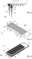
- FIG 4 shows the sample substrate 100 according to the first embodiment, wherein the sample substrate 100 further comprises a plurality of collection cartridges 40, such as Evotips ® , each having a cartridge coupling section 42 with a cartridge opening 43 (see also Figure 10(b) with respect to the second embodiment) and being configured for accommodating the liquid sample from one of the vessels 12.
- the cartridge opening 43 is the only opening of the respective collection cartridge 40.
- Each of the collection cartridges 40 preferably has a shape of a pipette tip, a conus, and/or a column.
- each vessel coupling section 15 is matched to each cartridge coupling section 42 with form-fitting.
- one of the collection cartridges 40 and one of the vessels 12 can be directly coupled with each other by form-fit via the respective vessel coupling section 15 and respective cartridge coupling section 42.
- a direct liquid communication via the vessel opening 13 of the vessel coupling section 15 and the cartridge opening 43 of the cartridge coupling section 42 is provided.
- each vessel coupling section 15 and each cartridge coupling section 42 are adapted for a direct mutual coupling.
- the sample substrate 100 is illustrated in a simplified manner in Figure 4 , comprising only two collection cartridges 40, one being coupled to the vessel 12 and the other one being arranged adjacent to the single plate 10 to illustrate the detachable coupling of a collection cartridge 40 and a vessel 12 provided by the sample substrate 100 according to the present invention.
- each of the vessel coupling sections 15 is formed by the protruding rim at the vessel opening 13 of the vessel coupling section 15, specifically an outer wall section of the sidewall forming the respective vessel 12.
- the protruding rim preferably has a cone shape. The side walls therefore fulfil a double function in terms of forming the vessels 12 on the main plate section 11 and coupling with the collection cartridges 40.
- each of the cartridge coupling sections 42 is provided by an inner wall section at the cartridge opening 43 of the cartridge coupling section 42, specifically an inner wall section of the sidewall forming the collection cartridge 40.
- the side walls of the collection cartridges 40 therefore also fulfil a double function in terms of forming the collection cartridges 40 and coupling with the vessels 12.
- a collection cartridge 40 can be coupled to a vessel 12 in a simple manner by putting the cartridge coupling section 42 over the vessel coupling section 15. This can be done manually or with a machine, in particular in an automated process.
- each of the cartridge coupling sections 42 may be formed by a protruding rim at the cartridge opening 43 of the cartridge coupling section 42, such as an outer wall section of the sidewall forming the collection cartridge 40.
- each of the vessel coupling sections 15 may be provided by an inner wall section at the vessel opening 13 of the vessel coupling section 15, such as an inner wall section of the sidewall forming the vessel 12.
- the sample substrate 100 may be employed for preparing samples for an LC-MS analysis and/or executing an LC-MS sample analysis (e.g., a proteomics mass spectrometry analysis), wherein the sample substrate 100 in particular enables single or low amount cell (e.g., protein) samples preparation for single cell proteomic analyses, wherein sample sizes are generally already low (usually ⁇ ng). All steps of a sample preparation protocol before the subsequent sample analysis can be performed in the sample substrate 100.
- an LC-MS sample analysis e.g., a proteomics mass spectrometry analysis
- samples to be analyzed are collected in the vessels 12.
- the reaction substrate device 100 namely the single plate 10
- the single plate 10 may be placed on a, e.g., table, wherein the vessels 12 are arranged on a top side of the single plate 10 and/or the vessel openings 13 are oriented upwards. That way, the samples can be supplied to the vessels 12 via the vessel openings 13.
- the samples may comprise biological material, such as biological cells, cell groups and/or cell components.
- biological material such as biological cells, cell groups and/or cell components.
- the biological material comprises one single cell, multiple cells or at least one piece of biological material originating from tissue slices (such as fresh frozen tissue or paraffin embedded tissue slices).
- the samples are subjected to decomposition reaction in the vessels 12, wherein the decomposition reaction preferably comprises cell lysis and/or protein digestion.
- the decomposition reaction preferably comprises cell lysis and/or protein digestion.
- reagents are supplied to the vessels 12 that will allow cell lysis and protein digestion of the samples into peptide fragments.
- the liquid samples and the reagents may be supplied using a droplet handling and processing machine, such as an automated pipetting robot, with, e.g., a piezoelectric droplet dispenser.
- the liquid samples and the reagents are supplied by hand pipetting.
- the first two steps may be performed at different temperatures, e.g., from 5 to 100°C.
- each of the collection cartridges 40 are coupled with one of the vessels 12, while the single plate 10 is still in the first position.
- the cartridge openings 43 of the collection cartridges 40 are oriented downwards when the respective cartridge coupling sections 42 are coupled by form-fit to the vessel coupling sections 15. Accordingly, the collection cartridges 40 are arranged at the top side of the single plate 10.
- the decomposed samples are transferred, e.g., pooled, from each of the vessels 12 to the coupled collection cartridges 40.
- the whole sample substrate 100 is turned upside down.
- the sample substrate 100 is moved in the second position, wherein the vessels 12 and the collection cartridges 40 are arranged at a bottom side of the single plate 10. That way, the decomposed samples can flow from each of the vessels 12 to the coupled collection cartridges 40 by the effect of gravity.
- sample transfer e.g., pooling
- a centrifugation e. g. in a laboratory centrifuge
- the collection cartridges 40 filled with the decomposed samples are decoupled from reaction substrate device, namely the single plate 10, and coupled with a LC-MS apparatus.
- the LC-MS apparatus has an input section for sample input.
- cartridge coupling sections are matched to the shape of the sample input section of the LC-MS apparatus, the collection cartridges 40 can be directly (and without an additional pipetting step) coupled with the LC-MS apparatus.
- the LC-MS/MS apparatus is a tandem mass spectrometer, including a liquid chromatography unit and a mass spectrometer.
- the LC-MS apparatus may be an Evosep ® Liquid Chromatography system for mass spectroscopy analysis.
- a LC-MS sample analysis is conducted with the LC-MS apparatus.
- peptide fragments situated in the decomposed samples are subjected to an ionisation, and a first spectrometer stage (survey scan) separates the ions by their mass-to -charge ratio (m/z). Ions of particular m/z ratios are selected. These ions are split into smaller fragment ions, and these fragment ions are introduced into the second spectrometer stage (identification scan) for separation by their m/z-ratio and detection.
- the mass spectrometer can rely on time of flight (TOF) technology. Chromatographic separation may occur in the collection cartridges 40 during the LC-MS sample analysis.
- TOF time of flight
- the reaction substrate device of the sample substrate 200 comprises a stack of two plates, namely a carrier plate 20 and a funnel plate 30.
- Figure 5 shows such a carrier plate 20, which includes a plurality of, preferably rectangular, arrays 22, each having at least two accommodating spaces 23 for accommodating liquid samples.
- each of the plurality of array 22 is an array of nine accommodating spaces 23 each being configured for accommodating a liquid sample.
- each array 22 has a carrier plate coupling section 25 with a vessel section opening 24.
- the arrays 22 are spaced apart from each other or adjacent to each other.
- the, in particular square or rectangular, vessel section opening 24 is the only opening of the respective array 22.
- an arrangement of twelve arrays 22 is provided, comprising two rows of six arrays 22.
- the carrier plate 20 further comprises a main carrier plate section 21 which preferably has a plane shape.
- the main carrier plate section 21 provides a substrate defining the outer lateral size of the reaction substrate device. Properties, such as measures, of the main carrier plate section 21 may be the same or at least similar to properties of the main plate section 11 according to the first embodiment of the invention.
- the arrays 22 are arranged on the main carrier plate section 21.
- all arrays 22 are arranged on one side of the main carrier plate section 21, wherein an opposite side of the main carrier plate section 21 may be used for placing the reaction substrate device, e.g., on a table when collecting samples to be analyzed in the arrays 22.
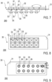
- FIGs 6 , 7, 8 and 9 show the funnel plate 30 according to the second embodiment.
- the funnel plate 30 is shown from different perspectives, namely a perspective view ( Figure 6 ), a side view ( Figure 7 ), a top view ( Figure 8 ) and the bottom view ( Figure 9 ).
- the funnel plate 30 includes a plurality of funnel shaped open passages 32, wherein each funnel shaped open passage 32 comprises a first end having a funnel coupling section 36 with a funnel coupling opening 37, and a second end providing one of the vessel coupling sections 35.
- Each of the vessel coupling sections 35 provides a vessel opening 33.
- the vessel coupling sections 15, 35 of the first and second embodiment, and consequentially also the vessel openings 13, 33 of the first and second embodiments are equal.
- an array of funnel shaped open passages 32 are provided, arranged into rows of six funnel shaped open passage 32, corresponding to the arrangement of the carrier plate vessels 22 of the carrier plate 20 shown in Figure 5 .
- each vessel opening 33 has a square cross-section of 8.2 mm ⁇ 8.2 mm and a distance between centres of funnel shaped open passages 32 is 9 mm.
- each funnel shaped open passage 32 has a total depth of about 7 to 8 mm and a narrowing inner shape with an opening angle of the inner shape towards the vessel opening 33 of 82°.
- the cross-section of each funnel shaped open passage 32 may be constant at the vessel opening 33 up to a depth of about 3 mm, forming the funnel coupling section 36.
- the overall arrangement of the funnel shaped open passages 32 with an outer lateral size of about 55 mm ⁇ 15 mm and a uniform thickness (excluding the vessel coupling sections 35) of about 7 to 8 mm.
- the vessel coupling sections 35 have identical or at least similar properties, in particular measures, like the vessels 12 (and therefore the vessel coupling sections 15) of the first embodiment.
- the vessel coupling sections 35 may have a constant inner shape with a cross-section of 2.5 mm.
- each of the funnel shaped open passages 32 is adapted for fluidically connecting a funnel coupling opening 37 of a funnel coupling section 36 with a vessel opening 33 of the respective vessel coupling section 35.
- the funnel plate 30 further comprises a main funnel plate section 31 which preferably has a plane shape.
- the funnel shaped open passages 32 are arranged within the main funnel plate section 31 and/or pass through the main funnel plate section 31, preferably vertically.
- the first ends of the funnel shaped open passages 32 are arranged on one side of the main funnel plate section 31 and the second ends of the funnel shaped open passages 32, i.e., the vessel coupling sections 35, are arranged on an opposite side of the main funnel plate section 31.
- properties, such as measures, of the main funnel plate section 31 are the same or at least similar to properties of the main carrier plate section 21.
- the main funnel plate section 31 has the same outer lateral size as the carrier plate section 21 of about 75 mm ⁇ 25 mm with a thickness of about 1 mm.
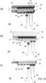
- Figure 10 shows different views of the sample substrate 200 according to the second embodiment, which further comprises the plurality of collection cartridges 40.
- the collection cartridges 40 are preferably identical for both of the first and second embodiments.
- the sample substrate 200 is illustrated in a simplified manner in Figure 10 , comprising only three collection cartridges 40, two being individually coupled to one of vessels, respectively, and the third one being arranged adjacent to the reaction substrate device 200 to illustrate the detachable coupling of a collection cartridge 40 and a vessel provided by the sample substrate 200 according to the present invention.
- each carrier plate coupling section 25 and each funnel coupling section 36 are matched to each other with form-fitting so that they are adapted for coupling the carrier plate 20 and the funnel plate 30.
- the vessels are formed, each composed of one of the arrays 22 of accommodating spaces and one of the funnel shaped open passages 32 coupled to each other, wherein a direct liquid communication between the respective array 22 and funnel shaped open passage 32 is provided via the vessel section opening 24 and the funnel coupling opening 37 thereof.
- a direct communication between the respective carrier plate vessel 22, such as an area of accommodating spaces 23, and a collection cartridge 40 is provided via the funnel shaped open passage 32.
- the sample substrate 200 may be employed for preparing samples for an LC-MS analysis and/or executing an LC-MS sample analysis, similarly to the sample substrate 100, as previously described.
- the sample substrate 200 also enables single or low amount cell (e.g., protein) samples preparation for single cell proteomic analyses, wherein sample sizes are generally already low (usually ⁇ ng). All steps of a sample preparation protocol before the subsequent sample analysis can be performed in the sample substrate 200.
- samples to be analyzed are collected in the vessels, specifically in the accommodating spaces 23 of the arrays 22, and the samples are subjected to decomposition reaction in the accommodating spaces 23.
- the carrier plate 20 is provided in a first position without the plurality of collection cartridges 40.
- the carrier plate 20 may be placed on a, e.g., table, wherein the arrays 22 are arranged on a top side of the carrier plate 20 and/or the vessel section openings 24 are oriented upwards. That way, the samples and, e.g., reagents, can be supplied to the arrays 22 via the vessel section openings 24.
- the first two steps may be performed with or without the funnel plate 30 being coupled to the carrier plate 20.
- the funnel plate 30 may be coupled to the carrier plate 20 after the first two steps have been performed.
- each of the collection cartridges 40 are coupled with one of the vessels, while the carrier plate 20 is still in the first position.
- the funnel plate 30 is coupled to the carrier plate 20 which is still in the first position. Accordingly, the funnel plate 30 and therefore also vessel coupling sections 35 are arranged at the top side of the reaction substrate device.
- the cartridge openings 43 of the collection cartridges 40 are oriented downwards when the respective cartridge coupling sections 42 are coupled by form-fit to the vessel coupling sections 35.
- the funnel plate 30 and the carrier plate 20 are still uncoupled, wherein the collection cartridges 40 are first coupled by form-fit to the vessel coupling sections 35, and then the whole arrangement of the funnel plate 30 and the collection cartridges 40 are placed on top of the carrier plate 20 so that the funnel plate 30 can be coupled to the carrier plate 20.
- the decomposed samples are transferred from each of the vessels to the coupled collection cartridges 40.
- the whole sample substrate 200 is turned upside down, moving the sample substrate 200 in the second position.
- the decomposed samples can flow from each of the vessels to the coupled collection cartridges 40 by the effect of gravity and preferably additionally by centrifugation.
- Possible fifth and sixth steps may correspond to the ones as previously described with respect to the first embodiment.
Landscapes
- Health & Medical Sciences (AREA)
- Chemical & Material Sciences (AREA)
- Clinical Laboratory Science (AREA)
- Chemical Kinetics & Catalysis (AREA)
- Analytical Chemistry (AREA)
- General Health & Medical Sciences (AREA)
- Hematology (AREA)
- Sampling And Sample Adjustment (AREA)
- Other Investigation Or Analysis Of Materials By Electrical Means (AREA)
Priority Applications (3)
| Application Number | Priority Date | Filing Date | Title |
|---|---|---|---|
| EP22211050.4A EP4378583A1 (fr) | 2022-12-02 | 2022-12-02 | Substrat d'échantillon, appareil d'analyse d'échantillon liquide et procédé de réparation d'échantillons liquides, en particulier pour une analyse lc-ms |
| CN202380082734.6A CN120225284A (zh) | 2022-12-02 | 2023-12-01 | 特别用于lc-ms分析的样本基板、液体样本分析装置以及液体样本的制备方法 |
| PCT/EP2023/083997 WO2024115768A1 (fr) | 2022-12-02 | 2023-12-01 | Substrat d'échantillon, appareil d'analyse d'échantillon liquide, et procédé de préparation d'échantillons liquides, en particulier pour une analyse lc-ms |
Applications Claiming Priority (1)
| Application Number | Priority Date | Filing Date | Title |
|---|---|---|---|
| EP22211050.4A EP4378583A1 (fr) | 2022-12-02 | 2022-12-02 | Substrat d'échantillon, appareil d'analyse d'échantillon liquide et procédé de réparation d'échantillons liquides, en particulier pour une analyse lc-ms |
Publications (1)
| Publication Number | Publication Date |
|---|---|
| EP4378583A1 true EP4378583A1 (fr) | 2024-06-05 |
Family
ID=84387699
Family Applications (1)
| Application Number | Title | Priority Date | Filing Date |
|---|---|---|---|
| EP22211050.4A Pending EP4378583A1 (fr) | 2022-12-02 | 2022-12-02 | Substrat d'échantillon, appareil d'analyse d'échantillon liquide et procédé de réparation d'échantillons liquides, en particulier pour une analyse lc-ms |
Country Status (3)
| Country | Link |
|---|---|
| EP (1) | EP4378583A1 (fr) |
| CN (1) | CN120225284A (fr) |
| WO (1) | WO2024115768A1 (fr) |
Citations (5)
| Publication number | Priority date | Publication date | Assignee | Title |
|---|---|---|---|---|
| EP3261762A1 (fr) * | 2015-02-27 | 2018-01-03 | Mastaplex Limited | Réceptacle à échantillons, contenant à échantillons, et procédé d'utilisation |
| US20180326421A1 (en) * | 2015-11-09 | 2018-11-15 | Fernando Martínez Menéndez | Insect tipping assembly and method |
| WO2020225420A1 (fr) * | 2019-05-08 | 2020-11-12 | Scienion Ag | Plaque pour essais ayant des nano-réceptacles et ensemble de récupération d'échantillon |
| WO2021071855A1 (fr) * | 2019-10-07 | 2021-04-15 | Drugarray, Inc. | Dispositif de transfert de matériau et procédé d'utilisation associé |
| EP3964290A1 (fr) | 2020-09-04 | 2022-03-09 | Scienion GmbH | Appareil et procédé de préparation d'échantillons liquides pour analyse d'échantillons |
-
2022
- 2022-12-02 EP EP22211050.4A patent/EP4378583A1/fr active Pending
-
2023
- 2023-12-01 CN CN202380082734.6A patent/CN120225284A/zh active Pending
- 2023-12-01 WO PCT/EP2023/083997 patent/WO2024115768A1/fr not_active Ceased
Patent Citations (5)
| Publication number | Priority date | Publication date | Assignee | Title |
|---|---|---|---|---|
| EP3261762A1 (fr) * | 2015-02-27 | 2018-01-03 | Mastaplex Limited | Réceptacle à échantillons, contenant à échantillons, et procédé d'utilisation |
| US20180326421A1 (en) * | 2015-11-09 | 2018-11-15 | Fernando Martínez Menéndez | Insect tipping assembly and method |
| WO2020225420A1 (fr) * | 2019-05-08 | 2020-11-12 | Scienion Ag | Plaque pour essais ayant des nano-réceptacles et ensemble de récupération d'échantillon |
| WO2021071855A1 (fr) * | 2019-10-07 | 2021-04-15 | Drugarray, Inc. | Dispositif de transfert de matériau et procédé d'utilisation associé |
| EP3964290A1 (fr) | 2020-09-04 | 2022-03-09 | Scienion GmbH | Appareil et procédé de préparation d'échantillons liquides pour analyse d'échantillons |
Non-Patent Citations (3)
| Title |
|---|
| H. SPECHT ET AL., SINGLE-CELL MASS-SPECTROMETRY QUANTIFIES THE EMERGENCE OF MACROPHAGE HETEROGENEITY, Retrieved from the Internet <URL:http://dx.doi.org/10.1101/665307> |
| Y. ZHU ET AL.: "Nanodroplet processing platform for deep and quantitative proteome profiling of 10-100 mammalian cells", NATURE COMMUNICATIONS, vol. 9, 2018, pages 882, XP055611613, DOI: 10.1038/s41467-018-03367-w |
| Z. Y. LI: "Nanoliter-Scale Oil-Air-Droplet Chip-Based Single Cell Proteomic Analysis", ANAL. CHEM., vol. 90, 2018, pages 5430 - 5438, XP002801448 |
Also Published As
| Publication number | Publication date |
|---|---|
| CN120225284A (zh) | 2025-06-27 |
| WO2024115768A1 (fr) | 2024-06-06 |
Similar Documents
| Publication | Publication Date | Title |
|---|---|---|
| JP6514173B2 (ja) | マルチウェル・プレート及び蓋体 | |
| EP2333560B1 (fr) | Procédé de séparation et de détection d'un analyte et appareil dans ce but | |
| EP2629098B1 (fr) | Horloge de flux de travail entre les modules | |
| CA2849917C (fr) | Bandelette reactive unitisee | |
| JP5872765B2 (ja) | 空間的分離による増幅システム | |
| EP2338596B1 (fr) | Plateau pour embouts de pipettes | |
| US8877141B2 (en) | System for preparing arrays of biomolecules | |
| WO1999057561A3 (fr) | Analyseur automatise pour diagnostics et procede correspondant | |
| KR101661098B1 (ko) | 일체화된 반응 및 검출 수단을 구비하는 멀티웰 큐베트 | |
| EP2333558B1 (fr) | Système d'adhérence de verrouillage de forme | |
| JP5819617B2 (ja) | 分析器のハードウェア構成 | |
| EP4378583A1 (fr) | Substrat d'échantillon, appareil d'analyse d'échantillon liquide et procédé de réparation d'échantillons liquides, en particulier pour une analyse lc-ms | |
| EP3964290B1 (fr) | Appareil et procédé de préparation d'échantillons liquides pour analyse d'échantillons | |
| US20240226927A1 (en) | Taylor cone emitter device respository, taylor cone emitter device respository system, and method for analyzing a population of samples | |
| WO2015072718A1 (fr) | Cuvette multi-puits munie de moyens de réaction et détection intégrés | |
| Reed et al. | Automated medium and high-throughput GlycoWorks RapiFluor-ms preparations on the Andrew+ pipetting robot | |
| EP3669983B1 (fr) | Couvercle d'un support d'une membrane pour le transfert de biomolécules et support de membrane pour le transfert de biomolécules pour effectuer une technique de buvardage en taches | |
| Reed et al. | GlycoWorks RapiFluor-MS Automation Using the Andrew+ Pipetting Robot | |
| Marusina | Lab Automation Solutions |
Legal Events
| Date | Code | Title | Description |
|---|---|---|---|
| PUAI | Public reference made under article 153(3) epc to a published international application that has entered the european phase |
Free format text: ORIGINAL CODE: 0009012 |
|
| STAA | Information on the status of an ep patent application or granted ep patent |
Free format text: STATUS: THE APPLICATION HAS BEEN PUBLISHED |
|
| AK | Designated contracting states |
Kind code of ref document: A1 Designated state(s): AL AT BE BG CH CY CZ DE DK EE ES FI FR GB GR HR HU IE IS IT LI LT LU LV MC ME MK MT NL NO PL PT RO RS SE SI SK SM TR |
|
| STAA | Information on the status of an ep patent application or granted ep patent |
Free format text: STATUS: REQUEST FOR EXAMINATION WAS MADE |
|
| 17P | Request for examination filed |
Effective date: 20241203 |
|
| RBV | Designated contracting states (corrected) |
Designated state(s): AL AT BE BG CH CY CZ DE DK EE ES FI FR GB GR HR HU IE IS IT LI LT LU LV MC ME MK MT NL NO PL PT RO RS SE SI SK SM TR |
|
| STAA | Information on the status of an ep patent application or granted ep patent |
Free format text: STATUS: EXAMINATION IS IN PROGRESS |
|
| 17Q | First examination report despatched |
Effective date: 20260206 |