EP4378657A1 - Outil de moulage par injection et procédé de fabrication de pièces moulées par injection - Google Patents
Outil de moulage par injection et procédé de fabrication de pièces moulées par injection Download PDFInfo
- Publication number
- EP4378657A1 EP4378657A1 EP23211112.0A EP23211112A EP4378657A1 EP 4378657 A1 EP4378657 A1 EP 4378657A1 EP 23211112 A EP23211112 A EP 23211112A EP 4378657 A1 EP4378657 A1 EP 4378657A1
- Authority
- EP
- European Patent Office
- Prior art keywords
- injection molding
- compensation
- distribution channel
- molding tool
- volume
- Prior art date
- Legal status (The legal status is an assumption and is not a legal conclusion. Google has not performed a legal analysis and makes no representation as to the accuracy of the status listed.)
- Pending
Links
Images



Classifications
-
- B—PERFORMING OPERATIONS; TRANSPORTING
- B29—WORKING OF PLASTICS; WORKING OF SUBSTANCES IN A PLASTIC STATE IN GENERAL
- B29C—SHAPING OR JOINING OF PLASTICS; SHAPING OF MATERIAL IN A PLASTIC STATE, NOT OTHERWISE PROVIDED FOR; AFTER-TREATMENT OF THE SHAPED PRODUCTS, e.g. REPAIRING
- B29C45/00—Injection moulding, i.e. forcing the required volume of moulding material through a nozzle into a closed mould; Apparatus therefor
- B29C45/03—Injection moulding apparatus
-
- B—PERFORMING OPERATIONS; TRANSPORTING
- B29—WORKING OF PLASTICS; WORKING OF SUBSTANCES IN A PLASTIC STATE IN GENERAL
- B29C—SHAPING OR JOINING OF PLASTICS; SHAPING OF MATERIAL IN A PLASTIC STATE, NOT OTHERWISE PROVIDED FOR; AFTER-TREATMENT OF THE SHAPED PRODUCTS, e.g. REPAIRING
- B29C45/00—Injection moulding, i.e. forcing the required volume of moulding material through a nozzle into a closed mould; Apparatus therefor
- B29C45/17—Component parts, details or accessories; Auxiliary operations
- B29C45/26—Moulds
- B29C45/27—Sprue channels ; Runner channels or runner nozzles
- B29C45/2701—Details not specific to hot or cold runner channels
- B29C45/2703—Means for controlling the runner flow, e.g. runner switches, adjustable runners or gates
-
- B—PERFORMING OPERATIONS; TRANSPORTING
- B29—WORKING OF PLASTICS; WORKING OF SUBSTANCES IN A PLASTIC STATE IN GENERAL
- B29C—SHAPING OR JOINING OF PLASTICS; SHAPING OF MATERIAL IN A PLASTIC STATE, NOT OTHERWISE PROVIDED FOR; AFTER-TREATMENT OF THE SHAPED PRODUCTS, e.g. REPAIRING
- B29C45/00—Injection moulding, i.e. forcing the required volume of moulding material through a nozzle into a closed mould; Apparatus therefor
- B29C45/17—Component parts, details or accessories; Auxiliary operations
- B29C45/26—Moulds
- B29C45/27—Sprue channels ; Runner channels or runner nozzles
- B29C45/2725—Manifolds
-
- B—PERFORMING OPERATIONS; TRANSPORTING
- B29—WORKING OF PLASTICS; WORKING OF SUBSTANCES IN A PLASTIC STATE IN GENERAL
- B29C—SHAPING OR JOINING OF PLASTICS; SHAPING OF MATERIAL IN A PLASTIC STATE, NOT OTHERWISE PROVIDED FOR; AFTER-TREATMENT OF THE SHAPED PRODUCTS, e.g. REPAIRING
- B29C45/00—Injection moulding, i.e. forcing the required volume of moulding material through a nozzle into a closed mould; Apparatus therefor
- B29C45/17—Component parts, details or accessories; Auxiliary operations
- B29C45/18—Feeding the material into the injection moulding apparatus, i.e. feeding the non-plastified material into the injection unit
-
- B—PERFORMING OPERATIONS; TRANSPORTING
- B29—WORKING OF PLASTICS; WORKING OF SUBSTANCES IN A PLASTIC STATE IN GENERAL
- B29C—SHAPING OR JOINING OF PLASTICS; SHAPING OF MATERIAL IN A PLASTIC STATE, NOT OTHERWISE PROVIDED FOR; AFTER-TREATMENT OF THE SHAPED PRODUCTS, e.g. REPAIRING
- B29C45/00—Injection moulding, i.e. forcing the required volume of moulding material through a nozzle into a closed mould; Apparatus therefor
- B29C45/17—Component parts, details or accessories; Auxiliary operations
- B29C45/26—Moulds
- B29C45/2669—Moulds with means for removing excess material, e.g. with overflow cavities
-
- B—PERFORMING OPERATIONS; TRANSPORTING
- B29—WORKING OF PLASTICS; WORKING OF SUBSTANCES IN A PLASTIC STATE IN GENERAL
- B29C—SHAPING OR JOINING OF PLASTICS; SHAPING OF MATERIAL IN A PLASTIC STATE, NOT OTHERWISE PROVIDED FOR; AFTER-TREATMENT OF THE SHAPED PRODUCTS, e.g. REPAIRING
- B29C45/00—Injection moulding, i.e. forcing the required volume of moulding material through a nozzle into a closed mould; Apparatus therefor
- B29C45/17—Component parts, details or accessories; Auxiliary operations
- B29C45/26—Moulds
- B29C45/2673—Moulds with exchangeable mould parts, e.g. cassette moulds
-
- B—PERFORMING OPERATIONS; TRANSPORTING
- B29—WORKING OF PLASTICS; WORKING OF SUBSTANCES IN A PLASTIC STATE IN GENERAL
- B29C—SHAPING OR JOINING OF PLASTICS; SHAPING OF MATERIAL IN A PLASTIC STATE, NOT OTHERWISE PROVIDED FOR; AFTER-TREATMENT OF THE SHAPED PRODUCTS, e.g. REPAIRING
- B29C45/00—Injection moulding, i.e. forcing the required volume of moulding material through a nozzle into a closed mould; Apparatus therefor
- B29C45/17—Component parts, details or accessories; Auxiliary operations
- B29C45/26—Moulds
- B29C2045/2683—Plurality of independent mould cavities in a single mould
- B29C2045/2687—Plurality of independent mould cavities in a single mould controlling the filling thereof
-
- B—PERFORMING OPERATIONS; TRANSPORTING
- B29—WORKING OF PLASTICS; WORKING OF SUBSTANCES IN A PLASTIC STATE IN GENERAL
- B29C—SHAPING OR JOINING OF PLASTICS; SHAPING OF MATERIAL IN A PLASTIC STATE, NOT OTHERWISE PROVIDED FOR; AFTER-TREATMENT OF THE SHAPED PRODUCTS, e.g. REPAIRING
- B29C45/00—Injection moulding, i.e. forcing the required volume of moulding material through a nozzle into a closed mould; Apparatus therefor
- B29C45/17—Component parts, details or accessories; Auxiliary operations
- B29C45/26—Moulds
- B29C45/27—Sprue channels ; Runner channels or runner nozzles
- B29C45/2725—Manifolds
- B29C2045/2733—Inserts, plugs, bushings
-
- B—PERFORMING OPERATIONS; TRANSPORTING
- B29—WORKING OF PLASTICS; WORKING OF SUBSTANCES IN A PLASTIC STATE IN GENERAL
- B29C—SHAPING OR JOINING OF PLASTICS; SHAPING OF MATERIAL IN A PLASTIC STATE, NOT OTHERWISE PROVIDED FOR; AFTER-TREATMENT OF THE SHAPED PRODUCTS, e.g. REPAIRING
- B29C45/00—Injection moulding, i.e. forcing the required volume of moulding material through a nozzle into a closed mould; Apparatus therefor
- B29C45/17—Component parts, details or accessories; Auxiliary operations
- B29C45/26—Moulds
- B29C45/2602—Mould construction elements
Definitions
- the invention relates to an injection molding tool for producing injection molded parts by injecting injection molding material into a cavity with a contour corresponding to the injection molded part to be produced, wherein the injection molding tool has at least one distribution channel for injection molding material which is communicatively connected to the cavity.
- the invention further relates to a method for producing injection-molded parts using such an injection molding tool.
- injection molding machines consist of an injection unit designed to prepare raw material and inject the injection molding material under pressure into an injection molding tool, and a clamping unit that holds the injection molding tool and is designed to open and close it.
- the injection unit usually has a screw shaft that is rotatably guided in a cylinder and has a granulate inlet in the rear area and a machine nozzle at the front, free end. The injection molding material melted in the screw is injected under pressure into the injection molding tool through the machine nozzle.
- the clamping unit has a nozzle-side clamping plate arranged vertically on a machine frame, which supports a nozzle-side tool half.
- the clamping unit also has an opposite clamping plate that is usually hydraulically movable in the direction of the fixed clamping plate and supports an ejector-side tool half of the injection molding tool.
- the molding tool on the ejector side then has an ejector mechanism that includes at least one plunger for pushing the injection molded part out of the cavity.
- the ejector mechanism can also have other parts, for example to create undercut contours.
- the nozzle-side mold half can, for example, have a connection to a heating channel distributor bar with the associated heating channel nozzle.
- EN 10 2011 056 694 B4 discloses an injection molding tool in which mold insert halves of at least one mold insert are installed in slide-in frames and the slide-in frames can be connected to one another to form a slide-in module that can be removed from the frame tool.
- a nozzle-side slide-in frame has at least one nozzle opening for receiving at least one associated injection molding nozzle of the injection molding material distribution unit, which is arranged on the first nozzle-side tool half. This means that the nozzle-side and ejector-side tool halves, together with the mold inserts installed therein, can be removed from the clamping plates of the injection molding machine as an individualized tool block when changing over.
- EP 2 464 501 B1 discloses an injection mold with inlet channels for the inflow of injection molding material. Compensation chambers are provided in the inlet channel, which ensure an even distribution of the injection molding material over a rubber sole of a shoe. Possible volume differences of the rubber profile are automatically compensated and/or the amount of injected material is automatically dosed.
- EP 0 666 791 B2 describes a method for injection molding molded parts made of thermoplastic material, the walls of which enclose a cavity, in which the plastic melt is injected in a predetermined amount into the cavity of a mold and during this and/or afterwards is subjected to a fluidic pressure medium, in particular gas, so that the plastic melt is distributed along the walls of the cavity, forming a cavity and adheres to it.
- a fluidic pressure medium in particular gas
- hollow needles for feeding the pressure media are installed in a stationary manner in the molding tool or their free ends constantly protrude into the mold cavity or cavity or can be temporarily pushed into the mold cavity or cavity.
- the hollow needles are inserted at various points in the cavity. Excess material can be drained from the cavity into a channel via a thin spot and later separated from the molded part as a lost pin.
- the distribution channel has a compensating volume area which has a volume determined by the type and number of cavities connected to the distribution channel for receiving injection molding material during the injection molding process.
- the distribution channel which can be connected to an injection nozzle can have several sections with an associated cavity. The sections can be present in different mold inserts and, when installed, form a common distribution channel which is supplied with injection molding material via the common injection nozzle.
- the compensation volume or, if necessary, two or more compensation volumes can be adapted to the respective combination of the type and number of cavities in such a way that differences in the shot weights and the area are compensated.
- a compensation volume (second cavity) can be arranged for at least one of the mold inserts on the distribution channel leading to the cavity of the mold insert.
- This at least one compensation volume is then dimensioned such that the sum of the volume of the cavity and the associated compensation volume for an injection molded part is the same for each mold insert that is connected to the same distribution channel.
- the mold inserts can be designed integrally in an injection molding tool. However, it is advantageous to have an injection molding tool that can accommodate different mold inserts for different or identical injection molded parts.
- the shot weight for each mold insert i.e. for each injection molded part to be produced, is balanced for mold inserts supplied via a common distribution channel.
- the compensation volume area can have a receiving opening. Furthermore, the injection molding tool can have a compensation insert that fits into the The compensating insert can have a recess communicating with the distribution channel to provide a compensating volume. This means that different compensating inserts with different volumes can be optionally inserted into the receiving opening.
- Such an injection molding tool with at least one receiving opening communicating with the distribution channel has the advantage that, by selectively equipping it with a selected compensation insert, the compensation volume required in each case can be adapted to the shot weight of the other cavities (e.g. mold inserts) connected to the same distribution channel in order to provide approximately the same shot weight for each mold insert.
- the other cavities e.g. mold inserts
- the compensating inserts can have a front side with a recess that provides the compensating volume. A groove leading radially outwards can merge into the recess. The distribution channel can then be connected to the recess via the groove when the compensating insert is inserted into the receiving opening of the injection molding tool.
- the compensation volume is thus connected as a branch from the assigned distribution channel via the groove to the distribution channel.
- the compensating inserts can be cylindrical, for example. It is conceivable that additional asymmetrical contours are present, which ensure a predetermined position of the compensating insert in relation to the associated distribution channel. For this purpose, flattenings, depressions or projections (noses) can be present on the compensating insert.
- the injection molding tool may comprise a set of compensating inserts having recesses of different diameters on their front side.
- This provides an injection molding tool set that, on the one hand, contains, for example, various mold inserts that can be inserted into a slide-in frame, each with at least one cavity for producing an injection-molded part and at least one distribution channel leading into the cavity and receiving openings on the distribution channel as well as a set of different compensation inserts for different compensation volumes.
- the compensation inserts with the required compensation volumes can then be selected and inserted into the compensation openings of the mold inserts in such a way that for each mold insert the volume of cavity and compensation volume connected to the common distribution channel is as equal as possible for the assembly.
- the injection molding tool can have a set of compensation inserts that have at least two different outer diameters.
- the injection molding tool has receiving openings determined by the cavities with a diameter that allows a compensation volume adapted to the cavities to be selected by receiving a diameter corresponding to the receiving opening and the compensation volume.
- Two or more cavities may be connected to a distribution channel, the distribution channel being communicatively connected to at least one compensation volume.
- the position of one of the compensation volumes in relation to one of the cavities and the volume provided by the compensation volume may be determined by the combination of the cavities.
- the compensation volume area for a cavity can, for example, be connected as a branch to the distribution channel in the area of the transition from the distribution channel to the associated cavity. This ensures that the compensation volume is arranged in spatial proximity to the associated cavity. This can, for example, ensure continuous filling of the cavity and the compensation volume.
- a compensation volume can be connected to the distribution channel adjacent to a transition from the distribution channel to a cavity. It is therefore conceivable that there are also cavities that do not have a compensation volume. This is usually the cavity with the largest volume, which determines the shot weight for all other cavities connected to the distribution channel or the common injection molding nozzle.
- the injection molding tool can have an injection molding material distribution unit with a nozzle-side installation frame and an ejector-side installation frame.
- the nozzle-side installation frame and/or the ejector-side installation frame can be designed to accommodate mold inserts, each of which has at least one cavity.
- the distribution channels can be incorporated with the compensation volume areas in the mold inserts or in the nozzle-side installation frame and/or the ejector-side installation frame.
- receiving openings are connected to the distribution channels in the mold inserts, into which appropriately selected compensation inserts with corresponding compensation volumes are then inserted to balance the shot weight. This means that when different mold inserts are combined, the volumes connected to the distribution channel for receiving injection molding material can be balanced in such a way that each mold insert connected to the same injection molding nozzle has approximately the same receiving volume.
- compensation can also be provided by compensation volumes in distribution channels of the installation frame, which then lead to a mold insert. This depends on the structural design of the injection molding tool and the installation frame.
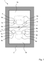
- Figure 1 shows a perspective view of an injection molding tool 1, which has an installation frame 2 for receiving a group of mold inserts 3a, 3b.
- the number of mold inserts 3a, 3b in a group is not limited to the two mold inserts 3a, 3b shown. Rather, any number of at least two mold inserts 3a, 3b can form a group.
- the injection molding tool 1 has a distribution channel 4, which is introduced with several sections in the illustrated embodiment in the separate mold inserts 3a, 3b.
- the sections of the distribution channel 4 are connected to a common injection point 5 for an injection molding material injection nozzle.
- the sections forming a common distribution channel 4 each open into at least one cavity 6a, 6b.
- the cavities 6a, 6b each have a contour and shape in a three-dimensional direction, which determines the shape of the injection-molded part to be produced with a cavity 6a, 6b.
- An injection-molded part is produced by injecting injection-mold material via the common injection-mold material injection nozzle and the sections of the common distribution channel 4 branching off to form the group of cavities 6a, 6b into the cavities 6a, 6b of the group connected to the branches of the distribution channel 4.
- the injection volume for the respective branches from the injection nozzle of the common injection point 5 in the various branches of the common distribution channel 4 shown is different, then uniform filling of the cavities 6a, 6b is no longer guaranteed. This applies in particular to the case where different injection molded parts with different volumes are supplied simultaneously via a common distribution channel 4. It can be seen that the upper cavity 6a has a larger area and thus a larger volume than the lower cavity 6b.
- the same shot weight i.e. the same receiving volume for injection molding material, is set for each branch of the common distribution channel 4 starting from the common injection point 5 by means of compensation volumes 7 which are connected in a communicating manner to the distribution channel 4.
- the compensation volumes 7b for this lower mold insert 3b are noticeably larger than the compensation volumes 7a for the upper mold insert 3a.
- the size of the compensation volumes for a common cavity 6a, 6b can also be different in order to balance out different filling behavior at several junctions into a common cavity 6a, 6b using the compensation volumes 7a, 7b. This is intended to achieve approximately the same filling behavior for all junctions of a cavity 6a, 6b.
- the compensation volumes 7a, 7b can, like the cavities 6a, 6b, be introduced directly into the respective mold 3a, 3b as a compensation cavity. This is a useful simple variant if the composition of the group of cavities 6a, 6b or optionally a group of different molds 3a, 3b for the different cavities 6a, 6b is known and remains unchanged.
- the molds 3a, 3b in the embodiment shown have receiving openings 9a, 9b, which are intended to receive compensation inserts 8a, 8b.
- the receiving openings 9a, 9b can have the same shape, for example the same diameter, so that a type of compensating inserts 8a, 8b with the uniform shape and the uniform diameter can then be inserted into the mold inserts 3a, 3b.
- the receiving openings 9a, 9b are cylindrical. They differ from each other by different diameters.
- two types of receiving openings 9a, 9b and correspondingly two different types of compensation inserts 8a, 8b can be present in a set, which differ from each other by two different diameters.
- three, four or more different types of compensation inserts can also be provided as required.
- a compensating cavity in the form of a hollow space is then introduced into the front side of the compensating inserts 8a, 8b, the volume of which determines the compensating volume 7a, 7b.
- This compensation volume 7a, 7b is then connected to the adjacent section of the distribution channel 4 by appropriate alignment via a groove 10.
- the compensation inserts 8a, 8b can also have an opening closed on the reverse side, via which the compensation volumes 7a, 7b communicate with the adjacent section of the distribution channel 4.
- FIG 2 shows a perspective view of injection molded parts 11a, 11b, which are produced with the injection molding tool 1 from Figure 1 by injecting plastic material as injection molding material. It can be seen that starting from the common injection point 5, webs 12 lead to the injection molded parts 11a, 11b. The webs 12 correspond to the shape and course of the distribution channels 4. Adjacent to the junction with the respective injection molded part 11a, 11b, ie the associated cavity 6a, 6b, the compensating material sections 13a, 13b corresponding to the shape and size of the compensating volumes 7a, 7b are present.
- the volume of the smaller injection molded part 11a, together with the volume of the webs 12 leading to the common injection point 5 and the compensating material 13b, corresponds to the volume of the larger injection molded part 11b. together with the webs and compensating materials 13a leading from the common injection point 5 to this injection-molded part 11b.
- the volume leading to the two injection molded parts 11a, 11b of the two-part group i.e. the shot weight
- the so-called shot weight for the right-hand part of the group as seen from the injection point 5 is approximately equal to the shot weight of the left-hand part of the group.
- FIG 3 shows the representation of the injection molded parts 11a, 11b from Figure 2 now together with the respective compensating inserts 8a, 8b. It can be seen that these are cylindrical and have two different diameters.
- the diameter and depth of the recess determine the desired compensating volume 7a, 7b, which leads to a balanced shot weight for the areas of the group of cavities 6a, 6b and associated injection molded parts 11a, 11b connected to a common injection point 5.
- the groove 10 For a communicating connection with the adjacent distribution channel 4, the groove 10 must be aligned with the adjacent distribution channel 4 or the web 12 produced thereby. This is achieved by means of a suitable alignment contour in the injection molding tool 1 or the respective molding tool 3a, 3b and a corresponding contour on the compensation insert 8a, 8b.
- a suitable alignment contour in the injection molding tool 1 or the respective molding tool 3a, 3b and a corresponding contour on the compensation insert 8a, 8b At the end opposite the front compensation volume 7a, 7b, there is a radially protruding collar 14 which has a flattening 15 as a coding and alignment contour.
- the compensation insert 8a, 8b can therefore only be inserted into a correspondingly coded contoured receiving opening 9a, 9b in such an alignment that ensures the transition of the groove 10 into the adjacent distribution channel 4.
- This alignment contour 15 can, for example, be arranged opposite the groove 10 in the plan view.
- the compensating inserts 8a, 8b have an asymmetrical contour overall, such as a rectangular contour, which allows an insertion into the receiving opening 9a, 9b only in one or two ways, by which an alignment of the groove 10 with the distribution channel 4 is ensured.
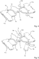
- Figure 4 shows another group of injection molded parts 11a, 11c. It is clear that the injection molded part 11a, which was previously the largest in the first embodiment, now has a smaller volume than the other injection molded part 11c. This is the reason why compensating volumes 7a with the compensating material 13a were also provided on the first injection molded part 11a. This would not be necessary if restricted to the first type of group described above, provided that the largest cavity 6a of a group determines the shot weight.
- the injection molded part 11c forms the largest component to be produced with the injection molding tool 1 and thus determines the largest shot weight.
- no receiving opening 9a, 9b for the use of a compensating insert 8a, 8b is then required.
- a compensation opening 9a, 9b adjacent to the distribution channel 4 can also be provided in the mold 3a, 3b for such a cavity 6c.
- This compensation opening 9a, 9b can then be fitted with a compensation insert 8a, 8b which has a closed front side and thus a compensation volume of zero. In the event that a group is put together in which one cavity 6a, 6b is larger, the required compensation volume can still be set.
- small noses 16 projecting downwards can be seen on the webs 12. These are also present on the other sections of the webs 12. They do not represent a compensating volume 7a, 7b in the sense of the present invention. Their volume is much too small to lead to an effective balancing of the shot weight. Such noses are instead present as a result of deliberate recesses for fixing the position during cooling and ejection or are created by guide openings for the rams of an ejection tool on the ejection side of the mold.
- Figure 5 shows the example from Figure 4 in perspective view with the compensating inserts 8a and the compensating masses 13a accommodated in the front end.
- Figure 6 shows a set of compensating inserts 8a, 8b.
- the set consists of two different types of cylindrical compensating inserts 8a, 8b with different diameters.
- These compensating inserts 8a, 8b each have a compensating cavity 17 with different diameters on their front side.
- the depths of the compensating cavities 17 can also differ from one another for the compensating inserts 8a, 8b of a set. This provides different compensating volumes 7a, 7b.
- the mold inserts 3a, 3b can be coordinated with one another when assembling a group of mold inserts 3a, 3b and thus a group of cavities 6a, 6b in such a way that the shot weights of the cavities 6a, 6b formed at a common injection point 5 with the common distribution channel 4 each accommodate the same injection molding volume.
- the compensating cavities 17 on the front sides of the compensating inserts 8a, 8b are delimited by a circumferential edge 18 which is perforated by a groove 10 leading radially outwards.
- the depth of the groove 10 can be deeper than the depth of the compensation cavity 17.
- the design of the groove 10 can influence the flow behavior.
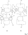
- Figure 7 a) and b) shows a top view of the Figures 1 to 3 shown first group and in Figures 4 and 5 shown second group of injection molded parts 11a, 11b, 11c.
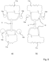
- Figure 8 a) and b) shows another top view of the injection molded parts 11a, 11b, 11c produced after injection of the injection molding material with the webs 12 and leveling masses 13a, 13a ⁇ , 13b formed thereon after removal from the injection molding tool 1.
Landscapes
- Engineering & Computer Science (AREA)
- Manufacturing & Machinery (AREA)
- Mechanical Engineering (AREA)
- Moulds For Moulding Plastics Or The Like (AREA)
- Injection Moulding Of Plastics Or The Like (AREA)
Applications Claiming Priority (1)
| Application Number | Priority Date | Filing Date | Title |
|---|---|---|---|
| DE102022131019.1A DE102022131019A1 (de) | 2022-11-23 | 2022-11-23 | Spritzgusswerkzeug und Verfahren zur Herstellung von Spritzguss-Formteilen |
Publications (1)
| Publication Number | Publication Date |
|---|---|
| EP4378657A1 true EP4378657A1 (fr) | 2024-06-05 |
Family
ID=88920874
Family Applications (1)
| Application Number | Title | Priority Date | Filing Date |
|---|---|---|---|
| EP23211112.0A Pending EP4378657A1 (fr) | 2022-11-23 | 2023-11-21 | Outil de moulage par injection et procédé de fabrication de pièces moulées par injection |
Country Status (4)
| Country | Link |
|---|---|
| US (1) | US12617133B2 (fr) |
| EP (1) | EP4378657A1 (fr) |
| CN (1) | CN118061463A (fr) |
| DE (1) | DE102022131019A1 (fr) |
Families Citing this family (1)
| Publication number | Priority date | Publication date | Assignee | Title |
|---|---|---|---|---|
| CN122033249B (zh) * | 2026-04-14 | 2026-06-23 | 西安工业大学 | 一种带变形预补偿功能的粉末注射成形模具 |
Citations (9)
| Publication number | Priority date | Publication date | Assignee | Title |
|---|---|---|---|---|
| JPS5941239A (ja) * | 1982-08-31 | 1984-03-07 | Matsushita Electric Works Ltd | 射出成形用金型 |
| JPH08323817A (ja) * | 1995-06-01 | 1996-12-10 | Polyplastics Co | 合成樹脂製品の射出成形用金型及びその金型を使用した射出成形方法 |
| EP0666791B2 (fr) | 1992-10-08 | 2000-09-13 | Battenfeld GmbH | Procede de moulage par injection de pieces en matiere thermoplastique et outil permettant la mise en oeuvre dudit procede |
| JP3092348B2 (ja) * | 1992-09-09 | 2000-09-25 | 株式会社デンソー | 射出成形用金型 |
| JP2001341166A (ja) * | 2000-05-31 | 2001-12-11 | Matsushita Electric Ind Co Ltd | 射出成形金型装置 |
| JP2002192561A (ja) * | 2000-12-22 | 2002-07-10 | Canon Inc | 成形用金型 |
| EP2464501B1 (fr) | 2009-08-11 | 2013-07-17 | Eurosuole S.P.A. | Moule d injection à chambre de compensation permettant le moulage du tpu et d autres matériaux thermoplastiques sur une semelle de caoutchouc |
| DE102011056694B4 (de) | 2011-12-20 | 2014-03-06 | Wago Verwaltungsgesellschaft Mbh | Spritzgusswerkzeug und Verfahren zur Umrüstung eines solchen Spritzgusswerkzeugs in einer Spritzgussmaschine |
| KR20200015125A (ko) * | 2018-08-02 | 2020-02-12 | (주)연우 | 다수 캐비티 금형의 유동밸런스 미세조정 장치 |
Family Cites Families (4)
| Publication number | Priority date | Publication date | Assignee | Title |
|---|---|---|---|---|
| DE2252201A1 (de) | 1972-10-25 | 1974-05-22 | 5090 Leverkusen | Vorrichtung zum herstellen von formteilen aus schnell miteinander reagierenden chemischen komponenten |
| US6450798B1 (en) * | 2000-02-04 | 2002-09-17 | Avaya Technology Corp. | Apparatus for multiple cavity injection molding |
| WO2002000414A1 (fr) * | 2000-06-28 | 2002-01-03 | Beaumont Runner Technologies, Inc. | Procede et appareil permettant d'equilibrer les conditions d'ecoulement de materiaux a ecoulement laminaire |
| US7614872B2 (en) * | 2005-10-04 | 2009-11-10 | Mold-Masters (2007) Limited | Melt redistribution element for an injection molding apparatus |
-
2022
- 2022-11-23 DE DE102022131019.1A patent/DE102022131019A1/de active Pending
-
2023
- 2023-11-21 US US18/516,939 patent/US12617133B2/en active Active
- 2023-11-21 CN CN202311554923.7A patent/CN118061463A/zh active Pending
- 2023-11-21 EP EP23211112.0A patent/EP4378657A1/fr active Pending
Patent Citations (9)
| Publication number | Priority date | Publication date | Assignee | Title |
|---|---|---|---|---|
| JPS5941239A (ja) * | 1982-08-31 | 1984-03-07 | Matsushita Electric Works Ltd | 射出成形用金型 |
| JP3092348B2 (ja) * | 1992-09-09 | 2000-09-25 | 株式会社デンソー | 射出成形用金型 |
| EP0666791B2 (fr) | 1992-10-08 | 2000-09-13 | Battenfeld GmbH | Procede de moulage par injection de pieces en matiere thermoplastique et outil permettant la mise en oeuvre dudit procede |
| JPH08323817A (ja) * | 1995-06-01 | 1996-12-10 | Polyplastics Co | 合成樹脂製品の射出成形用金型及びその金型を使用した射出成形方法 |
| JP2001341166A (ja) * | 2000-05-31 | 2001-12-11 | Matsushita Electric Ind Co Ltd | 射出成形金型装置 |
| JP2002192561A (ja) * | 2000-12-22 | 2002-07-10 | Canon Inc | 成形用金型 |
| EP2464501B1 (fr) | 2009-08-11 | 2013-07-17 | Eurosuole S.P.A. | Moule d injection à chambre de compensation permettant le moulage du tpu et d autres matériaux thermoplastiques sur une semelle de caoutchouc |
| DE102011056694B4 (de) | 2011-12-20 | 2014-03-06 | Wago Verwaltungsgesellschaft Mbh | Spritzgusswerkzeug und Verfahren zur Umrüstung eines solchen Spritzgusswerkzeugs in einer Spritzgussmaschine |
| KR20200015125A (ko) * | 2018-08-02 | 2020-02-12 | (주)연우 | 다수 캐비티 금형의 유동밸런스 미세조정 장치 |
Also Published As
| Publication number | Publication date |
|---|---|
| CN118061463A (zh) | 2024-05-24 |
| US20240165862A1 (en) | 2024-05-23 |
| US12617133B2 (en) | 2026-05-05 |
| DE102022131019A1 (de) | 2024-05-23 |
Similar Documents
| Publication | Publication Date | Title |
|---|---|---|
| DE69319825T2 (de) | Verfahren und Vorrichtung zur Fluidverdichtung eines spritzgegossenen Kunststoffes | |
| EP0895848B1 (fr) | Dispositif de fabrication d'articles moulés par injection d'au moins deux matières plastiques fondues | |
| EP0424624B1 (fr) | Moule d'injection pour des pièces injectées en matière plastifiable, notamment en polymères à cristaux liquides plastifiables | |
| DE2445786B2 (de) | Vorrichtung zur Herstellung eines Spritzgußteiles | |
| EP0049390A2 (fr) | Moule d'injection pour la fabrication de corps moulés de deux sortes de matières plastique | |
| EP0744266B1 (fr) | Procédé et dispositif pour mouler par injection des corps creux soufflés en matière plastique | |
| AT519256B1 (de) | Verfahren und Vorrichtung zur Herstellung von Bauteilen oder Profilen | |
| EP0666791B2 (fr) | Procede de moulage par injection de pieces en matiere thermoplastique et outil permettant la mise en oeuvre dudit procede | |
| DE4022778C2 (fr) | ||
| DE102022131019A1 (de) | Spritzgusswerkzeug und Verfahren zur Herstellung von Spritzguss-Formteilen | |
| DE19948279B4 (de) | Verfahren und Vorrichtung zum Spritzgießen von Kunststoff-Formteilen | |
| EP2134528B1 (fr) | Moule avec cadre, à structure modulaire | |
| DE102021115687A1 (de) | Einspritzeinheit für eine Formgebungsmaschine und Verfahren zum Einspritzen | |
| DE10052068B4 (de) | Werkzeug einer Spritzguß- oder Spritzprägemaschine, Verfahren zur Herstellung einer implantierbaren Linse sowie implantierbare Linse | |
| EP1046486B1 (fr) | Outil de moulage pour fabriquer plusieurs pièces montées par moulage par injection | |
| EP1440782B1 (fr) | Appareil et procédé pour produire des objects plastiques en utilisant des moules à injecter avec des dispositifs de décélération de flux et leur utilisation | |
| DE19703291C1 (de) | Verfahren zum Herstellen eines aus mindestens zwei unterschiedlichen Kunststoffen bestehenden Kunststoffgegenstandes | |
| EP1005408A1 (fr) | Procede et dispositif de moulage par injection de pieces en materiau plastifiable | |
| EP1338398A1 (fr) | Dispositif pour le moulage à plusieurs composants d'objets en matière plastique | |
| DE10331642A1 (de) | Vorrichtung zum Spritzgießen von Formkörpern aus Kunststoff | |
| DE60307685T2 (de) | Verfahren und vorrichtung zum giessen verschiedener formen in einer stranggiessanlage in einem einzigen giessvorgang | |
| DE4235776C2 (de) | Formwerkzeug zum Herstellen von Kunststoffteilen sowie Verfahren zum Herstellen eines solchen Formwerkzeugs | |
| DE102008056670B4 (de) | Verfahren zum Betreiben einer Spritzgießeinrichtung | |
| CH653286A5 (en) | Multi-cavity injection mould | |
| DE102006018132B4 (de) | Verfahren und Vorrichtung zum Herstellen eines Duroplastformteils |
Legal Events
| Date | Code | Title | Description |
|---|---|---|---|
| PUAI | Public reference made under article 153(3) epc to a published international application that has entered the european phase |
Free format text: ORIGINAL CODE: 0009012 |
|
| STAA | Information on the status of an ep patent application or granted ep patent |
Free format text: STATUS: THE APPLICATION HAS BEEN PUBLISHED |
|
| AK | Designated contracting states |
Kind code of ref document: A1 Designated state(s): AL AT BE BG CH CY CZ DE DK EE ES FI FR GB GR HR HU IE IS IT LI LT LU LV MC ME MK MT NL NO PL PT RO RS SE SI SK SM TR |
|
| STAA | Information on the status of an ep patent application or granted ep patent |
Free format text: STATUS: REQUEST FOR EXAMINATION WAS MADE |
|
| 17P | Request for examination filed |
Effective date: 20240613 |
|
| RBV | Designated contracting states (corrected) |
Designated state(s): AL AT BE BG CH CY CZ DE DK EE ES FI FR GB GR HR HU IE IS IT LI LT LU LV MC ME MK MT NL NO PL PT RO RS SE SI SK SM TR |