EP4378659A1 - Dispositif d'installation de moulage par soufflage et installation de moulage par soufflage - Google Patents
Dispositif d'installation de moulage par soufflage et installation de moulage par soufflage Download PDFInfo
- Publication number
- EP4378659A1 EP4378659A1 EP24161356.1A EP24161356A EP4378659A1 EP 4378659 A1 EP4378659 A1 EP 4378659A1 EP 24161356 A EP24161356 A EP 24161356A EP 4378659 A1 EP4378659 A1 EP 4378659A1
- Authority
- EP
- European Patent Office
- Prior art keywords
- transport
- blow molding
- molding system
- containers
- designed
- Prior art date
- Legal status (The legal status is an assumption and is not a legal conclusion. Google has not performed a legal analysis and makes no representation as to the accuracy of the status listed.)
- Pending
Links
Images





Classifications
-
- B—PERFORMING OPERATIONS; TRANSPORTING
- B29—WORKING OF PLASTICS; WORKING OF SUBSTANCES IN A PLASTIC STATE IN GENERAL
- B29C—SHAPING OR JOINING OF PLASTICS; SHAPING OF MATERIAL IN A PLASTIC STATE, NOT OTHERWISE PROVIDED FOR; AFTER-TREATMENT OF THE SHAPED PRODUCTS, e.g. REPAIRING
- B29C49/00—Blow-moulding, i.e. blowing a preform or parison to a desired shape within a mould; Apparatus therefor
- B29C49/42—Component parts, details or accessories; Auxiliary operations
- B29C49/4205—Handling means, e.g. transfer, loading or discharging means
- B29C49/42065—Means specially adapted for transporting preforms
-
- B—PERFORMING OPERATIONS; TRANSPORTING
- B29—WORKING OF PLASTICS; WORKING OF SUBSTANCES IN A PLASTIC STATE IN GENERAL
- B29C—SHAPING OR JOINING OF PLASTICS; SHAPING OF MATERIAL IN A PLASTIC STATE, NOT OTHERWISE PROVIDED FOR; AFTER-TREATMENT OF THE SHAPED PRODUCTS, e.g. REPAIRING
- B29C49/00—Blow-moulding, i.e. blowing a preform or parison to a desired shape within a mould; Apparatus therefor
- B29C49/42—Component parts, details or accessories; Auxiliary operations
- B29C49/4205—Handling means, e.g. transfer, loading or discharging means
- B29C49/42073—Grippers
- B29C49/42085—Grippers holding inside the neck
-
- B—PERFORMING OPERATIONS; TRANSPORTING
- B29—WORKING OF PLASTICS; WORKING OF SUBSTANCES IN A PLASTIC STATE IN GENERAL
- B29C—SHAPING OR JOINING OF PLASTICS; SHAPING OF MATERIAL IN A PLASTIC STATE, NOT OTHERWISE PROVIDED FOR; AFTER-TREATMENT OF THE SHAPED PRODUCTS, e.g. REPAIRING
- B29C49/00—Blow-moulding, i.e. blowing a preform or parison to a desired shape within a mould; Apparatus therefor
- B29C49/42—Component parts, details or accessories; Auxiliary operations
- B29C49/64—Heating or cooling preforms, parisons or blown articles
- B29C49/6409—Thermal conditioning of preforms
- B29C49/6418—Heating of preforms
-
- B—PERFORMING OPERATIONS; TRANSPORTING
- B29—WORKING OF PLASTICS; WORKING OF SUBSTANCES IN A PLASTIC STATE IN GENERAL
- B29C—SHAPING OR JOINING OF PLASTICS; SHAPING OF MATERIAL IN A PLASTIC STATE, NOT OTHERWISE PROVIDED FOR; AFTER-TREATMENT OF THE SHAPED PRODUCTS, e.g. REPAIRING
- B29C2949/00—Indexing scheme relating to blow-moulding
- B29C2949/07—Preforms or parisons characterised by their configuration
- B29C2949/0715—Preforms or parisons characterised by their configuration the preform having one end closed
-
- B—PERFORMING OPERATIONS; TRANSPORTING
- B29—WORKING OF PLASTICS; WORKING OF SUBSTANCES IN A PLASTIC STATE IN GENERAL
- B29C—SHAPING OR JOINING OF PLASTICS; SHAPING OF MATERIAL IN A PLASTIC STATE, NOT OTHERWISE PROVIDED FOR; AFTER-TREATMENT OF THE SHAPED PRODUCTS, e.g. REPAIRING
- B29C49/00—Blow-moulding, i.e. blowing a preform or parison to a desired shape within a mould; Apparatus therefor
- B29C49/28—Blow-moulding apparatus
- B29C49/30—Blow-moulding apparatus having movable moulds or mould parts
- B29C49/36—Blow-moulding apparatus having movable moulds or mould parts rotatable about one axis
-
- B—PERFORMING OPERATIONS; TRANSPORTING
- B29—WORKING OF PLASTICS; WORKING OF SUBSTANCES IN A PLASTIC STATE IN GENERAL
- B29C—SHAPING OR JOINING OF PLASTICS; SHAPING OF MATERIAL IN A PLASTIC STATE, NOT OTHERWISE PROVIDED FOR; AFTER-TREATMENT OF THE SHAPED PRODUCTS, e.g. REPAIRING
- B29C49/00—Blow-moulding, i.e. blowing a preform or parison to a desired shape within a mould; Apparatus therefor
- B29C49/42—Component parts, details or accessories; Auxiliary operations
- B29C49/4205—Handling means, e.g. transfer, loading or discharging means
- B29C49/42093—Transporting apparatus, e.g. slides, wheels or conveyors
- B29C49/42095—Rotating wheels or stars
-
- B—PERFORMING OPERATIONS; TRANSPORTING
- B29—WORKING OF PLASTICS; WORKING OF SUBSTANCES IN A PLASTIC STATE IN GENERAL
- B29C—SHAPING OR JOINING OF PLASTICS; SHAPING OF MATERIAL IN A PLASTIC STATE, NOT OTHERWISE PROVIDED FOR; AFTER-TREATMENT OF THE SHAPED PRODUCTS, e.g. REPAIRING
- B29C49/00—Blow-moulding, i.e. blowing a preform or parison to a desired shape within a mould; Apparatus therefor
- B29C49/42—Component parts, details or accessories; Auxiliary operations
- B29C49/4205—Handling means, e.g. transfer, loading or discharging means
- B29C49/42113—Means for manipulating the objects' position or orientation
- B29C49/42117—Translation e.g. telescopic movement to pick up a preform
-
- B—PERFORMING OPERATIONS; TRANSPORTING
- B29—WORKING OF PLASTICS; WORKING OF SUBSTANCES IN A PLASTIC STATE IN GENERAL
- B29C—SHAPING OR JOINING OF PLASTICS; SHAPING OF MATERIAL IN A PLASTIC STATE, NOT OTHERWISE PROVIDED FOR; AFTER-TREATMENT OF THE SHAPED PRODUCTS, e.g. REPAIRING
- B29C49/00—Blow-moulding, i.e. blowing a preform or parison to a desired shape within a mould; Apparatus therefor
- B29C49/42—Component parts, details or accessories; Auxiliary operations
- B29C49/4236—Drive means
- B29C49/42362—Electric drive means, e.g. servomotors
-
- B—PERFORMING OPERATIONS; TRANSPORTING
- B65—CONVEYING; PACKING; STORING; HANDLING THIN OR FILAMENTARY MATERIAL
- B65G—TRANSPORT OR STORAGE DEVICES, e.g. CONVEYORS FOR LOADING OR TIPPING, SHOP CONVEYOR SYSTEMS OR PNEUMATIC TUBE CONVEYORS
- B65G17/00—Conveyors having an endless traction element, e.g. a chain, transmitting movement to a continuous or substantially-continuous load-carrying surface or to a series of individual load-carriers; Endless-chain conveyors in which the chains form the load-carrying surface
- B65G17/30—Details; Auxiliary devices
- B65G17/48—Controlling attitudes of load-carriers during movement
-
- B—PERFORMING OPERATIONS; TRANSPORTING
- B65—CONVEYING; PACKING; STORING; HANDLING THIN OR FILAMENTARY MATERIAL
- B65G—TRANSPORT OR STORAGE DEVICES, e.g. CONVEYORS FOR LOADING OR TIPPING, SHOP CONVEYOR SYSTEMS OR PNEUMATIC TUBE CONVEYORS
- B65G47/00—Article or material-handling devices associated with conveyors; Methods employing such devices
- B65G47/74—Feeding, transfer, or discharging devices of particular kinds or types
- B65G47/84—Star-shaped wheels or devices having endless travelling belts or chains, the wheels or devices being equipped with article-engaging elements
- B65G47/846—Star-shaped wheels or wheels equipped with article-engaging elements
- B65G47/847—Star-shaped wheels or wheels equipped with article-engaging elements the article-engaging elements being grippers
Definitions
- the present invention relates to a blow molding system arrangement for a blow molding system with at least one container transport device, which has a plurality of circumferentially arranged transport elements for receiving containers, which are arranged to be movable in a transport direction along a transport path and wherein a transfer section adjoins the transport path in the transport direction, wherein a transfer device is designed to remove the containers in the transfer section from the transport elements, wherein the container transport device has a device which is designed to move the transport elements in the transfer section starting from an operating position in a stroke direction arranged perpendicular to the transport direction.
- blow molding system arrangements relate to individual components or to arrangements of components in blow molding systems, whereby in the context of the invention these are in particular blow molding systems for the beverage industry.
- the blow molding systems serve to form beverage containers, in particular bottles, from preforms, which are generally also referred to as preforms.
- preforms are usually made of a plastic, e.g. polyethylene terephthalate (PET), so that they can be plastically deformed in a simple manner during the blow molding process.
- PET polyethylene terephthalate
- the preforms are first heated to a predetermined temperature, which enables plastic deformation.
- a so-called stretching rod is then inserted into the preforms, which increases the length of the preforms.
- the interior of the preforms is then pressurized by blowing in compressed air, whereby the walls are pressed into an adjacent blow mold.
- the containers formed can then be removed from the blow mold.
- both the preforms and the finished beverage containers can be understood as containers, they are preferably preforms which are transported via the container transport device before being introduced into the actual blow molding machine.
- the container transport devices In practice, it has been shown that it is often a problem for the container transport devices if the containers or preforms cannot be removed from the transport elements by the transfer device in the transfer section. This can be the case, for example, if the transfer device is no longer exactly synchronized with the container transport device during operation.
- the individual system components are usually driven by independent electric motors, in particular servo motors, so that the individual system components are no longer forcibly coupled to one another. Minor inaccuracies in the operation of the electric motors can then lead to a corresponding asynchronicity.
- the containers that have not been removed can then block the acceptance of new containers or even collide with components of the blow molding system arrangement during further transport.
- the present invention is based on the object of specifying a blow molding system arrangement which is characterized by improved operating behavior and greater reliability compared to the previously known blow molding system arrangements. At the same time, any downtimes should also be reduced.
- a stripping element is arranged behind the transfer section in the transport direction.
- This stripping element is intended to reliably remove containers that have not been removed from the transport elements by the transfer device in the transfer section, thereby ensuring that a container can be transported along the transport path again by the now exposed transport element.
- the stripping element is therefore a type of safety device that ensures that the containers are removed if the transfer device is not functioning properly. For example, if the transfer device is slightly damaged or faulty, it is possible to allow the blow molding system arrangement to continue operating for a certain period of time. Even if the transfer device fails completely, e.g. due to asynchrony, it can be ensured that the containers do not hit components, e.g. a partition wall of the container transport device, and damage them.
- the transport elements are thus initially moved along the transport route in an operating position and then transferred to the transfer position via the lifting device.
- This has the advantage that the transport elements can initially be guided out of the row of transport elements arranged one behind the other and the transfer device can then easily remove the containers in the transport elements without colliding with other containers or transport elements.
- the transport elements are moved from the operating position downwards into the transfer position. This lifting movement then makes it possible to easily release containers from the stripping element.
- the containers are arranged below the stripping element, with the stripping element being designed in such a way that the container strikes the stripping element during further transport and is thereby released.
- the stripping element is designed to release the containers from the transport elements during a movement counter to the lifting direction.
- the transport elements are transferred to the transfer position in the transfer section in the lifting direction. Behind the transfer section, an opposite lifting movement then takes place, which transfers the transport elements back to the operating position and enables new containers to be picked up.
- This opposite lifting movement then causes the containers to be released from the stripping element, in that sections of the container strike the stripping element and cause them to be released from the transport element.
- preforms or the like which are usually fully formed in a head section.
- This head section accordingly has an external thread for screwing on closure caps. Below the thread there is also a so-called support ring, which represents the largest width of the preform and is therefore particularly suitable for being brought into contact with the stripping element.
- the lifting device is therefore designed to move the transport elements in the transfer section at least along a basic stroke, wherein the basic stroke is at least 8 mm, preferably at least 9 mm, particularly preferably at least 10 mm.
- This basic stroke is sufficient on the one hand to position the support rings of the containers below the stripping element and at the same time to enable a sufficient stroke in the opposite direction, which enables the containers to be released from the transport elements.
- This basic stroke therefore represents a lower limit which must not be undercut during operation of the container transport device.
- the lifting device is assigned an adjusting device for adjusting the stroke.
- the lifting device can be adjusted or different strokes can be selected.
- the adjusting device is preferably designed to adjust the lifting device between at least two stroke positions.
- a first stroke setting preferably causes the transport elements to be transferred from an operating position to the transfer position, while the second stroke position only causes a basic stroke.
- the stroke for transferring to the transfer position is greater than the basic stroke, the ratio preferably being at least 2:1, particularly preferably at least 2.5:1. is. Switching between these two stroke positions can be based on error detection, for example.
- the actuating device If the actuating device is informed, for example, that the container transport device and the transfer device are no longer running synchronously with each other, it can then switch from a first to a second stroke position. In such a case, the transfer device would no longer be able to remove containers from the transport elements. However, it would be ensured that in any case, removal from the transport elements would take place for a certain period of time, whereby this period could then be used to take the blow molding system out of operation.
- the lifting device is designed as a curve control.
- the lifting movement can be brought about solely by the design of the curve control.
- the transport elements preferably have a guide roller arrangement at an upper end, which can roll in the transport direction along an associated guide track arrangement.
- the guide track arrangement has a path which causes the transport elements to move in the lifting direction and, behind the transfer section, a movement against the lifting direction.
- the guide roller arrangement can also be adjusted preferably in the lifting direction by the adjusting device, so that the guide roller arrangement no longer effects the maximum possible lift. This makes it possible to switch between the basic lift and a lift for transferring to the transfer position.
- the guide roller arrangement is formed from at least two guide rollers and the guide track arrangement from at least two guide tracks, with a first guide track having a track section that can be adjusted in the stroke direction via the adjusting device.
- Each of the guide rollers is thus guided along an associated guide track, with the guide rollers in the active position preferably being able to roll underneath a guide track.
- either the first or the second guide track is in the active position and thus in the transfer section in the stroke direction.
- the respective guide track then forms the path effective for the respective stroke.
- the first guide track also has an adjustable track section in the transfer section, so that this either protrudes in relation to the second guide track in a first switching state or is set back in relation to the second guide track in a second switching state.
- the first switching state preferably causes the stroke for transferring the transport elements into the transfer position and the second switching state a basic stroke.
- the transport device is preferably designed as a heating device.
- the material striking the transfer device is significantly softer.
- a preferred embodiment further provides that the stripping element is initially curved in sections.
- This is preferably a design in which the stripping element slopes downwards in an end section. This makes it possible to give the containers transported in the transport elements a certain downward impulse after they have been released in the stripping element, which ensures that the container falls downwards as quickly as possible after being released and does not strike elements or components behind it due to the movement in the transport direction.
- the container transport device is designed as a heating device, with heating elements being arranged at least in sections along the transport route.
- a heating device is usually provided in blow molding systems in order to bring the material of the containers or preforms to a temperature that enables plastic deformation.
- the heating elements are arranged at least in sections along the transport route and cause the containers to heat up gradually as they move along.
- the heating elements are usually designed as heat radiation elements and therefore cause the containers to heat up essentially on the basis of the heat radiation that is applied.
- the heating elements are preferably infrared radiation elements.
- the transport elements preferably have shielding elements which, in an operational state, are arranged in a head region of the containers and ensure that the Radiation is kept below the radiation element. This is to prevent unwanted heating of the machine components.
- the head area of the containers or preforms which is usually already designed with an external thread for screwing on a closure cap, does not soften. Instead, the radiation should be kept in the lower area of the preforms, where softening and correspondingly plastic deformation is desired.
- the radiating elements are always arranged above the stripping element.
- the present invention also has clear advantages over previous solutions with regard to these radiating elements. If, for example, the corresponding container cannot be removed from the transport element, this leads in a next step to a collision with a partition wall arranged behind it, which is necessary to separate the cold inlet from the hot outlet of the heating device. A collision with this partition wall, however, inevitably leads to bending of the radiating elements, since the containers - as already explained - are arranged with a head area within these radiating elements.
- Only emergency stop switches have been arranged on the partition wall, which switch off the entire system in the event of a collision with the container. With the invention, further operation is now possible, at least for the time being.
- the containers are also removed from the transport elements in good time before damage can occur to other components, e.g. radiating elements.
- At least one emergency stop switch can be arranged on a partition wall arranged behind the stripping element, which is designed so that a container transported in the transport element hits this emergency stop switch.
- the switch can be designed as a proximity switch, for example. Accordingly, a further safety barrier is provided, which ultimately causes the entire system to be shut down in the event of a stripping element not functioning properly.
- the transfer device has one or more grippers which are designed to grip the containers in the transfer section.
- the grippers can be designed differently.
- a preferred embodiment provides that each gripper is formed from two gripper parts which interact to grip the containers on the outside.
- the lifting device is preferably designed so that the grippers grip the containers in a head area. Accordingly, the transfer stroke in the transfer position of the transport elements means that the grippers can grip and remove the containers in the head area.
- a drive device is assigned to the container transport device for transporting the transport elements in the transport direction and/or to the transfer device.
- both devices each have a separate drive device.
- the drive devices are designed as an electric motor, in particular as a servo motor.
- both drive devices are controlled separately by a control device and drive the container transport device and the transfer device independently of one another.
- the movements of both devices must be synchronized with one another so that the grippers of the transfer device can remove the containers from the container transport device at a suitable location.
- the design according to the invention with a stripping element is of particular importance.
- the invention further relates to a blow molding plant according to claim 14 with a blow molding plant arrangement according to the invention, wherein a blow molding machine is arranged downstream of the container transport device in the production direction and wherein a transfer device for transferring the Container is arranged between the container transport device and the blow molding machine.
- the blow molding machine is the machine which causes plastic deformation of the containers transported in the container transport machine.
- the container transport device is a heating device
- the containers transported in the container transport device are first heated and softened in the form of preforms, with the transfer device then transferring the heated and softened preforms to the blow molding system.
- the preforms are then enclosed in a blow mold and plastically deformed by blowing in pressure.
- the Fig.1 shows a blow molding system according to the invention with a blow molding machine 1, which is designed to produce containers 2 designed as preforms and form them into plastic bottles.
- the containers 2 are made of a plastically deformable material.
- these are preforms made of polyethylene terephthalate (PET).
- the containers 2 are fed to the blow molding system via a feed 3, usually designed as a chute, and are transferred to a container transport arrangement 5 designed as a heating device by means of a separating wheel 4. Within the container transport device 5 designed as a heating device, the containers 2 are continuously moved along a transport path 9, with heating elements 6 continuously heating the containers 2 to a temperature that enables plastic deformation by introducing high pressure within the blow molding machine 1.
- the heating elements 6 are designed according to the Fig.1 designed as heat radiation elements and heat the containers 2 by heat radiation in the infrared range.
- a transfer device 7 is set up to remove the heated containers 2 in a transfer section 8 of the transport path 9 of the container transport device 5 and to transfer them to the blow molding machine 1.
- the transfer device 7 usually has several grippers for this purpose, which are arranged on a base body of the transfer device 7 and wherein the transfer of the containers 2 to the blow molding machine 1 is made possible by rotation of the transfer device 7.
- both the container transport device 5 and the transfer device 7 have a separate drive device designed as a servo motor, whereby the movement of the two components must be precisely coordinated with one another. If there is a certain asynchronicity, this can lead to the grippers of the transfer device 7 no longer gripping the containers 2 precisely, so that As a result, the containers 2 remain in the transport elements 10 of the container transport device 5 and, for example, strike a partition wall 11 which is arranged behind the transfer section 8 and which separates the cold inlet of the container transport device 5 from the hot outlet. This can lead to damage to various components. Another problem arises if, for example, a gripper of the transfer device 7 is damaged and, for this reason, removal of the containers 2 from the respective transport element 10 is not possible.
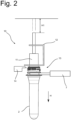
- the Fig.2 shows in this context a more detailed representation of a transport element 10 in the area of the transfer section 8.
- the container 2 is held within the transport element 10 by a holding element 11.
- a so-called shielding element 12 is located above the container 2 and thereby prevents the heat radiation from reaching the head area 13 of the container 2.
- This head area 13 is already designed with an external thread, which allows the inclusion of a closure cap.
- this shielding element 12 is intended to prevent heat from penetrating to the outside.
- the container transport device 5 has a lifting device which is designed to move the transport elements 10 in the transfer section 8 in a lifting manner.
- the transport element 10 is in a transfer position which enables the transfer device 7 to grip and remove the container 2 in the head region 13.
- the transport element 10 is moved from an operating position to the transfer position with a stroke H1 in the stroke direction H.
- a counter-movement takes place against the stroke direction H, whereby the transport element 10 is transferred back to the operating position.
- Fig.2 a stripping element 14, which is designed to release the containers 2 from the transport elements 10 in the course of a movement against the stroke direction H, should this not be done by the transfer device 7.
- the exact function is explained in particular by the Fig.3 clearly.
- This figure shows how the transport element 10 is transferred back into the operating position, with the container 2 still arranged in the transport element 10.
- the container 2 strikes the stripping element 14 with its support ring 15, whereby the container 2 is released. It is therefore necessary to ensure in every case that the container 2 or the support ring 15 is always moved below the stripping element 14, so that at least a minimal stroke must be provided, which is referred to as the basic stroke H2 in the context of the invention.
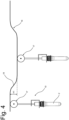
- This basic stroke H2 is in the Fig.5 shown.
- each transport element 10 has a guide roller arrangement 17 at an upper end, which rolls below a guide track arrangement 16.
- the track path is designed such that the guide roller arrangement 17 is guided downwards in the stroke direction H, with the transport elements 10 executing the stroke H1.
- the track path has a reversed path path.
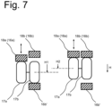
- the guide track arrangement 16 is formed from a first and a second guide track 16a, 16b and the guide roller arrangement 17 from a first and a second guide roller 17a, 17b, wherein the first guide roller 16a can roll along the first guide track 17a and the second guide roller 16b can roll along the second guide track 17b.
- the two guide rollers 16a, 16b are also connected to one another in their axis of rotation.
- the guide roller arrangement 17 In a first switching state shown on the left, the first guide roller 17a below the first guide track 16a in the adjustable track section 18, while the second guide roller 17b rolls above the second guide track 16b'.
- the guide roller arrangement 17 is moved against the stroke direction H into a second switching state shown on the right, or the guide roller arrangement 17 only performs the basic stroke H2.
- the second guide roller 16b By moving the guide roller arrangement, the second guide roller 16b now lies below the second guide track 16b.
- Such a design makes it possible to change from the stroke H1 to a basic stroke H2, which is smaller than the stroke H1, which enables the container 2 to be transferred to the transfer position.
- the basic stroke H2 is designed in such a way that it is ensured that the container 2 with its support ring 15 is arranged below the stripping element 14.
- the Fig.8 shows a side view according to the Fig.3 , whereby it is clear that the stripping element 14 is curved in one end section.
- the containers 2 moved in the transport direction T are given a downward impulse after being released from the transport element 10, which ensures that the containers 2 are conveyed downwards as quickly as possible and do not strike the partition wall 6.
Landscapes
- Engineering & Computer Science (AREA)
- Manufacturing & Machinery (AREA)
- Mechanical Engineering (AREA)
- Physics & Mathematics (AREA)
- Thermal Sciences (AREA)
- Blow-Moulding Or Thermoforming Of Plastics Or The Like (AREA)
Applications Claiming Priority (2)
| Application Number | Priority Date | Filing Date | Title |
|---|---|---|---|
| DE102022118647.4A DE102022118647A1 (de) | 2022-07-26 | 2022-07-26 | Blasformanlagenanordnung sowie Blasformanlage |
| EP23183212.2A EP4311653A3 (fr) | 2022-07-26 | 2023-07-04 | Dispositif d'installation de moulage par soufflage et installation de moulage par soufflage |
Related Parent Applications (2)
| Application Number | Title | Priority Date | Filing Date |
|---|---|---|---|
| EP23183212.2A Division EP4311653A3 (fr) | 2022-07-26 | 2023-07-04 | Dispositif d'installation de moulage par soufflage et installation de moulage par soufflage |
| EP23183212.2A Division-Into EP4311653A3 (fr) | 2022-07-26 | 2023-07-04 | Dispositif d'installation de moulage par soufflage et installation de moulage par soufflage |
Publications (1)
| Publication Number | Publication Date |
|---|---|
| EP4378659A1 true EP4378659A1 (fr) | 2024-06-05 |
Family
ID=87074784
Family Applications (2)
| Application Number | Title | Priority Date | Filing Date |
|---|---|---|---|
| EP24161356.1A Pending EP4378659A1 (fr) | 2022-07-26 | 2023-07-04 | Dispositif d'installation de moulage par soufflage et installation de moulage par soufflage |
| EP23183212.2A Withdrawn EP4311653A3 (fr) | 2022-07-26 | 2023-07-04 | Dispositif d'installation de moulage par soufflage et installation de moulage par soufflage |
Family Applications After (1)
| Application Number | Title | Priority Date | Filing Date |
|---|---|---|---|
| EP23183212.2A Withdrawn EP4311653A3 (fr) | 2022-07-26 | 2023-07-04 | Dispositif d'installation de moulage par soufflage et installation de moulage par soufflage |
Country Status (2)
| Country | Link |
|---|---|
| EP (2) | EP4378659A1 (fr) |
| DE (1) | DE102022118647A1 (fr) |
Citations (7)
| Publication number | Priority date | Publication date | Assignee | Title |
|---|---|---|---|---|
| US3860104A (en) * | 1973-04-19 | 1975-01-14 | Indian Head Inc | Bottle conveyor system including adjustable height continuous belt conveyor and positive lock spray shielded rotatable bottle carrier |
| DE2941576A1 (de) * | 1979-10-13 | 1981-04-23 | Vetter Joachim | Sortiervorrichtung fuer gefaesse,,insbesondere hohlglasgefaesse |
| JPH0957824A (ja) * | 1995-08-25 | 1997-03-04 | Mitsubishi Heavy Ind Ltd | パリソン搬送装置 |
| US20100159060A1 (en) * | 2005-08-29 | 2010-06-24 | Sidel Participations | Device for loading or unloading containers comprising a neck on a transporting element |
| US20150231816A1 (en) * | 2012-08-20 | 2015-08-20 | Nissei Asb Machine Co., Ltd. | Blow molding machine |
| US10363697B2 (en) * | 2015-04-29 | 2019-07-30 | Sidel Participations | Method for controlling a conveyor for hollow bodies through a heating station and associated conveyor |
| US20220032528A1 (en) * | 2018-11-02 | 2022-02-03 | Sidel Participations | Method of managing preforms immobilized in a heating station |
Family Cites Families (1)
| Publication number | Priority date | Publication date | Assignee | Title |
|---|---|---|---|---|
| DE102012101653A1 (de) | 2012-02-29 | 2013-08-29 | Krones Ag | Preformtransport mit individueller Auswurfmöglichkeit |
-
2022
- 2022-07-26 DE DE102022118647.4A patent/DE102022118647A1/de active Pending
-
2023
- 2023-07-04 EP EP24161356.1A patent/EP4378659A1/fr active Pending
- 2023-07-04 EP EP23183212.2A patent/EP4311653A3/fr not_active Withdrawn
Patent Citations (7)
| Publication number | Priority date | Publication date | Assignee | Title |
|---|---|---|---|---|
| US3860104A (en) * | 1973-04-19 | 1975-01-14 | Indian Head Inc | Bottle conveyor system including adjustable height continuous belt conveyor and positive lock spray shielded rotatable bottle carrier |
| DE2941576A1 (de) * | 1979-10-13 | 1981-04-23 | Vetter Joachim | Sortiervorrichtung fuer gefaesse,,insbesondere hohlglasgefaesse |
| JPH0957824A (ja) * | 1995-08-25 | 1997-03-04 | Mitsubishi Heavy Ind Ltd | パリソン搬送装置 |
| US20100159060A1 (en) * | 2005-08-29 | 2010-06-24 | Sidel Participations | Device for loading or unloading containers comprising a neck on a transporting element |
| US20150231816A1 (en) * | 2012-08-20 | 2015-08-20 | Nissei Asb Machine Co., Ltd. | Blow molding machine |
| US10363697B2 (en) * | 2015-04-29 | 2019-07-30 | Sidel Participations | Method for controlling a conveyor for hollow bodies through a heating station and associated conveyor |
| US20220032528A1 (en) * | 2018-11-02 | 2022-02-03 | Sidel Participations | Method of managing preforms immobilized in a heating station |
Also Published As
| Publication number | Publication date |
|---|---|
| EP4311653A2 (fr) | 2024-01-31 |
| DE102022118647A1 (de) | 2024-02-01 |
| EP4311653A3 (fr) | 2024-06-19 |
Similar Documents
| Publication | Publication Date | Title |
|---|---|---|
| EP3216584B1 (fr) | Procédé de fonctionnement d'une installation de manipulation de récipient et installation de manipulation de récipient | |
| EP3448597B1 (fr) | Procédé de transport pour la manutention de pièces | |
| EP3789323A1 (fr) | Préhenseur de récipient et dispositif de transport de récipients | |
| EP4159408A1 (fr) | Dispositif de chauffage d'ébauches en plastique dotées d'une plaque de blindage | |
| EP4378659A1 (fr) | Dispositif d'installation de moulage par soufflage et installation de moulage par soufflage | |
| WO2017186672A1 (fr) | Dispositif de transport pour déplacer des pièces dans un dispositif d'usinage | |
| WO2023078706A1 (fr) | Dispositif d'alimentation et procédé d'alimentation permettant d'alimenter et de transférer des récipients dans une machine de nettoyage de récipients | |
| EP3103616A1 (fr) | Dispositif et procédé destinés à la fabrication de récipients en matière plastique ovales | |
| EP1581362A1 (fr) | Procede et dispositif pour acheminer un element en forme de vis a une unite de traitement | |
| EP4067049A1 (fr) | Dispositif de formage de préformes en matière plastique en des récipients en matière plastique pourvu d'entraînements découplés | |
| EP4028183B1 (fr) | Dispositif et procédé de laminage par étirage | |
| EP4375047B1 (fr) | Machine de moulage par soufflage avec détection d'état de verrouillage | |
| EP2743056B1 (fr) | Acheminement de préforme optimisé | |
| WO2025002661A1 (fr) | Procédé de fonctionnement d'une machine de moulage par soufflage | |
| WO2025017118A1 (fr) | Système de traitement de récipients pour le traitement de récipients | |
| EP1345715A1 (fr) | Presse a forger dotee d'un dispositif de reglage situe cote matrice | |
| EP4656560A1 (fr) | Dispositif de transport de récipients, installation de soufflage et procédé de fonctionnement | |
| EP4711311A1 (fr) | Dispositif d'éjection, système de transport et installation de fabrication et/ou de traitement de récipients | |
| DE102022118912A1 (de) | Behälterbehandlungsanordnung sowie Verfahren zum Betrieb | |
| DE102023122552A1 (de) | Behältertransportvorrichtung zum Transport von Behältern | |
| EP3103617B1 (fr) | Dispositif et procede destines a la fabrication de recipients en matiere plastique ovales | |
| WO2025157599A1 (fr) | Appareil de traitement, de remplissage et/ou d'étiquetage de corps creux, contrôleur associé et procédé l'utilisant | |
| EP1437316A1 (fr) | Traitement de matériaux en bande continue | |
| DE102023113713A1 (de) | Vorrichtung und Verfahren zum Transportieren von Behältern und/oder Vorformlingen | |
| EP3103618B1 (fr) | Dispositif et procédé destinés a la fabrication de récipients en matière plastique ovales |
Legal Events
| Date | Code | Title | Description |
|---|---|---|---|
| PUAI | Public reference made under article 153(3) epc to a published international application that has entered the european phase |
Free format text: ORIGINAL CODE: 0009012 |
|
| STAA | Information on the status of an ep patent application or granted ep patent |
Free format text: STATUS: THE APPLICATION HAS BEEN PUBLISHED |
|
| AC | Divisional application: reference to earlier application |
Ref document number: 4311653 Country of ref document: EP Kind code of ref document: P |
|
| AK | Designated contracting states |
Kind code of ref document: A1 Designated state(s): AL AT BE BG CH CY CZ DE DK EE ES FI FR GB GR HR HU IE IS IT LI LT LU LV MC ME MK MT NL NO PL PT RO RS SE SI SK SM TR |
|
| STAA | Information on the status of an ep patent application or granted ep patent |
Free format text: STATUS: REQUEST FOR EXAMINATION WAS MADE |
|
| 17P | Request for examination filed |
Effective date: 20241205 |
|
| P01 | Opt-out of the competence of the unified patent court (upc) registered |
Free format text: CASE NUMBER: UPC_APP_0014561_4378659/2025 Effective date: 20251125 |