EP4378718A1 - Élément de châssis et procédé de fabrication d'un élément de châssis - Google Patents
Élément de châssis et procédé de fabrication d'un élément de châssis Download PDFInfo
- Publication number
- EP4378718A1 EP4378718A1 EP22210563.7A EP22210563A EP4378718A1 EP 4378718 A1 EP4378718 A1 EP 4378718A1 EP 22210563 A EP22210563 A EP 22210563A EP 4378718 A1 EP4378718 A1 EP 4378718A1
- Authority
- EP
- European Patent Office
- Prior art keywords
- base body
- chassis component
- guide elements
- opening
- contact
- Prior art date
- Legal status (The legal status is an assumption and is not a legal conclusion. Google has not performed a legal analysis and makes no representation as to the accuracy of the status listed.)
- Granted
Links
Images


Classifications
-
- B—PERFORMING OPERATIONS; TRANSPORTING
- B60—VEHICLES IN GENERAL
- B60G—VEHICLE SUSPENSION ARRANGEMENTS
- B60G7/00—Pivoted suspension arms; Accessories thereof
- B60G7/001—Suspension arms, e.g. constructional features
-
- B—PERFORMING OPERATIONS; TRANSPORTING
- B60—VEHICLES IN GENERAL
- B60G—VEHICLE SUSPENSION ARRANGEMENTS
- B60G11/00—Resilient suspensions characterised by arrangement, location or kind of springs
-
- B—PERFORMING OPERATIONS; TRANSPORTING
- B21—MECHANICAL METAL-WORKING WITHOUT ESSENTIALLY REMOVING MATERIAL; PUNCHING METAL
- B21D—WORKING OR PROCESSING OF SHEET METAL OR METAL TUBES, RODS OR PROFILES WITHOUT ESSENTIALLY REMOVING MATERIAL; PUNCHING METAL
- B21D17/00—Forming single grooves in sheet metal or tubular or hollow articles
- B21D17/02—Forming single grooves in sheet metal or tubular or hollow articles by pressing
-
- B—PERFORMING OPERATIONS; TRANSPORTING
- B21—MECHANICAL METAL-WORKING WITHOUT ESSENTIALLY REMOVING MATERIAL; PUNCHING METAL
- B21D—WORKING OR PROCESSING OF SHEET METAL OR METAL TUBES, RODS OR PROFILES WITHOUT ESSENTIALLY REMOVING MATERIAL; PUNCHING METAL
- B21D22/00—Shaping without cutting, by stamping, spinning, or deep-drawing
- B21D22/02—Stamping using rigid devices or tools
- B21D22/04—Stamping using rigid devices or tools for dimpling
-
- B—PERFORMING OPERATIONS; TRANSPORTING
- B21—MECHANICAL METAL-WORKING WITHOUT ESSENTIALLY REMOVING MATERIAL; PUNCHING METAL
- B21D—WORKING OR PROCESSING OF SHEET METAL OR METAL TUBES, RODS OR PROFILES WITHOUT ESSENTIALLY REMOVING MATERIAL; PUNCHING METAL
- B21D53/00—Making other particular articles
- B21D53/88—Making other particular articles other parts for vehicles, e.g. cowlings, mudguards
-
- B—PERFORMING OPERATIONS; TRANSPORTING
- B60—VEHICLES IN GENERAL
- B60G—VEHICLE SUSPENSION ARRANGEMENTS
- B60G7/00—Pivoted suspension arms; Accessories thereof
- B60G7/02—Attaching arms to sprung part of vehicle
-
- B—PERFORMING OPERATIONS; TRANSPORTING
- B60—VEHICLES IN GENERAL
- B60G—VEHICLE SUSPENSION ARRANGEMENTS
- B60G2200/00—Indexing codes relating to suspension types
- B60G2200/40—Indexing codes relating to the wheels in the suspensions
- B60G2200/46—Indexing codes relating to the wheels in the suspensions camber angle
-
- B—PERFORMING OPERATIONS; TRANSPORTING
- B60—VEHICLES IN GENERAL
- B60G—VEHICLE SUSPENSION ARRANGEMENTS
- B60G2200/00—Indexing codes relating to suspension types
- B60G2200/40—Indexing codes relating to the wheels in the suspensions
- B60G2200/462—Toe-in/out
- B60G2200/4622—Alignment adjustment
-
- B—PERFORMING OPERATIONS; TRANSPORTING
- B60—VEHICLES IN GENERAL
- B60G—VEHICLE SUSPENSION ARRANGEMENTS
- B60G2204/00—Indexing codes related to suspensions per se or to auxiliary parts
- B60G2204/10—Mounting of suspension elements
-
- B—PERFORMING OPERATIONS; TRANSPORTING
- B60—VEHICLES IN GENERAL
- B60G—VEHICLE SUSPENSION ARRANGEMENTS
- B60G2204/00—Indexing codes related to suspensions per se or to auxiliary parts
- B60G2204/10—Mounting of suspension elements
- B60G2204/14—Mounting of suspension arms
- B60G2204/143—Mounting of suspension arms on the vehicle body or chassis
-
- B—PERFORMING OPERATIONS; TRANSPORTING
- B60—VEHICLES IN GENERAL
- B60G—VEHICLE SUSPENSION ARRANGEMENTS
- B60G2204/00—Indexing codes related to suspensions per se or to auxiliary parts
- B60G2204/40—Auxiliary suspension parts; Adjustment of suspensions
- B60G2204/44—Centering or positioning means
-
- B—PERFORMING OPERATIONS; TRANSPORTING
- B60—VEHICLES IN GENERAL
- B60G—VEHICLE SUSPENSION ARRANGEMENTS
- B60G2204/00—Indexing codes related to suspensions per se or to auxiliary parts
- B60G2204/61—Adjustable during maintenance
-
- B—PERFORMING OPERATIONS; TRANSPORTING
- B60—VEHICLES IN GENERAL
- B60G—VEHICLE SUSPENSION ARRANGEMENTS
- B60G2206/00—Indexing codes related to the manufacturing of suspensions: constructional features, the materials used, procedures or tools
- B60G2206/01—Constructional features of suspension elements, e.g. arms, dampers, springs
- B60G2206/10—Constructional features of arms
- B60G2206/121—Constructional features of arms the arm having an H or X-shape
-
- B—PERFORMING OPERATIONS; TRANSPORTING
- B60—VEHICLES IN GENERAL
- B60G—VEHICLE SUSPENSION ARRANGEMENTS
- B60G2206/00—Indexing codes related to the manufacturing of suspensions: constructional features, the materials used, procedures or tools
- B60G2206/01—Constructional features of suspension elements, e.g. arms, dampers, springs
- B60G2206/10—Constructional features of arms
- B60G2206/16—Constructional features of arms the arm having a U profile and/or made of a plate
-
- B—PERFORMING OPERATIONS; TRANSPORTING
- B60—VEHICLES IN GENERAL
- B60G—VEHICLE SUSPENSION ARRANGEMENTS
- B60G2206/00—Indexing codes related to the manufacturing of suspensions: constructional features, the materials used, procedures or tools
- B60G2206/01—Constructional features of suspension elements, e.g. arms, dampers, springs
- B60G2206/70—Materials used in suspensions
- B60G2206/71—Light weight materials
- B60G2206/7102—Aluminium alloys
-
- B—PERFORMING OPERATIONS; TRANSPORTING
- B60—VEHICLES IN GENERAL
- B60G—VEHICLE SUSPENSION ARRANGEMENTS
- B60G2206/00—Indexing codes related to the manufacturing of suspensions: constructional features, the materials used, procedures or tools
- B60G2206/01—Constructional features of suspension elements, e.g. arms, dampers, springs
- B60G2206/80—Manufacturing procedures
- B60G2206/81—Shaping
- B60G2206/8102—Shaping by stamping
-
- B—PERFORMING OPERATIONS; TRANSPORTING
- B60—VEHICLES IN GENERAL
- B60G—VEHICLE SUSPENSION ARRANGEMENTS
- B60G2206/00—Indexing codes related to the manufacturing of suspensions: constructional features, the materials used, procedures or tools
- B60G2206/01—Constructional features of suspension elements, e.g. arms, dampers, springs
- B60G2206/80—Manufacturing procedures
- B60G2206/81—Shaping
- B60G2206/8105—Shaping by extrusion
-
- B—PERFORMING OPERATIONS; TRANSPORTING
- B60—VEHICLES IN GENERAL
- B60G—VEHICLE SUSPENSION ARRANGEMENTS
- B60G2206/00—Indexing codes related to the manufacturing of suspensions: constructional features, the materials used, procedures or tools
- B60G2206/01—Constructional features of suspension elements, e.g. arms, dampers, springs
- B60G2206/80—Manufacturing procedures
- B60G2206/83—Punching
Definitions
- the present invention relates to a chassis component according to the features in the preamble of claim 1 and to a method for producing a chassis component according to the features in claim 16.
- Chassis components which in particular serve to guide and stabilize the wheel suspension connected to a wheel of the motor vehicle, are mechanically connected to the wheel suspension and the chassis of the motor vehicle.
- One such chassis component is in particular a spring link.
- the mechanical connection can be made via an eccentric mechanism.
- Chassis components with a corresponding eccentric mechanism usually have an opening and two Guide elements for guiding an eccentric element.
- the eccentric element is made of an eccentric disk or eccentric screw, which have a collar that is arranged eccentrically with respect to the axis of rotation of the eccentric element.
- the collar of the eccentric element is in contact with the guide elements.
- the opening in the chassis component is usually designed as an elongated hole, so that the chassis component, in particular the spring link, is moved further outwards or inwards of the vehicle by the guide elements when the eccentric element rotates.
- the US 11 338 635 B2 a multi-leg control arm for a wheel suspension in a vehicle, wherein an eccentric disk of a corresponding eccentric mechanism is designed to rest on guide elements in order to guide the control arm with respect to an axle carrier and/or wheel carrier when the eccentric disk rotates and thus to determine the steering camber and/or track.
- the guide elements are formed in one piece from the material of a control arm and have a rectangular shape with rounded ends. Due to the shape of the guide elements, a high pressure is required for the molding process. Due to the high pressure, clamping joints or other damage can remain on the component as a result of the molding process, which can in particular reduce the service life of the chassis component.
- US 11 260 715 B2 shows a corresponding eccentric mechanism with guide elements.
- the guide elements are designed with cutting technology, which can have a negative effect on the service life of the component and increases the risk of cracks forming within the guide elements.
- the object of the present invention is to provide a chassis component with guide elements which achieves a longer service life and is cost-effective to manufacture.
- the chassis component according to the invention which is preferably a wishbone and in particular a spring link, has a base body, the base body preferably being a link arm of the spring link.
- the base body also has an opening for passing through a fastening means.
- Two guide elements for guiding an eccentric element are arranged on the opposite sides of the opening.
- the guide elements are formed by mechanical processing in one piece and from the same material from the base body of the chassis component. This design makes the manufacture of the guide elements particularly simple and cost-effective, since no separate component is required and the guide elements are easily formed from the material of the chassis component. Due to the one-piece design and material unit, additional fastening of the guide elements is not necessary. This can prevent them from slipping or coming loose in the finished chassis component, as would be possible if a separate component was used. This significantly increases the service life of the component and permanently ensures the adjustment for track and/or camber.
- the guide elements each have a rear side and a contact side facing the opening.
- the contact side is aligned orthogonally to the base body.
- the guide elements come into contact with the eccentric element via the contact sides and thus ensure that the chassis component is displaced when the eccentric element is rotated accordingly. When the eccentric element rotates, a force is transferred to the guide elements via the contact sides.
- an outer transition area with a radius is formed between the respective contact sides and the base body.
- the guide elements are subjected to high loads due to the force transmitted by the eccentric elements. In particular, cracks often form at the transition point between the contact side and the base body due to this load. The service life of the chassis component is thus reduced.
- the transition area according to the invention between the contact sides and the base body initially increases the material thickness in this critical area.
- the formation of the transition area with a radius according to the invention, which connects the contact sides to the base body significantly reduces the risk of cracks forming.
- the service life of the chassis component is thus increased.
- the radius formed also ensures a secure fit between the contact side and the eccentric element.
- the shape of the transition area according to the invention is suitable for the cost-effective production of the chassis component by moving material from the chassis component out of the base body.
- the radius of the outer transition region according to the invention is preferably between 0.2 mm and 2 mm, particularly preferably between 0.5 mm and 1.5 mm. Appropriate dimensioning has proven to be particularly advantageous for the stability of the guide elements.
- the backs of the guide elements taper in the opposite direction to the contact sides and merge into the base body.
- the guide elements Due to the tapering of the backs and the transition into the base body, the guide elements can be designed to be very space-saving.
- the guide elements can take up a total area of less than 20 mm 2 on the base body, preferably between 4 and 18 mm 2 , particularly preferably between 6 and 15 mm 2 . Surprisingly, it has been shown that this shape of the guide elements counteracts material fatigue despite the small area. Due to the shape of the guide elements, the fiber flow of the material is not interrupted, which in particular leads to a low tendency for cracking.
- the Guide elements Due to the material-uniform tapering of the backs with a corresponding transition into the base body, the Guide elements are also extremely robust.
- the force transmitted by the eccentric element can be transferred very well to the base body thanks to the shape of the guide elements.
- the shape of the guide elements is also suitable for the cost-effective production of the chassis component by moving the material of the chassis component out of the base body.
- the contact sides have a plano-convex shape.
- the plano-convex shape of the contact sides aligned orthogonally to the base body forms an optimal contact for the eccentric element and in particular prevents the eccentric element from slipping.
- the side of the contact side facing away from the base body can have a flattened area, at least in sections, that runs parallel to the base body.
- the flattened area can be completely flat, or less curved, so that an overall flatter contact surface is obtained than with a plano-convex design of the contact side.
- the base body preferably has an indentation below the guide elements.
- the indentation has a front side and a top side, with the front side being arranged parallel to the contact side.
- a corresponding indentation is formed in particular by the manufacturing process of the guide elements, since the material of the base body is displaced outwards, for example by a stamp.
- a parallel alignment of the front side with the contact side leads to increased stability between the guide elements and the base body, which has an advantageous effect on the force flow and the service life of the chassis component.
- an inner transition area with a radius is arranged between the front and the top.
- the transition area increases the stability of the guide elements and reduces the risk of cracks at the contact point between the front and the top.
- the base body has a bottom side in the area of the opening.
- a lower transition area with a radius can be formed between the front side and the bottom side.
- the chassis component can be designed in such a way that the inner transition area merges directly into the lower transition area. In this case, no separate front side is formed between the transition areas.
- an orthogonal distance is formed between the parallel front side and the contact side, which corresponds to between 10% and 50% of the material thickness of the base body. This ensures sufficient material thickness between the contact side and the front side, so that sufficient stability of the guide elements is provided.
- the distance according to the invention between the front side and the contact side achieves an optimal shape or size of the guide elements.
- the distance corresponds in particular to between 20% and 40% of the material thickness of the base body and particularly preferably between 25% and 35% of the material thickness of the base body.
- a distance is formed between the outer transition area and the inner transition area, which corresponds to between 30% and 80% of the material thickness of the base body.
- This is the shortest distance between the inner transition area and the outer transition area.
- a distance according to the invention leads to a stable material structure with a low risk of cracking.
- the fiber flow of the material is not interrupted by the distance between the transition areas according to the invention.
- the distance is preferably between 40% and 60% of the material thickness of the base body and particularly preferably between 45% and 55% of the material thickness of the base body. This distance is determined to a large extent by the presence of the radius of the outer transition area according to the invention and the radius of the inner transition area.
- the chassis component is made of a light metal material, in particular an aluminum alloy.
- the weight of the chassis component is reduced, which has a positive effect on the driving characteristics and fuel consumption of the vehicle.
- the chassis component is an extruded profile. This means that chassis components with complex and irregular shapes can also be manufactured.
- the guide elements are particularly preferably cold-formed. This enables short processing times, good surface quality, tight dimensional tolerances, optimal material utilization and permanent hardening of the material.
- the fiber flow of the material is also not interrupted. Cold forming preserves the continuous structure of the material without creating a tendency to crack formation. Due to the displacement or relocation of the material instead of an incision and the associated essentially uninterrupted fiber flow, a cut-related fracture component in the contact side is avoided and the risk of cracks forming and growing during the manufacture of the chassis component, especially during its service life, is reduced.
- the contact sides have a height that is less than or equal to the material thickness of the base body. Since the guide elements are formed in one piece and from the same material from the base body of the chassis component, this ensures that the material thickness of the guide elements is sufficient for the load from the eccentric element.
- the opening in the base body of the chassis component is in particular an elongated hole.
- a corresponding elongated hole makes it possible to move the chassis component relative to the eccentric element.
- the chassis component precursor is preferably a wishbone, in particular a spring link.
- the chassis component has two opposing spring arms, each with a base body, wherein both base bodies are simultaneously provided with corresponding guide elements during the forming process.
- the chassis component precursor is made of an aluminum alloy and is an extruded profile.
- the base body already has an opening for passing through a fastening means, so that the guide elements can be formed on opposite sides of the opening for guiding an eccentric element.
- an opening for passing through a fastening means can be created in the base body at the same time as the guide elements, with the guide elements also being arranged on opposite sides of the opening.
- two forming steps can be carried out in one, which speeds up the manufacturing process.
- the guide elements are preferably formed using a cold forming process. This enables short processing times, good surface quality, tight dimensional tolerances, optimal material utilization and permanent hardening of the material.
- the fiber flow of the material is also not interrupted.
- the base body is placed in the forming tool so that it rests on the lower die.
- the base body is fixed to the lower die by the fixing element.
- the guide elements are formed by linear feed of the punch.
- the punch presses the material of the base body into the corresponding mold recesses. Due to the inventive oblique alignment of the stamp to the base body, only a low pressure is required compared to conventional manufacturing processes. This is preferably between 5 t and 20 t, particularly preferably between 7.5 t and 13 t. The lower pressure can save energy costs.
- both the forming tool and the chassis component precursor are subjected to less stress.
- the material of the base body is not damaged by the forming tool, so that no weak points remain in the material.
- the oblique alignment of the stamp also leads to an advantageous fiber flow within the material, which enables the guide elements to be very robust.
- no cutting of the material is required, which also improves the robustness and strength of the guide elements according to the invention.
- the head of the stamp is preferably designed in such a way that the contact sides of the guide elements have a plano-convex shape as a result of the forming process and the rear sides taper in the opposite direction to the contact sides and merge into the base body.
- the mold recesses of the lower die are also designed accordingly.
- the head of the stamp is particularly preferably designed such that an inner transition region with a radius is formed between the front side and the top side by the molding process.
- the mold recesses of the lower die are preferably designed such that an outer transition region with a radius is formed between the contact side and the base body by the molding process.
- the surfaces of the guide elements can be polished after the molding process. This also increases the service life of the chassis component.
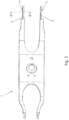
- the Figures 1 , 2 and 3a show a chassis component 1, which is in particular a spring link.
- the chassis component has two opposing base bodies 2, which correspond to the link arms of the spring link.
- the base body 2 has an opening 3 for passing through a fastening means.
- two guide elements 4 are arranged for guiding an eccentric element 5, see Figure 1b ).
- the guide elements 4 are made in one piece by mechanical processing and formed from the same material as the base body 2 of the chassis component 1.
- the guide elements 4 each have a rear side 6 and a contact side 7 facing the opening 3.
- the contact side 7 is formed orthogonally to the base body 2.
- the opening 3 is in the form of an elongated hole.
- the eccentric element 5 has an eccentric screw 8 with an outer collar 9.
- the outer collar 9 of the eccentric element 5 is guided by the guide elements 4 in such a way that when the eccentric element 5 rotates, the eccentric screw 8 moves within the opening 3 and thus the chassis component 1 is displaced.
- the contact sides 7 have a plano-convex shape and the rear sides 6 taper in the opposite direction to the contact sides 7 and merge into the base body 2.
- This design of the guide elements 4 ensures improved robustness of the guide elements 4, enables the guide elements 4 to be designed in the most space-saving way possible and is an optimal shape for the force transmission from the eccentric element 5 to the base body 2.
- Figure 3b shows the guide elements 4 and the base body 2 according to section BB of the Figure 2 .
- the plano-convex contact sides 7 of the guide elements 4 have a height Hk that is less than or equal to the material thickness Sg of the base body 2. This ensures that the guide elements 4 always have a sufficient material thickness.
- Figure 3c shows an alternative design variant of the guide elements 4.
- the side of the contact side 4 facing away from the base body 2 has an at least partially flattened area 10 which runs parallel to the base body 2. In this way, the height Hk of the contact sides 7 and thus of the guide elements 4 can be made as low as possible without reducing the contact surface for the eccentric element 5.
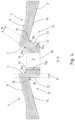
- the guide elements 4 in section AA of the Figure 1b ) are in Figure 4
- an outer transition region 11 with a radius Ra is formed between the respective contact sides 7 and the base body 2.
- the Transition area 11 increases the material thickness between the contact sides 7 and the base body 2.
- the radius Ra is preferably between 0.2 mm and 2 mm, particularly preferably between 0.5 mm and 1.5 mm.
- the base body 2 has a recess 12 below the guide elements 4, as shown in Figure 3a ) and Figure 4 can be seen.
- the indentation 12 is created by the mechanical shaping of the guide elements 4.
- the indentations 12 have a front side 13 and a top side 14, with the front side 13 being arranged parallel to the contact side 7.
- a correspondingly parallel arrangement of the front sides 13 with the contact sides 7 leads to improved stability and robustness of the guide elements 4.
- An orthogonal distance A is formed between the parallel front side 13 and the contact side 7, which corresponds to between 10% and 50% of the material thickness Sg of the base body 2.
- the distance A is particularly preferably between 20% and 40% and particularly preferably between 25% and 35% of the material thickness Sg of the base body 2. This distance A according to the invention ensures a sufficient material thickness between the front side 13 and the contact side 7, which ensures the robustness and service life of the guide elements 4.
- An inner transition area 15 with a radius Ri can be arranged between the front side 13 and the top side 14.
- the inner transition area 15 increases the stability of the guide elements 4 and also reduces the risk of cracks at the transition between the front side 13 and the top side 14.
- the mean vertical cross section of the guide elements 4, as shown in section AA of the Figure 4 shown, has a distance B between the outer transition region 11 and the inner transition region 15.
- the distance B is in particular between 30% and 70% of the material thickness Sg of the base body 2.
- the distance B is between 40% and 60% and particularly preferably between 45% and 55% of the material thickness Sg of the base body 2.
- the distance B is therefore the smallest distance between the outer transition area 11 and the inner transition area 15.
- a length of the distance B according to the invention ensures sufficient material thickness, which increases the robustness and service life of the guide elements 4. No shear cut is required, so that the risk of cracking is reduced.
- the distance B according to the invention can ensure that the fibers within the material structure are not damaged and thus the material thickness is fully maintained. The uninterrupted course of the fibers of the material is in Figure 4 to see.
- the base body 2 has a bottom side 16 in the area of the opening 3.
- a lower transition area 17 with a radius can be formed between the front side 13 and the bottom side 16.
- chassis component 1 can be designed such that the inner transition region 15 merges directly into the lower transition region 17. In this case, no separate front side 13 is formed between the transition regions 15, 17.
- the chassis component 1 is preferably made of an aluminum alloy and is an extruded profile.
- the guide elements 4 are cold-formed. This enables short processing times, good surface quality, tight dimensional tolerances, optimal material utilization and permanent hardening of the material.
- the fiber flow of the material is also not interrupted.
- the opening is designed as an elongated hole.
- the elongated hole enables a corresponding movement of the chassis component 1 by the eccentric element 5.
- the pressure for the forming process is particularly preferably between 5 t and 20 t, in particular between 7.5 t and 13 t. In comparison to similar forming processes for producing guide elements 4, this is an extremely low pressure. This has the advantage that less energy is required for the forming process, and the low contact pressure means that no unwanted notches or other damage to the base body 2 caused by the forming tool 19 remain.
- the oblique orientation of the punch 20 also makes it possible to obtain a material structure that is optimal for the stability of the guide elements 4 through the forming process. In particular, the material fibers are retained, so that the material structure and thus the robustness and strength of the material are not impaired.
- the stamp 20 has a stamp head 24. This is preferably designed such that the contact sides 7 of the guide elements 4 have a plano-convex shape as a result of the molding process and the rear sides 6 taper in the opposite direction to the contact sides 7 and merge into the base body 2.
- the mold recesses 23 of the lower die 21 are also designed accordingly.
- the stamp head 24 is designed such that an inner transition region 15 with a radius Ri is formed by the molding process between the front side 13 and the top side 14.
- the mold recesses 23 of the lower die 21 are preferably designed such that an outer transition region 11 with a radius Ra is formed by the molding process between the contact side 7 and the base body 2.
- the base body 2 preferably has an opening 3 for passing through a fastening means, so that the guide elements 4 are formed on opposite sides of the opening 3 for guiding an eccentric element 5.
- an opening 3 for passing through a fastening means can be created in the base body 2 at the same time as the guide elements 4.
- the guide elements 4 are arranged on opposite sides of the opening 3.
- the guide elements 4 are preferably formed using a cold forming process. This enables short processing times, good surface quality, tight dimensional tolerances, optimal material utilization and permanent hardening of the material.
- the fiber flow of the material is also not interrupted.
- the surfaces of the guide elements 4 are additionally polished after the molding process. This further increases the service life of the chassis component 1.
Landscapes
- Engineering & Computer Science (AREA)
- Mechanical Engineering (AREA)
- Forging (AREA)
Priority Applications (3)
| Application Number | Priority Date | Filing Date | Title |
|---|---|---|---|
| EP22210563.7A EP4378718B1 (fr) | 2022-11-30 | 2022-11-30 | Procédé de fabrication d'un élément de châssis |
| US18/523,336 US12434519B2 (en) | 2022-11-30 | 2023-11-29 | Chassis component and method for producing a chassis component |
| CN202311620526.5A CN118107326A (zh) | 2022-11-30 | 2023-11-30 | 底盘构件和制造底盘构件的方法 |
Applications Claiming Priority (1)
| Application Number | Priority Date | Filing Date | Title |
|---|---|---|---|
| EP22210563.7A EP4378718B1 (fr) | 2022-11-30 | 2022-11-30 | Procédé de fabrication d'un élément de châssis |
Publications (2)
| Publication Number | Publication Date |
|---|---|
| EP4378718A1 true EP4378718A1 (fr) | 2024-06-05 |
| EP4378718B1 EP4378718B1 (fr) | 2025-10-01 |
Family
ID=84367565
Family Applications (1)
| Application Number | Title | Priority Date | Filing Date |
|---|---|---|---|
| EP22210563.7A Active EP4378718B1 (fr) | 2022-11-30 | 2022-11-30 | Procédé de fabrication d'un élément de châssis |
Country Status (3)
| Country | Link |
|---|---|
| US (1) | US12434519B2 (fr) |
| EP (1) | EP4378718B1 (fr) |
| CN (1) | CN118107326A (fr) |
Cited By (1)
| Publication number | Priority date | Publication date | Assignee | Title |
|---|---|---|---|---|
| EP4674649A1 (fr) * | 2024-07-03 | 2026-01-07 | Benteler Automobiltechnik GmbH | Bras de suspension pour véhicule automobile |
Families Citing this family (1)
| Publication number | Priority date | Publication date | Assignee | Title |
|---|---|---|---|---|
| EP4538068B1 (fr) * | 2023-10-10 | 2025-12-17 | Benteler Automobiltechnik GmbH | Bras de suspension pour véhicule automobile |
Citations (9)
| Publication number | Priority date | Publication date | Assignee | Title |
|---|---|---|---|---|
| JPH06247336A (ja) * | 1993-02-26 | 1994-09-06 | Toyota Motor Corp | 位置調整装置 |
| DE19758003A1 (de) * | 1997-01-08 | 1998-08-06 | Volkswagen Ag | Widerlager aus Blech zur Anordnung an einem Träger und Verfahren zur Herstellung |
| EP2783947A1 (fr) * | 2013-03-27 | 2014-10-01 | Audi AG | Dispositif de réglage pour le réglage d'un bras de roue ou d'une barre d'accouplement sur un véhicule automobile et support d'essieu doté d'au moins un tel dispositif de réglage |
| EP2910454A1 (fr) * | 2014-02-20 | 2015-08-26 | Autotech Engineering Deutschland GmbH | Composant de châssis avec butée de disque d'excentrique |
| KR20160140179A (ko) * | 2015-05-29 | 2016-12-07 | 주식회사화신 | 로워암 조립장치 |
| DE102016121131A1 (de) * | 2016-11-04 | 2018-05-09 | Benteler Automobiltechnik Gmbh | Radaufhängungssystem mit einem Lenker |
| DE102020007875A1 (de) * | 2020-12-22 | 2021-03-11 | Dr. Ing. H.C. F. Porsche Aktiengesellschaft | Fahrwerkbauteil |
| US11260715B2 (en) | 2019-07-29 | 2022-03-01 | Benteler Automobiltechnik Gmbh | Chassis component |
| US11338635B2 (en) | 2019-03-19 | 2022-05-24 | Benteler Automobiltechnik Gmbh | Multi-leg control arm for a wheel suspension in a vehicle |
Family Cites Families (7)
| Publication number | Priority date | Publication date | Assignee | Title |
|---|---|---|---|---|
| JP3081587B2 (ja) * | 1998-08-21 | 2000-08-28 | 本田技研工業株式会社 | サスペンションアーム取付構造 |
| US8567772B2 (en) * | 2009-09-22 | 2013-10-29 | Bbs Development, Llc | Adjustable spring mounting assembly |
| MX345694B (es) * | 2012-01-31 | 2017-02-10 | Hendrickson Usa Llc | Disposición de dispositivos de suspensión para sistemas de ejes/suspensión de trabajo pesado. |
| DE102014116077B4 (de) * | 2014-11-04 | 2017-01-19 | Benteler Automobiltechnik Gmbh | Radführungsanordnung für ein Rad eines Fahrzeugs |
| US10017020B2 (en) * | 2015-12-10 | 2018-07-10 | Hendrickson Usa, L.L.C. | Pivotal connection for heavy-duty vehicle suspension assembly |
| DE102016215623A1 (de) * | 2016-08-19 | 2018-02-22 | Volkswagen Aktiengesellschaft | Verfahren zur Herstellung einer Lenker-Lagerungsordnung eines Kraftfahrzeugs sowie Lagerungsanordnung |
| EP4360919B1 (fr) * | 2022-10-31 | 2025-05-14 | Benteler Automobiltechnik GmbH | Bras de suspension à ressort |
-
2022
- 2022-11-30 EP EP22210563.7A patent/EP4378718B1/fr active Active
-
2023
- 2023-11-29 US US18/523,336 patent/US12434519B2/en active Active
- 2023-11-30 CN CN202311620526.5A patent/CN118107326A/zh active Pending
Patent Citations (9)
| Publication number | Priority date | Publication date | Assignee | Title |
|---|---|---|---|---|
| JPH06247336A (ja) * | 1993-02-26 | 1994-09-06 | Toyota Motor Corp | 位置調整装置 |
| DE19758003A1 (de) * | 1997-01-08 | 1998-08-06 | Volkswagen Ag | Widerlager aus Blech zur Anordnung an einem Träger und Verfahren zur Herstellung |
| EP2783947A1 (fr) * | 2013-03-27 | 2014-10-01 | Audi AG | Dispositif de réglage pour le réglage d'un bras de roue ou d'une barre d'accouplement sur un véhicule automobile et support d'essieu doté d'au moins un tel dispositif de réglage |
| EP2910454A1 (fr) * | 2014-02-20 | 2015-08-26 | Autotech Engineering Deutschland GmbH | Composant de châssis avec butée de disque d'excentrique |
| KR20160140179A (ko) * | 2015-05-29 | 2016-12-07 | 주식회사화신 | 로워암 조립장치 |
| DE102016121131A1 (de) * | 2016-11-04 | 2018-05-09 | Benteler Automobiltechnik Gmbh | Radaufhängungssystem mit einem Lenker |
| US11338635B2 (en) | 2019-03-19 | 2022-05-24 | Benteler Automobiltechnik Gmbh | Multi-leg control arm for a wheel suspension in a vehicle |
| US11260715B2 (en) | 2019-07-29 | 2022-03-01 | Benteler Automobiltechnik Gmbh | Chassis component |
| DE102020007875A1 (de) * | 2020-12-22 | 2021-03-11 | Dr. Ing. H.C. F. Porsche Aktiengesellschaft | Fahrwerkbauteil |
Cited By (1)
| Publication number | Priority date | Publication date | Assignee | Title |
|---|---|---|---|---|
| EP4674649A1 (fr) * | 2024-07-03 | 2026-01-07 | Benteler Automobiltechnik GmbH | Bras de suspension pour véhicule automobile |
Also Published As
| Publication number | Publication date |
|---|---|
| EP4378718B1 (fr) | 2025-10-01 |
| CN118107326A (zh) | 2024-05-31 |
| US20240174038A1 (en) | 2024-05-30 |
| US12434519B2 (en) | 2025-10-07 |
Similar Documents
| Publication | Publication Date | Title |
|---|---|---|
| EP2671741B2 (fr) | Bras oscillant transversal et son procédé de fabrication | |
| EP1479842B1 (fr) | Profilé creux | |
| DE112014003031T5 (de) | Schwingungsdämpfungsbuchse und Herstellungsverfahren einer Schwingungsdämpfungsbuchse | |
| DE102014113724A1 (de) | Systeme und Verfahren zur elastisch gemittelten Ausrichtung | |
| EP4378718B1 (fr) | Procédé de fabrication d'un élément de châssis | |
| DE60304725T2 (de) | Treibriemen mit querelementen und stanzvorrichtung zum herstellen von querelementen | |
| WO2004011172A1 (fr) | Dispositif d'arrachage | |
| EP1948959A1 (fr) | Ressort a lames composite, renforce par des fibres, segmente et procede de production associe | |
| WO2014124772A1 (fr) | Procédé d'ajustement d'un jeu axial d'un tourillon monté dans un palier et dispositif comportant un palier et un tourillon monté dans le palier | |
| DE102021103439B3 (de) | Verfahren zur Herstellung eines Dämpferhalters und Dämpferhalter | |
| EP1642037B1 (fr) | Ensemble palier pour un vehicule automobile | |
| EP1107840B1 (fr) | Procede de fabrication de cremaillere et dispositif d'estampage permettant la mise en oeuvre dudit procede | |
| EP1262693B1 (fr) | Tige de commande de fourchettes avec fourchette de commande de changement de vitesses | |
| DE102020105248A1 (de) | Lageranordnung mit einem Kernelement für ein Fahrzeug | |
| DE102018124493B4 (de) | Gelenkgehäuse und Verfahren zur Herstellung eines Gelenkgehäuses | |
| DE112006002662B4 (de) | Blattfeder mit im Querschnitt konvexer Ober-und Unterseite | |
| EP2287484A2 (fr) | Ensemble moyeu-arbre pour la transmission de couple | |
| DE102023101472B4 (de) | Verfahren zur Speichenverstärkung und eine Speichenverstärkungsstruktur | |
| DE102016210458B4 (de) | Torsionsquerträger, insbesondere für eine Verbundlenkerachse und Kraftfahrzeug aufweisend den Torsionsquerträger | |
| EP4703160A1 (fr) | Entretoise de châssis pour véhicules, en particulier véhicules automobiles, et procédé de fabrication d'une telle entretoise de châssis | |
| DE102004031714A1 (de) | Herstellungsverfahren für ein Kupplungselement und insbesondere für eine Gabel eines Kardangelenks, und Kupplungselement, das gemäß diesem Verfahren hergestellt ist | |
| EP3075928B1 (fr) | Poignée interne de porte ayant un contre-poids amélioré | |
| DE102023005407A1 (de) | Verfahren zur Speichenverstärkung und eine Speichenverstärkungsstruktur | |
| DE102020131523A1 (de) | Herstellungsverfahren für ein Band sowie ein Band | |
| DE102019121667A1 (de) | Fahrwerk für ein Nutzfahrzeug, Schale hierfür sowie Anordnung zweier ein Schalenpaar bildender Schalen hierfür |
Legal Events
| Date | Code | Title | Description |
|---|---|---|---|
| PUAI | Public reference made under article 153(3) epc to a published international application that has entered the european phase |
Free format text: ORIGINAL CODE: 0009012 |
|
| STAA | Information on the status of an ep patent application or granted ep patent |
Free format text: STATUS: THE APPLICATION HAS BEEN PUBLISHED |
|
| AK | Designated contracting states |
Kind code of ref document: A1 Designated state(s): AL AT BE BG CH CY CZ DE DK EE ES FI FR GB GR HR HU IE IS IT LI LT LU LV MC ME MK MT NL NO PL PT RO RS SE SI SK SM TR |
|
| STAA | Information on the status of an ep patent application or granted ep patent |
Free format text: STATUS: REQUEST FOR EXAMINATION WAS MADE |
|
| 17P | Request for examination filed |
Effective date: 20241021 |
|
| RBV | Designated contracting states (corrected) |
Designated state(s): AL AT BE BG CH CY CZ DE DK EE ES FI FR GB GR HR HU IE IS IT LI LT LU LV MC ME MK MT NL NO PL PT RO RS SE SI SK SM TR |
|
| GRAP | Despatch of communication of intention to grant a patent |
Free format text: ORIGINAL CODE: EPIDOSNIGR1 |
|
| STAA | Information on the status of an ep patent application or granted ep patent |
Free format text: STATUS: GRANT OF PATENT IS INTENDED |
|
| INTG | Intention to grant announced |
Effective date: 20250625 |
|
| GRAS | Grant fee paid |
Free format text: ORIGINAL CODE: EPIDOSNIGR3 |
|
| GRAA | (expected) grant |
Free format text: ORIGINAL CODE: 0009210 |
|
| STAA | Information on the status of an ep patent application or granted ep patent |
Free format text: STATUS: THE PATENT HAS BEEN GRANTED |
|
| AK | Designated contracting states |
Kind code of ref document: B1 Designated state(s): AL AT BE BG CH CY CZ DE DK EE ES FI FR GB GR HR HU IE IS IT LI LT LU LV MC ME MK MT NL NO PL PT RO RS SE SI SK SM TR |
|
| REG | Reference to a national code |
Ref country code: GB Ref legal event code: FG4D Free format text: NOT ENGLISH Ref country code: CH Ref legal event code: F10 Free format text: ST27 STATUS EVENT CODE: U-0-0-F10-F00 (AS PROVIDED BY THE NATIONAL OFFICE) Effective date: 20251001 |
|
| REG | Reference to a national code |
Ref country code: DE Ref legal event code: R096 Ref document number: 502022005621 Country of ref document: DE |
|
| REG | Reference to a national code |
Ref country code: IE Ref legal event code: FG4D Free format text: LANGUAGE OF EP DOCUMENT: GERMAN |
|
| PGFP | Annual fee paid to national office [announced via postgrant information from national office to epo] |
Ref country code: DE Payment date: 20251127 Year of fee payment: 4 |
|
| PGFP | Annual fee paid to national office [announced via postgrant information from national office to epo] |
Ref country code: NO Payment date: 20251125 Year of fee payment: 4 |
|
| PGFP | Annual fee paid to national office [announced via postgrant information from national office to epo] |
Ref country code: FR Payment date: 20251128 Year of fee payment: 4 |
|
| REG | Reference to a national code |
Ref country code: NL Ref legal event code: MP Effective date: 20251001 |
|
| PG25 | Lapsed in a contracting state [announced via postgrant information from national office to epo] |
Ref country code: NL Free format text: LAPSE BECAUSE OF FAILURE TO SUBMIT A TRANSLATION OF THE DESCRIPTION OR TO PAY THE FEE WITHIN THE PRESCRIBED TIME-LIMIT Effective date: 20251001 |
|
| PG25 | Lapsed in a contracting state [announced via postgrant information from national office to epo] |
Ref country code: ES Free format text: LAPSE BECAUSE OF FAILURE TO SUBMIT A TRANSLATION OF THE DESCRIPTION OR TO PAY THE FEE WITHIN THE PRESCRIBED TIME-LIMIT Effective date: 20251001 |
|
| REG | Reference to a national code |
Ref country code: LT Ref legal event code: MG9D |
|
| PG25 | Lapsed in a contracting state [announced via postgrant information from national office to epo] |
Ref country code: FI Free format text: LAPSE BECAUSE OF FAILURE TO SUBMIT A TRANSLATION OF THE DESCRIPTION OR TO PAY THE FEE WITHIN THE PRESCRIBED TIME-LIMIT Effective date: 20251001 Ref country code: HR Free format text: LAPSE BECAUSE OF FAILURE TO SUBMIT A TRANSLATION OF THE DESCRIPTION OR TO PAY THE FEE WITHIN THE PRESCRIBED TIME-LIMIT Effective date: 20251001 |
|
| PG25 | Lapsed in a contracting state [announced via postgrant information from national office to epo] |
Ref country code: RS Free format text: LAPSE BECAUSE OF FAILURE TO SUBMIT A TRANSLATION OF THE DESCRIPTION OR TO PAY THE FEE WITHIN THE PRESCRIBED TIME-LIMIT Effective date: 20260101 |
|
| PG25 | Lapsed in a contracting state [announced via postgrant information from national office to epo] |
Ref country code: IS Free format text: LAPSE BECAUSE OF FAILURE TO SUBMIT A TRANSLATION OF THE DESCRIPTION OR TO PAY THE FEE WITHIN THE PRESCRIBED TIME-LIMIT Effective date: 20260201 |