EP4378729A1 - Procédé et appareil de commande de dérive de véhicule, véhicule, support d'informations et puce - Google Patents
Procédé et appareil de commande de dérive de véhicule, véhicule, support d'informations et puce Download PDFInfo
- Publication number
- EP4378729A1 EP4378729A1 EP23176478.8A EP23176478A EP4378729A1 EP 4378729 A1 EP4378729 A1 EP 4378729A1 EP 23176478 A EP23176478 A EP 23176478A EP 4378729 A1 EP4378729 A1 EP 4378729A1
- Authority
- EP
- European Patent Office
- Prior art keywords
- vehicle
- steering
- drift
- target
- torque
- Prior art date
- Legal status (The legal status is an assumption and is not a legal conclusion. Google has not performed a legal analysis and makes no representation as to the accuracy of the status listed.)
- Granted
Links
Images



Classifications
-
- B—PERFORMING OPERATIONS; TRANSPORTING
- B62—LAND VEHICLES FOR TRAVELLING OTHERWISE THAN ON RAILS
- B62D—MOTOR VEHICLES; TRAILERS
- B62D6/00—Arrangements for automatically controlling steering depending on driving conditions sensed and responded to, e.g. control circuits
- B62D6/002—Arrangements for automatically controlling steering depending on driving conditions sensed and responded to, e.g. control circuits computing target steering angles for front or rear wheels
- B62D6/006—Arrangements for automatically controlling steering depending on driving conditions sensed and responded to, e.g. control circuits computing target steering angles for front or rear wheels using a measured or estimated road friction coefficient
-
- B—PERFORMING OPERATIONS; TRANSPORTING
- B60—VEHICLES IN GENERAL
- B60W—CONJOINT CONTROL OF VEHICLE SUB-UNITS OF DIFFERENT TYPE OR DIFFERENT FUNCTION; CONTROL SYSTEMS SPECIALLY ADAPTED FOR HYBRID VEHICLES; ROAD VEHICLE DRIVE CONTROL SYSTEMS FOR PURPOSES NOT RELATED TO THE CONTROL OF A PARTICULAR SUB-UNIT
- B60W10/00—Conjoint control of vehicle sub-units of different type or different function
- B60W10/18—Conjoint control of vehicle sub-units of different type or different function including control of braking systems
-
- B—PERFORMING OPERATIONS; TRANSPORTING
- B60—VEHICLES IN GENERAL
- B60W—CONJOINT CONTROL OF VEHICLE SUB-UNITS OF DIFFERENT TYPE OR DIFFERENT FUNCTION; CONTROL SYSTEMS SPECIALLY ADAPTED FOR HYBRID VEHICLES; ROAD VEHICLE DRIVE CONTROL SYSTEMS FOR PURPOSES NOT RELATED TO THE CONTROL OF A PARTICULAR SUB-UNIT
- B60W10/00—Conjoint control of vehicle sub-units of different type or different function
- B60W10/20—Conjoint control of vehicle sub-units of different type or different function including control of steering systems
-
- B—PERFORMING OPERATIONS; TRANSPORTING
- B60—VEHICLES IN GENERAL
- B60W—CONJOINT CONTROL OF VEHICLE SUB-UNITS OF DIFFERENT TYPE OR DIFFERENT FUNCTION; CONTROL SYSTEMS SPECIALLY ADAPTED FOR HYBRID VEHICLES; ROAD VEHICLE DRIVE CONTROL SYSTEMS FOR PURPOSES NOT RELATED TO THE CONTROL OF A PARTICULAR SUB-UNIT
- B60W40/00—Estimation or calculation of non-directly measurable driving parameters for road vehicle drive control systems not related to the control of a particular sub unit, e.g. by using mathematical models
- B60W40/10—Estimation or calculation of non-directly measurable driving parameters for road vehicle drive control systems not related to the control of a particular sub unit, e.g. by using mathematical models related to vehicle motion
- B60W40/101—Side slip angle of tyre
-
- B—PERFORMING OPERATIONS; TRANSPORTING
- B60—VEHICLES IN GENERAL
- B60W—CONJOINT CONTROL OF VEHICLE SUB-UNITS OF DIFFERENT TYPE OR DIFFERENT FUNCTION; CONTROL SYSTEMS SPECIALLY ADAPTED FOR HYBRID VEHICLES; ROAD VEHICLE DRIVE CONTROL SYSTEMS FOR PURPOSES NOT RELATED TO THE CONTROL OF A PARTICULAR SUB-UNIT
- B60W40/00—Estimation or calculation of non-directly measurable driving parameters for road vehicle drive control systems not related to the control of a particular sub unit, e.g. by using mathematical models
- B60W40/10—Estimation or calculation of non-directly measurable driving parameters for road vehicle drive control systems not related to the control of a particular sub unit, e.g. by using mathematical models related to vehicle motion
- B60W40/114—Yaw movement
-
- B—PERFORMING OPERATIONS; TRANSPORTING
- B60—VEHICLES IN GENERAL
- B60W—CONJOINT CONTROL OF VEHICLE SUB-UNITS OF DIFFERENT TYPE OR DIFFERENT FUNCTION; CONTROL SYSTEMS SPECIALLY ADAPTED FOR HYBRID VEHICLES; ROAD VEHICLE DRIVE CONTROL SYSTEMS FOR PURPOSES NOT RELATED TO THE CONTROL OF A PARTICULAR SUB-UNIT
- B60W50/00—Details of control systems for road vehicle drive control not related to the control of a particular sub-unit, e.g. process diagnostic or vehicle driver interfaces
- B60W50/08—Interaction between the driver and the control system
- B60W50/14—Means for informing the driver, warning the driver or prompting a driver intervention
-
- B—PERFORMING OPERATIONS; TRANSPORTING
- B60—VEHICLES IN GENERAL
- B60K—ARRANGEMENT OR MOUNTING OF PROPULSION UNITS OR OF TRANSMISSIONS IN VEHICLES; ARRANGEMENT OR MOUNTING OF PLURAL DIVERSE PRIME-MOVERS IN VEHICLES; AUXILIARY DRIVES FOR VEHICLES; INSTRUMENTATION OR DASHBOARDS FOR VEHICLES; ARRANGEMENTS IN CONNECTION WITH COOLING, AIR INTAKE, GAS EXHAUST OR FUEL SUPPLY OF PROPULSION UNITS IN VEHICLES
- B60K6/00—Arrangement or mounting of plural diverse prime-movers for mutual or common propulsion, e.g. hybrid propulsion systems comprising electric motors and internal combustion engines
- B60K6/20—Arrangement or mounting of plural diverse prime-movers for mutual or common propulsion, e.g. hybrid propulsion systems comprising electric motors and internal combustion engines the prime-movers consisting of electric motors and internal combustion engines, e.g. HEVs
- B60K6/50—Architecture of the driveline characterised by arrangement or kind of transmission units
- B60K6/52—Driving a plurality of drive axles, e.g. four-wheel drive
-
- B—PERFORMING OPERATIONS; TRANSPORTING
- B60—VEHICLES IN GENERAL
- B60W—CONJOINT CONTROL OF VEHICLE SUB-UNITS OF DIFFERENT TYPE OR DIFFERENT FUNCTION; CONTROL SYSTEMS SPECIALLY ADAPTED FOR HYBRID VEHICLES; ROAD VEHICLE DRIVE CONTROL SYSTEMS FOR PURPOSES NOT RELATED TO THE CONTROL OF A PARTICULAR SUB-UNIT
- B60W10/00—Conjoint control of vehicle sub-units of different type or different function
- B60W10/04—Conjoint control of vehicle sub-units of different type or different function including control of propulsion units
-
- B—PERFORMING OPERATIONS; TRANSPORTING
- B60—VEHICLES IN GENERAL
- B60W—CONJOINT CONTROL OF VEHICLE SUB-UNITS OF DIFFERENT TYPE OR DIFFERENT FUNCTION; CONTROL SYSTEMS SPECIALLY ADAPTED FOR HYBRID VEHICLES; ROAD VEHICLE DRIVE CONTROL SYSTEMS FOR PURPOSES NOT RELATED TO THE CONTROL OF A PARTICULAR SUB-UNIT
- B60W10/00—Conjoint control of vehicle sub-units of different type or different function
- B60W10/12—Conjoint control of vehicle sub-units of different type or different function including control of differentials
- B60W10/14—Central differentials for dividing torque between front and rear axles
-
- B—PERFORMING OPERATIONS; TRANSPORTING
- B60—VEHICLES IN GENERAL
- B60W—CONJOINT CONTROL OF VEHICLE SUB-UNITS OF DIFFERENT TYPE OR DIFFERENT FUNCTION; CONTROL SYSTEMS SPECIALLY ADAPTED FOR HYBRID VEHICLES; ROAD VEHICLE DRIVE CONTROL SYSTEMS FOR PURPOSES NOT RELATED TO THE CONTROL OF A PARTICULAR SUB-UNIT
- B60W50/00—Details of control systems for road vehicle drive control not related to the control of a particular sub-unit, e.g. process diagnostic or vehicle driver interfaces
- B60W2050/0001—Details of the control system
- B60W2050/0002—Automatic control, details of type of controller or control system architecture
- B60W2050/0008—Feedback, closed loop systems or details of feedback error signal
- B60W2050/0011—Proportional Integral Differential [PID] controller
-
- B—PERFORMING OPERATIONS; TRANSPORTING
- B60—VEHICLES IN GENERAL
- B60W—CONJOINT CONTROL OF VEHICLE SUB-UNITS OF DIFFERENT TYPE OR DIFFERENT FUNCTION; CONTROL SYSTEMS SPECIALLY ADAPTED FOR HYBRID VEHICLES; ROAD VEHICLE DRIVE CONTROL SYSTEMS FOR PURPOSES NOT RELATED TO THE CONTROL OF A PARTICULAR SUB-UNIT
- B60W2510/00—Input parameters relating to a particular sub-units
- B60W2510/20—Steering systems
-
- B—PERFORMING OPERATIONS; TRANSPORTING
- B60—VEHICLES IN GENERAL
- B60W—CONJOINT CONTROL OF VEHICLE SUB-UNITS OF DIFFERENT TYPE OR DIFFERENT FUNCTION; CONTROL SYSTEMS SPECIALLY ADAPTED FOR HYBRID VEHICLES; ROAD VEHICLE DRIVE CONTROL SYSTEMS FOR PURPOSES NOT RELATED TO THE CONTROL OF A PARTICULAR SUB-UNIT
- B60W2520/00—Input parameters relating to overall vehicle dynamics
- B60W2520/10—Longitudinal speed
-
- B—PERFORMING OPERATIONS; TRANSPORTING
- B60—VEHICLES IN GENERAL
- B60W—CONJOINT CONTROL OF VEHICLE SUB-UNITS OF DIFFERENT TYPE OR DIFFERENT FUNCTION; CONTROL SYSTEMS SPECIALLY ADAPTED FOR HYBRID VEHICLES; ROAD VEHICLE DRIVE CONTROL SYSTEMS FOR PURPOSES NOT RELATED TO THE CONTROL OF A PARTICULAR SUB-UNIT
- B60W2520/00—Input parameters relating to overall vehicle dynamics
- B60W2520/14—Yaw
-
- B—PERFORMING OPERATIONS; TRANSPORTING
- B60—VEHICLES IN GENERAL
- B60W—CONJOINT CONTROL OF VEHICLE SUB-UNITS OF DIFFERENT TYPE OR DIFFERENT FUNCTION; CONTROL SYSTEMS SPECIALLY ADAPTED FOR HYBRID VEHICLES; ROAD VEHICLE DRIVE CONTROL SYSTEMS FOR PURPOSES NOT RELATED TO THE CONTROL OF A PARTICULAR SUB-UNIT
- B60W2520/00—Input parameters relating to overall vehicle dynamics
- B60W2520/26—Wheel slip
-
- B—PERFORMING OPERATIONS; TRANSPORTING
- B60—VEHICLES IN GENERAL
- B60W—CONJOINT CONTROL OF VEHICLE SUB-UNITS OF DIFFERENT TYPE OR DIFFERENT FUNCTION; CONTROL SYSTEMS SPECIALLY ADAPTED FOR HYBRID VEHICLES; ROAD VEHICLE DRIVE CONTROL SYSTEMS FOR PURPOSES NOT RELATED TO THE CONTROL OF A PARTICULAR SUB-UNIT
- B60W2520/00—Input parameters relating to overall vehicle dynamics
- B60W2520/26—Wheel slip
- B60W2520/263—Slip values between front and rear axle
-
- B—PERFORMING OPERATIONS; TRANSPORTING
- B60—VEHICLES IN GENERAL
- B60W—CONJOINT CONTROL OF VEHICLE SUB-UNITS OF DIFFERENT TYPE OR DIFFERENT FUNCTION; CONTROL SYSTEMS SPECIALLY ADAPTED FOR HYBRID VEHICLES; ROAD VEHICLE DRIVE CONTROL SYSTEMS FOR PURPOSES NOT RELATED TO THE CONTROL OF A PARTICULAR SUB-UNIT
- B60W2540/00—Input parameters relating to occupants
- B60W2540/18—Steering angle
-
- B—PERFORMING OPERATIONS; TRANSPORTING
- B60—VEHICLES IN GENERAL
- B60W—CONJOINT CONTROL OF VEHICLE SUB-UNITS OF DIFFERENT TYPE OR DIFFERENT FUNCTION; CONTROL SYSTEMS SPECIALLY ADAPTED FOR HYBRID VEHICLES; ROAD VEHICLE DRIVE CONTROL SYSTEMS FOR PURPOSES NOT RELATED TO THE CONTROL OF A PARTICULAR SUB-UNIT
- B60W2540/00—Input parameters relating to occupants
- B60W2540/215—Selection or confirmation of options
-
- B—PERFORMING OPERATIONS; TRANSPORTING
- B60—VEHICLES IN GENERAL
- B60W—CONJOINT CONTROL OF VEHICLE SUB-UNITS OF DIFFERENT TYPE OR DIFFERENT FUNCTION; CONTROL SYSTEMS SPECIALLY ADAPTED FOR HYBRID VEHICLES; ROAD VEHICLE DRIVE CONTROL SYSTEMS FOR PURPOSES NOT RELATED TO THE CONTROL OF A PARTICULAR SUB-UNIT
- B60W2540/00—Input parameters relating to occupants
- B60W2540/30—Driving style
-
- B—PERFORMING OPERATIONS; TRANSPORTING
- B60—VEHICLES IN GENERAL
- B60W—CONJOINT CONTROL OF VEHICLE SUB-UNITS OF DIFFERENT TYPE OR DIFFERENT FUNCTION; CONTROL SYSTEMS SPECIALLY ADAPTED FOR HYBRID VEHICLES; ROAD VEHICLE DRIVE CONTROL SYSTEMS FOR PURPOSES NOT RELATED TO THE CONTROL OF A PARTICULAR SUB-UNIT
- B60W2710/00—Output or target parameters relating to a particular sub-units
- B60W2710/18—Braking system
-
- B—PERFORMING OPERATIONS; TRANSPORTING
- B60—VEHICLES IN GENERAL
- B60W—CONJOINT CONTROL OF VEHICLE SUB-UNITS OF DIFFERENT TYPE OR DIFFERENT FUNCTION; CONTROL SYSTEMS SPECIALLY ADAPTED FOR HYBRID VEHICLES; ROAD VEHICLE DRIVE CONTROL SYSTEMS FOR PURPOSES NOT RELATED TO THE CONTROL OF A PARTICULAR SUB-UNIT
- B60W2710/00—Output or target parameters relating to a particular sub-units
- B60W2710/20—Steering systems
-
- B—PERFORMING OPERATIONS; TRANSPORTING
- B60—VEHICLES IN GENERAL
- B60W—CONJOINT CONTROL OF VEHICLE SUB-UNITS OF DIFFERENT TYPE OR DIFFERENT FUNCTION; CONTROL SYSTEMS SPECIALLY ADAPTED FOR HYBRID VEHICLES; ROAD VEHICLE DRIVE CONTROL SYSTEMS FOR PURPOSES NOT RELATED TO THE CONTROL OF A PARTICULAR SUB-UNIT
- B60W2710/00—Output or target parameters relating to a particular sub-units
- B60W2710/20—Steering systems
- B60W2710/207—Steering angle of wheels
-
- B—PERFORMING OPERATIONS; TRANSPORTING
- B60—VEHICLES IN GENERAL
- B60W—CONJOINT CONTROL OF VEHICLE SUB-UNITS OF DIFFERENT TYPE OR DIFFERENT FUNCTION; CONTROL SYSTEMS SPECIALLY ADAPTED FOR HYBRID VEHICLES; ROAD VEHICLE DRIVE CONTROL SYSTEMS FOR PURPOSES NOT RELATED TO THE CONTROL OF A PARTICULAR SUB-UNIT
- B60W2720/00—Output or target parameters relating to overall vehicle dynamics
- B60W2720/14—Yaw
-
- B—PERFORMING OPERATIONS; TRANSPORTING
- B60—VEHICLES IN GENERAL
- B60W—CONJOINT CONTROL OF VEHICLE SUB-UNITS OF DIFFERENT TYPE OR DIFFERENT FUNCTION; CONTROL SYSTEMS SPECIALLY ADAPTED FOR HYBRID VEHICLES; ROAD VEHICLE DRIVE CONTROL SYSTEMS FOR PURPOSES NOT RELATED TO THE CONTROL OF A PARTICULAR SUB-UNIT
- B60W2720/00—Output or target parameters relating to overall vehicle dynamics
- B60W2720/40—Torque distribution
- B60W2720/403—Torque distribution between front and rear axle
-
- B—PERFORMING OPERATIONS; TRANSPORTING
- B60—VEHICLES IN GENERAL
- B60W—CONJOINT CONTROL OF VEHICLE SUB-UNITS OF DIFFERENT TYPE OR DIFFERENT FUNCTION; CONTROL SYSTEMS SPECIALLY ADAPTED FOR HYBRID VEHICLES; ROAD VEHICLE DRIVE CONTROL SYSTEMS FOR PURPOSES NOT RELATED TO THE CONTROL OF A PARTICULAR SUB-UNIT
- B60W30/00—Purposes of road vehicle drive control systems not related to the control of a particular sub-unit, e.g. of systems using conjoint control of vehicle sub-units
- B60W30/02—Control of vehicle driving stability
- B60W30/045—Improving turning performance
-
- B—PERFORMING OPERATIONS; TRANSPORTING
- B60—VEHICLES IN GENERAL
- B60W—CONJOINT CONTROL OF VEHICLE SUB-UNITS OF DIFFERENT TYPE OR DIFFERENT FUNCTION; CONTROL SYSTEMS SPECIALLY ADAPTED FOR HYBRID VEHICLES; ROAD VEHICLE DRIVE CONTROL SYSTEMS FOR PURPOSES NOT RELATED TO THE CONTROL OF A PARTICULAR SUB-UNIT
- B60W30/00—Purposes of road vehicle drive control systems not related to the control of a particular sub-unit, e.g. of systems using conjoint control of vehicle sub-units
- B60W30/18—Propelling the vehicle
- B60W30/18009—Propelling the vehicle related to particular drive situations
- B60W30/18072—Coasting
-
- B—PERFORMING OPERATIONS; TRANSPORTING
- B60—VEHICLES IN GENERAL
- B60W—CONJOINT CONTROL OF VEHICLE SUB-UNITS OF DIFFERENT TYPE OR DIFFERENT FUNCTION; CONTROL SYSTEMS SPECIALLY ADAPTED FOR HYBRID VEHICLES; ROAD VEHICLE DRIVE CONTROL SYSTEMS FOR PURPOSES NOT RELATED TO THE CONTROL OF A PARTICULAR SUB-UNIT
- B60W30/00—Purposes of road vehicle drive control systems not related to the control of a particular sub-unit, e.g. of systems using conjoint control of vehicle sub-units
- B60W30/18—Propelling the vehicle
- B60W30/18009—Propelling the vehicle related to particular drive situations
- B60W30/18145—Cornering
-
- B—PERFORMING OPERATIONS; TRANSPORTING
- B60—VEHICLES IN GENERAL
- B60W—CONJOINT CONTROL OF VEHICLE SUB-UNITS OF DIFFERENT TYPE OR DIFFERENT FUNCTION; CONTROL SYSTEMS SPECIALLY ADAPTED FOR HYBRID VEHICLES; ROAD VEHICLE DRIVE CONTROL SYSTEMS FOR PURPOSES NOT RELATED TO THE CONTROL OF A PARTICULAR SUB-UNIT
- B60W30/00—Purposes of road vehicle drive control systems not related to the control of a particular sub-unit, e.g. of systems using conjoint control of vehicle sub-units
- B60W30/18—Propelling the vehicle
- B60W30/182—Selecting between different operative modes, e.g. comfort and performance modes
-
- B—PERFORMING OPERATIONS; TRANSPORTING
- B60—VEHICLES IN GENERAL
- B60W—CONJOINT CONTROL OF VEHICLE SUB-UNITS OF DIFFERENT TYPE OR DIFFERENT FUNCTION; CONTROL SYSTEMS SPECIALLY ADAPTED FOR HYBRID VEHICLES; ROAD VEHICLE DRIVE CONTROL SYSTEMS FOR PURPOSES NOT RELATED TO THE CONTROL OF A PARTICULAR SUB-UNIT
- B60W40/00—Estimation or calculation of non-directly measurable driving parameters for road vehicle drive control systems not related to the control of a particular sub unit, e.g. by using mathematical models
- B60W40/10—Estimation or calculation of non-directly measurable driving parameters for road vehicle drive control systems not related to the control of a particular sub unit, e.g. by using mathematical models related to vehicle motion
- B60W40/103—Side slip angle of vehicle body
-
- Y—GENERAL TAGGING OF NEW TECHNOLOGICAL DEVELOPMENTS; GENERAL TAGGING OF CROSS-SECTIONAL TECHNOLOGIES SPANNING OVER SEVERAL SECTIONS OF THE IPC; TECHNICAL SUBJECTS COVERED BY FORMER USPC CROSS-REFERENCE ART COLLECTIONS [XRACs] AND DIGESTS
- Y02—TECHNOLOGIES OR APPLICATIONS FOR MITIGATION OR ADAPTATION AGAINST CLIMATE CHANGE
- Y02T—CLIMATE CHANGE MITIGATION TECHNOLOGIES RELATED TO TRANSPORTATION
- Y02T10/00—Road transport of goods or passengers
- Y02T10/60—Other road transportation technologies with climate change mitigation effect
- Y02T10/72—Electric energy management in electromobility
Definitions
- the disclosure relates to the technical field of vehicle control, in particular to a vehicle drift control method and apparatus, a vehicle, a storage medium and a chip.
- Vehicle drift depends on driver's proficiency in joint operation of an accelerator, steering, brake, etc.
- the disclosure provides a vehicle drift control method and apparatus, a vehicle, a storage medium and a chip.
- a vehicle drift control method including:
- the step of determining the target drift parameter according to the slip rate level, the steering information and the current vehicle velocity of the vehicle includes:
- the vehicle drift control method includes:
- the target drift parameter further includes at least one of a target rear axle side slip angle, a target front axle slip rate, a target rear axle slip rate or a target wheel velocity.
- the steering information includes an actual steering angle and a steering direction
- the target drift parameter includes the target wheel velocity
- the step of determining the front axle torque, the rear axle torque and the rear wheel brake torque of the vehicle according to the steering compensation quantity and the steering information includes:
- the step of controlling the vehicle to drift according to the front axle torque, the rear axle torque and the rear wheel brake torque includes: controlling the front axle drive motor of the vehicle to provide the front axle torque for a front wheel, controlling the rear axle drive motor of the vehicle to provide the rear axle torque for a rear wheel, and controlling a brake system of the vehicle to provide the rear wheel brake torque for the target rear wheel, so as to control the vehicle to drift.
- the method before the step of controlling the power-assisted steering motor to perform steering compensation according to the steering compensation quantity and the current vehicle velocity, the method includes:
- the vehicle drift control method further includes:
- the step of determining the steering compensation quantity according to the current actual yaw rate of the vehicle and the target yaw rate includes:
- a vehicle drift control apparatus including:
- the first determining module is configured to:
- the first determining module is configured to:
- the target drift parameter further includes at least one of a target rear axle side slip angle, a target front axle slip rate, a target rear axle slip rate or a target wheel velocity.
- the steering information includes an actual steering angle and a steering direction
- the target drift parameter includes the target wheel velocity
- the third determining module is configured to:
- control module is configured to: control the front axle drive motor of the vehicle to provide the front axle torque for a front wheel, control the rear axle drive motor of the vehicle to provide the rear axle torque for a rear wheel, and control a brake system of the vehicle to provide the rear wheel brake torque for the target rear wheel, so as to control the vehicle to drift.
- control module is configured to calculate a steering angle difference between the actual steering angle in the steering information and the target steering angle in the target drift parameter before the step of controlling the power-assisted steering motor to perform steering compensation according to the steering compensation quantity and the current vehicle velocity;
- the second determining module is configured to:
- a vehicle including:
- a non-transitory computer readable storage medium on which a computer program instruction is stored, and when the program instruction is executed by a second processor, steps of any one of methods in the first aspect are achieved.
- a chip including a third processor and an interface, where the third processor is configured to read an instruction to execute any one of methods in the first aspect.
- Technical solutions provided by the examples of the disclosure may include following beneficial effects: acquiring the slip rate level and the steering information of the vehicle, when the vehicle is in the activated drift mode state; determining the target drift parameter according to the slip rate level, the steering information and the current vehicle velocity of the vehicle, the target drift parameter includes the target yaw rate; determining the steering compensation quantity according to the current actual yaw rate and the target yaw rate of the vehicle; determining the front axle torque, the rear axle torque and the rear wheel brake torque of the vehicle according to the steering compensation quantity and the steering information; and controlling the vehicle to drift according to the front axle torque, the rear axle torque and the rear wheel brake torque, and controlling the power-assisted steering motor to perform the steering compensation according to the steering compensation quantity and the current vehicle velocity in the drift process.
- different drift parameters may further be determined according to different steering and velocities of the vehicle, and drift in different states is achieved.
- a front axle and a rear axle may both output torque, a torque proportion may not be freely adjusted, and when a side acceleration is relatively large, because of lateral load transfer of a vehicle, a vertical load of an inner wheel is reduced, and the tire force is reduced, which easily breaks the road limit and skids. Since a differential mechanism is in velocity going down and force staying the same, rear axle drive torque is reduced, which makes it difficult for the vehicle to achieve drift.
- the disclosure provides a technical solution related to the field of vehicle control, and in particular to a vehicle drift control method and apparatus, a vehicle, a storage medium and a chip.
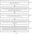
- Fig. 1 is a flow diagram of a vehicle drift control method shown according to an example, and the method may be performed by a whole vehicle central domain controller, as shown in Fig. 1 , including the following steps.
- step S 11 a slip rate level and steering information of a vehicle in a drift mode opening state of the vehicle are acquired.
- a physical drift mode activation switch may be arranged in a center console in a cab or other positions, and a virtual drift mode activation button may also be arranged on a center control display screen, so that a driver may manually activate a drift mode.
- a slip rate level switch may also be arranged, and the slip rate level may be manually selected through the slip rate level switch. For example, 5 levels of slip rates may be set. Vehicle drift velocities, vehicle drift angles, etc. corresponding to different levels of slip rates are all different.
- the drift mode of the vehicle enters in a standby state in a case that the drift mode activation switch is turned on, such that the slip rate level and the steering information of the vehicle are acquired, and the drift mode of the vehicle enters in an active state in a case that a final vehicle velocity, a steering angle, etc. meet a corresponding condition.
- a target drift parameter is determined according to the slip rate level, the steering information and a current vehicle velocity of the vehicle, and the target drift parameter includes a target yaw rate.
- the vehicle velocity of the vehicle may be collected through a gyroscope or inertial measurement unit.
- step S12 the step of determining the target drift parameter according to the slip rate level, the steering information and the current vehicle velocity of the vehicle may include:
- step S121 a slip rate threshold range of each wheel of the vehicle is determined according to the slip rate level.
- different slip rate levels have a one-to-one correspondence relation with the slip rate threshold ranges, the greater a slip rate threshold value in the slip rate threshold range, the greater the vehicle velocity of the vehicle in drift, and the smaller the slip rate threshold value in the slip rate threshold range, the smaller the vehicle velocity of the vehicle in drift.
- slip rate threshold range here is a range is that the vehicle may realize drift just when the vehicle reaches a large enough velocity, and it may be understood that different slip rate levels are supposed to correspond to a minimum slip rate threshold and a maximum slip rate threshold in vehicle drift.
- step S122 a current actual slip rate of the vehicle is calculated according to the current vehicle velocity of the vehicle.
- u is the current vehicle velocity of the vehicle
- w is a rolling radius of the wheels of the vehicle
- r is radii of the wheels of the vehicle.
- step S123 a target drift parameter is determined according to the steering information and the current vehicle velocity of the vehicle in the case that the actual slip rate is in the slip rate threshold range.
- the target drift parameter is determined according to the steering information and the current vehicle velocity of the vehicle in the case that the actual slip rate is in the slip rate threshold range, that is the actual slip rate is greater than or equal to a minimum slip rate threshold range and less than or equal to a maximum slip rate threshold range.
- a corresponding relation among the steering information, the vehicle velocity and the drift parameter under each slip rate level is pre-calibrated, and the target drift parameter further includes at least one of a target rear axle side slip angle, a target front axle slip rate, a target rear axle slip rate or a target wheel velocity.
- a corresponding relation between the slip rate level and the slip rate threshold range is pre-calibrated, meanwhile, a corresponding relation among the steering information, the vehicle velocity and the drift parameter under each slip rate level is calibrated, a look-up table is obtained, and then in an actual drift control process, the table is looked up according to the slip rate level, the steering information and the vehicle velocity in real time, so as to obtain a target drift parameter corresponding to each moment.
- the vehicle drift control method includes: in step S124, torque output of a front axle drive motor and a rear axle drive motor is controlled in the case that the actual slip rate is out of the slip rate threshold range.
- the torque output of the front axle drive motor and the rear axle drive motor of the vehicle is controlled to be increased in the case that the actual slip rate is smaller than the minimum slip rate threshold range, and the torque output of the front axle drive motor and the rear axle drive motor of the vehicle is controlled to be decreased in the case that the actual slip rate is greater than the maximum slip rate threshold range.
- step S125 the steps of calculating the current actual slip rate of the vehicle according to the current vehicle velocity of the vehicle and controlling the torque output of the front axle drive motor and the rear axle drive motor of the vehicle are repeatedly executed until the actual slip rate is in the slip rate threshold range, and the target drift parameter is determined according to the steering information and the current vehicle velocity of the vehicle.
- step S13 a steering compensation quantity is determined according to the current actual yaw rate of the vehicle and the target yaw rate.
- the actual yaw rate may be determined through a gyroscope or inertial measurement unit arranged on the vehicle, for example, time integration is performed on an angle collected by the gyroscope or inertial measurement unit to determine the current actual yaw rate of the vehicle.
- PID proportion integral differential
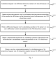
- step S13 the step of determining the steering compensation quantity according to the current actual yaw rate of the vehicle and the target yaw rate includes:
- ⁇ Yawrate is the angular rate difference between the actual yaw rate and the target yaw rate
- P is the differential control sub-parameter in the PID closed-loop control
- I is the proportional control sub-parameter in the PID closed-loop control
- dt is the integration on time t
- Yawrate is the actual yaw rate
- D is the proportional control sub-parameter in the PID closed-loop control.
- step S14 front axle torque, rear axle torque and rear wheel brake torque of the vehicle are determined according to the steering compensation quantity and the steering information.
- the front axle torque and the rear axle torque may be proportionally distributed in an initial state, for example, the front axle torque and the rear axle torque may be distributed at 1:4 in the initial state, and then proportional distribution of the front axle torque and the rear axle torque of the vehicle at each moment in the closed-loop control is determined according to the steering compensation quantity and the steering information.
- the steering information includes an actual steering angle and a steering direction
- the target drift parameter includes a target wheel velocity
- the step of determining the front axle torque, the rear axle torque and the rear wheel brake torque of the vehicle according to the steering compensation quantity and the steering information includes:
- step S141 the front axle torque and the rear axle torque of the vehicle are determined according to the steering compensation quantity and the steering angle.
- a torque distribution proportion of the front axle torque and the rear axle torque is determined according to the steering compensation quantity and the steering angle, and then the front axle torque and the rear axle torque of the vehicle are determined according to total motor torque and the torque distribution proportion.
- step S142 a rear wheel of the vehicle currently located on a drift inner side is taken as a target rear wheel according to the steering direction.
- step S143 rear wheel brake torque for the target rear wheel is determined according to the current wheel velocity of the vehicle and the target wheel velocity.
- the rear wheel brake torque for the target rear wheel is determined according to a wheel velocity difference between the current wheel velocity of the vehicle and the target wheel velocity, brake output is performed through a brake system like brake calipers of the vehicle, and then the rear wheel brake torque is continuously calculated under the PID closed-loop control.
- the rear wheel brake torque for the target rear wheel is determined according to the current wheel velocity and the target wheel velocity in the above technical solution, the target rear wheel may recover the rear axle drive force after brake intervention is increased, and a probability of the vehicle drift failure is reduced.
- step S15 drift of the vehicle is controlled according to the front axle torque, the rear axle torque and the rear wheel brake torque, and a power-assisted steering motor is controlled to perform steering compensation according to the steering compensation quantity and the current vehicle velocity in the drift process.
- a coefficient of road adhesion is estimated, then, a front axle torque limit threshold is calculated according to the coefficient of road adhesion and a front axle target slip rate, and the front axle torque is limited in a range of the front axle torque limit threshold, so that the front axle torque is greater than a minimum value of the front axle torque limit threshold and less than a maximum value of the front axle torque limit threshold.
- the step of controlling drift of the vehicle according to the front axle torque, the rear axle torque and the rear wheel brake torque includes:
- the front axle drive motor of the vehicle is controlled to provide the front axle torque for the front wheel
- the rear axle drive motor of the vehicle is controlled to provide the rear axle torque for the rear wheel
- the brake system of the vehicle is controlled to provide the rear wheel brake torque for the target rear wheel, so as to control the vehicle to drift.
- a corresponding relation among the steering compensation quantity, the vehicle velocity and the target steering torque is pre-calibrated to obtain a power-assisted steering table, then, current target steering torque is obtained by looking up the table according to the steering compensation quantity and the vehicle velocity, and the power-assisted steering motor is controlled to perform steering compensation according to the target steering torque.
- the front axle drive motor and the rear axle drive motor execute the torque to assist the driver in performing drift control; and meanwhile, brake control over the target rear wheel is performed, the PID closed-loop control is performed through the difference between the actual wheel velocity and the target wheel velocity to output the brake torque, and the slip wheel velocity of the target rear wheel is reduced, so that the drive torque will not be reduced because of wheel slip.
- the above technical solution acquires the slip rate level and the steering information of the vehicle in the drift mode opening state of the vehicle; determines the target drift parameter according to the slip rate level, the steering information and the current vehicle velocity of the vehicle, the target drift parameter includes the target yaw rate; determines the steering compensation quantity according to the current actual yaw rate and the target yaw rate of the vehicle; determines the front axle torque, the rear axle torque and the rear wheel brake torque of the vehicle according to the steering compensation quantity and the steering information; and controls the vehicle to drift according to the front axle torque, the rear axle torque and the rear wheel brake torque, and controls the power-assisted steering motor to perform steering compensation according to the steering compensation quantity and the current vehicle velocity in the drift process.
- different drift parameters may further be determined according to different steering and velocities of the vehicle, and drift in different states is achieved.
- the method before the step of controlling the power-assisted steering motor to perform steering compensation according to the steering compensation quantity and the current vehicle velocity, the method includes:
- the steering angle difference between the actual steering angle in the steering information and the target steering angle in the target drift parameter is calculated, and it is determined that the steering angle difference is in the preset steering compensation threshold range.
- the power-assisted steering motor in the case that the steering angle difference is greater than the minimum value of the preset steering compensation threshold and less than the maximum value of the preset steering compensation threshold, the power-assisted steering motor is controlled to perform steering compensation according to the steering compensation quantity and the current vehicle velocity.
- the preset steering compensation threshold range may be ⁇ 3°, in other words, in the case that the steering angle difference is greater than -3° and less than 3°, the power-assisted steering motor is controlled to perform steering compensation according to the steering compensation quantity and the current vehicle velocity.
- the vehicle drift control method further includes: an extremum with a smaller first difference from the steering angle difference is selected from the preset steering compensation threshold range to serve as the target extremum in the case of determining that the steering angle difference is not in the preset steering compensation threshold range.
- the second difference between the steering angle difference and the target extremum is calculated.
- the steering prompting information used for prompting the driver to perform steering operation is generated according to the value of the second difference and plus or minus of the second difference, so as to prompt the driver to perform steering according to the steering prompting information until it is determined that the steering angle difference is in the preset steering compensation threshold range.
- the minus or plus of the second difference is used for representing a direction of the steering operation
- the value of the second difference is used for representing an angle of the steering operation. It is illustrated by following the above example that the second difference between the steering angle difference 5° and the target extremum 3° is 2°, it is illustrated that the actual steering angle is greater than the target steering angle, an angle of the actual steering angle greater than the target steering angle exceeds the maximum value of the steering angle capable of being adjusted by the power-assisted motor by 2°, and the driver needs to rotate the steering wheel by at least 2°, so that the steering prompting information may be displayed on a central control instrument of the vehicle, or broadcast prompting is performed through voices.
- the power-assisted motor performs compensation on steering merely at a small angle, if steering is compensated at a large angle, the driver cannot predict a steering radian and a drift radian, as a result, the driver considers that the vehicle is out of control and performs steering operation under confusion, and safety of vehicle drift traveling is affected.
- the vehicle drift control apparatus 500 includes an acquiring module 510, a first determining module 520, a second determining module 530, a third determining module 540 and a control module 550.
- the acquiring module 510 is configured to acquire a slip rate level and steering information of a vehicle in a drift mode opening state of the vehicle;
- the vehicle drift control apparatus of the disclosure reduces the dependency of the vehicle drift on a driver, may further determine different drift parameters according to different steering and velocities of the vehicle, and may achieve drift in different states.
- the first determining module 520 is configured to:
- the first determining module 520 is configured to:
- the target drift parameter further includes at least one of a target rear axle side slip angle, a target front axle slip rate, a target rear axle slip rate or a target wheel velocity.
- the steering information includes an actual steering angle and a steering direction
- the target drift parameter includes the target wheel velocity
- the third determining module 540 is configured to:
- control module 550 is configured to: control the front axle drive motor of the vehicle to provide the front axle torque for a front wheel, control the rear axle drive motor of the vehicle to provide the rear axle torque for a rear wheel, and control a brake system of the vehicle to provide the rear wheel brake torque for the target rear wheel, so as to control the vehicle to drift.
- control module 550 is configured to calculate a steering angle difference between the actual steering angle in the steering information and the target steering angle in the target drift parameter before the step of controlling the power-assisted steering motor to perform steering compensation according to the steering compensation quantity and the current vehicle velocity;
- the second determining module 530 is configured to:
- module division is merely logic function division
- other division modes may exist, for example, a plurality of modules may be combined or may be integrated into one module, and in addition, the module illustrated as a separation part may be or may also not be physically separated.
- all the modules may be completely or partly achieved through software, hardware, firmware or any their combinations.
- the modules may be completely or partly achieved in a computer program product form.
- the modules may be completely or partly achieved in a form of an integrated circuit or a chip.
- An example of the disclosure further provides a vehicle, including:
- the first processor in the example of the disclosure may execute the executable instruction stored in the first memory, so as to achieve steps of any one of the vehicle drift control methods in the above example of the disclosure.
- An example of the disclosure further provides a computer readable storage medium, on which a computer program instruction is stored, and when the program instruction is executed by a second processor, steps of any one of the vehicle drift control methods in the above example are achieved.
- An example of the disclosure further provides a chip, including a third processor and an interface, where the third processor is configured to read an instruction to execute any one of the vehicle drift control methods in the above example.
- an integrated circuit or a chip
- the integrated circuit may be an IC and may also be an integration of a plurality of ICs
- the chip may include but is not limited to following types: a graphics processing unit (GPU), a central processing unit (CPU), a field programmable gate array (FPGA), a digital signal processor (DSP), an application specific integrated circuit (ASIC), a system on chip (SOC), etc.
- the above integrated circuit or chip may be configured to execute an executable instruction (or code), so as to achieve the above vehicle drift control method.
- the executable instruction may be stored in the integrated circuit or chip and may also be obtained from other apparatus or devices, for example, the integrated circuit or chip includes a fourth processor, a fourth memory and an interface configured to communicate with other apparatus.
- the executable instruction may be stored in the fourth memory, and when the executable instruction is executed by the fourth processor, the above vehicle drift control method is achieved; or the integrated circuit or chip may receive the executable instruction through the interface and transmit the instruction to the fourth processor to be executed so as to achieve the above vehicle drift control method.
- Fig. 6 is a block diagram of a vehicle 600 shown according to an example.
- the vehicle 600 may be a hybrid power vehicle and may also be a non-hybrid power vehicle, an electric vehicle, a fuel cell vehicle or other types of vehicles.
- the vehicle 600 may be an autonomous vehicle, a semi-autonomous vehicle or a non-autonomous vehicle.
- the vehicle 600 may include various subsystems, such as an infotainment system 610, a perception system 620, a decision control system 630, a drive system 640 and a computing platform 650.
- the vehicle 600 may further include more or less subsystems, and each sub-system may include a plurality of components.
- each subsystem and each component of the vehicle 600 may be connected in a wired or wireless mode.
- the infotainment system 610 may include a communication system, an entertainment system, a navigation system, etc.
- the perception system 620 may include a plurality of sensors configured to sense information of a surrounding environment of the vehicle 600.
- the perception system 620 may include a global positioning system (the global positioning system may be a GPS system and may also be a Beidou system or other positioning systems), an inertial measurement unit (IMU), a laser radar, a millimeter wave radar, an ultrasonic radar, and a camera apparatus.
- the global positioning system may be a GPS system and may also be a Beidou system or other positioning systems
- IMU inertial measurement unit
- laser radar a millimeter wave radar
- ultrasonic radar an ultrasonic radar
- the decision control system 630 may include a computing system, a vehicle controller, a steering system, a throttle and a brake system.
- the drive system 640 may include an assembly providing power motion for the vehicle 600.
- the drive system 640 may include an engine, an energy source, a transmission system, and wheels.
- the engine may be one or a combination of an internal combustion engine, an electric motor, and an air compression engine.
- the engine may convert energy provided by the energy source into mechanical energy.
- the computing platform 650 may include at least one fifth processor 651 and a fifth memory 652, and the fifth processor 651 may execute an instruction 653 stored in the fifth memory 652.
- the fifth processor 651 may be any conventional processor, such as a commercially-available CPU.
- the processor may also include a graphics processing unit (GPU), a field programmable gate array (FPGA), a system on chip (SOC), an application specific integrated circuit (ASIC) or a combination of them.
- GPU graphics processing unit
- FPGA field programmable gate array
- SOC system on chip
- ASIC application specific integrated circuit
- the fifth memory 652 may be implemented by any type of volatile or non-volatile memory device or a combination of them, such as a static random access memory (SRAM), an electrically erasable programmable read-only memory (EEPROM), an erasable programmable read-only memory (EPROM), a programmable read-only memory (PROM), a read-only memory (ROM), a magnetic memory, a flash memory, a magnetic disk or an optical disc.
- SRAM static random access memory
- EEPROM electrically erasable programmable read-only memory
- EPROM erasable programmable read-only memory
- PROM programmable read-only memory
- ROM read-only memory
- the fifth memory 652 may also store data, such as a road map, route information, a vehicle location, direction and velocity and other data.
- the data stored in the fifth memory 652 may be used by the computing platform 650.
- the fifth processor 651 may execute the instruction 653, so as to finish all or part of steps of the above vehicle drift control method.
Landscapes
- Engineering & Computer Science (AREA)
- Transportation (AREA)
- Mechanical Engineering (AREA)
- Automation & Control Theory (AREA)
- Chemical & Material Sciences (AREA)
- Combustion & Propulsion (AREA)
- Physics & Mathematics (AREA)
- Mathematical Physics (AREA)
- Human Computer Interaction (AREA)
- Steering Control In Accordance With Driving Conditions (AREA)
Applications Claiming Priority (1)
| Application Number | Priority Date | Filing Date | Title |
|---|---|---|---|
| CN202211529444.5A CN115534966B (zh) | 2022-12-01 | 2022-12-01 | 车辆漂移控制方法、装置、车辆、存储介质及芯片 |
Publications (2)
| Publication Number | Publication Date |
|---|---|
| EP4378729A1 true EP4378729A1 (fr) | 2024-06-05 |
| EP4378729B1 EP4378729B1 (fr) | 2025-10-08 |
Family
ID=84722474
Family Applications (1)
| Application Number | Title | Priority Date | Filing Date |
|---|---|---|---|
| EP23176478.8A Active EP4378729B1 (fr) | 2022-12-01 | 2023-05-31 | Procédé et appareil de commande de dérive de véhicule, véhicule, support d'informations et puce |
Country Status (3)
| Country | Link |
|---|---|
| US (1) | US12365385B2 (fr) |
| EP (1) | EP4378729B1 (fr) |
| CN (1) | CN115534966B (fr) |
Cited By (1)
| Publication number | Priority date | Publication date | Assignee | Title |
|---|---|---|---|---|
| CN119975330A (zh) * | 2025-03-05 | 2025-05-13 | 中国重汽集团济南动力有限公司 | 车辆的稳定性控制方法、装置、设备和存储介质 |
Families Citing this family (23)
| Publication number | Priority date | Publication date | Assignee | Title |
|---|---|---|---|---|
| CN116080651A (zh) * | 2023-01-28 | 2023-05-09 | 合众新能源汽车股份有限公司 | 转向操纵力矩补偿方法、系统、电子设备及可读存储介质 |
| US12337857B2 (en) * | 2023-02-28 | 2025-06-24 | GM Global Technology Operations LLC | Systems and methods for testing active roll control systems in moving vehicles |
| CN116394772A (zh) * | 2023-03-31 | 2023-07-07 | 广汽埃安新能源汽车股份有限公司 | 一种电动车的打滑控制方法、装置、电动车及电子设备 |
| CN116353699A (zh) * | 2023-04-23 | 2023-06-30 | 小米汽车科技有限公司 | 车辆控制方法、装置、车辆及存储介质 |
| CN119058677A (zh) * | 2023-05-31 | 2024-12-03 | 北京车和家汽车科技有限公司 | 车辆漂移控制方法、装置、设备及车辆 |
| CN119428215B (zh) * | 2023-07-31 | 2026-03-20 | 比亚迪股份有限公司 | 可漂浮车辆的驱动控制方法及其系统、可漂浮车辆 |
| CN117261872B (zh) * | 2023-08-29 | 2025-11-18 | 上海汽车变速器有限公司 | 驱动扭矩调节方法、装置、设备及存储介质 |
| CN116985813B (zh) * | 2023-08-31 | 2024-09-24 | 小米汽车科技有限公司 | 车辆控制方法、装置、存储介质及车辆 |
| CN119611333B (zh) * | 2023-09-12 | 2025-12-12 | 比亚迪股份有限公司 | 爆胎控制方法、装置和车辆 |
| KR20250040164A (ko) * | 2023-09-15 | 2025-03-24 | 현대자동차주식회사 | 차량의 드리프트 주행 제어 방법 |
| CN119705382A (zh) * | 2023-09-28 | 2025-03-28 | 长城汽车股份有限公司 | 漂移方法、车辆及存储介质 |
| US20250145019A1 (en) * | 2023-11-07 | 2025-05-08 | Karma Automotive Llc | Drift and Power Slide Mode for a Vehicle |
| CN117841977A (zh) * | 2024-01-17 | 2024-04-09 | 浙江极氪智能科技有限公司 | 车辆控制方法、装置、电子设备及存储介质 |
| CN120922126A (zh) * | 2024-05-10 | 2025-11-11 | 比亚迪股份有限公司 | 车辆漂移控制方法、装置和车辆 |
| CN118494485B (zh) * | 2024-05-28 | 2025-06-10 | 小米汽车科技有限公司 | 车辆的控制方法、装置及存储介质 |
| CN118838221B (zh) * | 2024-06-19 | 2025-10-17 | 仁洁智能科技有限公司 | 一种转向控制方法、装置及机器人 |
| CN118418983B (zh) * | 2024-06-21 | 2025-05-16 | 东风商用车有限公司 | 自动驾驶车辆转向间隙在线补偿方法、装置及车辆 |
| CN118701060A (zh) * | 2024-06-28 | 2024-09-27 | 比亚迪股份有限公司 | 车辆漂移控制方法、控制装置、控制系统和存储介质 |
| CN118514536B (zh) * | 2024-07-22 | 2025-10-31 | 小米汽车科技有限公司 | 车辆控制的方法、装置、车辆、存储介质及程序产品 |
| CN121448386A (zh) * | 2024-07-31 | 2026-02-03 | 比亚迪股份有限公司 | 一种车辆漂移控制方法、装置、电驱系统、车辆和介质 |
| CN119773529B (zh) * | 2025-01-03 | 2025-10-17 | 中车株洲电力机车有限公司 | 车辆扭矩分配控制方法、装置、车辆、存储介质及电子设备 |
| CN119636737B (zh) * | 2025-01-20 | 2026-01-06 | 深蓝汽车科技有限公司 | 一种车辆漂移辅助方法、装置、车辆及存储介质 |
| CN120056996A (zh) * | 2025-04-22 | 2025-05-30 | 吉林大学 | 一种考虑扭矩矢量控制的辅助漂移控制方法 |
Citations (3)
| Publication number | Priority date | Publication date | Assignee | Title |
|---|---|---|---|---|
| DE102008029894A1 (de) * | 2008-06-24 | 2009-12-31 | Dr. Ing. H.C. F. Porsche Aktiengesellschaft | Verfahren zur Stabilisierung eines Kraftfahrzeugs beim Durchfahren einer Kurve |
| JP2010025272A (ja) * | 2008-07-22 | 2010-02-04 | Toyota Motor Corp | 車両用動力伝達装置の制御装置 |
| US20180257631A1 (en) * | 2017-03-13 | 2018-09-13 | Ford Global Technologies, Llc | Methods and system providing vehicle drift |
Family Cites Families (12)
| Publication number | Priority date | Publication date | Assignee | Title |
|---|---|---|---|---|
| FR2899189B1 (fr) * | 2006-03-31 | 2008-12-05 | Peugeot Citroen Automobiles Sa | Dispositif de stabilisation de vehicule |
| EP1967443A3 (fr) * | 2007-03-09 | 2009-03-11 | NSK Ltd. | Appareil de direction assistée électrique, son procédé de contrôle et programme pour appareil de direction assistée électrique |
| JP5245898B2 (ja) * | 2009-02-19 | 2013-07-24 | 日本精工株式会社 | 電動パワーステアリング装置 |
| DE102009028181B4 (de) * | 2009-08-03 | 2016-01-28 | Ford Global Technologies, Llc | Pull-Drift-Kompensation mittels AFS |
| DE102014204461B4 (de) * | 2013-05-14 | 2018-10-31 | Ford Global Technologies, Llc | Verfahren zur Verbesserung des Geradeauslaufs eines Fahrzeugs |
| US9604670B2 (en) * | 2013-06-28 | 2017-03-28 | Nissan Motor Co., Ltd. | Steering control device |
| US10773708B2 (en) * | 2017-12-12 | 2020-09-15 | Ford Global Technologies, Llc | Hybrid vehicle drift control system and method |
| JP6637953B2 (ja) * | 2017-12-28 | 2020-01-29 | 株式会社Subaru | 車両の車線逸脱防止制御装置 |
| US11383727B2 (en) * | 2018-03-19 | 2022-07-12 | Qualcomm Incorporated | Vehicle operation based on vehicular measurement data processing |
| CN112026536B (zh) * | 2020-09-07 | 2022-06-21 | 中国第一汽车股份有限公司 | 一种电动汽车的驱动防滑控制方法及双电机四驱电动汽车 |
| CN114084140A (zh) * | 2021-12-20 | 2022-02-25 | 广州小鹏汽车科技有限公司 | 车辆的漂移辅助方法、装置、车辆以及存储介质 |
| CN115123243B (zh) * | 2022-08-09 | 2025-04-25 | 博世汽车部件(苏州)有限公司 | 用于车辆的漂移控制单元、系统和方法 |
-
2022
- 2022-12-01 CN CN202211529444.5A patent/CN115534966B/zh active Active
-
2023
- 2023-05-31 EP EP23176478.8A patent/EP4378729B1/fr active Active
- 2023-05-31 US US18/326,641 patent/US12365385B2/en active Active
Patent Citations (3)
| Publication number | Priority date | Publication date | Assignee | Title |
|---|---|---|---|---|
| DE102008029894A1 (de) * | 2008-06-24 | 2009-12-31 | Dr. Ing. H.C. F. Porsche Aktiengesellschaft | Verfahren zur Stabilisierung eines Kraftfahrzeugs beim Durchfahren einer Kurve |
| JP2010025272A (ja) * | 2008-07-22 | 2010-02-04 | Toyota Motor Corp | 車両用動力伝達装置の制御装置 |
| US20180257631A1 (en) * | 2017-03-13 | 2018-09-13 | Ford Global Technologies, Llc | Methods and system providing vehicle drift |
Cited By (1)
| Publication number | Priority date | Publication date | Assignee | Title |
|---|---|---|---|---|
| CN119975330A (zh) * | 2025-03-05 | 2025-05-13 | 中国重汽集团济南动力有限公司 | 车辆的稳定性控制方法、装置、设备和存储介质 |
Also Published As
| Publication number | Publication date |
|---|---|
| US12365385B2 (en) | 2025-07-22 |
| US20240182108A1 (en) | 2024-06-06 |
| EP4378729B1 (fr) | 2025-10-08 |
| CN115534966A (zh) | 2022-12-30 |
| CN115534966B (zh) | 2023-03-24 |
Similar Documents
| Publication | Publication Date | Title |
|---|---|---|
| EP4378729B1 (fr) | Procédé et appareil de commande de dérive de véhicule, véhicule, support d'informations et puce | |
| US8744689B2 (en) | Drive controlling apparatus for a vehicle | |
| EP4484233A1 (fr) | Procédé, véhicule et support de stockage pour régulation d'accélération de glissement de véhicule | |
| US20200001716A1 (en) | Control apparatus of self-driving vehicle | |
| US11884284B2 (en) | Braking control architectures for autonomous vehicles | |
| US20240101121A1 (en) | Controlling driving modes and operations for vehicles | |
| CN107089205A (zh) | 用于车辆子系统故障缓解的系统和方法 | |
| CN116674556B (zh) | 车辆漂移控制方法、装置、车辆及介质 | |
| CN107867292A (zh) | 自主车辆中的安全关键系统控制 | |
| US9266531B2 (en) | Method and control apparatus for operating a road-bound hybrid vehicle | |
| CN110304040A (zh) | 混合动力传动系统中的牵引电池控制 | |
| CN110155029A (zh) | 车辆的控制装置 | |
| CN116353699A (zh) | 车辆控制方法、装置、车辆及存储介质 | |
| EP4438421A1 (fr) | Procédé, dispositif et système de commande de freinage, véhicule, support et puce | |
| CN117445697B (zh) | 车辆的电机扭矩控制方法、装置、车辆及介质 | |
| JP2019131128A (ja) | 車両の制御装置 | |
| CN116968704B (zh) | 车辆制动控制方法、装置、存储介质以及车辆 | |
| US12377878B2 (en) | Wheel torque estimation for autonomous driving | |
| US20250074476A1 (en) | Shared control approach for highly dynamic vehicle operation | |
| US20230311946A1 (en) | Localization techniques for autonomous driving operations | |
| JP7740345B2 (ja) | 運転制御方法及び運転制御装置 | |
| US20230294714A1 (en) | Vehicle drive assist apparatus and vehicle | |
| CN121106133B (zh) | 车辆控制方法、装置及车辆 | |
| US12441299B2 (en) | Driving force control apparatus, system including the same, and method thereof | |
| EP4190658B1 (fr) | Procédé de commande d'un véhicule |
Legal Events
| Date | Code | Title | Description |
|---|---|---|---|
| PUAI | Public reference made under article 153(3) epc to a published international application that has entered the european phase |
Free format text: ORIGINAL CODE: 0009012 |
|
| STAA | Information on the status of an ep patent application or granted ep patent |
Free format text: STATUS: REQUEST FOR EXAMINATION WAS MADE |
|
| 17P | Request for examination filed |
Effective date: 20230531 |
|
| AK | Designated contracting states |
Kind code of ref document: A1 Designated state(s): AL AT BE BG CH CY CZ DE DK EE ES FI FR GB GR HR HU IE IS IT LI LT LU LV MC ME MK MT NL NO PL PT RO RS SE SI SK SM TR |
|
| RBV | Designated contracting states (corrected) |
Designated state(s): AL AT BE BG CH CY CZ DE DK EE ES FI FR GB GR HR HU IE IS IT LI LT LU LV MC ME MK MT NL NO PL PT RO RS SE SI SK SM TR |
|
| GRAP | Despatch of communication of intention to grant a patent |
Free format text: ORIGINAL CODE: EPIDOSNIGR1 |
|
| STAA | Information on the status of an ep patent application or granted ep patent |
Free format text: STATUS: GRANT OF PATENT IS INTENDED |
|
| RIC1 | Information provided on ipc code assigned before grant |
Ipc: B60W 50/14 20200101ALI20250415BHEP Ipc: B60W 40/103 20120101ALI20250415BHEP Ipc: B60W 30/182 20200101ALI20250415BHEP Ipc: B60W 30/18 20120101ALI20250415BHEP Ipc: B60W 30/045 20120101ALI20250415BHEP Ipc: B60W 10/20 20060101ALI20250415BHEP Ipc: B60W 10/18 20120101ALI20250415BHEP Ipc: B60W 10/04 20060101ALI20250415BHEP Ipc: B60K 1/02 20060101ALI20250415BHEP Ipc: B60K 6/52 20071001AFI20250415BHEP |
|
| INTG | Intention to grant announced |
Effective date: 20250519 |
|
| GRAS | Grant fee paid |
Free format text: ORIGINAL CODE: EPIDOSNIGR3 |
|
| GRAA | (expected) grant |
Free format text: ORIGINAL CODE: 0009210 |
|
| STAA | Information on the status of an ep patent application or granted ep patent |
Free format text: STATUS: THE PATENT HAS BEEN GRANTED |
|
| AK | Designated contracting states |
Kind code of ref document: B1 Designated state(s): AL AT BE BG CH CY CZ DE DK EE ES FI FR GB GR HR HU IE IS IT LI LT LU LV MC ME MK MT NL NO PL PT RO RS SE SI SK SM TR |
|
| REG | Reference to a national code |
Ref country code: GB Ref legal event code: FG4D Ref country code: CH Ref legal event code: F10 Free format text: ST27 STATUS EVENT CODE: U-0-0-F10-F00 (AS PROVIDED BY THE NATIONAL OFFICE) Effective date: 20251008 |
|
| REG | Reference to a national code |
Ref country code: DE Ref legal event code: R096 Ref document number: 602023007249 Country of ref document: DE |
|
| REG | Reference to a national code |
Ref country code: IE Ref legal event code: FG4D |
|
| REG | Reference to a national code |
Ref country code: NL Ref legal event code: MP Effective date: 20251008 |
|
| REG | Reference to a national code |
Ref country code: AT Ref legal event code: MK05 Ref document number: 1844565 Country of ref document: AT Kind code of ref document: T Effective date: 20251008 |
|
| PG25 | Lapsed in a contracting state [announced via postgrant information from national office to epo] |
Ref country code: NL Free format text: LAPSE BECAUSE OF FAILURE TO SUBMIT A TRANSLATION OF THE DESCRIPTION OR TO PAY THE FEE WITHIN THE PRESCRIBED TIME-LIMIT Effective date: 20251008 |
|
| PG25 | Lapsed in a contracting state [announced via postgrant information from national office to epo] |
Ref country code: ES Free format text: LAPSE BECAUSE OF FAILURE TO SUBMIT A TRANSLATION OF THE DESCRIPTION OR TO PAY THE FEE WITHIN THE PRESCRIBED TIME-LIMIT Effective date: 20251008 |
|
| REG | Reference to a national code |
Ref country code: LT Ref legal event code: MG9D |
|
| PG25 | Lapsed in a contracting state [announced via postgrant information from national office to epo] |
Ref country code: NO Free format text: LAPSE BECAUSE OF FAILURE TO SUBMIT A TRANSLATION OF THE DESCRIPTION OR TO PAY THE FEE WITHIN THE PRESCRIBED TIME-LIMIT Effective date: 20260108 |
|
| PG25 | Lapsed in a contracting state [announced via postgrant information from national office to epo] |
Ref country code: AT Free format text: LAPSE BECAUSE OF FAILURE TO SUBMIT A TRANSLATION OF THE DESCRIPTION OR TO PAY THE FEE WITHIN THE PRESCRIBED TIME-LIMIT Effective date: 20251008 Ref country code: HR Free format text: LAPSE BECAUSE OF FAILURE TO SUBMIT A TRANSLATION OF THE DESCRIPTION OR TO PAY THE FEE WITHIN THE PRESCRIBED TIME-LIMIT Effective date: 20251008 Ref country code: FI Free format text: LAPSE BECAUSE OF FAILURE TO SUBMIT A TRANSLATION OF THE DESCRIPTION OR TO PAY THE FEE WITHIN THE PRESCRIBED TIME-LIMIT Effective date: 20251008 |
|
| PG25 | Lapsed in a contracting state [announced via postgrant information from national office to epo] |
Ref country code: RS Free format text: LAPSE BECAUSE OF FAILURE TO SUBMIT A TRANSLATION OF THE DESCRIPTION OR TO PAY THE FEE WITHIN THE PRESCRIBED TIME-LIMIT Effective date: 20260108 |
|
| PG25 | Lapsed in a contracting state [announced via postgrant information from national office to epo] |
Ref country code: IS Free format text: LAPSE BECAUSE OF FAILURE TO SUBMIT A TRANSLATION OF THE DESCRIPTION OR TO PAY THE FEE WITHIN THE PRESCRIBED TIME-LIMIT Effective date: 20260208 |