EP4378801A1 - Entwässerungsmittel für einen bestandteil eines fahrzeugwagens, bestandteil eines fahrzeugwagens und verfahren zur herstellung eines bestandteils eines fahrzeugwagens - Google Patents
Entwässerungsmittel für einen bestandteil eines fahrzeugwagens, bestandteil eines fahrzeugwagens und verfahren zur herstellung eines bestandteils eines fahrzeugwagens Download PDFInfo
- Publication number
- EP4378801A1 EP4378801A1 EP22210576.9A EP22210576A EP4378801A1 EP 4378801 A1 EP4378801 A1 EP 4378801A1 EP 22210576 A EP22210576 A EP 22210576A EP 4378801 A1 EP4378801 A1 EP 4378801A1
- Authority
- EP
- European Patent Office
- Prior art keywords
- component
- draining means
- main body
- carrosserie
- vehicle
- Prior art date
- Legal status (The legal status is an assumption and is not a legal conclusion. Google has not performed a legal analysis and makes no representation as to the accuracy of the status listed.)
- Pending
Links
Images

Classifications
-
- B—PERFORMING OPERATIONS; TRANSPORTING
- B62—LAND VEHICLES FOR TRAVELLING OTHERWISE THAN ON RAILS
- B62D—MOTOR VEHICLES; TRAILERS
- B62D25/00—Superstructure or monocoque structure sub-units; Parts or details thereof not otherwise provided for
Definitions
- the present disclosure relates to a draining means for a component of a carrosserie of a vehicle, a component of a carrosserie for a vehicle, and a method for manufacturing a component of a carrosserie of a vehicle.
- draining means are necessary, e.g., for draining excess paint.
- Such draining means are usually formed as round holes, at least some of which need be closed afterwards to prevent corrosion, entry of dirt, etc.
- those holes are closed or sealed by applying a tape of the holes and/or by inserting a plug, which is usually done manually by an individual, such as a line worker.
- a draining means for a component of a carrosserie of a vehicle.
- the draining means comprises at least one slot, which is configured to be formed or formable in a surface of the component of the carrosserie of the vehicle and is configured to drain liquids, e.g., paint, corrosion protection material etc., and/or air during a manufacturing process, particularly of the component of the carrosserie.
- the at least one slot is configured to be sealable or closable by a sprayable material, particularly by a sprayable sealing material.
- the draining means may be defined as comprising at least one opening or hole allowing a liquid and/or air to drain from a surface and/or out of a cavity, and the like.
- the manufacturing process may comprise applying the liquid onto the surface via spraying, and/or via immersing the surface and/or the component into a bath of liquid, etc.
- the excessive liquid may be drained via the draining means during and/or after applying the liquid, e.g., after removing the surface and/or component from the liquid bath.
- the air may particularly be drained out of a cavity, while immersing the surface and/or component in the liquid bath to ensure that the liquid can be applied onto the surface inside the cavity.
- the slot may also be referred to as a slotted hole, an elongated hole and/or an oblong hole.
- the sprayable material may have a viscosity sufficient to close an opening area of the at least one slot.
- the sprayable material may be sufficiently viscious that it can seal or close the opening area of the at least one slot. Sealing or closing the at least one slot by the sprayable material allows reducing or even eliminating the need of tape or plugs to seal or close the draining means, thereby improving ergonomic aspects for the line workers, without reducing the draining capabilities, since the at least one slot substantially has the same cross-sectional area as the conventional draining means, usually being formed as round holes.
- sealing or closing the draining means positioned in hard-to-reach areas, such as hollow beam sections etc., which may not be sealable with tape and/or plugs. Closing such draining means allows reducing noise and/or prone to corrosion. In particular, by closing the draining means, a transmission loss of the component may be improved, e.g., by about 10 dB. Additionally, sealing or closing the draining means comprising the at least one slot allows increasing a level of automation of the manufacturing process, e.g., by applying the sprayable material via a robot being controlled by a control unit.
- the at least one slot may have a length being larger, in particular significantly larger, than a width thereof. According to an example, the length of the at least one slot may be at least two times larger than the width.
- the form of the slot may have about the same cross-sectional area as the conventional round holes but may allow being closed by the sprayable material due to a small width.
- the at least one slot may facilitate a sealing or closing process of the draining means without reducing the draining capabilities.
- the at least one slot may need less space than the conventional round holes, increasing a flexibility of designing, in particular forming, the component of the carrosserie of the vehicle.
- the at least one slot may be formed in the surface of the component by sawing, e.g., via a circular saw, particularly with regard to the component being at least partly made of aluminum or an aluminum alloy, or by lasercutting, particularly with regard to the component being at least party made of steel or an steel alloy, or by milling.
- Manufacturing methods like sawing and/or lasercutting and/or milling etc. may allow reducing the impact or effect of the draining means on the surrounding material.
- the at least one slot being formed by sawing or by lasercutting or by milling may form smaller section having less effects on the surrounding material, e.g., on spotwelds, thereby increasing the flexibility of designing, in particular forming, the component of the carrosserie of the vehicle.
- the conventional round holes are usually formed by punching, which requires a predetermined distance to another material processing location, such as a spotweld, another draining means etc., since punching may result in material deformation within this predetermined distance. In other words, since the at least one slot is not formed by punching, a distance between the draining means and a spotweld may be reduced.
- the width of the at least one slot may be in a range from about 0.5 mm to about 6 mm, particularly from about 1 mm to about 5 mm, more particularly from about 2 mm to about 4 mm.
- Those widths may be easily sealable or closable by the sprayable material.
- the draining means may further comprise various slots.
- the various slots may be arranged as a group and/or may be arranged separately being spread on the surface of the component of the carrosserie of the vehicle. Since the slot may be formed by sawing or lasercutting or milling, a distance between two adjacent slots, e.g., of several slots being arranged as a group, may be reduced, allowing a compact arrangement of grouped slots.
- a component of a carrosserie for a vehicle comprises a main body being formed of a metal, e.g., aluminum or steel or an alloy, and a draining means according to the first aspect, which is formed on a surface of the main body.
- the draining means being formed on the surface of the main body are easily sealable or closable by a sprayable material, particularly a sprayable sealing material, facilitating the sealing process of the surface of the main body and/or reducing prone to corrosion of the component of the carrosserie, without reducing the draining capabilities of the draining means. Additionally, sealing or closing the draining means comprising the at least one slot allows increasing a level of automation of the manufacturing process, e.g., by applying the sprayable material via a robot being controlled by a control unit.
- the main body may be formed by casting and/or extruding and/or may comprise at least one of a bending portion, a welding portion, connecting portion (welding connection, riveting connection, screwed connection, glued connection, brazed connection etc.), and a beading/corrugation.
- the at least one slot of the draining means may require less space than the conventional round holes and/or may provide more flexibility in positioning the draining means on the surface of the main body of the component. Therefore, the flexibility in designing the component of the carrosserie of the vehicle may be increased.
- the main body may comprise at least a hollow profile section, in particular a closed hollow profile section.
- Hollow profiles may be used for increasing strength and/or stability of at least a part of the component of the carrosserie of the vehicle positioned.
- at least part of the hollow profile, particularly a cavity may correspond to hard-to-reach areas regarding sealing or closing the draining means being arranged on the hollow profile.
- the draining means being arranged in the hard-to-reach areas may not be sealable or closable conventionally with tape or plugs.
- using a sprayable material for sealing or closing the draining means may allow sealing or closing even those draining means being arranged in the hard-to-reach areas, resulting in reducing noise and/or prone to corrosion.
- the component may further comprise a sprayable material, wherein the sprayable material may be a sprayable sealing material, and may be configured to close or seal the draining means.
- a sprayable sealing material for sealing or closing the at least one slot may allow increasing a level of automation of the manufacturing process, e.g., by applying the sprayable material via a robot being controlled by a control unit.
- the sprayable sealing material may allow reducing costs for sealing or closing the draining means, particularly compared to the conventionally tapes and/or plugs.
- the use of the sealing material may reduce the costs for sealing the draining means to about 1/10 of the costs, when using the conventional tapes and/or plugs.
- the sprayable material may be further configured as a noise reduction material.
- the sprayable material being further configured as a noise reduction material may also be referred to as damping material.
- a sprayable damping material configured to reduce noise of the component of the carrosserie of the vehicle may additionally function as a sealing material in case draining means may be arranged in the area of the surface of the component being configured to be damped.
- the sprayable material may be configured to be applied to a surface of the main body.
- the sprayable material may be used as the damping material.
- the damping material may be used as the sealing material.
- the draining means may comprise various slots, and at least part of the various slots may be arranged in a pattern or as a group.
- the slots may be formed by sawing or lasercutting or milling, a distance between two adjacent slots, e.g., of several slots being arranged as a group, may be reduced, allowing a compact arrangement of grouped slots. Additionally, or alternatively, the slots may be arranged separately being spread on the surface of the component of the carrosserie of the vehicle.
- a method for manufacturing a component of a carrosserie of a vehicle according to the second aspect comprising:
- Such manufacturing method may increase the flexibility in designing the component of the carrosserie of the vehicle.
- the draining means being formed on the surface of the main body may be easily sealable or closable by a sprayable sealing material, facilitating the sealing process of the surface of the main body and/or reducing prone to corrosion of the component of the carrosserie, without reducing the draining capabilities of the draining means.
- the method may allow increasing a level of automation of the manufacturing process, e.g., by applying the sprayable material via a robot being controlled by a control unit.
- the method may be at least partly computer-implemented, and may be implemented in software or in hardware, or in software and hardware. Further, the method may be carried out by computer program instructions running on means that provide data processing functions.
- the data processing means may be a suitable computing means, such as an electronic control module etc., which may also be a distributed computer system.
- the data processing means or the computer respectively, may comprise one or more of a processor, a memory, a data interface, or the like.
- the method may further comprise spraying, via the nozzle, a layer of a second predetermined thickness of the sealing material onto a, particularly plain, surface of the main body, thereby additionally damping the surface of the main body.
- the sealing material may additionally be used as a damping material.
- the sprayable material may be either a damping material or a sealing material.
- a primary function of the damping material is damping the surface but may additionally be used to seal at least one slot of the draining means, particularly in case the at least one slot is formed in the surface to be damped by the damping material, since the damping material may have sealing characteristics being similar to those of the sealing material, which is a material, the primary function of which is sealing the draining means.
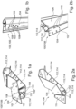
- FIGS 1A and 1B show schematically an exemplary component 100' of a carrosserie of a vehicle (not shown) comprising conventional draining means 102' in different perspective views.
- Figures 2A and 2B show schematically an exemplary component 100 of a carrosserie of a vehicle (not shown) comprising draining means 102 according to the present disclosure.
- Draining means 102, 102' are used to drain liquids and/or air from surfaces 104 and/or cavities of the component 100, 100' during the manufacturing process of the component 100, 100' and/or the carrosserie of the vehicle.
- the liquids may comprise paint, degrease liquid, water, de-ionized water, activation and/or passivation liquids etc.
- the component 100, 100' may comprise a main body 106, and the draining means 102, 102' may be formed on the surfaces 104 of the main body 106.
- the component 100' as exemplarily shown in Figures 1A and 1B is a casted part comprising several hollow profile sections 112, wherein the draining means 102' are arranged in one of the several hollow profile sections 112.
- the draining means 102' as exemplarily shown in Figures 1A and 1B are formed as substantially round holes 108, which are usually made by punching.
- the conventional round holes 108 may have a diameter from around 6 mm and up to around 20 mm, and therefore require the application of a tape (not shown) or the insertion of a plug (not shown) to be closed, which need to be applied or inserted manually, e.g., by a line worker.
- the draining means 102' has to be closed from inside the hollow profile section 112, so that the closed draining means 102' are not visible from an outer surface 110 of the component 100'.
- a cavity 114 being formed by the hollow profile section 112 is hard to reach and may be designed larger only to enable a manual application of a tape and/or a manual insertion of a plug. Therefore, the cavity 114 of the hollow profile section 112 may also be referred to as hard-to-reach area.
- draining means 102' which are arranged in hard-to-reach areas not being manually accessible, may be left open, which increases the risk of corrosion, because dirt may enter into the cavity 114 through the draining means 102' being left open.
- the component 100 as exemplarily shown in Figures 2A and 2B is also a casted part comprising several hollow profile sections 112, wherein the draining means 102 are arranged in one of the several hollow profile sections 112.
- the draining means 102 as exemplarily shown in Figures 2A and 2B are formed as slots 116, which may be made by sawing and/or lasercutting and/or milling. The manufacture method may depend on the type of metal the component 100 is formed of, e.g., aluminum, steel, aluminum alloy, steel alloy etc.
- the slots 116 have a length L larger than a width W, wherein the width W may be up to about 6 mm, and the length L may be up to about 100 mm.
- the width W of the slots 116 is crucial, whereas the length L of the slots is negligible at least with regard to sealing the slots 116.
- the width W of the slots 116 is restrictive for sealing or closing the slots via a sprayable sealing material, whereas the length L of the slots 116 may substantially be chosen as desired.
- the width W and the length L may be chosen such that a cross-sectional area of the slot substantially corresponds to a cross-sectional area of a conventional round hole 104.
- the cavity 114 being formed by the hollow profile section 112 is hard to reach.
- the sprayable sealing material 118 may be easily applicable to the slots 116 from inside the cavity, e.g., via an extension tube, a tiny robotic arm etc., and therefore, the cavity 114 can be designed small and/or compact.
- the cavity 114 can be designed according to the required strength, stability and the like, of the component. Further, in case some slots 116 may be left open, the risk of corrosion, for example due to the entry of dirt, is reduced compared to the conventional round holes 108, because the relatively narrow width of the slot 116 may prevent the entry of a larger amount of dirt. In other words, it is less likely that dirt may enter through an opening having a long but narrow cross-sectional area than through an opening having a substantially round cross-sectional area, wherein both cross-sectional areas are approximately the same size.
- Figures 3A and 3B show schematically the same exemplary component 100, wherein Figure 3A shows the component 100 before a sprayable sealing material 118 is applied, and Figure 3B shows the component 100 after the application of the sprayable sealing material 118.
- the exemplary component 100 comprises nine slots 116 being arrange in three groups 120 of each three slots 116.
- the sprayable sealing material 118 is applied in a first thickness (shown as areas having a small rhomb pattern) to seal the slots 116.
- the sprayable material 118 is applied in a second thickness (shown as areas having a large rhomb pattern), wherein the second thickness is smaller than the fist thickness.
- the sealing material 118 of the second thickness is applied to substantially plane surface section without any openings. In such areas, the sealing material 118 is used for damping to reduce noise. Therefore, the sealing material 118 may also be referred to as damping material.
- the sealing material 118 may be a sprayable material whose main purpose is the sealing or closing of the draining means 102, or the sealing material 118 may be a sprayable material whose main purpose is the damping of surfaces 104, 110, which additionally is able to seal the slots 116 being formed in the surfaces 104, 110 to be damped.
- the sealing material 118 may be a thermoplastic, e.g., waterborne acrylates, such as NUXODOL 3100 and EFDAMP AX-528 etc., and/or polyvinyl chloride (PVC), such as BETAGUARD INS 35 S, BETAGUARD DC 431-V, BETAGUARD EP 2009, BETAFILL 10101 etc.
- Figure 4 shows schematically and exemplarily a partial view of a component 100 according to the present disclosure.
- three dashed circles 122 mark welding spots, e.g., for spotweld, which are arranged close to the slot 116. Further, the slot 116 is arranged close to or at a transitional edge 124 of the component 100.
- Such compact arrangement of welding spots and draining means 102 allows reducing a size of the surface 104, on which the welding spots are arranged compared to a required size of the surface with draining means 102' being formed as round holes 108, since the punching method for forming the round holes requires a predetermined distance to edges of the main body 106 of the component 100, 100', such as the transitional edge 124, as well as to welding spots 122, which increases the required size of the respective surface.
- Figure 5 shows a schematic flow diagram of an exemplary method 200 for manufacturing the component 100 according to the present disclosure.
- the main body 106 of the component 100 is formed of a metal, particularly aluminum or steel.
- the main body 106 may be formed by casting, extruding etc., and/or comprising at least one of a bending portion, a welding portion, connecting portion, such as a welding connection, a riveting connection, a screwed connection, a glued connection, a brazed connection etc., and a beading/corrugation.
- the draining means 102 are getting formed into the main body 106 by cutting the at least one slot 116 in a surface 104, 110 of the component 100, either via a circular saw or via a laser.
- the slot 116 may be formed by milling.
- a step S3 the main body 106 is treated with at least one liquid, such as paint etc., is applied to the main body 106 of the component 106, e.g., via immersing the component 100 at least partly in the liquid.
- the excessive liquid is drained via the draining means 102 being formed as at least one slot 116 in at least one surface 104, 110 of the main body 106, from the main body 106 of the component 100.
- a layer of a first predetermined thickness of the sealing material 118 is spayed at least onto the draining means 102 (being formed as at least on slot 116), thereby sealing or closing the draining means 102.
- a computer program may be stored/distributed on a suitable medium such as an optical storage medium or a solid-state medium supplied together with or as part of other hardware, but may also be distributed in other forms, such as via the Internet or other wired or wireless telecommunication systems. Any reference signs in the claims should not be construed as limiting the scope of the claims.
Landscapes
- Engineering & Computer Science (AREA)
- Chemical & Material Sciences (AREA)
- Combustion & Propulsion (AREA)
- Transportation (AREA)
- Mechanical Engineering (AREA)
- Body Structure For Vehicles (AREA)
Priority Applications (1)
| Application Number | Priority Date | Filing Date | Title |
|---|---|---|---|
| EP22210576.9A EP4378801A1 (de) | 2022-11-30 | 2022-11-30 | Entwässerungsmittel für einen bestandteil eines fahrzeugwagens, bestandteil eines fahrzeugwagens und verfahren zur herstellung eines bestandteils eines fahrzeugwagens |
Applications Claiming Priority (1)
| Application Number | Priority Date | Filing Date | Title |
|---|---|---|---|
| EP22210576.9A EP4378801A1 (de) | 2022-11-30 | 2022-11-30 | Entwässerungsmittel für einen bestandteil eines fahrzeugwagens, bestandteil eines fahrzeugwagens und verfahren zur herstellung eines bestandteils eines fahrzeugwagens |
Publications (1)
| Publication Number | Publication Date |
|---|---|
| EP4378801A1 true EP4378801A1 (de) | 2024-06-05 |
Family
ID=84367206
Family Applications (1)
| Application Number | Title | Priority Date | Filing Date |
|---|---|---|---|
| EP22210576.9A Pending EP4378801A1 (de) | 2022-11-30 | 2022-11-30 | Entwässerungsmittel für einen bestandteil eines fahrzeugwagens, bestandteil eines fahrzeugwagens und verfahren zur herstellung eines bestandteils eines fahrzeugwagens |
Country Status (1)
| Country | Link |
|---|---|
| EP (1) | EP4378801A1 (de) |
Citations (6)
| Publication number | Priority date | Publication date | Assignee | Title |
|---|---|---|---|---|
| AT403684B (de) * | 1993-09-07 | 1998-04-27 | Muth Hans | Verfahren zum einbringen von hohlraumschutz sowie autokarosserie mit hohlräumen |
| EP1293387A2 (de) * | 2001-09-13 | 2003-03-19 | Wilhelm Karmann GmbH | Karosserie und Verfahren sowie Vorrichtung zum Füllen einer Fuge bei einer Karosserie |
| JP2009208015A (ja) * | 2008-03-05 | 2009-09-17 | Honda Motor Co Ltd | 自動車車体の防錆処理方法 |
| US20110285171A1 (en) * | 2010-05-20 | 2011-11-24 | Ari Garo Caliskan | Sandwich panel |
| DE102011011388A1 (de) * | 2011-02-17 | 2011-12-01 | Daimler Ag | Korrosionsgeschützter Kraftfahrzeughohlkörper und Herstellungsverfahren |
| DE102014018399A1 (de) * | 2014-12-11 | 2015-06-18 | Daimler Ag | Gussbauteil für eine Fahrzeugkarosserie |
-
2022
- 2022-11-30 EP EP22210576.9A patent/EP4378801A1/de active Pending
Patent Citations (6)
| Publication number | Priority date | Publication date | Assignee | Title |
|---|---|---|---|---|
| AT403684B (de) * | 1993-09-07 | 1998-04-27 | Muth Hans | Verfahren zum einbringen von hohlraumschutz sowie autokarosserie mit hohlräumen |
| EP1293387A2 (de) * | 2001-09-13 | 2003-03-19 | Wilhelm Karmann GmbH | Karosserie und Verfahren sowie Vorrichtung zum Füllen einer Fuge bei einer Karosserie |
| JP2009208015A (ja) * | 2008-03-05 | 2009-09-17 | Honda Motor Co Ltd | 自動車車体の防錆処理方法 |
| US20110285171A1 (en) * | 2010-05-20 | 2011-11-24 | Ari Garo Caliskan | Sandwich panel |
| DE102011011388A1 (de) * | 2011-02-17 | 2011-12-01 | Daimler Ag | Korrosionsgeschützter Kraftfahrzeughohlkörper und Herstellungsverfahren |
| DE102014018399A1 (de) * | 2014-12-11 | 2015-06-18 | Daimler Ag | Gussbauteil für eine Fahrzeugkarosserie |
Similar Documents
| Publication | Publication Date | Title |
|---|---|---|
| EP1362769A1 (de) | Expandierbare konische Verschlussstopfen | |
| US20100159273A1 (en) | Method and Apparatus for Forming a Layered Metal Structure with an Anodized Surface | |
| EP4378801A1 (de) | Entwässerungsmittel für einen bestandteil eines fahrzeugwagens, bestandteil eines fahrzeugwagens und verfahren zur herstellung eines bestandteils eines fahrzeugwagens | |
| CN109747397B (zh) | 车辆门及车辆门的制造方法 | |
| US10996544B2 (en) | Motor vehicle camera housing assembly and method for making it | |
| JP2019027593A5 (de) | ||
| US8052355B2 (en) | Cutting tool and processing method by the same | |
| US11945046B2 (en) | Laser edge welding of copper substrates | |
| US11904571B2 (en) | Composite material structure and processing method thereof | |
| EP3190462A1 (de) | Pellikel | |
| US5126005A (en) | Process for eliminating pits during chemical milling | |
| US4362595A (en) | Screen fabrication by hand chemical blanking | |
| JP4787596B2 (ja) | ガスケットの製造方法、及びシール構造 | |
| CN111197175A (zh) | 一种制造模压制品的方法及使用该方法的散热器格栅 | |
| JPH11170927A (ja) | 車両のルーフドリップ溝シール構造およびシール方法 | |
| CN113458727A (zh) | 控制铝框煨弯焊接变形的工艺方法及煨弯成型铝框 | |
| CN224208281U (zh) | 一种改善三防漆污染装机构 | |
| JPH0350323A (ja) | 2サイクルエンジン用スリーブ | |
| CN113829003B (zh) | 机壳的制作方法 | |
| CN114641718A (zh) | 透镜垫片、包括透镜垫片的透镜模块及透镜垫片制造方法 | |
| JP2009241384A (ja) | Alc片の製造方法、alc片、alc壁面の製造方法、alc壁面 | |
| JP6569469B2 (ja) | 排水用レール部材 | |
| KR102239209B1 (ko) | 도금방법 및 도금체 | |
| JP6905394B2 (ja) | ヘミング構造 | |
| JP6625261B2 (ja) | エレベータパネル及びエレベータパネルの製造方法 |
Legal Events
| Date | Code | Title | Description |
|---|---|---|---|
| PUAI | Public reference made under article 153(3) epc to a published international application that has entered the european phase |
Free format text: ORIGINAL CODE: 0009012 |
|
| STAA | Information on the status of an ep patent application or granted ep patent |
Free format text: STATUS: REQUEST FOR EXAMINATION WAS MADE |
|
| 17P | Request for examination filed |
Effective date: 20230904 |
|
| AK | Designated contracting states |
Kind code of ref document: A1 Designated state(s): AL AT BE BG CH CY CZ DE DK EE ES FI FR GB GR HR HU IE IS IT LI LT LU LV MC ME MK MT NL NO PL PT RO RS SE SI SK SM TR |
|
| STAA | Information on the status of an ep patent application or granted ep patent |
Free format text: STATUS: EXAMINATION IS IN PROGRESS |
|
| 17Q | First examination report despatched |
Effective date: 20250502 |