EP4378916A2 - Verfahren zum karbonisieren einer betonmischung und eine vorrichtung zur zugabe von kohlendioxid - Google Patents
Verfahren zum karbonisieren einer betonmischung und eine vorrichtung zur zugabe von kohlendioxid Download PDFInfo
- Publication number
- EP4378916A2 EP4378916A2 EP24156817.9A EP24156817A EP4378916A2 EP 4378916 A2 EP4378916 A2 EP 4378916A2 EP 24156817 A EP24156817 A EP 24156817A EP 4378916 A2 EP4378916 A2 EP 4378916A2
- Authority
- EP
- European Patent Office
- Prior art keywords
- mix
- carbon dioxide
- cement
- concrete
- mixer
- Prior art date
- Legal status (The legal status is an assumption and is not a legal conclusion. Google has not performed a legal analysis and makes no representation as to the accuracy of the status listed.)
- Pending
Links
Images






























































Classifications
-
- B—PERFORMING OPERATIONS; TRANSPORTING
- B28—WORKING CEMENT, CLAY, OR STONE
- B28C—PREPARING CLAY; PRODUCING MIXTURES CONTAINING CLAY OR CEMENTITIOUS MATERIAL, e.g. PLASTER
- B28C7/00—Controlling the operation of apparatus for producing mixtures of clay or cement with other substances; Supplying or proportioning the ingredients for mixing clay or cement with other substances; Discharging the mixture
- B28C7/02—Controlling the operation of the mixing
- B28C7/022—Controlling the operation of the mixing by measuring the consistency or composition of the mixture, e.g. with supply of a missing component
- B28C7/024—Controlling the operation of the mixing by measuring the consistency or composition of the mixture, e.g. with supply of a missing component by measuring properties of the mixture, e.g. moisture, electrical resistivity, density
-
- B—PERFORMING OPERATIONS; TRANSPORTING
- B28—WORKING CEMENT, CLAY, OR STONE
- B28C—PREPARING CLAY; PRODUCING MIXTURES CONTAINING CLAY OR CEMENTITIOUS MATERIAL, e.g. PLASTER
- B28C5/00—Apparatus or methods for producing mixtures of cement with other substances, e.g. slurries, mortars, porous or fibrous compositions
- B28C5/42—Apparatus specially adapted for being mounted on vehicles with provision for mixing during transport
- B28C5/4203—Details; Accessories
-
- B—PERFORMING OPERATIONS; TRANSPORTING
- B28—WORKING CEMENT, CLAY, OR STONE
- B28C—PREPARING CLAY; PRODUCING MIXTURES CONTAINING CLAY OR CEMENTITIOUS MATERIAL, e.g. PLASTER
- B28C5/00—Apparatus or methods for producing mixtures of cement with other substances, e.g. slurries, mortars, porous or fibrous compositions
- B28C5/46—Arrangements for applying super- or sub-atmospheric pressure during mixing; Arrangements for cooling or heating during mixing, e.g. by introducing vapour
- B28C5/462—Mixing at sub- or super-atmospheric pressure
-
- B—PERFORMING OPERATIONS; TRANSPORTING
- B28—WORKING CEMENT, CLAY, OR STONE
- B28C—PREPARING CLAY; PRODUCING MIXTURES CONTAINING CLAY OR CEMENTITIOUS MATERIAL, e.g. PLASTER
- B28C7/00—Controlling the operation of apparatus for producing mixtures of clay or cement with other substances; Supplying or proportioning the ingredients for mixing clay or cement with other substances; Discharging the mixture
- B28C7/04—Supplying or proportioning the ingredients
-
- C—CHEMISTRY; METALLURGY
- C04—CEMENTS; CONCRETE; ARTIFICIAL STONE; CERAMICS; REFRACTORIES
- C04B—LIME, MAGNESIA; SLAG; CEMENTS; COMPOSITIONS THEREOF, e.g. MORTARS, CONCRETE OR LIKE BUILDING MATERIALS; ARTIFICIAL STONE; CERAMICS; REFRACTORIES; TREATMENT OF NATURAL STONE
- C04B28/00—Compositions of mortars, concrete or artificial stone, containing inorganic binders or the reaction product of an inorganic and an organic binder, e.g. polycarboxylate cements
- C04B28/02—Compositions of mortars, concrete or artificial stone, containing inorganic binders or the reaction product of an inorganic and an organic binder, e.g. polycarboxylate cements containing hydraulic cements other than calcium sulfates
- C04B28/04—Portland cements
-
- C—CHEMISTRY; METALLURGY
- C04—CEMENTS; CONCRETE; ARTIFICIAL STONE; CERAMICS; REFRACTORIES
- C04B—LIME, MAGNESIA; SLAG; CEMENTS; COMPOSITIONS THEREOF, e.g. MORTARS, CONCRETE OR LIKE BUILDING MATERIALS; ARTIFICIAL STONE; CERAMICS; REFRACTORIES; TREATMENT OF NATURAL STONE
- C04B28/00—Compositions of mortars, concrete or artificial stone, containing inorganic binders or the reaction product of an inorganic and an organic binder, e.g. polycarboxylate cements
- C04B28/02—Compositions of mortars, concrete or artificial stone, containing inorganic binders or the reaction product of an inorganic and an organic binder, e.g. polycarboxylate cements containing hydraulic cements other than calcium sulfates
- C04B28/08—Slag cements
-
- C—CHEMISTRY; METALLURGY
- C04—CEMENTS; CONCRETE; ARTIFICIAL STONE; CERAMICS; REFRACTORIES
- C04B—LIME, MAGNESIA; SLAG; CEMENTS; COMPOSITIONS THEREOF, e.g. MORTARS, CONCRETE OR LIKE BUILDING MATERIALS; ARTIFICIAL STONE; CERAMICS; REFRACTORIES; TREATMENT OF NATURAL STONE
- C04B40/00—Processes, in general, for influencing or modifying the properties of mortars, concrete or artificial stone compositions, e.g. their setting or hardening ability
- C04B40/0091—Processes of mixing characterised by carbon dioxide treatment
-
- C—CHEMISTRY; METALLURGY
- C04—CEMENTS; CONCRETE; ARTIFICIAL STONE; CERAMICS; REFRACTORIES
- C04B—LIME, MAGNESIA; SLAG; CEMENTS; COMPOSITIONS THEREOF, e.g. MORTARS, CONCRETE OR LIKE BUILDING MATERIALS; ARTIFICIAL STONE; CERAMICS; REFRACTORIES; TREATMENT OF NATURAL STONE
- C04B2111/00—Mortars, concrete or artificial stone or mixtures to prepare them, characterised by specific function, property or use
- C04B2111/00017—Aspects relating to the protection of the environment
- C04B2111/00019—Carbon dioxide sequestration
-
- Y—GENERAL TAGGING OF NEW TECHNOLOGICAL DEVELOPMENTS; GENERAL TAGGING OF CROSS-SECTIONAL TECHNOLOGIES SPANNING OVER SEVERAL SECTIONS OF THE IPC; TECHNICAL SUBJECTS COVERED BY FORMER USPC CROSS-REFERENCE ART COLLECTIONS [XRACs] AND DIGESTS
- Y02—TECHNOLOGIES OR APPLICATIONS FOR MITIGATION OR ADAPTATION AGAINST CLIMATE CHANGE
- Y02P—CLIMATE CHANGE MITIGATION TECHNOLOGIES IN THE PRODUCTION OR PROCESSING OF GOODS
- Y02P40/00—Technologies relating to the processing of minerals
- Y02P40/10—Production of cement, e.g. improving or optimising the production methods; Cement grinding
- Y02P40/18—Carbon capture and storage [CCS]
-
- Y—GENERAL TAGGING OF NEW TECHNOLOGICAL DEVELOPMENTS; GENERAL TAGGING OF CROSS-SECTIONAL TECHNOLOGIES SPANNING OVER SEVERAL SECTIONS OF THE IPC; TECHNICAL SUBJECTS COVERED BY FORMER USPC CROSS-REFERENCE ART COLLECTIONS [XRACs] AND DIGESTS
- Y02—TECHNOLOGIES OR APPLICATIONS FOR MITIGATION OR ADAPTATION AGAINST CLIMATE CHANGE
- Y02W—CLIMATE CHANGE MITIGATION TECHNOLOGIES RELATED TO WASTEWATER TREATMENT OR WASTE MANAGEMENT
- Y02W30/00—Technologies for solid waste management
- Y02W30/50—Reuse, recycling or recovery technologies
- Y02W30/91—Use of waste materials as fillers for mortars or concrete
Definitions
- cement mixes such as concrete mixes
- cement mixes are used in a multitude of compositions and procedures throughout the world.
- greenhouse gases such as carbon dioxide are a growing concern worldwide.
- the invention provides methods.
- the invention provides a method for carbonating a concrete mix comprising a type of cement that includes delivering dose of CO2 to the concrete mix while it is mixing in a mixer, where the delivery of the carbon dioxide commences within 3 minutes of the start of mixing of the concrete mix, and wherein the duration of the delivery of the carbon dioxide is 10 seconds to 4 minutes.
- the dose of carbon dioxide is 0.01-1.0% by weight cement (bwc).
- the delivery of the carbon dioxide commences within 1 minute of the start of mixing of the concrete mix.
- the mixer can be any suitable mixer, such as a stationary mixer or a transportable mixer; in certain embodiments, the mixer comprises a transportable mixer, e.g., a drum of a ready-mix truck.
- the dose of carbon dioxide is based on previous testing of a plurality of doses of carbon dioxide on a plurality of test mixes, wherein the test mixes comprise the type of cement in the concrete mix, for example at least three test doses of carbon dioxide can be used in the previous testing.
- the plurality of doses of carbon dioxide used in the previous testing are all 0.01-1.0% bwc
- the dose of carbon dioxide delivered to the mixing concrete is 0.01-1.0% bwc.
- the carbon dioxide can be delivered via a conduit to the surface of the mixing concrete, for example, a conduit positioned to be 5-200 cm from the surface of the mixing concrete, on average.
- the carbon dioxide is delivered as a mixture of solid and gaseous carbon dioxide.
- the invention provides a method for carbonating a concrete mix in a drum of a ready-mix truck comprising (i) positioning a first conduit for delivery of components of the concrete mix to the drum, wherein the first conduit contains a second conduit for delivery of carbon dioxide to the concrete mix, and wherein the components of the concrete mix comprise at least cement and water; (ii) delivering the components of the concrete mix to the drum via the first conduit to provide a concrete mix in the drum; (iii) mixing the concrete mix; and (iv) delivering a dose of carbon dioxide to the mixing concrete via an opening of the second conduit.
- the dose of carbon dioxide is 0.01-1.5% by weight cement.
- the carbon dioxide is a mixture of solid and gaseous carbon dioxide.
- the dose of carbon dioxide is based on previous testing of a plurality of doses of carbon dioxide on a plurality of test mixes, wherein the test mixes comprise the type of cement in the concrete mix. In certain embodiments, at least three test doses of carbon dioxide are used in the previous testing. In certain embodiments, the plurality of doses of carbon dioxide used in the previous testing are all 0.01-1.0% bwc, and the dose of carbon dioxide delivered to the mixing concrete is 0.01-1.0% bwc. In certain embodiments, the opening of the second conduit is positioned to be 5 cm to 200 cm, on average, from a surface of the mixing concrete.
- the invention provides apparatus.
- the invention provides an apparatus for delivering carbon dioxide to a drum of a ready-mix truck comprising (i) a first conduit configured for delivery of components of concrete to the drum of the ready-mix truck; and (ii) a second conduit contained within or attached to the first conduit configured for delivery of carbon dioxide to the drum of the ready-mix truck.
- the second conduit is made of material that is sufficiently flexible to move with the first conduit.
- the second conduit contains a third conduit, wherein the third conduit is configured to be extended from the second conduit when the first conduit is positioned to deliver the components of the concrete to the drum, and to be retracted when the first conduit is moved from the drum of the ready-mix truck
- Carbon dioxide emissions are recognized as a significant issue relating to cement production and the use of concrete as a building material. It is estimated that 5% of the world's annual CO 2 emissions are attributable to cement production. The industry has previously recognized a number of approaches to reduce the emissions intensity of the cement produced and used. The most significant improvements in efficiency and cement substitution are likely to be already known and available. Future emissions improvements will likely be incremental.
- innovative approaches are sought that can be a part of a portfolio strategy. Thus, a range of further approaches will also have to be pursued.
- the carbonation reactions are exothermic.
- the reaction proceeds in the aqueous state when Ca 2+ ions from the cementitious phases meet CO 3 2- ions from the applied gas.
- the carbonation heats of reaction for the main calcium silicate phases are 347 kJ/mol for C3 S and 184 kJ/mol for ⁇ -C2S and 74 kJ/mol for Ca(OH) 2 .
- C-S-H calcium silicate hydrate
- the reaction of carbon dioxide with a mature concrete microstructure is conventionally acknowledged to be a durability issue due to such effects as shrinkage, reduced pore solution pH, and carbonation induced corrosion.
- a carbonation reaction integrated into concrete production reacts CO 2 with freshly hydrating cement, rather than the hydration phases present in mature concrete, and does not have the same effects. Rather, by virtue of adding gaseous CO 2 to freshly mixing concrete the carbonate reaction products are anticipated to form in situ, be of nanoscale and be homogenously distributed.
- cement binder e.g., a hydraulic cement or non-hydraulic cement.
- cement mix includes a mix of a cement binder, e.g., a hydraulic cement, such as a Portland cement, and water; in some cases, “cement mix” includes a cement binder mixed with aggregate, such as a mortar (also termed a grout, depending on consistency), in which the aggregate is fine aggregate; or “concrete,” which includes a coarse aggregate.
- the cement binder may be a hydraulic or non-hydraulic cement, so long as it provides minerals, e.g.
- An exemplary hydraulic cement is Portland cement.
- the invention includes descriptions of hydraulic cement binder and hydraulic cement mixes, but it will be appreciated that any cement mix is envisioned, whether containing a hydraulic or non-hydraulic cement binder, so long as the cement binder is capable of forming stable or metastable products when exposed to carbon dioxide, e.g., contains calcium, magnesium, sodium, and/or potassium compounds such as CaO, MgO, Na 2 O, and/or K 2 O.
- the invention provides methods, apparatus, and compositions for production of a cement mix (concrete) containing cement, such as Portland cement, treated with carbon dioxide.
- a cement mix cement containing cement, such as Portland cement
- carbon dioxide refers to carbon dioxide in a gas, solid, liquid, or supercritical state where the carbon dioxide is at a concentration greater than its concentration in the atmosphere; it will be appreciated that under ordinary conditions in the production of cement mixes (concrete mixes) the mix is exposed to atmospheric air, which contains minor amounts of carbon dioxide.
- the present invention is directed to production of cement mixes that are exposed to carbon dioxide at a concentration above atmospheric concentrations.
- Cement mix operations are commonly performed to provide cement mixes (concrete) for use in a variety of applications, the most common of which is as a building material.
- Such operations include precast operations, in which a concrete structure is formed in a mold from the cement mix and undergoes some degree of hardening before transport and use at a location separate from the mix location, and ready mix operations, in which the concrete ingredients are supplied at one location and generally mixed in a transportable mixer, such as the drum of a ready mix truck, and transported to a second location, where the wet mix is used, typically by being poured or pumped into a temporary mold.
- Precast operations can be either a dry cast operation or a wet cast operation, whereas ready mix operations are wet cast. Any other operation in which a concrete mix is produced in a mixer and exposed to carbon dioxide during mixing is also subject to the methods and compositions of the invention.
- the carbon dioxide when the cement mix (concrete) is exposed to carbon dioxide, the carbon dioxide first dissolves in mix water and then forms intermediate species, before precipitating as a stable or metastable species, e.g., calcium carbonate. As the carbonate species are removed from solution, further carbon dioxide may dissolve in the water. In certain embodiments, the mix water contains carbon dioxide before exposure to the cement binder. All of these processes are encompassed by the term "carbonation" of the cement mix, as that term is used herein.
- the invention provides methods for preparing a mix containing cement, by contacting a mixture of a cement binder, e.g., hydraulic cement and water, and, optionally, other components such as aggregate (a "cement mix", or “concrete,” e.g., a “hydraulic cement mix”) with carbon dioxide during some part of the mixing of the cement mix, e.g., hydraulic cement mix.
- a cement binder e.g., hydraulic cement and water
- other components such as aggregate (a "cement mix", or “concrete,” e.g., a “hydraulic cement mix") with carbon dioxide during some part of the mixing of the cement mix, e.g., hydraulic cement mix.
- a hydraulic cement is used.
- a hydraulic cement used may be any hydraulic cement capable of forming reaction products with carbon dioxide. The hydraulic cement most commonly used is based upon Portland cement. Portland cement is made primarily from limestone, certain clay minerals, and gypsum, in a high temperature process that drives off carbon dioxide and chemically combines the primary ingredients into new compounds. In certain embodiments, the hydraulic cement in the hydraulic cement mix is partially or completely composed of Portland cement.
- hydraulic cement mix includes a mix that contains at least a hydraulic cement and water. Additional components may be present, such as aggregates, admixtures, and the like.
- the hydraulic cement mix is a concrete mix, i.e., a mixture of hydraulic cement, such as Portland cement, water, and aggregate, optionally also including an admixture.
- the methods in certain embodiments are characterized by contacting carbon dioxide with wet cement binder, e.g., hydraulic cement, in a mixer at any stage of the mixing, such as during mixing of the cement with water, or during the mixing of wetted cement with other materials, or both.
- the cement may be any cement, e.g., hydraulic cement capable of producing reaction products with carbon dioxide.
- the cement includes or is substantially all Portland cement, as that term is understood in the art.
- the cement may be combined in the mixer with other materials, such as aggregates, to form a cement-aggregate mixture, such as mortar or concrete.
- the carbon dioxide may be added before, during, or after the addition of the other materials besides the cement and the water.
- the water itself may be carbonated, i.e., contain dissolved carbon dioxide.
- the contacting of the carbon dioxide with the cement mix may occur when part but not all of the water has been added, or when part but not all of the cement has been added, or both.
- a first aliquot of water is added to the cement or cement aggregate mixture, to produce a cement or cement-aggregate mixture that contains water in a certain water/cement (w/c) ratio or range of w/c ratios.
- one or more components of the cement mix e.g., hydraulic cement mix, such as aggregate, may be wet enough that is supplies sufficient water so that the mix may be contacted with carbon dioxide.
- carbon dioxide is introduced to the mixture, while the mixture is mixing in a mixer.
- the carbon dioxide may be of any purity and/or form suitable for contact with cement, e.g., hydraulic cement during mixing to form reaction products. As described, the carbon dioxide is at least above the concentration of atmospheric carbon dioxide.
- the carbon dioxide may be liquid, gaseous, solid, or supercritical, or any combination thereof.
- the carbon dioxide is gaseous when contacted with the cement, e.g., hydraulic cement, though it may be stored prior to contact in any convenient form, e.g., in liquid form.
- some or all of the carbon dioxide may be in liquid form and delivered to the cement or cement mix (concrete), e.g., in such a manner as to form a mixture of gaseous and solid carbon dioxide; the stream of liquid carbon dioxide can be adjusted by, e.g., flow rate and/or orifice selection so as to achieve a desired ratio of gaseous to solid carbon dioxide, such as ratio of approximately 1:1, or within a range of ratios.
- the carbon dioxide may also be solid when delivered to the concrete, i.e., as dry ice; this is useful when a controlled or sustained release of carbon dioxide is desired, for example, in a ready mix truck in transit to a mix site, or other wet mix operations, as the dry ice sublimates over time to deliver gaseous carbon dioxide to the mix; the size and shape of the dry ice added to the mix may be manipulated to ensure proper dose and time of delivery.
- the carbon dioxide is dissolved in water and delivered to the cement or cement mix (concrete).
- the carbon dioxide may also be of any suitable purity for contact with the cement or cement mix (concrete), e.g., hydraulic cement during mixing under the specified contact conditions to form reaction products.
- the carbon dioxide is more than 5, 10, 20, 30, 40, 50, 60, 70, 80, 90, 95, or 99% pure. In certain embodiments, the carbon dioxide is more than 95% pure. In certain embodiments, the carbon dioxide is more than 99% pure. In certain embodiments, the carbon dioxide is 20-100% pure, or 30-100% pure, or 40-100% pure, or 50-100% pure, or 60-100% pure, or 70-100% pure, or 80-100% pure, or 90-100% pure, or 95-100% pure, or 98-100% pure, or 99-100% pure. In certain embodiments, the carbon dioxide is 70-100% pure. In certain embodiment, the carbon dioxide is 90-100% pure. In certain embodiment, the carbon dioxide is 95-100% pure.
- the impurities in the carbon dioxide may be any impurities that do not substantially interfere with the reaction of the carbon dioxide with the wet cement mix, e.g., hydraulic cement mix. Commercial sources of carbon dioxide of suitable purity are well-known.
- the carbon dioxide e.g., carbon dioxide gas, liquid, or solid
- the carbon dioxide may be commercially supplied high purity carbon dioxide.
- the commercial carbon dioxide e.g., gas, liquid, or solid
- the commercial carbon dioxide may be sourced from a supplier that processes spent flue gasses or other waste carbon dioxide so that sequestering the carbon dioxide in the cement mix, e.g., hydraulic cement mix sequesters carbon dioxide that would otherwise be a greenhouse gas emission.
- a cement mix e.g., a concrete mix
- less cement can be used in the production of a concrete that is equal in strength.
- the amount of carbon dioxide absorbed is modest but if a consistent strength benefit can be realized then there is motivation to optimize the process and reduce the cement content.
- masonry producers generally do not have any internal or external motivation to produce product that has a strength 119% of the conventional product. Instead, an economic gain can be realized by using a mix design that contains less cement and achieves, through help of the carbonation process, 100% of the uncarbonated product strength.
- a reduced cement mix design would additionally have clear environmental benefits given that Portland cement clinker typically has embodied CO 2 on the order of 866 kg CO 2e /tonne of clinker. If 5% of the cement was removed from the block mix design (about 333 kg/m 3 ) then the emissions savings would be around 14 kg/m 3 concrete before including any net offset related to the CO 2 absorption.
- the invention provides a carbonated concrete composition comprising an amount of cement that is less than the amount of cement needed in an uncarbonated concrete composition of the same or substantially the same mix design, e.g., at least 1, 2, 3, 4, 5, 6, 7, 8, 9, 10, 12, 15, 17, 20, 25, 30, 40, or 50% less cement, but with a strength, e.g., compressive strength, that is within 20, 15, 10, 5, 3, 2, or 1% of the compressive strength of the uncarbonated concrete mix at a given time or times after mixing, such as 24 hours, 2 days, 7 days, 14 days, 21 days, 56 days, or 91 days, or a combination thereof.
- a strength e.g., compressive strength
- Such compositions realize a net savings in CO 2 emissions that includes the amount of carbon dioxide taken up by the composition, and the amount of carbon dioxide emission avoided because less cement is needed in the production of the composition.
- the net emission savings may be at least 1, 2, 3, 4, 5, 7, 10, 12, 15, 17, 20, 25, 30, 35, 40, 45, 50, 60, 70, 80, 90, 100, 125, or 150 kg CO 2 /m 3 of concrete for the carbonated compared to the uncarbonated concrete.
- the concrete may be in the form of a precast object, such as a block, pipe, brick, paver, or the like; the concrete may be in the form of a ready-mix concrete that is poured into molds at a job site.
- the carbonation of the concrete may produce nanocrystals of calcium carbonate as described elsewhere herein.
- Substantial cost savings can also be realized by decreasing the amount of cement for a given concrete mix without sacrificing strength.
- the carbon dioxide is contacted with the cement mix, e.g., hydraulic cement mix during mixing by any suitable route, such as over part or all of the surface of the mixing cement mix, e.g., hydraulic cement mix, under the surface of the cement mix, e.g., hydraulic cement mix, or any combination thereof.
- the cement mix e.g., hydraulic cement mix during mixing by any suitable route, such as over part or all of the surface of the mixing cement mix, e.g., hydraulic cement mix, under the surface of the cement mix, e.g., hydraulic cement mix, or any combination thereof.
- carbon dioxide is introduced into the second container prior to pre-mixed concrete being introduced into that container.
- the concrete may be contacted with carbon dioxide as it is being transferred from the first mix container to the second container.
- the carbon dioxide may be in any form as described herein, e.g., gas, solid, or a mix of gas and solid.
- the carbon dioxide is introduced into the second container as a solid, or a mixture of gas and solid; for example, the carbon dioxide may be supplied in a conduit as liquid carbon dioxide and on exiting an opening or orifice of the conduit, be converted to solid and gaseous carbon dioxide, as described elsewhere herein; the stream of gaseous and solid carbon dioxide may be directed to the second container before introduction of the concrete, and/or directed to the stream of concrete introduced into the second container.
- conditions of the introduction may be adjusted to achieve a high ratio of solid to gaseous carbon dioxide.
- carbon dioxide may be introduced into the second container as dry ice, as described elsewhere herein. The carbon dioxide in the second container is then contacted with the pre-mixed concrete as it is poured into the second container and as the second container continues to mix the concrete.
- carbon dioxide can be introduced into the drum of the ready-mix truck, e.g., as gaseous and solid carbon dioxide formed from liquid carbon dioxide, or as solid dry ice, or a combination thereof, prior to the concrete being poured from the mixer into the drum. Additionally or alternatively, carbon dioxide may be directed to the stream of concrete as it is being poured from the mixer to the drum.
- the stream of gas and solid may be directed to contact the stream of concrete being poured from the mixer, as well as entering the drum of the ready-mix truck.
- the stream of solid and gaseous carbon dioxide may be positioned in such a way as to introduce carbon dioxide into the stream of concrete entering the drum of the truck, and also to introduce carbon dioxide into the drum itself.
- Carbon dioxide, e.g., solid carbon dioxide or a mixture of solid and gaseous carbon dioxide may also be introduced into the drum of the truck prior to the pouring of the concrete into the drum. It will be appreciated that any combination of the above approaches may be used in order to contact the concrete in the drum of the truck with carbon dioxide. Such approaches are especially useful with low doses of carbon dioxide, such as doses no greater than 2%, or no greater than 1.5%, or no greater than 1% bwc, as described elsewhere herein.
- the carbon dioxide is contacted with the cement mix, e.g., hydraulic cement mix during mixing by contact with the surface of the mixing cement mix, e.g., hydraulic cement mix.
- the cement mix e.g., hydraulic cement mix during mixing by contact with the surface of the mixing cement mix, e.g., hydraulic cement mix.
- the carbon dioxide contacted with the surface of the cement mix e.g., hydraulic cement mix dissolves and/or reacts in the water, and is then subsumed beneath the surface by the mixing process, which then exposes different cement mix, e.g., cement mix, to be contacted, and that this process continues for as long as the wetted hydraulic cement is exposed to the carbon dioxide.
- the process of dissolution and/or reaction may continue after the flow of carbon dioxide is halted, since carbon dioxide will likely remain in the gas mixture in contact with the cement mix, e.g., hydraulic cement mix.
- the solid carbon dioxide will sublimate and continue to deliver gaseous carbon dioxide to the cement mix, e.g., hydraulic cement mix after the flow of liquid carbon dioxide has ceased. This is particularly useful in ready mix truck operations, where there may be insufficient time at the batching facility to allow uptake of the desired amount of carbon dioxide; the use of liquid carbon dioxide which converts to gaseous and solid carbon dioxide allow more carbon dioxide to be delivered to the mix even after the truck leaves the batching facility.
- the concrete in a ready-mix operation, may be mixed in a stationary mixer, then transferred to the drum of the ready-mix truck, or the components of the concrete may be delivered to the drum of the ready-mix truck and the mixing of the components to provide concrete occurs in the drum.
- carbon dioxide may be delivered to the stationary mixer, and in such a case, the delivery may be similar or identical to that used in, e.g., a precast operation, i.e., carbon dioxide is delivered via a conduit which opens to the mixer and delivers the carbon dioxide to the surface of the mixing concrete.
- the carbon dioxide may be any form as described herein; in certain embodiments, the carbon dioxide is delivered as liquid which, upon exiting the opening of the conduit, converts to a solid and a gas, as described herein. Further carbonation of the concrete may be achieved, if desired, by delivery of additional carbon dioxide to the drum of the ready mix truck after the concrete is delivered to it. Alternatively, all carbon dioxide may be delivered to the drum of the ready-mix truck; this will clearly be the case if the mixing of the concrete occurs in the drum. In this case, a delivery system for carbon dioxide to the drum of the ready-mix truck is needed.
- the carbon dioxide can be delivered after the components of the concrete mix are placed in the drum; for example, in some ready-mix operations, the truck is moved to a wash rack where it is washed down prior to leaving the yard.
- the positioning of the conduit for the carbon dioxide also referred to as a wand or lance herein, so that the opening is in a certain position and attitude relative to the drum can be important; one aspect of some embodiments of the invention is positioning the wand, and/or apparatus for doing so, to facilitate efficient mixing of the gaseous and solid carbon dioxide with the cement mix as the drum rotates.
- Any suitable positioning method and/or apparatus may be used to optimize the efficiency of uptake of carbon dioxide into the mixing cement as long as it positions the wand in a manner that provides efficient uptake of the carbon dioxide, for example, by positioning the wand so that the opening is directed to a point where a wave of concrete created by fins of the ready mix drum folds over onto the mix; without being bound by theory it is thought that the wave folding over the fin immediately subsumes the solid carbon dioxide within the cement mix so that it releases gaseous carbon dioxide by sublimation into the mix rather than into the air, as it would do if on the surface of the mix.
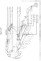
- One exemplary positioning is shown in Figure 134 , where the wand is aimed at the second fin in the drum of the truck, on the bottom side of the fin.
- the opening of the wand may be very close to the surface of the mixing concrete, as described below, to facilitate the directional flow of the carbon dioxide mix into the proper area.
- Part or all of the wand may be made of flexible material so that if a fin or other part of the drum hits the wand it flexes then returns to its original position.
- the invention provides a system for positioning a carbon dioxide delivery conduit on a ready mix truck so that the opening of the conduit is directed to a certain position in the drum of the truck, for example, as described above.
- the conduit may deliver gaseous carbon dioxide or a mixture of gaseous and solid carbon dioxide through the opening.
- the conduit is constructed of materials that can withstand the liquid carbon dioxide carried by the conduit to the opening.
- the system can include a guide, which may be mounted on the truck, for example permanently mounted, or that may be part of the lance assembly, that is configured to allow the reversible positioning of the conduit, for example, by providing a cylinder or holster into which the conduit can be inserted, so that the conduit is positioned at the desired angle for delivery of the carbon dioxide to a particular point, and a stop to ensure that the conduit is inserted so that the opening is at the desired distance from the concrete.
- a guide which may be mounted on the truck, for example permanently mounted, or that may be part of the lance assembly, that is configured to allow the reversible positioning of the conduit, for example, by providing a cylinder or holster into which the conduit can be inserted, so that the conduit is positioned at the desired angle for delivery of the carbon dioxide to a particular point, and a stop to ensure that the conduit is inserted so that the opening is at the desired distance from the concrete.
- the wand is positioned in the guide, for example, manually by the driver, or automatically by an automated system that senses the positions of the various components.
- a sensor may be tripped when the wand is positioned properly and a system controller may then begin carbon dioxide delivery, either at that time or after a desired delay.
- the controller can be configured so that if the conduit is not positioned properly, e.g., the sensor does not send the signal, the delivery will not start.
- the system may also be configured so that if one or more events occur during before, during, or after delivery, an alarm sounds and/or delivery is modulated, for example, stopped, or not initiated.
- an alarm can sound if the wand loses signal from the positioning sensor during injection, the pressure is greater than 25 psi when both valves for delivery of gaseous and liquid carbon dioxide to the conduit is closed, e.g., when both are closed (which determines if a valve sticks open), or if the next truck in the queue has not been initiated in a certain amount of time.
- Exemplary logic for a controller can include:
- a system controller may be configured to receive input regarding the identity of each truck at the carbon dioxide delivery site and select the appropriate action, e.g., delivery/no delivery, timing, flow, and amount of carbon dioxide delivered, and the like.
- a dialog box can pop up when the system controller gets the signal from the customer PLC asking an operator to "Please input Identification Number" (e.g., a 1-10 digit number), alternatively, the truck identifier numbers can be in a predetermined order, e.g., sequential. To choose the option, there may be a selector switch on the maintenance screen. Feedback may also be provided to an operator, e.g., a batcher, showing relevant information for the batches run, such as Identification Number, Time Batched, Time Injected, Dose Required and Dose Injected, and the like.
- the units of the dose can be any suitable units, for example either lbs or kgs depending on the units selected.
- a "spreadsheet" can be provided that shows all batches from the current day (or makes the date selectable) so that the batcher can review it and scroll though, for example a printable spreadsheet.
- carbon dioxide is added to the drum of a ready-mix truck while the truck is positioned to receive the components of the concrete; this allows earlier contact of the carbon dioxide with the concrete mix and also allows all components-concrete and carbon dioxide-to be added at once, avoiding the necessity for the truck operator to perform an additional step to add the carbon dioxide.
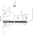
- a flexible large conduit generally referred to as a loading boot, such as a rubber boot, is positioned to direct materials (cement, aggregate, etc.) from loading hopper/bin into the concrete truck chute; this system minimizes spillage. See Figure 135 .
- a smaller conduit for delivery of carbon dioxide can be positioned within the larger conduit (boot) to move with the boot and be configured to direct the carbon dioxide into the drum of the ready-mix truck.
- a flexible hose housed in a pipe where the hose is extended through a loading boot and into a concrete truck's chute by the action of an apparatus suitable for extending the hose, such as a telescopic air cylinder rod or a rotary device.
- One or more components of the apparatus may be suitably configured to direct the carbon dioxide to a desired location or area in the drum, such as by a bend in the apparatus.
- carbon dioxide is directed as a solid/gas mixture into a mixer, such as into a ready-mix truck or into a stationary mixer
- it may be desirable to modulate the flow e.g., slow the flow, so that the solid carbon dioxide particles can clump together into larger particles before contacting the cement mix, e.g., hydraulic cement mix such as concrete, in the mixer.
- the cement mix e.g., hydraulic cement mix such as concrete
- One method modulating the flow of the solid/gas carbon dioxide mixture is to expand the diameter of the conduit through which the solid/gas mixture flows, and/or to introduce a bend into the conduit. Both the increase in diameter and the bend in the conduit serve to slow the velocity; however, in certain embodiments only an increase in diameter is used; in certain embodiments, only a bend is used. Any suitable step-up in size may be used, with or without a bend, so long as the rate of flow of the gas/solid carbon dioxide mix is slowed sufficiently to provide the desired clumping of solid particles before contact with the cement mix; in general it is preferred that the velocity remain high enough that the solid carbon dioxide does not stick inside the conduit.
- a larger diameter, with or without a bend, may also be used for a conduit used to deliver a gas/solid mixture of carbon dioxide to a non-stationary mixer, e.g., a ready-mix truck.
- the increase in diameter of the conduit may be any increase that produces the desired clumping of the solid carbon dioxide, preferably with no or very little buildup of solid carbon dioxide in the conduit.
- the flow of carbon dioxide may be directed from an opening or plurality of openings (e.g., manifold or conduit opening) that is at least 5, 10, 20, 30, 40, 50, 60, 70, 80, 90, or 100 cm from the surface of the cement mix, e.g., hydraulic cement mix during carbon dioxide flow, on average, given that the surface of the mix will move with mixing, and/or not more than 10, 20, 30, 40, 50, 60, 70, 80, 90, 100, 120, 140, 170, or 200 cm from the surface of the cement mix, e.g., hydraulic cement mix during carbon dioxide flow, on average.
- the opening is 5-100 cm from the surface, on average, such as 5-60 cm, for example 5-40 cm.
- dry ice may be used directly by addition to the concrete mix. This allows for controlled delivery as the dry ice sublimates, as described.
- dry ice may be added to a cement mix in a ready mix truck. The amount of dry ice added may be enough to provide a dose of 0.01-5% carbon dioxide bwc, for example, 0.01-1%, or 0.01-0.5%, or 0.01-0.2%, or 0.1-2% or 0.1-1%, or 0.2-3%, or 0.5-3%.
- the dry ice may be added in one or more batches.
- the shape of the dry ice may be selected depending on, e.g., the speed of gaseous carbon dioxide delivery desired; for example, if rapid delivery is desired, the dry ice may be added as small pellets, thus increasing surface/volume ratio for carbon dioxide sublimation, or if a slower delivery is desired, the dry ice may be added as a larger mass, e.g., slab, with a correspondingly smaller surface/volume ratio and slower sublimation, or any combination of shapes and masses to achieve the desired dose of carbon dioxide and rate of delivery.
- the dry ice may be added at any convenient stage in mixing, for example, at the start of mixing or within 5 or 10 minutes of the start of mixing, or later in the mixing, for example, as a ready mix truck approaches a job site or the time of delivery of its concrete load.
- solid carbon dioxide may be added before or after a first, second, or third addition of water where water addition to the concrete mix is divided into two or more doses.
- Mixing speed for the concrete mix may also be modulated to achieve a desired rate of dosing or other desired results.
- the invention provides a method for delivering carbon dioxide to concrete mixing in a ready mix truck by adding solid carbon dioxide to the concrete mix during the mixing, where at least 20, 30, 40, 50, 60, 70, 80, 90, 95, or 99% of the carbon dioxide delivered to the concrete is added in the form of solid carbon dioxide.
- any suitable route of providing the carbon dioxide may be used.
- the flow of carbon dioxide may be both under the surface and over the surface, either by use of two different openings or plurality of openings or by movement of the openings relative to the mix, e.g., under the surface at one stage and over the surface at another, which may be useful to prevent clogging of the openings.
- the carbon dioxide may be contacted with the cement mix, e.g., hydraulic cement mix such that it is present during mixing by any suitable system or apparatus.
- gaseous or liquid carbon dioxide is supplied via one or more conduits that contain one or more openings positioned to supply the carbon dioxide to the surface of the mixing cement mix, e.g., hydraulic cement mix.
- the conduit and opening may be as simple as a tube, e.g., a flexible tube with an open end.
- the conduit may be sufficiently flexible so as to allow for movement of various components of the cement mix, e.g., hydraulic cement mixing apparatus, the conduit opening, and the like, and/or sufficiently flexible to be added to an existing system as a retrofit.
- the conduit may be sufficiently rigid, or tied-off, or both, to insure that it does not interfere with any moving part of the cement mix, e.g., hydraulic cement mixing apparatus.
- part of the conduit can be used for supplying other ingredients to the cement mix, e.g., water, and configured such that either the other ingredient or carbon dioxide flows through the conduit, e.g., by a T-junction.
- the carbon dioxide exits the conduit or conduits via one or more manifolds comprising a plurality of openings.
- the opening or openings may be positioned to reduce or eliminate clogging of the opening with the cement mix, e.g., hydraulic cement mix.
- the manifold is generally connected via the conduit to at least one fluid (gas or liquid) supply valve, which governs flow of pressurized fluid between a carbon dioxide source, e.g. a pressurized gas or liquid supply, and the manifold.
- the fluid supply valve may include one or more gate valves that permit the incorporation of calibration equipment, e.g., one or more mass flow meters.
- the mass of carbon dioxide provided to the cement mix e.g., hydraulic cement mix via the conduit or conduits may be controlled by a mass flow controller, which can modulate the fluid supply valve, e.g., close the valve to cease supply of carbon dioxide fluid (liquid or gas).
- Carbon dioxide may also be delivered to the cement mix, e.g., hydraulic cement mix as part of the mix water, i.e., dissolved in some or all of the mix water.
- Methods of charging water with carbon dioxide are well-known, such as the use of technology available in the soda industry. Some or all of the carbon dioxide to be used may be delivered this way.
- the mix water may be charged to any desired concentration of carbon dioxide achievable with the available technology, such as at least 1, 2, 4, 6, 8, 10, 12, 14, or 16 g of carbon dioxide/L of water, and/or not more than 2, 4, 6, 8, 10, 12, 14, 18, 20, 22, or 24 g of carbon dioxide/L of water, for example 1-12, 2-12, 1-10, 2-10, 4-12, 4-10, 6-12, 6-10, 8-12, or 8-10 g of carbon dioxide/L of water. It will be appreciated that the amount of carbon dioxide dissolved in the mix water is a function of the pressure of the carbon dioxide and the temperature of the mix water; at lower temperatures, far more carbon dioxide can be dissolved than at higher temperatures.
- the mix water so charged contacts the cement mix, e.g., hydraulic cement mix and the carbon dioxide contained therein reacts very quickly with components of the cement mix, e.g., hydraulic cement mix, leaving the water available to dissolve additional carbon dioxide that may be added to the system, e.g., in gaseous form.
- cement mix e.g., hydraulic cement mix
- carbon dioxide contained therein reacts very quickly with components of the cement mix, e.g., hydraulic cement mix, leaving the water available to dissolve additional carbon dioxide that may be added to the system, e.g., in gaseous form.
- a cement mix such as a concrete mix is carbonated with carbon dioxide supplied as carbonated water, for example, in the drum of a ready mix truck.
- the carbonated water serves as a portion of the total mix water for the particular mix.
- the carbonated water can provide at least 1, 5, 10, 15, 20, 25, 30, 35, 40, 50, 60, 70, 80, or 90% of the total mix water, and/or no more than 10, 20, 30, 40, 50, 60, 70, 80, 90, 95, or 100% of the mix water.
- the carbonated water may be added at the start of mixing of the cement mix, or it may be added after the start of mixing, i.e., after a first addition of water to wet the cement mix.
- the carbonated water is less than 100% of the total mix water, for example, less than 80%, or less than 70%, or less than 60%, or less than 50%.
- non-carbonated water is first added to the mix, and the cement mix, e.g., concrete, is allowed to mix for a certain period before carbonated water is added, for example, for at least 5, 10, 15, 20, 30, 40, or 50 seconds, or at least 1, 2, 3, 4, 5, 6, 8, 10, 15, 20, 25, 30, 40, 50, or 60 minutes before addition of the carbonated water, and/or not more than 10, 15, 20, 30, 40, or 50 seconds, or 1, 2, 3, 4, 5, 6, 8, 10, 15, 20, 25, 30, 40, 50, 60, 90, 120, 240, or 360 minutes before addition of carbonated water.
- the cement mix e.g., concrete
- the delay before carbonated water is added to the mix is between 10 seconds and 5 minutes, for example, between 20 seconds and 40 minutes, such as between 30 seconds and 3 minutes. See Example 38.
- the flow rate of the carbonated water may be adjusted so that a certain duration is required for complete addition, such as a duration of at least 10, 20, 30, 40, or 50 seconds, or at least 1, 2, 3, 4, 5, 6, 7, 8, 9, 10, 12, 15, 20, or 30 minutes, and/or not more than 10, 20, 30, 40, or 50 seconds, or not more than 1, 2, 3, 4, 5, 6, 7, 8, 9, 10, 12, 15, 20, or 30 minutes.
- the duration of addition of carbonated water is between 30 seconds and 8 minutes, for example, between 30 seconds and 6 minutes, such as between 30 second and 4 minutes. See Example 38.
- the carbonated water may contribute all of the carbon dioxide used to carbonate a cement mix, e.g., concrete (neglecting atmospheric carbon dioxide); this is especially true for low-dose carbonation, for example, carbonation with a dose of carbon dioxide of less than 1.5% bwc, or less than 1.0% bwc, or less than 0.8% bwc.
- the carbonated water may contribute part or all of the carbon dioxide used to carbonate a cement mix, e.g., concrete, such as not more than 10, 20, 30, 40, 50, 60, 70, 80, 90, 95, or 100% of the carbon dioxide and/or at least 5, 10, 20, 30, 40, 50, 60, 70, 80, 90, or 95% of the carbon dioxide.
- the remaining carbon dioxide is supplied as a gas. In certain embodiments, the remaining carbon dioxide is supplied as a solid. In certain embodiments, the remaining carbon dioxide is supplied as a mixture of a gas and a solid, for example, carbon dioxide delivered to an orifice directed into the mixer in liquid form, which becomes gas and solid when passing through the orifice.
- the exact mix of carbonated water and other carbon dioxide source will be determined based on the dose of carbon dioxide to be delivered and other factors, such as delivery time, temperature (lower temperatures allow greater carbon dioxide delivery via carbonated water), and the like.
- the carbonated water may be produced by any suitable method, as described herein, and may be delivered to the mixer, e.g., the ready mix truck, via the normal water line or via a dedicated line.
- the carbonated water is produced from process water that is produced during, e.g., a ready mix operation, such as carbonated wash water that has been filtered, or unfiltered carbonated wash water, or a combination thereof.
- the wash water may be carbonated by any suitable method. See Example 39.
- the carbonated wash water can provide at least 1, 5, 10, 15, 20, 25, 30, 35, 40, 50, 60, 70, 80, or 90% of the total carbonated mix water, and/or no more than 10, 20, 30, 40, 50, 60, 70, 80, 90, 95, or 100% of the total carbonated mix water.
- carbonated water is delivered to the mix at the batch site and/or during transportation, and an optional dose is delivered at the job site, depending on the characteristics of the mix measured at the job site.
- the use of carbonated water can allow for very high efficiencies of carbon dioxide uptake, as well as precise control of dosage, so that highly efficient and reproducible carbon dioxide dosing can be achieved.
- the efficiency of carbonation can be greater than 60, 70, 80, 90, or even 95%, even when operating in mixers, such as ready mix drums, which are open to the atmosphere.
- the carbon dioxide is supplied from a source of carbon dioxide, such as, in the case of gaseous carbon dioxide, a pressurized tank filled with carbon dioxide-rich gas, and a pressure regulator.
- the tank may be re-filled when near empty, or kept filled by a compressor.
- the regulator may reduce the pressure in the tank to a maximum feed pressure.
- the maximum feed pressure may be above atmospheric, but below supercritical gas flow pressure.
- the feed pressure may be, for example, in a range from 120 to 875 kPa.
- a pressure relief valve may be added to protect the carbon dioxide source components.
- the carbon dioxide supplied by the carbon dioxide source may be about room temperature, or it may be chilled or heated as desired. In certain embodiments, some or all of the carbon dioxide is supplied as a liquid.
- the liquid is converted to gas before delivery to the mixer; in other cases, the remains a liquid in storage and movement to the mixer, and when released at the mixer forms a mixture comprising solid and gaseous carbon dioxide.
- one or more pressure sensors may be used ; e.g., for the nozzle system to control dry ice formation between the nozzle and solenoid as well as to confirm pre-solenoid pressure is maintained to ensure the line remains liquid.
- Carbon dioxide may be introduced to the mixer such that it contacts the hydraulic cement mix before, during, or after addition of water, or any combination thereof, so long as it is present during some portion of the mixing of some or all of the cement mix, e.g., hydraulic cement mix.
- the carbon dioxide is introduced during a certain stage or stages of mixing.
- the carbon dioxide is introduced to a cement mix, e.g., hydraulic cement mix during mixing at one stage only.
- the carbon dioxide is introduced during one stage of water addition, followed by a second stage of water addition.
- the carbon dioxide is introduced to one portion of cement mix, e.g., hydraulic cement mix, followed by addition of one or more additional portions of cement mix, e.g., hydraulic cement mix.
- the carbon dioxide is introduced into a first stage of mixing of water in the cement mix, e.g., hydraulic cement mix, then, after this stage, additional water is added without carbon dioxide.
- water may be added to a cement mix, e.g., hydraulic cement mix, e.g., a Portland cement mix, until a desired w/c ratio is achieved, then carbon dioxide may be contacted during mixing of the cement mix, e.g., hydraulic cement mix for a certain time at a certain flow rate or rates (or as directed by feedback, described further herein), then after carbon dioxide flow has stopped, additional water may be added in one or more additional stages to reach a desired w/c content, or a desired flowability, in the cement mix, e.g., hydraulic cement mix.
- the cement mixes contain aggregates, and it will be appreciated that the available aggregate may already have a certain water content and that little or no additional water need be added to achieve the desired w/c ratio for the first stage and that, in some environments, it may not be possible to achieve the desired w/c ratio because aggregate may be too wet, in which case the closest w/c ratio to the optimum is achieved.
- the w/c ratio for the first stage is less than 0.5, or less than 0.4, or less than 0.3, or less than 0.2, or less than 0.18, or less than 0.16, or less than 0.14, or less than 0.12, or less than 0.10, or less than 0.08, or less than 0.06.
- the w/c ratio for the first stage is less than 0.4. In certain embodiments, the w/c ratio for the first stage is less than 0.3. In certain embodiments, the w/c ratio for the first stage is less than 0.2. In certain embodiments, the w/c ratio for the first stage is less than 0.18. In certain embodiments, the w/c ratio for the first stage is less than 0.14. In certain embodiments, the w/c ratio for the first stage is 0.04-0.5, or 0.04-0.4, or 0.04-0.3, or 0.04-0.2, or 0.04-0.18, or 0.04-0.16, or 0.04-0.14, or 0.04-0.12, or 0.04-0.10, or 0.04-0.08.
- the w/c ratio for the first stage is 0.06-0.5, or 0.06-0.4, or 0.06-0.3, or 0.06-0.24, or 0.06-0.22, or 0.06-0.2, or 0.06-0.18, or 0.06-0.16, or 0.06-0.14, or 0.06-0.12, or 0.06-0.10, or 0.06-0.08.
- the w/c ratio for the first stage is 0.08-0.5, or 0.08-0.4, or 0.08-0.3, or 0.08-0.24, or 0.08-0.22, or 0.08-0.2, or 0.08-0.18, or 0.08-0.16, or 0.08-0.14, or 0.08-0.12, or 0.08-0.10.
- the w/c ratio for the first stage is 0.06-0.3. In certain embodiments, the w/c ratio for the first stage is 0.06-0.2. In certain embodiments, the w/c ratio for the first stage is 0.08-0.2.
- Addition of additional water in subsequent stages to the first stage, when, in general, no further carbon dioxide is introduced, may be done to achieve a certain final w/c ratio, or to achieve a certain flowability. For example, for a ready-mix truck, a certain amount of water is added to the mixture at the ready-mix production site, then further water may be added at the work site to achieve proper flowability at the work site. Flowability may be measured by any suitable method, for example, the well-known slump test.
- carbon dioxide is added during mixing to a portion of a cement mix, e.g., hydraulic cement mix in one stage, then additional portions of materials, e.g., further cement mix, e.g., hydraulic cement mix, are added in one or more additional stages.
- a cement mix e.g., hydraulic cement mix in one stage
- additional portions of materials e.g., further cement mix, e.g., hydraulic cement mix
- the carbon dioxide e.g., gaseous carbon dioxide or liquid carbon dioxide
- the mixing cement mix e.g., hydraulic cement mix, for example, in the first stage of mixing, at a certain flow rate and for a certain duration in order to achieve a total carbon dioxide exposure.
- the flow rate and duration will depend on, e.g., the purity of the carbon dioxide gas, the total batch size for the cement mix, e.g., hydraulic cement mix and the desired level of carbonation of the mix.
- a metering system and adjustable valve or valves in the one or more conduits may be used to monitor and adjust flow rates.
- the duration of carbon dioxide flow to provide exposure is at or below a maximum time, such as at or below 100, 50, 20, 15, 10, 8, 5, 4, 3, 2, or one minute. In certain embodiments, the duration of carbon dioxide flow is less than or equal to 5 minutes. In certain embodiments, the duration of carbon dioxide flow is less than or equal to 4 minutes. In certain embodiments, the duration of carbon dioxide flow is less than or equal to 3 minutes. In certain embodiments, the duration of carbon dioxide flow is less than or equal to 2 minutes. In certain embodiments, the duration of carbon dioxide flow is less than or equal to 1 minutes.
- the duration of carbon dioxide flow to provide exposure is within a range of times, such as 0.5-20 min, or 0.5-15 min, or 0.5-10 min, or 0.5-8 min, or 0.5-5 min, or 0.5-4 min, or 0.5-3 min, or 0.5-2 min, or 0.5-1 min, or 1-20 min, or 1-15 min, or 1-10 min, or 1-8 min, or 1-5 min, or 1-4 min, or 1-3 min, or 1-2 min.
- the duration of carbon dioxide flow is 0.5-5 min.
- the duration of carbon dioxide flow is 0.5-4 min.
- the duration of carbon dioxide flow is 0.5-3 min.
- the duration of carbon dioxide flow is 1-5 min.
- the duration of carbon dioxide flow is 1-4 min.
- the duration of carbon dioxide flow is 1-3 min.
- the duration of carbon dioxide flow is 1-2 min.
- the flow rate and duration of flow may be set or adjusted to achieve a desired level of carbonation, as measured by weight of cement (bwc). It will be appreciated that the precise level of carbonation will depend on the characteristics of a given mix and mix operation. In certain embodiments, the level of carbonation is more than 0.5, 1, 2, 3, 4, 5, 6, 7, 8, 9, or 10% bwc. In certain embodiments, the level of carbonation is more than 1% by weight. In certain embodiments, the level of carbonation is more than 2% bwc. In certain embodiments, the level of carbonation is more than 3% bwc. In certain embodiments, the level of carbonation is more than 4% bwc. In certain embodiments, the level of carbonation is more than 5% bwc.
- the level of carbonation is more than 6% bwc. In certain embodiments, the level of carbonation is 1-20%, or 1-15%, or 1-10%, or 1-8%, or 1-6%, or 1-5%, or 1-4%, or 1-3%, or 1-2%, or 2-20%, or 2-15%, or 2-10%, or 2-8%, or 2-6%, or 2-5%, or 2-4%, or 2-3%, or 0.5-20%, or 0.5-15%, or 0.5-10%, or 0.5-8%, or 0.5-6%, or 0.5-5%, or 0.5-4%, or 0.5-3%, or 0.5-2%. In certain embodiments, the level of carbonation is 0.5-3%. In certain embodiments, the level of carbonation is 0.5-2%.
- the level of carbonation is 1-6%. In certain embodiments, the level of carbonation is 1-4%. In certain embodiments, the level of carbonation is 2-8%. In certain embodiments, the level of carbonation is 2-6%. In certain embodiments, the level of carbonation is 2-4%. In certain embodiments, the level of carbonation is 3-10%. In certain embodiments, the level of carbonation is 3-8%. In certain embodiments, the level of carbonation is 3-6%. In certain embodiments, the level of carbonation is 4-10%. In certain embodiments, the level of carbonation is 4-8%. In certain embodiments, the level of carbonation is 4-6%. In certain embodiments, the level of carbonation is 5-10%. In certain embodiments, the level of carbonation is 5-8%.
- the level of carbonation is 5-6%.
- the level of carbonation may be ascertained by any suitable method, such as by the standard combustion analysis method, e.g. heating sample and quantifying the composition of the off gas.
- An instrument such as the Eltra CS-800 (KR Analytical, Cheshire, UK), or instrument from LECO (LECO Corporation, St. Joseph, Michigan) may be used.
- the level of carbonation also depends on the efficiency of carbonation, and that inevitably some of the carbon dioxide delivered to the mixing cement mix will be lost to the atmosphere; thus, the actual amount of carbon dioxide delivered can be adjusted based on the expected efficiency of carbonation.
- an appropriate factor may be added to determine the amount of carbon dioxide that is to be delivered as a dose to the cement mix; e.g., if the expected efficiency is 50% and the desired carbonation level is 1% bwc, then a dose of 2% bwc would be delivered to the mix.
- Appropriate doses may be calculated for desired carbonations at an efficiency of 5, 10, 20, 30, 40, 50, 60, 65, 70, 75, 80, 85, 90, 95, 96, 97, 98, or 99%.
- a relatively low level of carbonation is used, e.g., a level of carbonation below 1%, 0.8%, 0.7%, 0.6%, 0.5%, 0.4%, 0.3%, 0.2%, 0.1%, or 0.05% bwc. It has been found that certain properties, e.g., early strength development and set, may be accelerated in cement mixes, such as hydraulic cement mixes, that are exposed to relatively low levels of carbon dioxide during mixing. It is possible that, in some cases, the exposure may be low enough that the degree of carbonation is not measurably above that of a similar cement mix that has not been exposed to carbon dioxide; nonetheless, the exposure may lead to the desired enhanced properties.
- the mixing cement mix is exposed to a certain relatively low dose of carbon dioxide (in some cases regardless of final carbonation value); in this sense, carbon dioxide is used like an admixture whose final concentration in the cement mix is not important but rather its effects on the properties of the mix.
- the mix may be exposed to a dose of carbon dioxide of not more than 1.5%, 1.2%, 1%, 0.8%, 0.7%, 0.6%, 0.5%, 0.4%, 0.3%, 0.2%, 0.1%, or 0.05% bwc and/or at least 0.01, 0.05, 0.1, 0.2, 0.3, 0.4, 0.5, 0.6, 0.7, 0.8, 0.9, 1.0, or 1.2% bwc, such as a dose of 0.01-1.5%, 0.01-1.2%, 0.01-1%, 0.01-0.8%, 0.01-0.6%, 0.01-0.5%, 0.01-0.4%, 0.01-0.3%, 0.01-0.2%, or 0.01-0.1% bwc, or a dose of 0.02-1.5%, 0.02-1.2%, 0.02-1%, 0.02-0.8%, 0.02-0.6%, 0.02-0.5%, 0.02-0.4%, 0.02-0.3%, 0.02-0.2%, or 0.02-0.1% bwc, or a dose of 0.02-1.
- the choice of exposure level will depend on factors such as efficiency of carbonation in the process being used, degree of modulation of one or more properties desired (e.g., early strength development or early set), type of operation (e.g., dry cast vs. wet cast), and type of cement, as different types of cement may produce mixes with different degrees of modulation with a given carbon dioxide exposure. If an unfamiliar cement or mix type is being used, preliminary work may be done to find one or more suitable carbon dioxide doses to produce the desired results. Especially in the case of accelerated strength and/or set development, the use of an appropriate dose of carbon dioxide can allow work to progress faster, e.g., vertical pours may move upward more quickly, surfaces may be finished earlier, molds removed earlier, and the like.
- the dose chosen for a given mix as well as dosing conditions for example, to produce a desired increase in early strength or set, or to produce an optimal increase in early strength or set, can be dependent on the mix and especially on the cement used in the mix, as well as conditions in the field where dosing and use actually occur.
- Cements used in mixes are generally produced locally and vary from one geographic location to another, and the particular chemistry of a cement can determine whether or not it will benefit from carbonation, as well as optimal dosing parameters, such as overall dose, time to add carbon dioxide, rate of addition, and the like.
- Other components of a particular mix e.g. SCMs such as fly ash or slag, may also provide one or more reactive species that also influence carbonation. See, e.g., Example 45.
- the invention provides methods for determining whether or not to carbonate a given cement mix, and/or to determine a level of carbonation and/or dose of carbon dioxide and/or dosing conditions to achieve a desired result from carbonation of a cement mix, e.g., early strength development, or strength development in a particular time frame, reduced amount of cement required, or the like.
- the determination may be made by predictions for a given mix, e.g., based on the chemistry of the components, or testing, or a combination thereof. In testing, any suitable characteristic or combination of characteristics may be monitored in the testing, such as strength, flowability, and other characteristics that are important for the particular batch design being tested.
- the invention provides a method of carbonating a cement mix, e.g., concrete, during mixing, where carbon dioxide is added to the mix at a certain dose or range of doses, where the certain dose or range of doses is determined by testing one or more components of the mix, for example, the concrete, to determine a dose or a range of doses that produces optimal or desired increase in early strength and/or set.
- a cement mix e.g., concrete
- composition of the cement mix for testing can be any suitable composition, for example, as simple as cement and water, or a mortar also including fine aggregate, e.g., sand, as well as optional additional components, such as admixtures and the like. See Examples for compositions used in testing.
- the concrete mix to be used in a given operation is tested.
- Carbonation of the test cement mix can be achieved by any of the methods described herein, for example by delivery of carbon dioxide to the cement mix under controlled conditions to achieve a certain dose of carbon dioxide to the mix.
- the carbonation is achieved by using a bicarbonate solution, rather than carbon dioxide. It is thought that essentially all of the bicarbonate delivered to a concrete mix will be converted to carbonate so it is possible to control the exact level of carbonation of the mix achieved, and thus to first determine a desired level of carbonation, e.g., by testing a plurality of levels of carbonation to find the level or range of levels that produces the desired effect or effects. See, e.g., Example 37.
- a dose or range of doses in general a plurality of tests is conducted, i.e., using at least two, or at least three, or at least four different doses of carbon dioxide.
- the doses may all be below 1.5%, or 1.2%, or 1.0%, or 0.8%, or 0.6% carbon dioxide bwc.
- a dose or range of doses to be used in the field is determined from one or more test results from the test mixes, for example, calorimetry results, as described herein, and/or compressive strength results, and/or set results, and/or slump results.
- the test mix comprises the type of cement to be used in the concrete mix, and water; additional components may include one or more aggregates, admixtures, SCM, and any other suitable component, for example, as will be used in the concrete mix; generally, components are used at or near the proportion that will be used in the concrete mix.
- the test mix comprises all the components to be used in the concrete mix, in the same proportions as will be used.
- the focus can then shift to consistently achieving the desired level of carbonation under the conditions in which the carbon dioxide will actually be delivered to the cement mix to be used in the field. For example, in a ready mix operation, a certain efficiency may be achieved, e.g., by using techniques described herein, so that the dose of carbon dioxide actually delivered may be adjusted according to the efficiency of carbonation. Factors such as the likely temperature at the batching facility and/or job site can also affect carbonation and can also be taken into account. See Example 40.
- the methods and composition of the invention can be used to allow concrete mixes to be used at temperatures lower than they would otherwise be able to be used by virtue of the effects of carbonation on early strength development, for example, at a temperature at least 1, 2, 3, 4, 5, 6, 7, 8, 9, or 10°C below the temperature at which a non-carbonated mix of the same or substantially the same design could be used.
- Other factors that can affect efficiency of carbonation and/or the effect of carbonates can include factors such as shear rate of mixing, timing after water is added to the mix at which the carbon dioxide is added to the mix, e.g., delayed addition, and temperature as described above. Without being bound by theory, it is thought that these factors can affect the formation of nano-sized calcium carbonate, which can in turn affect the resulting influence of calcium carbonate formation on, e.g., strength development and/or other characteristics of the cement mix. A high shear rate can prevent aggregation of particles and thus promotes formation of nanoparticles. Delaying addition of carbon dioxide can allow calcium to come into solution and allow solution chemistry to develop.
- the invention provides methods for determining whether or not to carbonate a given cement mix, and/or to determine a level of carbonation and/or dose of carbon dioxide and/or dosing conditions to achieve a desired result from carbonation of a cement mix, e.g., early strength development, or strength development in a particular time frame, or reduced amount of cement needed in the mix, or the like. is determined, in whole or in part, from the chemistry of the cement to be used in the cement mix.
- one or more of free CaO, total CaO, alkali content, loss on ignition, one or more oxides, ratio of calcium to silica, fineness, iron content, or combinations thereof can be used to determine a dose or range of doses for carbonation, and/or dosing conditions for a particular cement mix.
- a carbonation value may not be able to be determined, and that in all cases strength tests can require multiple samples and days to weeks to complete.
- a predetermined dose of carbon dioxide is determined using an alternative marker, such as isothermal calorimetry.
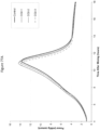
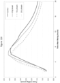
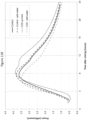
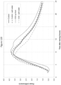
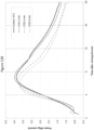
- Heat release during hydration is related to two somewhat overlapping peaks. The main heat release is related to the hydration of silicates, while a second heat release, observed as a hump on the downslope of the silicate peak, is associated with the hydration of the aluminates.
- Isothermal calorimetry testing is easy to carry out in mortar or even cement paste with very minimal sample preparation compared to the making of concrete samples, thus allowing for a rapid and convenient method of determining an optimal CO 2 dose and timing for a given cement, by testing a range of doses and delivery times.
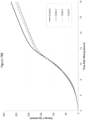
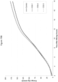
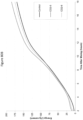
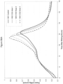
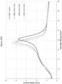
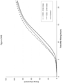
- the results obtained are either in the form of heat flow rate over time (also referred to as power vs. time herein), which describes the rate of cement hydration, or in the form of heat of hydration over time, which is the integrated heat flow rate (also referred to as energy vs. time herein). See, e.g., Example 30, which describes several different doses of carbon dioxide added to concrete in the drum of a ready mix truck, in trials conducted on two separate days.
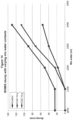
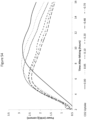
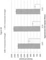
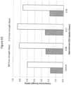
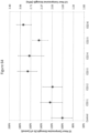
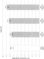
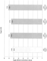
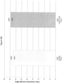
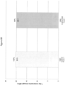
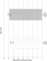
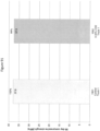
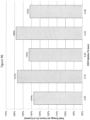
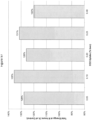
- Figures 81-85 show the absolute and relative compressive strengths of samples from the different doses of carbon dioxide, at different time points, for the first day; it can be seen that as carbon dioxide dose increased, strength at all time points generally increased.
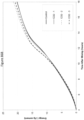
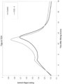
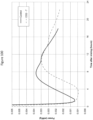
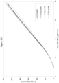
- the isothermal calorimetry curves shown in Figures 86A and 86B mirror this, with the highest dose of carbon dioxide causing the greatest shift in the curve, and second and third highest doses giving the second and third greatest shifts in the curves. Similar results can be seen in other Examples, e.g., Example 30 and others.
- Cements that are suitable for carbonation - with respect to accelerated set and/or early strength development - can be readily identified, and/or a dose or doses selected, as well as time of dosing, from the isocalorimetry curves using any suitable procedure, such as a procedure in which a cement paste, mortar, or concrete is produced using the cement being tested.
- Admixtures may also be tested, either separately or as part of an overall protocol, to determine their effects on workability and other desired characteristics, as well as optimal doses.
- samples can be prepared for testing of strength development, to verify the calorimetry results.
- admixtures are used to restore workability in order to generate well compacted samples with reliable strength data. Doses for carbon dioxide and, optionally, types and doses of admixture, for a given mix may thus be determined rapidly and efficiently, then the dose determined in the testing is used in the actual carbonation.
- Carbon dioxide can be supplied to a mix before the first addition of water, for example by flooding a chamber or head space with carbon dioxide before water addition, but in this case the application of carbon dioxide is considered to occur when the first water is added, since virtually no reaction will occur until the carbon dioxide dissolves in the mix water.
- precast operations there is little flexibility as to when carbon dioxide is added to the mixing concrete, as mix times are generally very short and the concrete is typically used very quickly after mixing.
- addition of carbon dioxide to the mixing concrete generally begins simultaneously with the commencement of mixing or within seconds or, at most, minutes of the commencement of mixing.
- ready-mix operations there are several times at which carbon dioxide can be added to the mixing concrete.
- Carbon dioxide can be added during batching, which can occur either in a fixed mixer or in the drum of the ready-mix truck; in this case, the carbon dioxide contacts the hydrating cement at a time very close to the commencing of mixing, as in the precast case.
- Some ready-mix operations include one or more additional operations after batching but before the truck has left the batching facility, e.g., a wash station for washing the truck after batching, and in these operations carbon dioxide may be alternatively or additionally added at the batching facility after batching, e.g., at a wash station, which will involve carbon dioxide addition at a time several minutes after mixing commences. Additionally or alternatively, carbon dioxide may be added at the job site after the concrete has been transported, and in these cases carbon dioxide addition will be added to mixing concrete at a time up to several hours after mixing commences. Any suitable combination of these approaches may be used.
- carbon dioxide is applied to the mix at 0 minutes, that is, carbon dioxide is present to the mix chamber when the first mix water is supplied, or supplying carbon dioxide to the mix chamber commences when the first mix water is applied, or both.
- carbon dioxide is applied at least 0, 1, 5, 10, 20, 30, 40, or 50 seconds, or 1, 2, 5, 10, 15, 20, 30, 40, 50, 60, 70, 80, or 90 minutes after mixing commences, and/or not more than 1, 2, 5, 10, 15, 20, 30, 40, 50, 60, 70, 80, 90, 120, 180, 240, or 300 minutes after mixing commences.
- the duration of carbon dioxide delivery can be less than or equal to 10, 8, 7, 6, 5, 4, 3, 2, or 1 minute, or less than or equal to 50, 40, or 30 seconds, and/or more than or equal to 5, 10, 20, 30, 40, or 50 seconds, or more than or equal to 1, 2, 3, 4, 5, 6, 7, or 8 minutes. In certain embodiments, the duration of carbon dioxide delivery is 5 seconds to 5 minutes. In certain embodiments, the duration of carbon dioxide delivery is 10 seconds to 4 minutes. In certain embodiments, the duration of carbon dioxide delivery is 20 seconds to 3 minutes. In certain embodiments, carbon dioxide delivery commences not more than 1 minute after mixing commences.
- the mix components may be added to the truck, and it may be desirable that carbon dioxide addition not commence until at least 2, 3 or 4 minutes or more after mixing has commenced.
- Such addition could occur, e.g., at a wash station, where the driver stops to wash the truck before commencing delivery; the truck is usually stopped at the wash station for at least 5-10 minutes, and an on-site carbon dioxide delivery system can be used to supply carbon dioxide to the drum of the truck during the wash station stop.
- Part or all of the dose of carbon dioxide can be delivered in this manner, for example by delivering carbon dioxide to the truck through the water line (though any suitable route may be used); in embodiments where a carbon dioxide source is attached to the truck there may be some mechanism to remind the driver to detach it before departing, such as an alarm.
- the desirable time for addition of carbon dioxide to the mix may be later in the mix time, such as at a time that the truck is normally en route to the job site, or at the job site.
- a portable source of carbon dioxide may be attached to the truck, with suitable valving and tubing, so as to deliver one or more doses of carbon dioxide to the drum of the truck at a later time, such as at least 15, 30, or 60 minutes after mixing commences.
- a controller which may be self-contained or may be remotely activated and which may send signals to a remote site regarding dosing and other information, may be included in the system so that dosing commences at a predetermined time after mixing commences and continues for a predetermined time, or continues until some predetermined characteristic or characteristics of the concrete mix is detected.
- the time and/or duration of dosing may be manually controlled, or subject to manual override.
- the carbon dioxide source can be as simple as a pressurized tank of gaseous carbon dioxide, which can be topped off periodically, for example when the truck returns to the batching site, to ensure a sufficient supply of carbon dioxide for any ensuing round of carbonation, e.g., without the need to ascertain carbon dioxide levels in the tank.
- some or all of the carbonation may occur at the job site, for example, based on determination of one or more characteristics of the concrete.
- the rate of delivery of the carbon dioxide may be any desired rate and the rate may be controlled.
- a slower rate of delivery may be desired, especially in wet mix operations such as ready mix operations, where the higher w/c ratio is known to slow carbonation compared to lower w/c operations, e.g., some precast operations.
- One example for controlling the rate of delivery is to divide the total dose of carbon dioxide into two or more smaller doses.
- the carbon dioxide may be delivered as a single dose, or as multiple doses, for example, as at least 2, 3, 4, 5, 6, 7, 8, 9, or 10 doses, and/or not more than 3, 4, 5, 6, 7, 8, 9, 10, 12, 15, or 20 doses; such as 2-10 doses, or 2-5 doses.
- Each dose may be equal in size to the others or different, and the interval between doses may be timed equally or not, as desired.
- the exact number and size of the doses may be predetermined, or it may be dictated by one or more characteristics of the mix that are monitored.
- the carbon dioxide may be in any suitable form, such as gas, or a gas/solid mix.
- gaseous carbon dioxide carbon dioxide may be delivered at a controlled, relatively slow rate.
- the carbon dioxide is delivered at least in part as a gas at a controlled rate, where the rate may be not more than 5, 10, 20, 30, 40, 50, 60, 70, 80, 90, 100, 120, 150, 200, 300, 400, 500, 600, 700, or 800 SLPM (standard liters per minute), and or not less than 10, 20, 30, 40, 50, 60, 70, 80, 90, 100, 120, 150, 200, 300, 400, 500, 600, 700, 800, or 900 SLPM.
- the carbon dioxide may be delivered at a rate such that the full dose is delivered while the truck is in transit, e.g., by a portable dosing system as described above, over a period of many minutes or even an hour or more, such as at a rate of 100 to 600 SLPM, or even lower rates.
- the rate of delivery may be constant, or it may be varied according to a predetermined schedule, or as dictated by one or more characteristics of the concrete mix that are monitored. Either or both of divided doses and controlled rate dosing may be used, as desired or dictated by the particular mix and job requirements.
- the methods and compositions of the invention allow for very high levels of efficiency of uptake of carbon dioxide into the mixing concrete, where the efficiency of uptake is the ratio of carbon dioxide that remains in the mixing concrete as stable reaction products to the total amount of carbon dioxide to which the mixing concrete is exposed.
- the efficiency of carbon dioxide uptake is at least 40, 50, 60, 70, 80, 90, 95, 96, 97, 98, 99, or 99%, or 40-100, 50-100, 60-100, 70-100, 80-100, 90-100, 40-99, 50-99, 60-99, 70-99, 80-99, or 90-99%.
- the addition of carbon dioxide, components of the cement mix, e.g., hydraulic cement mix, such as one or more admixtures, described more fully below may be adjusted so that flowability of the final cement mix, e.g., hydraulic cement mix is within 10% of the flowability that would be achieved without the addition of carbon dioxide .
- the addition of carbon dioxide, components of the cement mix, e.g., hydraulic cement mix, such as one or more admixtures, described more fully below are adjusted so that flowability of the final cement mix, e.g., hydraulic cement mix is within 50, 40, 30, 20 15, 10, 8, 5, 4, 3, 2, or 1% of the flowability that would be achieved without the addition of carbon dioxide, or of a predetermined flowability.
- the addition of carbon dioxide, components of the cement mix, e.g., hydraulic cement mix, such as one or more admixtures, described more fully below, are adjusted so that flowability of the final cement mix, e.g., hydraulic cement mix is within 20% of the flowability that would be achieved without the addition of carbon dioxide, or a predetermined flowability.
- the addition of carbon dioxide, components of the cement mix, e.g., hydraulic cement mix, such as one or more admixtures, described more fully below are adjusted so that flowability of the final cement mix, e.g., hydraulic cement mix is within 10% of the flowability that would be achieved without the addition of carbon dioxide, or a predetermined flowability.
- the addition of carbon dioxide, components of the cement mix, e.g., hydraulic cement mix, such as one or more admixtures, described more fully below, are adjusted so that flowability of the final cement mix, e.g., hydraulic cement mix is within 5% of the flowability that would be achieved without the addition of carbon dioxide, or a predetermined flowability.
- the addition of carbon dioxide, components of the cement mix, e.g., hydraulic cement mix, such as one or more admixtures, described more fully below are adjusted so that flowability of the final cement mix, e.g., hydraulic cement mix is within 2% of the flowability that would be achieved without the addition of carbon dioxide, or a predetermined flowability.
- the addition of carbon dioxide, components of the cement mix, e.g., hydraulic cement mix, such as one or more admixtures, described more fully below, are adjusted so that flowability of the final cement mix, e.g., hydraulic cement mix is within 1-50%, or 1-20%, or 1-10%, or 1-5%, or 2-50%, or 2-20%, or 2-10%, or 2-5% of the flowability that would be achieved without the addition of carbon dioxide, or a predetermined flowability.
- Admixtures are often used in cement mix, e.g., hydraulic cement mixes, such as concrete mixes, to impart desired properties to the mix.
- Admixtures are compositions added to a cement mix, e.g., hydraulic cement mix such as concrete to provide it with desirable characteristics that are not obtainable with basic cement mix, e.g., hydraulic cement mixes, such as concrete mixtures or to modify properties of the cement mix, e.g., hydraulic cement mix, i.e., concrete to make it more readily useable or more suitable for a particular purpose or for cost reduction.
- An admixture is any material or composition, other than the hydraulic cement, aggregate and water, that is used as a component of the cement mix, e.g., hydraulic cement mix, such as concrete or mortar to enhance some characteristic, or lower the cost, thereof.
- the desired cement mix e.g., hydraulic cement mix, e.g., concrete performance characteristics can only be achieved by the use of an admixture.
- using an admixture allows for the use of less expensive construction methods or designs, the savings from which can more than offset the cost of the admixture.
- the carbonated cement mix e.g., hydraulic cement mixture, e.g., concrete
- the carbonated cement mix may exhibit enhanced characteristics when compared with the same mixture that was not exposed to carbon dioxide. This can depend on the type of cement used in the carbonated cement mix and/or the dose of carbon dioxide used and final carbonation achieved. In this sense, carbon dioxide can itself act as an admixture.
- the carbonated cement mix, e.g., concrete mixture has superior properties such as greater strength, such as greater 1-, 7-, or 28-day strength, e.g., at least 1, 2, 3, 4, 5, 7, 10, 15, 20, 30, or 40% greater strength than the non-carbonated concrete mixture at 1-, 7-, or 28-days.
- the carbonated cement mix e.g. concrete
- may exhibit accelerated set compared to non-carbonated mix such as a faster time to initial set (for example, penetrometer measurement of 500 psi according to ASTM C403) or a faster time to final set (for example, penetrometer measurement of 4000 psi according to ASTM C403), or both, such as less than 95, 90, 85, 80, 75, 70, 65, 60, 55, 50, 40, 30, or 20% of the initial or final set time compared to uncarbonated mix.
- Carbonated cement mix may also provide final concrete mixtures that have lower water absorption as compared to non-carbonated, such as at least 1, 2, 3, 4, 5, 7, 10, 15, 20, 30, or 40% lower water absorption.
- the carbonated cement mix e.g., hydraulic cement mix, i.e., concrete, may also produce a final product that is lower in density but of comparable strength compared to non-carbonated, such as at least 1, 2, 3, 4, 5, 7, 10, 15, 20, 30, or 40% lower density with a compressive strength within 1, 2, 3, 4, 5, 7, 10, 15, or 20% of the non-carbonated, e.g., at least 5% lower density with a compressive strength within 2%.
- the carbonated cement mix e.g., hydraulic cement mixture, i.e., concrete
- the carbonated cement mix may alternatively or in addition, exhibit properties that it is desired to modulate, such as by the addition of an admixture.
- carbonated cement mix e.g., hydraulic cement mix for use in a wet cast operation may have workability/flow characteristics that are not optimum for a wet cast operation without addition of an admixture or other manipulation of the mix, e.g., addition of extra water.
- carbonated mixes may have strength characteristics, e.g., compressive strength at one or more time points, that are not optimum without addition of an admixture or other manipulation of the mix.
- the mix design will already call for an admixture, whose effect on the properties of the mix may be affected by the carbonation, requiring coordination of the timing of the admixture in relation to the carbon dioxide addition, or other manipulation.
- an admixture may be used to modulate one or more aspects of the carbonation itself, for example, to increase the rate of uptake of the carbon dioxide.
- Concrete may be used in wet cast operations, such as in certain precast operations or in ready mix trucks that transport the concrete to a job site where it is used, e.g., poured into molds or otherwise used at the site, or in dry cast operations, which are precast operations.
- wet cast operations the flowability of the concrete should be maintained at a level compatible with its use in the operation, e.g., in the case of a ready mix truck, at the job site; whereas for a dry cast operation concrete that does not flow (zero slump) is desirable.
- strength e.g., compressive strength
- Flowability of a mix may be evaluated by measuring slump; strength may be evaluated by one or more strength tests, such as compressive strength.
- carbonation of the cement mix may affect flowability of a cement mix, e.g., hydraulic cement mix, i.e., a concrete mix, to be used in a wet cast operation, such as in a ready mix truck transporting the mix to a job site.
- a cement mix e.g., hydraulic cement mix, i.e., a concrete mix
- one or more admixtures may be added to modulate the flowability of the carbonated mixture, either before, during, or after carbonation, or any combination thereof, such that it is within a certain percentage of the flowability of the same mixture without carbonation, or of a certain predetermined flowability.
- the addition of carbon dioxide, components of the mix, e.g., concrete mix, and/or additional components such as one or more admixtures may be adjusted so that flowability of the final mix is within 50, 40, 30, 20, 10, 8, 5, 4, 3, 2, 1, 0.5, or 0.1% of the flowability that would be achieved without the addition of carbon dioxide, or of a certain predetermined flowability.
- the addition of carbon dioxide, components of the mix, and/or additional components such as one or more admixtures may be adjusted so that flowability of the final mix is within 20% of the flowability that would be achieved without the addition of carbon dioxide, or within 20% of a predetermined desired flowability.
- the addition of carbon dioxide, components of the mix, and/or additional components such as one or more admixtures may be adjusted so that flowability of the final mix is within 10% of the flowability that would be achieved without the addition of carbon dioxide, or within 10% of a predetermined desired flowability. In certain embodiments, the addition of carbon dioxide, components of the mix, and/or additional components such as one or more admixtures, may be adjusted so that flowability of the final mix is within 5% of the flowability that would be achieved without the addition of carbon dioxide, or within 5% of a predetermined desired flowability.
- the addition of carbon dioxide, components of the mix, and/or additional components such as one or more admixtures may be adjusted so that flowability of the final mix is within 2% of the flowability that would be achieved without the addition of carbon dioxide, or within 2% of a predetermined desired flowability.
- Any suitable measurement method for determining flowability may be used, such as the well-known slump test.
- Any suitable admixture may be used, as described herein, such as carbohydrates or carbohydrate derivatives, e.g., fructose, sucrose, glucose, sodium glucoheptonate, or sodium gluconate, such as sodium glucoheptonate or sodium gluconate.
- one or more admixtures may be added to modulate the mix so that a desired strength, either early strength, late strength, or both, may be achieved.
- Strength of the carbonated cement mix can be dependent on mix design, thus, although with some mix designs carbonation may increase strength at one or more time points, in other mix designs carbonation may decrease strength at one or more time points. See Examples for various mix designs in which carbonation increased or decreased strength at one or more time points. In some cases, carbonation decreases strength at one or more time points and it is desired to return the strength at the time point to within a certain acceptable limit.
- one or more admixtures is added to increase strength beyond that seen in non-carbonated concrete of the same density.
- This may be done, e.g., to produce a lightweight concrete with strength comparable to the denser, non-carbonated concrete.
- one or more admixtures added to a carbonated cement itself causes or exacerbates strength loss, and it is desired to recover the loss.
- an admixture is added to the carbonated mix, either before, during, or after carbonation, or a combination thereof, under conditions such that the carbonated mix exhibits strength, e.g., 1-, 7-, 28 and/or 56-day compressive strength, within a desired percentage of the strength of the same mix without carbonation, or of a predetermined strength, e.g., within 50, 40, 30, 20, 15, 12, 10, 9, 8, 7, 6, 5, 4, 3, 2, 1, 0.5, or 0.1%.
- strength e.g., 1-, 7-, 28 and/or 56-day compressive strength
- the addition of carbon dioxide, components of the mix, and/or additional components such as one or more admixtures may be adjusted so that strength at a given time point of the final mix is within 20% of the strength that would be achieved without the addition of carbon dioxide, or within 20% of a predetermined desired strength. In certain embodiments, the addition of carbon dioxide, components of the mix, and/or additional components such as one or more admixtures, may be adjusted so that strength at a given time point of the final mix is within 10% of the strength that would be achieved without the addition of carbon dioxide, or within 10% of a predetermined desired strength.
- the addition of carbon dioxide, components of the mix, and/or additional components such as one or more admixtures may be adjusted so that strength at a given time point of the final mix is within 5% of the strength that would be achieved without the addition of carbon dioxide, or within 5% of a predetermined desired strength.
- the addition of carbon dioxide, components of the mix, and/or additional components such as one or more admixtures may be adjusted so that strength at a given time point of the final mix is within 2% of the strength that would be achieved without the addition of carbon dioxide, or within 2% of a predetermined desired strength.
- the strength is a compressive strength. Any suitable method to test strength, such as flexural or compressive strength, may be used so long as the same test is used for samples with and without carbonation. Any suitable admixtures to achieve the desired strengths may be used, such as the admixtures described herein.
- more than one admixture may be used, for example, 2, 3, 4, 5, or more than 5 admixtures.
- certain admixtures have desirable effects on flowability but undesirable effects on strength development; when such an admixture is used, a second admixture that accelerates strength development may also be used.
- any suitable admixture that has the desired effect on the property or properties of the carbonated cement that it is desired to modified may be used.
- TABLE 1 lists exemplary classes and examples of admixtures that can be used, e.g., to modulate the effects of carbonation.
- one or admixtures is added to a cement mix, e.g., hydraulic cement mix, before, during, or after carbonation of the mix, or a combination thereof, where the admixture is a set retarder, plasticizer, accelerant, or air entraining agent.
- a cement mix e.g., hydraulic cement mix
- the admixture is a set retarder, plasticizer, accelerant, or air entraining agent.
- set retarders and plasticizers are useful.
- accelerants are useful.
- certain air entraining agents may be useful.
- Set retarders include carbohydrates, i.e., saccharides, such as sugars, e.g., fructose, glucose, and sucrose, and sugar acids/bases and their salts, such as sodium gluconate and sodium glucoheptonate; phosphonates, such as nitrilotri(methylphosphonic acid), 2-phosphonobutane-1,2,4-tricarboxylic acid; and chelating agents, such as EDTA, Citric Acid, and nitrilotriacetic acid.
- Other saccharides and saccharide-containing admixes include molasses and corn syrup. In certain embodiments, the admixture is sodium gluconate.
- exemplary admixtures that can be of use as set retarders include sodium sulfate, citric acid, BASF Pozzolith XR, firmed silica, colloidal silica, hydroxyethyl cellulose, hydroxypropyl cellulose, fly ash (as defined in ASTM C618), mineral oils (such as light naphthenic), hectorite clay, polyoxyalkylenes, natural gums, or mixtures thereof, polycarboxylate superplasticizers, naphthalene HRWR (high range water reducer).
- Additional set retarders that can be used include, but are not limited to an oxy-boron compound, lignin, a polyphosphonic acid, a carboxylic acid, a hydroxycarboxylic acid, polycarboxylic acid, hydroxylated carboxylic acid, such as fumaric, itaconic, malonic, borax, gluconic, and tartaric acid, lignosulfonates, ascorbic acid, isoascorbic acid, sulphonic acid-acrylic acid copolymer, and their corresponding salts, polyhydroxysilane, polyacrylamide.
- Illustrative examples of retarders are set forth in U.S. Pat. Nos. 5,427,617 and 5,203,919 , incorporated herein by reference.
- Accelerants include calcium-containing compounds, such as CaO, Ca(NO 2 ) 2 , Ca(OH) 2 , calcium stearate, or CaCl 2 , and magnesium-containing compounds, such as magnesium hydroxide, magnesium oxide, magnesium chloride, or magnesium nitrate.
- the added calcium or magnesium compound may provide free calcium or magnesium to react with the carbon dioxide, providing a sink for the carbon dioxide that spares the calcium in the cement mix, or providing a different site of carbonation than that of the cement calcium, or both, thus preserving early strength development.
- CaO (lime) may be added to the mix, or a high-free lime cement may be the preferred cement for the mix.
- the free lime (CaO) content of the cement used in a particular cement mixture, such as mortar or concrete may be increased by the addition of CaO to the mixture, generally before the mixture is exposed to carbon dioxide, such as by addition of 0.01-50%, or 0.01-10%, or 0.01-5%, or 0.01-3%, or 0.01-2%, or 0.01-1% CaO, or 0.1-50%, or 0.1-10%, or 0.1-5%, or 0.1-3%, or 0.1-2% , or 0.1-1%, or 0.2-50%, or 0.2-10%, or 0.2-5%, or 0.2-3%, or 0.2-2% CaO, or 0.2-1%, or 0.5-50%, or 0.5-10%, or 0.5-5%, or 0.5-3%, or 0.5-2% CaO, or 0.5-1% CaO bwc.
- CaO may be added so that the overall CaO content of the cement mixture reaches a desired level, such as 0.5-10%, or 0.5-5%, or 0.5-3%, or 0.5-2%, or 0.5-1.5%, or at least 0.5, 0.6, 0.7, 0.8, 0.9, 1.0, 1.1, 1.2, 1.3, 1.4, 1.5, 1.6, 1.7, 1.8, 1.9, 2.0, 2.2, 2.5, 3.0, 4.0, 5.0, 6.0, 7.0, 8.0, 9.0, 10%, 20%, 30%, 40%, or 50% CaO bwc.
- a desired level such as 0.5-10%, or 0.5-5%, or 0.5-3%, or 0.5-2%, or 0.5-1.5%, or at least 0.5, 0.6, 0.7, 0.8, 0.9, 1.0, 1.1, 1.2, 1.3, 1.4, 1.5, 1.6, 1.7, 1.8, 1.9, 2.0, 2.2, 2.5, 3.0, 4.0, 5.0, 6.0, 7.0,
- the added CaO will generally also increase the rate of uptake of carbon dioxide by the mix during mixing, thus allowing a greater carbon dioxide uptake for a given time of exposure, or a lower time of exposure to achieve a given level of uptake.
- Other set accelerators include, but are not limited to, a nitrate salt of an alkali metal, alkaline earth metal, or aluminum; a nitrite salt of an alkali metal, alkaline earth metal, or aluminum; a thiocyanate of an alkali metal, alkaline earth metal or aluminum; an alkanolamine; a thiosulfate of an alkali metal, alkaline earth metal, or aluminum; a hydroxide of an alkali metal, alkaline earth metal, or aluminum; a carboxylic acid salt of an alkali metal, alkaline earth metal, or aluminum (preferably calcium formate); a polyhydroxylalkylamine; a halide salt of an alkali metal or alkaline earth metal (e.g.,
- the admixture or admixtures may be added to any suitable final percentage (bwc), such as in the range of 0.01-0.5%, or 0.01-0.3%, or 0.01-0.2%, or 0.01-0.1%, or 0.01-1.0%, or 0.01-0.05%, or 0.05% to 5%, or 0.05% to 1%, or 0.05% to 0.5%, or 0.1% to 1%, or 0.1% to 0.8%, or 0.1% to 0.7% per weight of cement.
- bwc final percentage
- the admixture may be added to a final percentage of greater than 0.01, 0.02, 0.03, 0.04, 0.05, 0.06, 0.07, 0.08, 0.09, 0.1, 0.15, 0.2, 0.3, 0.4, or 0.5%; in certain cases also less than 5, 4, 3, 2, 1, 0.9, 0.8, 0.7, 0.6, 0.5, 0.4, 0.3, 0.2, 0.1, 0.09, 0.08, 0.07, 0.06, 0.05, 0.04, 0.03, or 0.02%.
- timing of addition of a given admixture relative to carbonation of a cement mix may alter the effects of the admixture on the properties of the cement mix, e.g., hydraulic cement mix, e.g., effects on flowability or strength.
- a cement mix e.g., hydraulic cement mix
- effects on flowability or strength e.g., effects on flowability or strength.
- the addition of sodium gluconate after carbonation restores flowability to desired levels, but may adversely affect early strength development; whereas the addition of sodium gluconate before carbonation maintains early strength development but does not optimally restore flowability.
- the air entrainer is added before carbonation, the density of the mix is increased compared to if the air entrainer is added after carbonation.
- the admixture or admixtures thus may be added before, during, or after carbonation of the cement mix, e.g., hydraulic cement mix, or any combination thereof.
- the admixture is added after carbonation; in other embodiments, the admixture is added before carbonation; in yet other embodiments, the admixture is added in two split doses, one before carbonation and one during and/or after carbonation.
- carbonation and of admixtures on carbonated cement mix e.g., hydraulic cement mixes is highly mix-specific.
- carbonation actually improves the properties of a mix, especially in dry cast situations where flowability is not an issue, and no admixture is required.
- one or more admixtures may be required to restore one or more properties of the mix. Whether or not admixture is added, and/or how much is added, to a given batch may be determined by pre-testing the mix to determine the properties of the carbonated mix and the effects of a given admixture.
- the admixture and/or amount may be predicted based on previous tests, or on properties of the cement used in the mix, or on theoretical considerations. It has been found that different cements have different properties upon carbonation, and also react differently to a given admixture, and the invention includes the use of a library of data on various cement types and admixtures so as to predict a desired admixture/amount for a mix design, which may be a mix that is the same as or similar to a mix in the library, or a new mix whose properties can be predicted from the library.
- rheology flowability
- flowability may be monitored during the carbonation of the batch and the exact timing and/or amount of admixture added to that particular batch, or to subsequent batches, may be adjusted based on the feedback obtained.
- a combination of predicted value for admixture type, timing, and/or amount, and modification of the value based on real-time measurements in a given batch or batches may be used.
- an admixture comprising a carbohydrate or carbohydrate derivative is added to a cement mix, e.g., hydraulic cement mix before, during, and/or after carbonation of the mix, or a combination thereof.
- the admixture is added after carbonation of the cement mix, e.g., hydraulic cement mix, or during and after carbonation.
- the carbonation may be accomplished as described herein, for example, by delivering carbon dioxide to the surface of the cement mix, e.g., hydraulic cement mix during mixing.
- the carbohydrate or derivative may be any carbohydrate as described herein, for example sucrose, fructose, sodium glucoheptonate, or sodium gluconate.
- the carbohydrate is sodium gluconate.
- the carbohydrate or derivative, e.g., sodium gluconate may be used at a suitable concentration; in some cases, the concentration is greater than 0.01%, 0.015%, 0.02%, 0.025%, 0.03%, 0.035%, 0.04%, 0.05%, 0.06%, 0.07%, 0.08%, 0.09%, 0.1%, 0.15%, 0.2%, 0.3%, 0.4%, or 0.5% bwc.
- the concentration may also be less than 2, 1.5, 1, 0.9, 0.8, 0.7, 0.6, 0.5, 0.4, 0.3, 0.2, or 0.1%.
- sodium gluconate is used as an admixture at a dose of between 0.01 and 1% bwc, or between 0.01 and 0.8%, or between 0.01 and 0.5%, or between 0.01 and 0.4% bwc, or between 0.01 and 0.3%, or between 0.01 and 0.2% bwc, or between 0.01 and 0.1%, or between 0.01 and 0.05%, or between 0.03 and 1% bwc, or between 0.03 and 0.8%, or between 0.03 and 0.5%, or between 0.03 and 0.4% bwc, or between 0.03 and 0.3%, or between 0.03 and 0.2% bwc, or between 0.03 and 0.1%, or between 0.03 and 0.08%, or between 0.05 and 1% bwc, or between 0.05 and 0.8%, or between 0.05 and 0.5%, or between 0.05 and 0.4% bwc, or between 0.05 and 0.3%, or between 0.05 and 0.2% bwc, or between 0.05 and 0.1%, or between 0.05 and 0.08%, or between 0.05 and 0.
- the sodium gluconate may be added before, during, or after carbonation of the mix, or any combination thereof, and may be added as one, two, three, four, or more than four divided doses.
- the carbohydrate or derivative may be added in two or more doses, such as one dose before carbonation and one dose during and/or after carbonation.
- calcium stearate is used as an admixture.
- a second admixture is also used, such as any of the admixtures described herein.
- the second admixture is a strength accelerator.
- a third admixture is also used, such as any of the admixtures described herein.
- a fourth admixture is also used, such as any of the admixtures described herein.
- an admixture that modulates the formation of calcium carbonate so that one or more polymorphic forms is favored compared to the mixture without the admixture, e.g., modulates the formation of amorphous calcium carbonate, e.g., aragonite, or calcite.
- Exemplary admixtures of this type include organic polymers such as polyacrylate and polycarboxylate ether, phosphate esters such as hydroxyamino phosphate ester, phosphonate and phosphonic acids such as nitrilotri(methylphosphonic acid), 2-phosphonobutane-1,2,4-tricarboxylic acid, chelators, such as sodium gluconate, ethylenediaminetetraacetic acid (EDTA), and citric acid, or surfactants, such as calcium stearate.
- organic polymers such as polyacrylate and polycarboxylate ether, phosphate esters such as hydroxyamino phosphate ester, phosphonate and phosphonic acids such as nitrilotri(methylphosphonic acid), 2-phosphonobutane-1,2,4-tricarboxylic acid, chelators, such as sodium gluconate, ethylenediaminetetraacetic acid (EDTA), and citric acid, or surfactants, such as calcium
- one or more supplementary cementitious materials (SCMs) and/or cement replacements are added to the mix at the appropriate stage for the particular SCM or cement replacement.
- an SCM is used. Any suitable SCM or cement replacement may be used; exemplary SCMs include blast furnace slag, fly ash, silica fume, natural pozzolans (such as metakaolin, calcined shale, calcined clay, volcanic glass, zeolitic trass or tuffs, rice husk ash, diatomaceous earth, and calcined shale), and waste glass.
- Further cement replacements include interground limestone, recycled/waste plastic, scrap tires, municipal solid waste ash, wood ash, cement kiln dust, foundry sand, and the like.
- an SCM and/or cement replacement is added to the mix in an amount to provide 0.1-50%, or 1-50%, or 5-50%, or 10-50%, or 20-50%, or 1-40%, or 5-40%, or 10-50%, or 20-40% bwc.
- an SCM is used and the SCM is fly ash, slag, silica fume, or a natural pozzolan.
- the SCM is fly ash.
- the SCM is slag.
- the invention provides methods and compositions for the expanding the range of conditions under which an SCM may be used in a concrete mix by carbonating the mix.
- the range of conditions may include the temperature at which the SCM-containing mix may be used, or the amount of SCM that may be added while maintaining adequate early strength development, or the early strength for a given amount of SCM in a mix.
- the invention provides a method for decreasing the minimum temperature at which an SCM-concrete mix may be used, thus increasing the overall acceptable temperature range for the SCM-concrete mix, by exposing the SCM-concrete mix to a dose of carbon dioxide sufficient to modulate, e.g., accelerate, early strength development and/or set of the mix to a level at which the mix may be used at a temperature below that at which it could have been used without the carbon dioxide exposure.
- the dose can be such that the early strength development of the mix allows its use in a desired manner at a temperature that is at least 1, 2, 3, 4, 5, 6, 8, 9, or 10 °C below the temperature at which it could be used without the carbon dioxide treatment and/or not more than 2, 3, 4, 5, 6, 8, 9, 10, or 12 °C below the temperature at which it could be used without the carbon dioxide treatment.
- the dose of carbon dioxide added to the mix to achieve the desired increase in early strength development can be not more than 2.0, 1.5, 1.2, 1.0, 0.9, 0.8, 0.7, 0.6, 0.5, 0.4, 0.3, 0.2, 0.1, or 0.05% carbon dioxide bwc.
- the dose can be such that the early strength development of the mix, e.g., the strength at 8, 12, 16, 20, or 24 hours, or any other suitable time point for early strength development, is, on average, at least 1, 2, 5, 7, 10, 12, 15, 20, or 25% greater than the strength without the carbon dioxide dose, and is sufficient for the use for which the mix is intended.
- an alternative or additional marker other than early strength development such as a value from calorimetry as described elsewhere herein, may be used instead of or in addition to early strength measurements, for example, to determine the desired or optimal dose of carbon dioxide and/or dosing conditions.
- the carbon dioxide may be delivered as a single dose or multiple doses, and at any suitable rate or in any suitable form, as described elsewhere herein.
- the SCM can be any suitable SCM.
- the SCM is fly ash. In certain embodiments, the SCM is slag. In certain embodiments, the SCM-concrete mix is delivered to a job site in a ready mix truck, and the carbon dioxide is applied to the mix at the batching site, en route to the job site, or at the job site, or any combination thereof. In certain embodiments, the carbon dioxide is gaseous carbon dioxide. In certain embodiments, the carbon dioxide is dissolved in mix water. In certain embodiments, the carbon dioxide is solid carbon dioxide. In certain embodiments, a combination of gaseous carbon dioxide and carbon dioxide dissolved in mix water is used.
- the invention provides a method for increasing the maximum amount (proportion) of SCM that may be used in an SCM-concrete mix, thus increasing the overall acceptable range of amounts (proportions) of SCM for the SCM-concrete mix, by exposing an SCM-concrete mix that contains a proportion of SCM that would normally be higher than the acceptable proportion due to effects on early strength development, to a dose of carbon dioxide sufficient to modulate, e.g., accelerate, early strength development of the mix to a level at which the mix may be used for its normal purposes.
- the maximum acceptable proportion of SCM in the mix is increased by carbonation by at least 0.5, 1, 1.5, 2, 2.5, 3, 3.5, 4, 5, 6, 7, 8, 9, 10, 11, 12, 13, 14, 15, 16, 17, 18, 19, or 20% bwc and/or not more than 1, 1.5, 2, 2.5, 3, 3.5, 4, 5, 6, 7, 8, 9, 10, 11, 12, 13, 14, 15, 16, 17, 18, 19, 20, or 25% bwc, over the maximum acceptable proportion of SCM without carbonation.
- the dose of carbon dioxide to the mix can be not more than 2.0, 1.5, 1.2, 1.0, 0.9, 0.8, 0.7, 0.6, 0.5, 0.4, 0.3, 0.2, 0.1, or 0.05% carbon dioxide bwc, and/or not less than 2.5, 2.0, 1.5, 1.2, 1.0, 0.9, 0.8, 0.7, 0.6, 0.5, 0.4, 0.3, 0.2, or 0.1% carbon dioxide bwc.
- the SCM can comprises at least 1, 2, 3, 4, 5, 6, 7, 8, 9, 10, 12, 15, 20, or 30 % of the mix, and/or not less than 2, 3, 4, 5, 6, 7, 8, 9, 10, 12, 15, 20, 30 , 40, or 50% of the mix.
- the dose can be such that the early strength development of the mix, e.g., the strength at 8, 12, 16, 20, or 24 hours, or any other suitable time point for early strength development, is, on average, at least 1, 2, 5, 7, 10, 12, 15, 20, or 25% greater than the strength without the carbon dioxide dose.
- an alternative or additional marker other than early strength development such as a value from calorimetry as described elsewhere herein, may be used instead of or in addition to early strength measurements, for example, to determine the desired or optimal dose of carbon dioxide and/or dosing conditions.
- the carbon dioxide may be delivered as a single dose or multiple doses, and at any suitable rate or in any suitable form, as described elsewhere herein.
- the SCM can be any suitable SCM. In certain embodiments, the SCM is fly ash.
- the SCM is slag.
- the SCM-concrete mix is delivered to a job site in a ready mix truck, and the carbon dioxide is applied to the mix at the batching site, en route to the job site, or at the job site, or any combination thereof.
- the carbon dioxide is gaseous carbon dioxide.
- the carbon dioxide is dissolved in mix water.
- the carbon dioxide is solid carbon dioxide. In certain embodiments, a combination of gaseous carbon dioxide and carbon dioxide dissolved in mix water is used.
- the invention provides a method for accelerating the early strength development of an SCM-concrete mix, thus accelerating aspects of a job in which the SCM-concrete mix is used that require a certain strength before a next step may be taken (such as removing molds, adding a level of concrete, and the like), by exposing the SCM-concrete mix to a dose of carbon dioxide sufficient to modulate, e.g., accelerate, early strength development of the mix to a level at which the aspect of the job may be accelerated.
- the dose of carbon dioxide to the mix can be not more than 2.0, 1.5, 1.2, 1.0, 0.9, 0.8, 0.7, 0.6, 0.5, 0.4, 0.3, 0.2, 0.1, or 0.05% carbon dioxide bwc, and/or not less than 2.5, 2.0, 1.5, 1.2, 1.0, 0.9, 0.8, 0.7, 0.6, 0.5, 0.4, 0.3, 0.2, or 0.1% carbon dioxide bwc.
- the dose can be such that the early strength development of the mix, e.g., the strength at 8, 12, 16, 20, or 24 hours, or any other suitable time point for early strength development, is, on average, at least 1, 2, 5, 7, 10, 12, 15, 20, 25, 30, 35, or 40% greater than the strength without the carbon dioxide dose.
- the SCM can comprises at least 1, 2, 3, 4, 5, 6, 7, 8, 9, 10, 12, 15, 20, or 30 % of the mix, and/or not less than 2, 3, 4, 5, 6, 7, 8, 9, 10, 12, 15, 20, 30, 40, or 50% of the mix.
- an alternative or additional marker than early strength development such as a value from calorimetry as described elsewhere herein, may be used instead of or in addition to early strength measurements, for example, to determine the desired or optimal dose of carbon dioxide and/or dosing conditions.
- the carbon dioxide may be delivered as a single dose or multiple doses, and at any suitable rate or in any suitable form, as described elsewhere herein.
- the SCM can be any suitable SCM.
- the SCM is fly ash.
- the SCM is slag.
- the SCM-concrete mix is delivered to a job site in a ready mix truck, and the carbon dioxide is applied to the mix at the batching site, en route to the job site, or at the job site, or any combination thereof.
- the carbon dioxide is gaseous carbon dioxide.
- the carbon dioxide is dissolved in mix water.
- the carbon dioxide is solid carbon dioxide.
- a combination of gaseous carbon dioxide and carbon dioxide dissolved in mix water is used.
- the methods and apparatus described herein may include one or more control mechanisms, e.g., automatic control mechanisms, to modulate one or more aspects of the mix and carbonation operation, such as to modulate the contact of the cement mix, e.g., hydraulic cement mix with carbon dioxide and/or other components, such as one or more admixtures or water, as well as other aspects of the operation of the mixer, such as worker safety requirements, cooling of the cement mix, e.g., hydraulic cement mix, and the like.
- modulation may be achieved by human operators who control the necessary valves and the like to achieve a desired carbon dioxide exposure and/or other characteristic of the carbonated cement mix, but in general automatic control mechanisms are employed.
- the control may be based on any suitable parameter, such as feedback regarding one or more characteristics of the mix operation, timing, which may be a predetermined timing, or a combination thereof.
- Control systems and mechanisms can apply to a stationary mixer in a precast concrete plant or other central mixing facility. Alternatively, it can apply to a ready mix concrete truck that facilitates mixing through rotation of its drum.
- the mix operation can be a dry cast or wet cast operation; for example, the ready mix concrete truck will be a wet cast, while precast may be wet cast or dry cast.
- the methods include modulating the flow of carbon dioxide to the cement mix, e.g., hydraulic cement mix according to a certain timing.
- the timing may be controlled by a controller that is connected to a cement mix, e.g., hydraulic cement mix apparatus and that senses when the apparatus has begun or stopped a stage of operation, and that modulates carbon dioxide flow accordingly, e.g., starts or stops flow.
- carbon dioxide flow is begun when one or more components of a cement mix, e.g., hydraulic cement mix have been deposited in a mixer, continues for a certain predetermined time at a certain predetermined flow rate, then stops.
- the stage of operation of the cement mix e.g., hydraulic cement mix apparatus may be determined by the programming of the controller or of another controller to which the controller is operably connected, or it may be determined by one or more sensors which monitor positions of components of the apparatus, flow, and the like, or a combination thereof.
- control systems and mechanisms of the invention include feedback mechanisms where one or more characteristics of the cement mix, e.g., hydraulic cement mixture and/or apparatus or its environment is monitored by one or more sensors, which transmit the information to a controller which determines whether one or more parameters of the mix operation requires modulation and, if so, sends the appropriate output to one or more actuators to carry out the required modulation.
- the controller may learn from the conditions of one batch to adjust programming for subsequent batches of similar or the same mix characteristics to optimize efficiency and desired characteristics of the mix.
- various aspects of the mix operation, the mixer, the cement mix, e.g., hydraulic cement mix, and the environment of the mixer may be monitored, the information from the monitoring processed, and adjustments made in one or more aspects of the mix operation in order to achieve the desired result.
- one or more sensors may be used to provide input to a controller as to various conditions related to the desired characteristics; the controller processes the inputs and compares them to predetermined parameters of operation and, if corrections in the process are necessary, the controller then sends output to one or more actuators in order to bring the system back toward the desired condition.
- the invention provides control systems for controlling the carbonation of a cement mix, e.g., hydraulic cement mix in a mixer by use of one or more sensors monitoring one or more of weight of the cement used in the mix, carbon dioxide concentration of the atmosphere inside and/or outside the mixer, temperature of the cement mix, e.g., hydraulic cement mix or a component in contact with the cement mix, e.g., hydraulic cement mix, rheology of the mix, and/or moisture content of the mix, where the one or more sensors send input to a controller which processes the information received from the one or more sensors by comparing the input to one or more predetermined parameters and, if necessary, sends output to one or more actuators to adjust carbon dioxide flow rate, water addition, or admixture addition, or to perform other functions such as to sound an alarm if carbon dioxide levels exceed safe levels.
- a cement mix e.g., hydraulic cement mix in a mixer by use of one or more sensors monitoring one or more of weight of the cement used in the mix, carbon dioxide concentration of the atmosphere inside and/or
- certain operations such as cooling of the cement mix, e.g., hydraulic cement mix, may be performed after the mixing is complete.
- the controller can learn from one batch to adjust conditions for a subsequent batch of the same or similar composition.
- Further levels of control may be used, such as a central controller that receives information from a plurality of mix operations in a plurality of locations regarding one or more aspects of each operation, and processes the information received from all mix operations to improve performance at the various operations; thus, large amounts of information can be used to improve performance at a variety of sites.
- components of the cement mix e.g., hydraulic cement mix, e.g., cement, aggregate, and water
- components of the cement mix e.g., hydraulic cement mix, e.g., cement, aggregate, and water
- components of the cement mix e.g., hydraulic cement mix, e.g., cement, aggregate, and water
- some components, such as aggregate may have a sufficient water content, e.g., from exposure to wet weather conditions, that additional water is not added before mixing commences.
- water or other components may be added in a staged manner.
- carbon dioxide flow is initiated from a source of carbon dioxide to the mixer. In some cases, part or all of the carbon dioxide will be included in the mix water.
- the carbon dioxide flow will be gaseous; in other cases, the carbon dioxide flow comprises a mixture of gaseous and solid carbon dioxide. Additional components, such as admixtures, may be added to the cement mix, e.g., hydraulic cement mix as well at any point in the operation.
- the carbon dioxide is subsumed into the mixing cement mix, e.g., hydraulic cement mix and begins reaction with the mix components; any carbon dioxide that is not taken up by the cement mix, e.g., hydraulic cement mix fills the head space of the mix container.
- the rate of carbon dioxide flow to the mixer exceeds the rate of uptake into the cement mix, e.g., hydraulic cement mix, at some point the head space in the mixer will be full of carbon dioxide and excess carbon dioxide will exit the mixer from one or more leak points.
- the carbon dioxide content of the atmosphere inside the mixer or, more preferably, outside the mixer, e.g., at one or more leak points may be monitored to provide an indication that the rate of carbon dioxide addition is exceeding the rate of carbon dioxide uptake.
- carbon dioxide levels in areas where workers are likely to be may also be monitored as a safety precaution.
- the reaction of carbon dioxide with the hydraulic cement is exothermic, thus the temperature of the cement mix, e.g., hydraulic cement mix rises; the rate of temperature rise is proportional to the rate of carbon dioxide uptake and the overall temperature rise is proportional to total carbon dioxide uptake for a given mix design.
- the temperature of the cement mix e.g., hydraulic cement mix, or the temperature of one or more portions of the mix container or other equipment that are in contact with the mix, may be monitored as an indication of rate and extent of carbon dioxide uptake into the cement mix, e.g., hydraulic cement mix.
- Carbonation of components of the cement mix may produce a change in the flow characteristics, i.e., rheology, of the cement mix, e.g., hydraulic cement mix, which can be undesirable in certain applications, e.g., in wet cast applications such as in a ready mix truck.
- the rheology of the cement mix e.g., hydraulic cement mix may be monitored.
- carbonation may affect the moisture characteristics of the cement mix, e.g., hydraulic cement mix, which may lead to undesirable characteristics, and moisture content of the mix may be monitored as well.
- the invention also provides a network of mix systems with one or more sensors and, optionally, controllers, that includes a plurality of mix systems, such as 2, 3, 4, 5, 6, 7, 8, 9, 10, or more than 10 mix systems with one or more sensors and, optionally, controllers, each of which transmits data from their respective locations and mix conditions to a central controller, which learns from the overall data from all the mix systems and provides updated and modified mix instructions to the various mix systems in the network based on this information. In this way the operation of each individual mix system within the network can be optimized based on information from all the other mix systems in the network.
- timing and extent of carbon dioxide delivery, admixture type and amount, water amount and timing and delivery, and other factors may be optimized for one site before it has even begun its first batch, based on historical information from other sites, and all sites may undergo continual improvement in optimization as the sensors, and, optionally, controllers in the network continually gain more information and feed it to the central controller.
- the methods and/or apparatus may include feedback mechanisms by which one or more characteristics of the type of mixer apparatus, cement mix, e.g., hydraulic cement mix, a gas mixture in contact with the cement mix, e.g., hydraulic cement mix and inside or outside of the mixer, a component of the cement mix, e.g., hydraulic cement mix production apparatus, a component exposed to the cement mix, e.g., hydraulic cement mix, or the environment of the mixer, is monitored and the information is used to modulate the exposure of the cement mix, e.g., hydraulic cement mix to carbon dioxide, one or more admixtures, water, or other components, in the current mix and/or in subsequent mixes.
- cement mix e.g., hydraulic cement mix
- a gas mixture in contact with the cement mix e.g., hydraulic cement mix and inside or outside of the mixer
- a component of the cement mix e.g., hydraulic cement mix production apparatus
- a component exposed to the cement mix e.g., hydraulic cement mix, or the environment of the mixer
- Characteristics such as carbon dioxide content monitored inside and/or outside the mixer, and/or temperature of the mix monitored inside the mixer or outside of the mixer, of a component in contact with the cement mix, e.g., hydraulic cement mix, e.g., a surface of the mixer such as the outer surface of the mixer, and/or position or state of operation of a component of the cement mix, e.g., hydraulic cement mix production apparatus, may be used to determine when to modulate carbon dioxide addition, e.g., to start or to stop or slow carbon dioxide addition. Certain safety monitoring may also be done, e.g., monitoring of areas outside the mixer for carbon dioxide levels to ensure worker safety.
- feedback systems include one or more sensors for monitoring one or more characteristics and sending input to a controller, which receives the input from the sensors, processes it, and, if necessary, sends output, based on the processing, to one or more actuators that is configured to alter some aspect of the exposure of the cement mix, e.g., hydraulic cement mix to carbon dioxide, water, admixture, or some other aspect of the operation of the cement mix, e.g., hydraulic cement mix apparatus.
- some aspect of the exposure of the cement mix e.g., hydraulic cement mix to carbon dioxide, water, admixture, or some other aspect of the operation of the cement mix, e.g., hydraulic cement mix apparatus.
- a human operator may manually begin carbon dioxide exposure by adjusting a valve, then may monitor a characteristic by using one or more sensors, e.g., a handheld temperature sensor that is pointed at the drum of a readymix truck, and/or a simple timer, and halt the supply of carbon dioxide gas when a certain temperature or a certain time is reached.
- sensors e.g., a handheld temperature sensor that is pointed at the drum of a readymix truck, and/or a simple timer, and halt the supply of carbon dioxide gas when a certain temperature or a certain time is reached.
- sensors e.g., a handheld temperature sensor that is pointed at the drum of a readymix truck, and/or a simple timer
- Suitable sensors for use in control systems include temperature sensors, carbon dioxide sensors, rheology sensors, weight sensors (e.g., for monitoring the exact weight of cement used in a particular batch), moisture sensors, other gas sensors such as oxygen sensors, pH sensors, and other sensors for monitoring one or more characteristics of a gas mixture in contact with the cement mix, e.g., hydraulic cement mix, a component of the cement mix, e.g., hydraulic cement mix production apparatus, a component exposed to the cement mix, e.g., hydraulic cement mix, or some other aspect of the mix operation.
- a gas mixture in contact with the cement mix e.g., hydraulic cement mix
- a component of the cement mix e.g., hydraulic cement mix production apparatus
- a component exposed to the cement mix e.g., hydraulic cement mix, or some other aspect of the mix operation.
- Sensors also include sensors that monitor a component of the cement mix, e.g., hydraulic cement mix apparatus, such as sensors that detect when mixing has begun, when components of a cement mix, e.g., hydraulic cement mix have been added to a mixer, mass flow sensors, flow rate or pressure meter in the conduit, or other suitable sensors.
- sensors that monitor a component of the cement mix e.g., hydraulic cement mix apparatus, such as sensors that detect when mixing has begun, when components of a cement mix, e.g., hydraulic cement mix have been added to a mixer, mass flow sensors, flow rate or pressure meter in the conduit, or other suitable sensors.
- a cement weight scale sensor can be used to transmit information to the controller concerning the mass of cement that will be in a given mixture in the mixer. Since the CO 2 is dosed in proportion to the mass of cement, this weight is important for determining the correct dose to achieve the desired outcomes.
- the cement mass is also used to scale the size of a given batch, given that a mixture could vary in relation to a default size such as a full batch (100%) or a quarter batch (25%), or any other batch size. In some cases the batch could even exceed 100%.
- This batch size can also be used to determine the head (free) space in the mixer so that it can be rapidly filled with CO 2 without creating an overpressure by delivering more than the headspace will allow. Once the head space is full, the flow rate can be reduced to match the uptake rate of the cement.
- One or more CO 2 sensors may be used to minimize waste, i.e., to increase the efficiency of carbon dioxide uptake, and/or to ensure worker safety.
- the CO 2 sensors work by measuring the CO 2 content of the air around the outside of the mixer and/or inside the mixer.
- one or more sensors may be located inside the mixer and sense the carbon dioxide content of the gas in the mixer and send a signal to a controller.
- the sensors may be any sensor capable of monitoring the concentration of carbon dioxide in a gas and transmitting a signal to the controller based on the concentration, and may be located in any convenient location or locations inside or outside the mixer; if inside, preferably in a location such that the sensor is not subject to fouling by the cement mix, e.g., hydraulic cement mix as it is being mixed or poured.
- one or more such sensors may be located outside the mixer to sense the carbon dioxide content of overflow gas escaping the mixer and send a signal to a controller.
- a certain range or ranges, or a cutoff value, for carbon dioxide content may be set, and after the carbon dioxide content of the mixer and/or overflow gas reaches the desired range, or goes above the desired threshold, carbon dioxide delivery, or some other aspect of the cement mix, e.g., hydraulic cement mix apparatus, may be modulated by a signal or signals from the controller to an actuator or actuators.
- a carbon dioxide sensor may be located outside the mixer and when carbon dioxide content of the overflow gas reaches a certain threshold, such as a carbon dioxide concentration that indicates that the gas mixture in contact with the cement mix, e.g., hydraulic cement mix is saturated with carbon dioxide, carbon dioxide delivery to the cement mix, e.g., hydraulic cement mix, e.g., inside the mixer is halted or slowed by closing a valve, partially or completely, in the conduit from the carbon dioxide source to the mixer.
- a certain threshold such as a carbon dioxide concentration that indicates that the gas mixture in contact with the cement mix, e.g., hydraulic cement mix is saturated with carbon dioxide
- one or more sensors can be placed in the areas where leaks are most likely to occur (e.g., around doors, etc.).
- the sensor or sensors may be positioned so that leaking carbon dioxide is most likely to pass in their vicinity, e.g., since carbon dioxide is more dense than air, positioning below a likely leak point is more desirable than positioning above a likely leak point.
- the gas is delivered at a rate much greater than capacity of the cement to absorb the CO 2 it is more likely to spill out of the mixer at a leak point and be detected by a gas sensor. Leaks would be a normally occurring event when there is too much gas delivered to the mixer given that the mixer is not completely gas tight according to the nature of the machine.
- a CO 2 leak would occur when the CO 2 has been delivered too quickly. Given that CO 2 is heavier than air there would be, in general, a certain amount of CO 2 that can be delivered to the mixer wherein the incoming CO 2 gas would displace air that initial was sitting in the mixer. Once the air has been displaced an delivery of additional gas would displace previously delivered carbon dioxide or otherwise be immediately spilled from the mixer. Sensors that feed into a dosing logic system would preferably be placed in locations immediately beside the mixer leak points. If the one or more sensors read that the CO 2 content in the vicinity exceeds a preset threshold level (e.g.
- the system will adjust the CO 2 flow rate and/or delivery time, e.g., to decrease or eliminate additional overspill in the present batch or to eliminate the overspill in a future mixing cycle.
- the logic can co-ordinate a filling rate of the mixer space that is proportional to the uptake rate of CO 2 by the cement.
- the controller can signal for a system shut down wherein all the valves can be closed and, typically, an alarm can be sounded as a safety measure.
- Sensors that feed into a safety system can be placed at various distances from the mixer depending on the proximity requirements for workers to the mixer.
- One or more sensors may be used to monitor the temperature of the mix inside or outside of the mixer and/or of a component in contact with the cement mix, e.g., hydraulic cement mix and/or of the mixer, which is indicative of carbonation and/or other reactions due to the addition of the carbon dioxide, and carbon dioxide addition modulated based on this temperature or temperatures monitored by the sensor(s).
- One or more temperature sensors may be located to monitor the temperature of the cement mix, e.g., hydraulic cement mix, for example, within the mixer, or at a site distal to the mixer such as a holding site or transport site for the cement mix, e.g., hydraulic cement mix.
- Such a site may be, e.g., a feedbox for a pre-cast operation, or a belt or other transport mode, or a wheelbarrow or other site for transporting or storing concrete from a ready-mix truck.
- One or more temperature sensors may be located to monitor the temperature of a component that is in contact with the cement mix, e.g., hydraulic cement mix, e.g., the drum of the mixer. Any suitable temperature sensor may be used.
- an infrared temperature sensor such as a mounted or handheld sensor, may be used to monitor the temperature of the drum of a ready-mix truck to which carbon dioxide is added, and when a certain temperature is reached or range of temperatures achieved, the addition of the carbon dioxide inside the drum may be modulated.
- the temperature or range of temperatures at which the carbon dioxide exposure is modulated may be a predetermined temperature or range, based on a temperature known to be associated with one or more undesirable characteristics, e.g., reduced strength, workability loss, poor compactability performance, hardening in the mixer, etc. In some cases it may be an absolute temperature or range. More preferably, it is a temperature or range that is determined in reference to an initial temperature, such as an initial temperature of the cement mix, e.g., hydraulic cement mix or a component in contact with the mix before addition of carbon dioxide.
- the temperature or range is at least 10, 15, 20, 21, 22, 23, 24, 25, 26, 27, 28, 29, 30 35, 40, 45, or 50 °C above the initial temperature, or 10-50, 10-40, 10-30 °C above the initial temperature, and with that range a threshold may be set, which may vary from batch to batch depending on the desired carbonation of the concrete mix or other characteristics.
- a threshold may be set, which may vary from batch to batch depending on the desired carbonation of the concrete mix or other characteristics.
- the temperature is kept unchanged from the starting temperature, or kept within 0-5 °C of the starting temperature.
- an absolute maximum temperature is set and the control system is configured to keep the mix below the maximum temperature.
- the sensor can also be used to monitor rate of temperature rise and the controller can adjust the flow rate and/or delivery time if the rate is too high or too low.
- Test data indicates that, for a constant flow, the carbon uptake is proportional to temperature increase detected immediately after carbonation for a given mix.
- An in-situ temperature measurement may be used to model the real-time total carbon dioxide uptake of the cement mix, e.g., hydraulic cement mix with respect to previously collected calibration data.
- one or more rheology sensors may be used.
- a rheometer can be mounted inside the mixer to measure the workability of the cement mix, e.g., hydraulic cement mix.
- CO 2 can reduce the workability of the fresh cement mix, e.g., hydraulic cement mix, and the rheometer can be used to monitor the workability loss.
- one or more actions may be triggered, such as modulation of the rate of CO 2 flow to the mixer, addition of admixture, and/or addition of additional water, to restore workability to a desired level.
- a rheometer can also monitor the workability of concrete in a ready mix concrete truck while it is in transit and adjust CO 2 /admixture doses on subsequent mixtures produced at the batching plant, or even adjust an admixture dose delivered in the drum truck itself.
- the moisture sensor is used to monitor the moisture in the cement mix, e.g., hydraulic cement mix during the mixing cycle. As CO 2 is taken up by the cement mix, e.g., hydraulic cement mix, the apparent moisture can be reduced and result in a drier looking product. Therefore the mix moisture may need to be increased to maintain the desired product appearance. If the moisture reaches a minimum threshold value, the CO 2 can be modulated, e.g., reduced or shut off so the mix is not released in an unacceptably dry condition. The sensor also monitors the moisture decrease with respect to CO 2 uptake and can adjust the flow rate and/or delivery time if the rate becomes too high or too low. The moisture sensor can also trigger the addition of supplemental mix water at any point in the mixing process.
- the moisture sensor can also trigger the addition of supplemental mix water at any point in the mixing process.
- one or more moisture sensors may be used to determine the moisture content of one or more components of the cement mix, e.g., hydraulic cement mix before the components are mixed; for example, a moisture sensor may be used to determine the moisture content of aggregate, which may be exposed to weather conditions leading to water pickup. In the case of an operation where carbon dioxide is added via mix water as well as by gas or liquid, such information may be used to adjust the relative amount of carbon dioxide added via gas or liquid, to compensate for the fact that less mix water will be used due to the moisture content of the aggregate.
- One or more sensors may monitor conditions of the cement mix, e.g., hydraulic cement mix apparatus and send a signal to a controller. For example, one or more sensors may monitor when all desired components of the cement mix, e.g., hydraulic cement mix are in the mixer and mixing, and the controller may send a signal to an actuator, such as a controllable valve, to begin flow of carbon dioxide. The carbon dioxide flow may continue for a predetermined time, or may be modulated according to further feedback, such as described above.
- an actuator such as a controllable valve
- sensors may be employed to control dry ice formation between the nozzle and solenoid as well as to confirm pre-solenoid pressure is maintained to ensure the line remains liquid.
- sensors inside or outside the mixer, and/or inside or outside the mix may be used to monitor cement binder weight, cement binder location, carbon dioxide content, temperature, rheology, moisture content, pH, other characteristics, or a combination thereof, and feedback loops to modulate the addition of carbon dioxide based on the information provided by these sensors may be used; such loops may include automatic or manual adjustments, or both.
- sensors monitor the cement binder addition time and/or dust collector system operation time, as in some mixers a fan is run after the powders go in to prevent excessive dust, and these should be turned off so that added carbon dioxide is not removed during this time.
- the invention provides a method or apparatus for producing carbonated cement mix, e.g., hydraulic cement mix that includes a control system that includes at least one sensor selected from the group consisting of a carbon dioxide sensor, a temperature sensor, a rheology sensor, and a moisture sensor.
- the invention provides a method or apparatus for producing carbonated cement mix, e.g., hydraulic cement mix that includes a control system that includes at least two sensors selected from the group consisting of a carbon dioxide sensor, a temperature sensor, a rheology sensor, and a moisture sensor.
- the invention provides a method or apparatus for producing carbonated cement mix, e.g., hydraulic cement mix that includes a control system that includes at least three sensors selected from the group consisting of a carbon dioxide sensor, a temperature sensor, a rheology sensor, and a moisture sensor.
- the invention provides a method or apparatus for producing carbonated cement mix, e.g., hydraulic cement mix that includes a control system that includes a carbon dioxide sensor, a temperature sensor, a rheology sensor, and a moisture sensor.
- the methods and apparatus can further include one or more actuators for adjusting some aspect of the mix operation, for example carbon dioxide flow to the mixer, or admixture flow to the mixer, and a controller that receives signals from the sensor or sensors, processes them to determine if modulation of the mix operation is required, and, if so, transmits a signal to an actuator or actuators to carry out the modulation.
- actuators for adjusting some aspect of the mix operation, for example carbon dioxide flow to the mixer, or admixture flow to the mixer
- a controller that receives signals from the sensor or sensors, processes them to determine if modulation of the mix operation is required, and, if so, transmits a signal to an actuator or actuators to carry out the modulation.
- the actuator or actuators may be, e.g., one or more valves, such as solenoid valve, in one or more conduits supplying a component, such as carbon dioxide, to the mixer, as described elsewhere herein.
- An actuator for CO 2 delivery can be, e.g., a delivery manifold with, e.g. gas temperature sensor, gas pressure gauge, modulating control valve, open/close solenoid and orifice plate assembly. These components can all be combined in a singular unit, i.e. a flow controller.
- one or more actuators for controlling delivery of carbonated mix water, as described herein may be used.
- Such actuators may include, e.g., actuators to control charging mix water with carbon dioxide and/or actuators to control delivery of carbon dioxide-charged water to the mixer.
- an actuator controlling water delivery to the mix may be under the control of the controller, as may be an actuator controlling delivery of one or more admixtures to the mix.
- an actuator may include a relay switch attached to dust collector power source to shut off mixer dust collector during CO 2 delivery (if necessary).
- the modulation of the carbon dioxide exposure will be an increase or decrease in exposure, such as a decrease in flow rate of carbon dioxide gas to the mixer. In certain embodiments, the modulation is halting the flow of carbon dioxide gas to the mixer.
- the invention provides a method or apparatus for producing carbonated cement mix, e.g., hydraulic cement mix that includes a control system that includes at least one actuator for controlling at least one action selected from the group consisting of a carbon dioxide flow to the mixer, water flow to the mixer, and admixture flow to the mixer.
- the invention provides a method or apparatus for producing carbonated cement mix, e.g., hydraulic cement mix that includes a control system that includes at least two actuators for controlling at least two actions selected from the group consisting of a carbon dioxide flow to the mixer, water flow to the mixer, and admixture flow to the mixer.
- the invention provides a method or apparatus for producing carbonated cement mix, e.g., hydraulic cement mix that includes a control system that includes an actuator for controlling carbon dioxide flow to the mixer, an actuator for controlling water flow to the mixer, and an actuator for controlling admixture flow to the mixer.
- a control system that includes an actuator for controlling carbon dioxide flow to the mixer, an actuator for controlling water flow to the mixer, and an actuator for controlling admixture flow to the mixer.
- actuators such as actuators that control one or more aspects of hydraulic cement production, such as timing of mixing, delivery of cooling input such as ice or liquid nitrogen, activation of an alarm, and the like, may also be used as appropriate.
- the control systems used in methods and apparatus can include a controller that receives inputs from the one or more sensors, processes them by comparing them to preset values for achieving the desired result, and, as necessary, sends outputs to the one or more actuators to move the system toward the desired result.
- the controller may be, e.g., an electronic circuit or a programmable logic controller, located either on-site with the mixer or off-site, e.g., as part of a computer network.
- the controller may be a Programmable Logic Controller (PLC) with a Human Machine Interface (HMI), for example a touch screen and onboard telemetry computer.
- PLC Programmable Logic Controller
- HMI Human Machine Interface
- the controller can be integrated into the overall mixer controller or it can be a separate unit that receives inputs from the mixer controller as appropriate.
- the system can include the following components: 1)Programmable Logic Controller (PLC) with attached Human Machine Interface (HMI), for example a touch screen and onboard telemetry computer. 2) Gas delivery manifold with, e.g., gas temperature sensor, gas pressure gauge, modulating control valve, open/close solenoid and orifice plate assembly. These components can all be combined in a singular unit, i.e. a flow controller. 3) Cement weight scale feeding into a concrete mixer to measure quantity of cement used in a batch. This quantity is used logically to determine the CO 2 dose based on cement content (further information below).
- Proximity switch to trigger the delivery of CO 2 into the mixer
- Relay switch attached to dust collector power source to shut off mixer dust collector during CO 2 delivery (if necessary).
- One or more CO 2 sensors positioned around the mixer used to monitor carbon dioxide gas concentration outside the mixer. The data can be used logically to minimize wastage by controlling flow or monitor safety (further information below).
- Concrete temperature sensor in or on mixer used to monitor the concrete temperature during the carbonation treatment. The data can be used logically to control the CO 2 dose as well as the flow rate (further information below).
- Moisture sensor used to monitor concrete moisture in the mixer. This information can be used to logically control the CO 2 dose (further information below).
- Concrete rheology sensor to monitor the consistency of the concrete.
- Information about the workability of the concrete can logically be used to signal admixture delivery or process end points. Not all of these components need be present, depending on the needs of the mix operation. For example, in a dry cast operation, a rheology sensor may not be used.
- Figure 1 shows a stationary planetary mixer, e.g., for use in a precast operation.
- the cement scale 1 includes a mass sensor that sends data regarding the mass of cement dispensed from the cement silo 2 to the controller 10.
- Proximity sensor 3 senses when cement is released to the mixer and sends a signal to the controller; alternatively, the mix controller (not shown) can send a signal to the controller 10 when the cement is released.
- CO 2 delivery may commence upon release of the cement; alternatively, CO 2 delivery may commence before or after release.
- CO 2 sensors 8 and 9 are located at leak areas outside the mixer and send signals regarding atmospheric CO 2 content to the controller 10.
- temperature sensor 6 sends signals regarding the temperature of the concrete mix to the controller 10.
- Additional sensors such as moisture and rheology sensors, or additional CO 2 sensors in worker areas in the vicinity of the mixer may be used (not shown) and send additional signals to the controller.
- Controller 10 processes the signals and sends output to an actuator 11 for controlling delivery of CO 2 from a CO 2 supply 13 via a conduit to the CO 2 gas mixer inlet 7, where it enters the mixer headspace 4 and contacts the mixing concrete 5.
- the controller 10 may send a signal to the actuator 11 to open a valve for delivery of CO 2 upon receiving input from the proximity sensor 3 indicating that cement has been delivered to the mixer, and send a signal to the actuator 11 to close the valve upon receiving input from one or more of the CO 2 sensors 8 and 9 or the temperature sensor 6 indicating that the desired delivery of CO 2 to the mixer, or uptake of CO 2 into the concrete has been achieved.
- the controller may send output to additional actuators such as an actuator for controlling water addition or an actuator controlling admixture addition (not shown).
- An optional telemetry system 12 may be used to transmit information regarding the batch to a central location to be used, e.g., to store data for use in future batches and/or to use for modification of the same or similar mixes in other locations.
- Figures 2 and 3 show a mobile cement mixer, in this case, a ready mix truck.
- Figure 2 shows a ready mix truck 1 with a detachable carbon dioxide delivery system.
- Carbon dioxide is supplied from a carbon dioxide supply 8 via a conduit that is attachable to a conduit on the truck 2 at a junction 4.
- Controller 6 controls the supply of carbon dioxide to the drum of the truck 2 via an actuator 5.
- Sensors, such as CO 2 sensors may be located at leak areas outside and/or inside the drum 2 and send signals regarding atmospheric CO 2 content to the controller 6.
- one or more temperature sensors may sends signals regarding the temperature of the concrete mix to the controller 6.
- Additional sensors such as moisture and rheology sensors, or additional CO 2 sensors in worker areas in the vicinity of the mixer may be used (not shown) and send additional signals to the controller.
- the controllers sends a signal to the actuator (e.g., valve) 5 to control addition of carbon dioxide to the drum 2.
- Additional actuators may be controlled by the controller, such as to control addition of an admixture to the drum 2.
- An optional telemetry system 7 may be used to transmit information regarding the batch to a central location to be used, e.g., to store data for use in future batches and/or to use for modification of the same or similar mixes in other locations.
- Figure 3 shows a ready mix truck with attached carbon dioxide delivery system that travels with the truck 1.
- Carbon dioxide is supplied from a carbon dioxide supply 7 via a conduit 3 that is attachable the truck and delivers carbon dioxide to the drum of the truck 2.
- Controller 5 controls the supply of carbon dioxide to the drum of the truck 2 via an actuator 4.
- Sensors such as CO 2 sensors may be located at leak areas outside and/or inside the drum 2 and send signals regarding atmospheric CO 2 content to the controller 5.
- one or more temperature sensors may sends signals regarding the temperature of the concrete mix to the controller 5.
- Additional sensors, such as moisture and rheology sensors, or additional CO 2 sensors in worker areas in the vicinity of the mixer may be used (not shown) and send additional signals to the controller.
- the controllers sends a signal to the actuator (e.g., valve) 4 to control addition of carbon dioxide to the drum 2. Additional actuators may be controlled by the controller, such as to control addition of an admixture to the drum 2.
- An optional telemetry system 6 may be used to transmit information regarding the batch to a central location to be used, e.g., to store data for use in future batches and/or to use for modification of the same or similar mixes in other locations.
- the controller 5 is located remote from the truck and receives the signals from the telemetry system, and transmits signals which are received and acted upon by the actuator 4.
- the mixer in which the carbon dioxide is contacted with the cement mix, e.g., hydraulic cement mix during mixing may be any suitable mixer.
- the mixer may be relatively fixed in location or it may provide both mixing and transport to a different location from the mixing location.
- the mixer is fixed or relatively fixed in location.
- the mixer is part of a pre-casting apparatus.
- the mixer may be configured for mixing concrete before introducing the concrete into a mold to produce a precast concrete product.
- the mixer is configured to mix concrete before introducing the concrete into a mold, and the addition of carbon dioxide to the concrete mix, the components of the concrete mix, and, optionally, other ingredients such as one or more admixtures, are adjusted so that a desired level of flow of the concrete mix, generally very low or no flow, is combined with a desired level of compactability so that the concrete may be compacted within a certain range of parameters during and after delivery to a mold, and so that the final product possesses a desired hardening time, strength, shrinkage, and other characteristics as desired.
- a gas tube to deliver carbon dioxide into the mixer may be placed with the gas line positioned in such a way that it does not interfere with the normal mixer operation.
- Gas is delivered in proportion to the amount of cement, for example in the range 0.5% to 2.5%, or any other suitable range as described herein.
- the gas delivery can be confined to the normal mixing time.
- gas delivery may be triggered by a gate for the cement addition pipe. When the gate closes (signaling completion of cement addition) a magnetic proximity sensor detects the closed state and triggers the start of the carbon dioxide flow.
- the mixer is configured to mix concrete and to deliver it to a holding component, e.g., a hopper, which further delivers the concrete to a mold, optionally via a feedbox.
- a holding component e.g., a hopper
- Additional carbon dioxide can be added to the cement mix, e.g., hydraulic cement mix at the hopper and/or feedbox, if desired. See U.S. Patent Application No. 13/660,447 incorporated herein by reference in its entirety.
- no further carbon dioxide is added to the mix (apart from carbon dioxide in the atmosphere) after the concrete exits the mixer.
- the addition of carbon dioxide may affect the compactability and thus the strength of the final object, e.g., precast object.
- flowability is also a consideration.
- the addition of carbon dioxide to the concrete mix, the components of the concrete mix, and, optionally, other ingredients such as one or more admixtures are adjusted so that a desired level of compactability (strength) and/or flowability of the cement mix, e.g., hydraulic cement mix, e.g., concrete, is achieved, generally a level of compactability (strength) and/or flowability similar to the level that would be present without the addition of the carbon dioxide, so that the final product after the concrete is poured into the mold and compacted at possesses a desired strength, such as a desired 1-, 7-, 28 and/or 56-day strength, and/or so that the flowability is at a desired value.
- the addition of carbon dioxide, components of the concrete mix, and/or additional components such as one or more admixtures may be adjusted so that compactability and/or 1-, 7-, 28 and/or 56-day strength of the final concrete mix is within 50, 40, 30, 20, 10, 8, 5, 4, 3, 2, 1, 0.5, or 0.1% of the value or values that would be achieved without the addition of carbon dioxide, or is within 50, 40, 30, 20, 10, 8, 5, 4, 3, 2, 1, 0.5, or 0.1% of a predetermined desired value.
- the addition of carbon dioxide, components of the concrete mix, and/or additional components such as one or more admixtures may be adjusted so that compactability and/or 1-, 7-, and/or 28-day strength of the final concrete mix of the final concrete mix is within 10% of the compactability and/or 1-, 7-, and/or 28-day strength of the final concrete mix that would be achieved without the addition of carbon dioxide.
- the addition of carbon dioxide, components of the concrete mix, and/or additional components such as one or more admixtures may be adjusted so that compactability and/or 1-, 7-, and/or 28-day strength of the final concrete mix is within 5% of the compactability and/or 1-, 7-, and/or 28-day strength of the final concrete mix that would be achieved without the addition of carbon dioxide.
- the addition of carbon dioxide, components of the concrete mix, and/or additional components such as one or more admixtures may be adjusted so that compactability and/or 1-, 7-, and/or 28-day strength of the final concrete mix is within 2% of the compactability and/or 1-, 7-, and/or 28-day strength of the final concrete mix that would be achieved without the addition of carbon dioxide.
- Other limits and ranges of compactability and/or 1-, 7-, and/or 28-day strength of the final concrete mix, as described herein, may also be used. Any suitable measurement method for determining compactability and/or 1-, 7-, and/or 28-day strength of the final concrete mix may be used.
- one or more additional characteristics are achieved, such as that shrinkage is within certain desired ranges, or above or below certain threshold numbers, as determined by standard methods in the art.
- flowability may be modulated, e.g., by use of one or more admixtures, for example so that flowability is within 50, 40, 30, 20, 10, 8, 5, 4, 3, 2, 1, 0.5, or 0.1% of the value or values that would be achieved without the addition of carbon dioxide, or within 50, 40, 30, 20, 10, 8, 5, 4, 3, 2, 1, 0.5, or 0.1% of a predetermined value.
- the admixture comprises a set retarder.
- the admixture comprises a carbohydrate, such as a saccharide, e.g., a sugar or sugar derivative.
- the admixture is selected from the group consisting of fructose, sodium glucoheptonate, and sodium gluconate.
- the admixture is sodium gluconate, e.g., sodium gluconate delivered to achieve a percentage, per weight of cement, of 0.05-0.8%, 0.1-0.8%, or 0.1-0.6%, or 0.1-0.5%, or 0.2-0.5%, or 0.2-3%, or 0.2-2%, or 0.2-1%.
- a second admixture is also used, such as any of the admixtures described herein.
- the mixer is a transportable mixer.
- Transportable mixer includes mixers into which components of a cement mix, e.g., hydraulic cement mix are placed in one location and the cement mix, e.g., hydraulic cement mix is transported to another location which is remote from the first location, then used.
- a transportable mixer is transported by, for example, road or rail.
- a transportable mixer is not a mixer such as those used in a pre-cast concrete operations.
- the mixer may be the drum of a ready-mix truck in which a concrete mix is prepared for delivery to a worksite.
- the mixer is configured to mix concrete and to deliver it to a worksite, and the addition of carbon dioxide to the concrete mix, the components of the concrete mix, and, optionally, other ingredients such as one or more admixtures, are adjusted so that a desired level of flow of the cement mix, e.g., hydraulic cement mix, i.e., concrete, generally a level of flow that is similar to the level that would be present without the addition of the carbon dioxide, or a predetermined flowability, is achieved, and so that the final product after pouring at the worksite possesses a desired hardening time, strength, shrinkage, and other characteristics as desired.
- a desired level of flow of the cement mix e.g., hydraulic cement mix, i.e., concrete
- the addition of carbon dioxide, components of the concrete mix, and/or additional components such as one or more admixtures may be adjusted so that flowability of the final concrete mix is within 50, 40, 30, 20, 10, 8, 5, 4, 3, 2, 1, 0.5, or 0.1% of the flowability that would be achieved without the addition of carbon dioxide, or a predetermined flowability.
- the addition of carbon dioxide, components of the concrete mix, and/or additional components such as one or more admixtures may be adjusted so that flowability of the final concrete mix is within 10% of the flowability that would be achieved without the addition of carbon dioxide, or a predetermined flowability.
- the addition of carbon dioxide, components of the concrete mix, and/or additional components such as one or more admixtures may be adjusted so that flowability of the final concrete mix is within 5% of the flowability that would be achieved without the addition of carbon dioxide, or a predetermined flowability. In certain embodiments, the addition of carbon dioxide, components of the concrete mix, and/or additional components such as one or more admixtures, may be adjusted so that flowability of the final concrete mix is within 2% of the flowability that would be achieved without the addition of carbon dioxide, or a predetermined flowability. Other limits and ranges of flowability, as described herein, may also be used. Any suitable measurement method for determining flowability may be used, such as the well-known slump test.
- one or more additional characteristics are achieved, such as that shrinkage and/or strength, such as compressive strength, at one or more times after pouring of the concrete are within certain desired ranges, or above or below certain threshold numbers, as determined by standard methods in the art.
- the addition of carbon dioxide, components of the concrete mix, and/or additional components such as one or more admixtures, may be adjusted so that 1-, 7-, 28, and/or 56-day strength of the final concrete mix is within 50, 40, 30, 20, 10, 8, 5, 4, 3, 2, 1, 0.5, or 0.1% of the value or values that would be achieved without the addition of carbon dioxide, or a predetermined strength value.
- the carbonated concrete may have a greater compressive strength at one or more time points compared to uncarbonated concrete; this is especially likely when a low dose of carbon dioxide is used, such as a dose of less than 1% bwc (see Low Dose section.
- the addition of a particular dose of carbon dioxide may result in an increase in strength, e.g., compressive strength, such as an increase of at least 1, 2, 3, 4, 5, 7, 10, 15, 20, 30, 40, or 50% compared to uncarbonated concrete of the same mix design and under the same conditions at one or more times after mixing, such as at 24 hours, 3 days, 7 days, 28 days, 56 days, or the like; alternatively, or additionally, the amount of cement in the mix may be reduced so that the carbonated mix contains less cement than the uncarbonated mix but reaches an acceptable compressive strength at one or more desired times after mixing, such as within 20, 10, 5, 4, 3, 2, or 1% of the compressive strength of an uncarbonated mix with the normal amount of cement.
- compressive strength such as an increase of at least 1, 2, 3, 4, 5, 7, 10, 15, 20, 30, 40, or 50% compared to uncarbonated concrete of the same mix design and under the same conditions at one or more times after mixing, such as at 24 hours, 3 days, 7 days, 28 days, 56 days, or the like
- the amount of cement in the mix may be reduced by at least 1, 2, 3, 4, 5, 6, 7, 8, 9, 10, 12, 15, 20, 25, or 30% compared to uncarbonated mix and still achieve the desired strength at the desired time(s). These considerations of increased strength and/or decreased use of cement apply to both transportable and stationary operations.
- the addition of carbon dioxide, components of the concrete mix, and/or additional components such as one or more admixtures may be adjusted so that 1-, 7-, 28, and/or 56-day strength of the final concrete mix of the final concrete mix is within 10% of the 1-, 7-, 28 and/or 56-day strength of the final concrete mix that would be achieved without the addition of carbon dioxide, or a predetermined strength value.
- the addition of carbon dioxide, components of the concrete mix, and/or additional components such as one or more admixtures may be adjusted so that 1-, 7-, 28 and/or 56-day strength of the final concrete mix is within 5% of the 1-, 7-, 28 and/or 56-day strength of the final concrete mix that would be achieved without the addition of carbon dioxide, or a predetermined strength value.
- the addition of carbon dioxide, components of the concrete mix, and/or additional components such as one or more admixtures may be adjusted so that 1-, 7-, 28 and/or 56-day strength of the final concrete mix is within 2% of the 1-, 7-, 28 and/or 56-day strength of the final concrete mix that would be achieved without the addition of carbon dioxide, or a predetermined strength value.
- Other limits and ranges of 1-, 7-, 28 and/or 56-day strength of the final concrete mix, as described herein, may also be used. Any suitable measurement method for determining 1-, 7-, 28 and/or 56-day strength of the final concrete mix may be used.
- one or more additional characteristics are achieved, such as that shrinkage is within certain desired ranges, or above or below certain threshold numbers, as determined by standard methods in the art.
- any suitable admixture as described herein, may be used.
- the admixture comprises a set retarder.
- the admixture comprises a carbohydrate, such as a saccharide, e.g., a sugar.
- the admixture is selected from the group consisting of fructose, sodium glucoheptonate, and sodium gluconate.
- the admixture is sodium gluconate, e.g., sodium gluconate at a percentage of 0.01-2%, or 0.01-1%, or 0.01-0.8%, or 0.01-0.5%, or 0.01-0.1%, or 0.1-0.8%, or 0.1-0.6%, or 0.1-0.5%, or 0.2-0.5%, or 0.2-3%, or 0.2-2%, or 0.2-1%.
- the admixture is fructose, e.g., fructose at a percentage of 0.01-2%, or 0.01-1%, or 0.01-0.8%, or 0.01-0.5%, or 0.01-0.1%, or 0.1-0.8%, or 0.1-0.6%, or 0.1-0.5%, or 0.2-0.5%, or 0.2-3%, or 0.2-2%, or 0.2-1%.
- a second admixture is also used, such as any of the admixtures described herein.
- a volumetric concrete truck is a truck that carries and mixes concrete onsite by mixing aggregate, cement and water at the job site, generally by using a belt to measure the ingredients and an auger to mix the concrete before discharging.
- a schematic of a truck can be seen in Figure 147 .
- the concrete is mixed in an auger and then discharged.
- This auger is in a trough and is typically covered with a rubber mat.
- the mixer is the augur, and CO 2 gas or gas/solid can be added to the mixing concrete from the top of the auger through a conduit.
- the rubber roof keeps the CO 2 enclosed in the trough and allows it to mix with the concrete before discharge.
- the CO 2 can be controlled by, e.g., using a flow meter and a solenoid.
- the system can be controlled manually, using a knob on the flow meter and manually opening the solenoid. It can also be controlled automatically by, e.g., getting a signal from the truck computer that corresponds to the rate at which cement is being metered into the mixing hopper and be triggered when the auger is moving.
- the source of carbon dioxide can be any source as described herein, for example, a liquid tank or a gas tank. In the latter case, a high pressure CO 2 cylinder can be mounted on the truck in order to supply the CO 2 for the concrete. The cylinder may also be heated (using a heating jacket) if the flow rate needed exceeds that possible by the natural boiling inside the cylinder.
- the mixer may be closed (i.e., completely or substantially completely airtight) or open (e.g., the drum of a ready mix truck, or a precast mixer with various leak points).
- the mixer may be one of a plurality of mixers, in which different portions of a cement mix, e.g., hydraulic cement mix are mixed, or it may be a single mixer in which the entire cement mix, e.g., hydraulic cement mix, such as a concrete mix, except in some cases additional water, is mixed.
- any suitable mixer for mixing concrete in an operation to produce concrete for use in objects, such as for use in producing building materials, may be used.
- a mixer may be used where the desired dose or uptake of carbon dioxide may be achieved using gas delivery alone.
- the mixer is enclosed but not gas-tight (i.e., not open to the atmosphere, although not gas tight, such that leak points are available for, e.g., carbon dioxide sensors) and the head space and mixing times are such that a desired dose or uptake can be achieved with nothing more than gaseous carbon dioxide delivery.
- the gaseous carbon dioxide is immediately available for uptake into the cement mix, e.g., hydraulic cement mix, while the solid carbon dioxide effectively serves as a time-delayed delivery of gaseous carbon dioxide as the solid gradually sublimates to gas.
- carbon dioxide-charged mix water may be used. Carbon dioxide-charged water is routinely used in, e.g., the soda industry, and any suitable method of charging the mix water may be used. The water may be charged to achieve a carbon dioxide concentration of at least 1, 2, 3, 4, 5, 6, 7, 8, 9, or 10 g CO 2 /L water.
- Carbon dioxide-charged mix water can deliver a significant portion of the desired carbon dioxide dose for a cement mix, e.g., hydraulic cement mix, for example, at least 5, 10, 15, 20, 25, 30, 35, 40, 45, 50, 55, 60, 65, 70, 75, 80, 85, 90, or 95% of the total carbon dioxide delivered to a batch of cement mix, e.g., hydraulic cement mix may be delivered in the mix water.
- 100% of the carbon dioxide may be delivered in the mix water.
- at least 20% of the carbon dioxide is delivered in the mix water.
- at least 30% of the carbon dioxide is delivered in the mix water.
- Carbon dioxide thus delivered reacts rapidly with components of the cement mix, e.g., hydraulic cement mix, allowing further uptake of gaseous carbon dioxide by the water.
- Carbon dioxide may also be delivered in solid form, i.e., as dry ice, directly, as described elsewhere herein.
- a ready mix operation is an example of a system where it may be desirable to use one or both of carbon dioxide-charged water and liquid carbon dioxide delivery.
- a ready mix truck drum is open to the atmosphere and has a relatively small head space in comparison to the mass of concrete, which is typically 6 to 10 cubic meters when the truck is batched to capacity, which it is as often as possible. Mixing time at the batching site may be relatively short. Therefore the use of carbonated mix water and liquid CO 2 may be used to ensure that a desired dose of CO 2 is delivered.
- the volume of gas to be added is ⁇ 2.66 m 3 of gas/m 3 of concrete (assuming 350 kg/m 3 of cement being carbonated at 1.5%).
- Mix water is typically represented by added water and excess moisture contained in the aggregate. If the free mix water ( ⁇ 160 L/m 3 ) is carbonated with CO 2 using existing carbonation technology, such as that used in the soda industry, to 10 g of CO 2 /L of water this represents approximately 1/3 of the target carbon dioxide delivery of 1.5% bwc. Contact with cement results in rapid carbonation of the dissolved CO 2 , and the water is quickly ready for additional carbon dioxide dissolution once it is in the truck and in contact with the cement. The use of carbon dioxide in the mix water reduces the total carbon dioxide to be added to the truck to 3.66 kg of CO 2 (or about 1.85 m 3 gas/ m 3 concrete). This amount may still be too high to be universally delivered in atmospheric pressure gas form.
- liquid CO 2 injection into the truck can be used for the balance of the carbon dioxide supply.
- Liquid CO 2 injection of the remaining 3.66 kg CO 2 /m 3 in the truck can be done using a controlled flow rate that is based upon sensors and a calibrated CO 2 uptake rate. See Control Mechanisms as described herein.
- the liquid Upon delivery through a nozzle the liquid transforms into a mixture of solid and gaseous carbon dioxide.
- the liquid delivery can result, e.g., in 1.75 kg of solid CO 2 snow (with a density of 1560 kg/m 3 ) and 1.9 kg of CO 2 gas (0.96 m 3 gas).
- the gas is immediately be available for uptake by the mix water while the solid CO 2 serves as a time delayed CO 2 delivery, as the solid gradually sublimates to gas.
- This process reduces the gaseous volume injected into the truck to approximately 29% of the volume needed if the entire CO 2 delivery had been via gaseous CO 2 .
- part of the concrete mix e.g., the aggregate
- Moisture sensors e.g., to sense the moisture content of the aggregate, may be used to provide information to allow for the adjustment, even on a batch-by-batch basis. This approach can allow for higher uptake rates and greater efficiency.
- Exemplary embodiments include a method for producing a cement mix, e.g., hydraulic cement mix comprising (i) placing components of the cement mix, e.g., hydraulic cement mix in a mixer and mixing the components; and (ii) delivering liquid CO 2 via an opening in a conduit into the mixer in such a manner as to cause the liquid CO 2 to form a mixture of gaseous and solid CO 2 which then contact the cement mix, e.g., hydraulic cement mix.
- the delivery of the liquid may be controlled in such a manner, e.g., by adjusting flow rate and/or orifice, or other adjustable feature or measure, as to form a mixture of gaseous to solid carbon dioxide in a ratio in the range of 1:10 to 10:1, or 1:5 to 5:1, or 1:3 to 3:1, or 1:2 to 2:1, or 1:1.5 to 1.5:1, or 1:1.2 to 1.2 to 1.
- the cement mix e.g., hydraulic cement mix comprises water and the water may be charged with CO 2 before delivery to the mixer as described herein, for example to a level of at least 2 g CO 2 /L water, or at least 4 g CO 2 /L water, or at least 6 g CO 2 /L water, or at least 8 g CO 2 /L water, or at least 9 g CO 2 /L water, or at least 10 g CO 2 /L water.
- the mixer may be any suitable mixer, such as a stationery mixer or a transportable mixer, e.g., the drum of a ready mix concrete truck.
- the liquid CO 2 may be supplied to the mixer at a batching plant, or it may be supplied to the mixer during transport of the batch to a job site, or even at the job site itself, or a combination thereof.
- the method may further include monitoring a characteristic of the cement mix, e.g., hydraulic cement mix, a gas mixture in contact with the cement mix, e.g., hydraulic cement mix, a component of a cement mix, e.g., hydraulic cement mix apparatus, or a component exposed to the cement mix, e.g., hydraulic cement mix, and modulating the flow of liquid CO 2 according to the characteristic monitored.
- a characteristic of the cement mix e.g., hydraulic cement mix
- a gas mixture in contact with the cement mix e.g., hydraulic cement mix
- a component of a cement mix e.g., hydraulic cement mix apparatus
- a component exposed to the cement mix e.g., hydraulic cement mix
- CO 2 concentration, temperature, moisture content, rheology, pH, or a combination thereof may be monitored, as detailed elsewhere herein.
- CO 2 may be monitored in a portion of gas outside the mixer, e.g. at a leak point or spill point.
- Exemplary embodiments also include a method for producing a cement mix, e.g., hydraulic cement mix comprising (i) contacting components of the cement mix, e.g., hydraulic cement mix with CO 2 -charged water, wherein the water is charged with CO 2 to a level of at least 2g/L, 3g/L, 4g/L, 6g/L, 8g/L, 9g/L, or 10 g/L, and mixing the components and the water.
- a cement mix e.g., hydraulic cement mix
- components of the cement mix e.g., hydraulic cement mix with CO 2 -charged water
- the water is charged with CO 2 to a level of at least 2g/L, 3g/L, 4g/L, 6g/L, 8g/L, 9g/L, or 10 g/L
- Embodiments further include a method of producing a carbonated cement mix, e.g., hydraulic cement mix comprising (i) determining a dose of CO 2 to be delivered to the cement mix, e.g., hydraulic cement mix; and (ii) delivering at least 10, 20, 30, 40, 50, 60, 70, 80, 90, or 100% of the dose of CO 2 as CO 2 dissolved in mix water for the cement mix, e.g., hydraulic cement mix.
- the dose is 0.1-10%, or 0.5-5%, or 0.5-4%, or 0.5-3%, or 0.5-2%, or 1-5%, or 1-4%, or 1-3%, or 1-2% CO 2 bwc.
- Exemplary embodiments further include an apparatus for carbonating a cement mix, e.g., hydraulic cement mix comprising (i) a mixer for mixing the cement mix, e.g., hydraulic cement mix; (ii) a source of liquid CO 2 ; and (iii) a conduit operably connecting the source of liquid CO 2 to the mixer, wherein the conduit comprises an orifice through which the liquid CO 2 exits the conduit into the mixer.
- a cement mix e.g., hydraulic cement mix
- a mixer for mixing the cement mix e.g., hydraulic cement mix
- a source of liquid CO 2 e.g., hydraulic cement mix
- a conduit operably connecting the source of liquid CO 2 to the mixer, wherein the conduit comprises an orifice through which the liquid CO 2 exits the conduit into the mixer.
- the conduit can include a system for regulating the flow of the liquid CO 2 where the system, the orifice, or both, are configured to deliver the liquid CO 2 as a combination of solid and gaseous CO 2 , such as by regulating flow rate of the liquid CO 2 and/or orifice configuration, such as to produce a ratio of solid to gaseous CO 2 in the range of 1:10 to 10:1, or 1:5 to 5:1, or 1:3 to 3:1, or 1:2 to 2:1, or 1:1.5 to 1.5:1, or 1:1.2 to 1.2 to 1, for example, between 1:3 and 3:1, or between 1:2 and 2:1.
- the mixer can be a transportable mixer, such as a drum of a ready-mix truck.
- the source of liquid CO 2 and the conduit may remain at a batching facility after the transportable is charged, or may accompany the transportable mixer when the transportable mixer transports the cement mix, e.g., hydraulic cement mix.
- the apparatus may further include a system for delivering CO 2 -charged water to the mixer comprising a source of CO 2 -charged water and a conduit operably connected to the source and configured to deliver the water to the mixer, which may in some cases further include a charger for charging the water with CO 2.
- the mixer is transportable and the system for delivering CO 2 -charged water to the mixer is detachable from the mixer during transport, e.g., if the mixer is the drum of a ready mix truck the system for delivering and, optionally, charging CO 2 -charged water remains at the batching facility.
- Exemplary embodiments also include an apparatus for producing a carbonated cement mix, e.g., hydraulic cement mix comprising (i) a mixer for mixing the cement mix, e.g., hydraulic cement mix; and (ii) at least two of (a) a source of gaseous CO 2 operably connected to the mixer and configured to deliver gaseous CO 2 to the mixer; (b) a source of liquid CO 2 operably connected to the mixer and configured to deliver liquid CO 2 to the mixer and release the liquid CO 2 into the mixer as a mixture of gaseous and solid CO 2 ; and (c) a source of carbonated water operably connected to the mixer and configured to deliver carbonated water to the mixer.
- a mixer for mixing the cement mix e.g., hydraulic cement mix
- at least two of (a) a source of gaseous CO 2 operably connected to the mixer and configured to deliver gaseous CO 2 to the mixer; (b) a source of liquid CO 2 operably connected to the mixer and configured to deliver liquid CO 2 to the mixer and release the liquid CO
- the methods of the invention include methods and apparatus for retrofitting an existing cement mix, e.g., hydraulic cement mix apparatus to allow for the contact of the mixing cement mix, e.g., hydraulic cement mix with carbon dioxide.
- an existing cement mix e.g., hydraulic cement mix apparatus to allow for the contact of the mixing cement mix, e.g., hydraulic cement mix with carbon dioxide.
- the term "retrofit" is used in its generally accepted sense to mean installing new or modified parts or equipment into something previously manufactured or constructed.
- the retrofit may modify the existing apparatus to perform a function for which it was not originally intended or manufactured.
- a cement mix, e.g., hydraulic cement mix apparatus to be retrofitted is not originally constructed to allow addition of carbon dioxide to a cement mix, e.g., hydraulic cement mix during mixing of the cement mix, e.g., hydraulic cement mix.
- the retrofitting requires little or no modification of the existing apparatus.
- the retrofitting may include delivering to a site where a pre-existing cement mix, e.g., hydraulic cement mix apparatus is located the components necessary to modify the existing cement mix, e.g., hydraulic cement mix apparatus to allow exposure of a cement mix, e.g., hydraulic cement mix to carbon dioxide during mixture.
- a cement mix e.g., hydraulic cement mix to carbon dioxide during mixture.
- Instructions for one or more procedures in the retrofitting may also be transported or transmitted to the site of the existing cement mix, e.g., hydraulic cement mix apparatus.
- the retrofitting may include installing components necessary to modify the existing cement mix, e.g., hydraulic cement mix apparatus to allow exposure of a cement mix, e.g., hydraulic cement mix to carbon dioxide during mixing.
- the components may include a conduit for delivery of carbon dioxide to a cement mix, e.g., hydraulic cement mix mixer.
- the components may further include a source of carbon dioxide.
- the retrofit may include modifying the existing control system of the cement mix, e.g., hydraulic cement mix apparatus to perform functions appropriate to the controlled addition of carbon dioxide to the cement mix, e.g., hydraulic cement mix. Instructions for such modifications may also be transmitted or sent to the site of the existing cement mix, e.g., hydraulic cement mix apparatus controller.
- Such modifications can include, for example, modifying the existing controller settings to include timing the opening and closing of a gas supply valve to deliver a flow of carbon dioxide at a predetermined flow rate for a predetermined time from the carbon dioxide source via the conduit to the mixer at a certain stage in the hydraulic mix apparatus operations. They may also include modifying the controller to modify the timing and/or amount of water addition to the cement mix, e.g., hydraulic cement mix, addition of admixture, and any other suitable parameter. Alternatively, or in addition to, modifying the existing controller, the retrofitting may include providing one or more new controllers to the pre-existing cement mix, e.g., hydraulic cement mix apparatus.
- the retrofitting can include transporting the new controller or controllers to the site of the existing cement mix, e.g., hydraulic cement mix apparatus.
- one or more sensors such as sensors for sensing the positions and/or states of one or more components of the existing cement mix, e.g., hydraulic cement mix apparatus, which were not part of the original manufactured equipment, may be installed.
- the retrofit may include transporting one or more sensors to the site of the existing cement mix, e.g., hydraulic cement mix apparatus.
- Actuators which may be actuators in the retrofitted apparatus, e.g., a gas supply valve, or in the original equipment, e.g., to move or start or stop various operations such as addition of water, may be operably connected to the retrofitted controller in order to modify the operations of the cement mix, e.g., hydraulic cement mix apparatus according to the requirements of contacting the cement mix, e.g., hydraulic cement mix with carbon dioxide.
- the retrofit may include transporting one or more sensors to the site of the existing cement mix, e.g., hydraulic cement mix apparatus.
- the invention provides methods for producing a carbonated cement mix in a mix operation in a cement mix apparatus comprising (i) contacting a cement mix comprising cement binder and aggregate in a mixer with carbon dioxide while the cement mix is mixing; (ii) monitoring a characteristic of the cement binder, the cement mix, a gas mixture in contact with the cement mix or the mixer, or a component of the cement mix apparatus; and (iii) modulating the exposure of the cement mix to the carbon dioxide or another characteristic of the cement mix operation, or a combination thereof according to the characteristic monitored in step (ii). In some cases, only exposure of the cement mix to the carbon dioxide is modulated; in other cases, only another characteristic of the cement mix operation is modulated; and in other cases, both are modulated.
- the cement binder may be any suitable cement binder as described herein, i.e., a cement binder containing calcium species capable of reacting with carbon dioxide to form stable or metastable reaction products, such as carbonates.
- the cement binder may be a hydraulic cement, for example, a Portland cement.
- cement mix includes a mix of a cement binder, e.g., a hydraulic cement, such as a Portland cement, with aggregate; “concrete” is generally synonymous with “cement mix” as those terms are used herein.
- the mix operation may be any operation in which a cement mix/concrete is produced for any of the various uses of such a mix.
- the cement mix operation may be an operation in a mixer at a precast facility for producing a cement mix for use in a dry cast or wet cast operation.
- the cement mix operation may be an operation in a mixer for a ready mix operation, e.g., the drum of a ready mix truck. Any other suitable cement mix operation may also be used, so long as it is amenable to addition of carbon dioxide to the cement mix during mixing, for example, a mixer on site at a construction site.
- pug mill or twin shaft continuous mixers that can be used for roller compacted concrete (dry mix) or CTB (cement treated base) for road stabilization, which are continuous mix applications rather than batch. While some of the aspects of water proportioning might not be achievable there still exists the possibility to add CO 2 during the mixing step.
- the characteristic monitored may be any suitable characteristic that provides useful feedback to inform modulation of exposure of the cement mix to carbon dioxide or another characteristic of the cement mix operation.
- the characteristic monitored is (a) mass of cement binder added to the cement mix, (b) location of the cement binder in the mix apparatus (e.g., coordinating carbon dioxide delivery with delivery of cement binder; may be achieved by sensing the location of the cement mix or by timing of the mix sequence, which can be input to the controller), (c) carbon dioxide content of a gas mixture within the mixer in contact with the cement mix, (d) carbon dioxide content of a gas mixture exiting from the mixer, (e) carbon dioxide content of gas mixture in the vicinity of the mix apparatus, (f) temperature of the cement mix or a component of the mix apparatus in contact with the cement mix, (g) rheology of the cement mix, (h) moisture content of the cement mix, or (i) pH of the cement mix.
- the location of water in the mix apparatus also be monitored, e.g., to determine when water addition is complete. These characteristics and methods and apparatus for monitoring them are as described elsewhere herein.
- the mass of the cement binder is monitored, the total amount of carbon dioxide to be added to the cement mix may be modulated to accord with a predetermined desired exposure, e.g., if a 1.5% carbon dioxide/cement exposure is desired, the exact mass used in a particular batch may be used to determine the exact total carbon dioxide to be added to the batch (which may be used as is, or modified in response to other characteristics that are monitored).
- the modulation of carbon dioxide flow may be a simple on/off, e.g., when the cement mix and/or water is determined to have entered the mixer, carbon dioxide flow may be turned on at that time or at a predetermined time after that time.
- the characteristic monitored in step (ii) comprises carbon dioxide content of a gas mixture exiting from the mixer, e.g., at a leak point of the mixer.
- the exposure of the cement mix to carbon dioxide can be modulated when the carbon dioxide content of the gas mixture reaches a threshold value, and/or when the rate of change of the carbon dioxide content of the gas mixture reaches a threshold value.
- the modulation can be an increase in the rate of carbon dioxide addition to the cement mix, a decrease, or even a full stop.
- the characteristic monitored is the temperature of the cement mix or a component of the mix apparatus in contact with the cement mix. For example, a wall of the mixer may be monitored for temperature.
- the exposure of the cement mix to carbon dioxide can be modulated when the temperature of the cement mix or a component of the mix apparatus in contact with the cement mix, or a combination of a plurality of such temperatures, reaches a threshold value and/or when the rate of change of the temperature of the cement mix or a component of the mix apparatus in contact with the cement mix reaches a threshold value.
- temperature may be an absolute temperature, or it may be a temperature relative to the temperature of the mix before the addition of carbon dioxide, e.g., a temperature that is a certain number of degrees above the starting temperature, for example 10-50 °C above the starting value, or 10-40 °C above the starting value, or 10-30 °C above the starting value.
- the exact difference between starting and threshold temperature may be predetermined for a particular mix recipe by determining the relationship between carbonation and temperature for that recipe, or for that particular cement binder in relation to other components of that recipe.
- a plurality of characteristics of the cement binder, the cement mix, a gas mixture in contact with the cement mix or the mixer, or a component of the cement mix apparatus are monitored, e.g., at least 2, 3, 4, 5, 6, 7, 8, 9, or 10 characteristics, for example, at least 2 characteristics.
- the method alternatively, or additionally, include monitoring the time of exposure of the cement mix to the carbon dioxide, the flow rate of the carbon dioxide, or both.
- the additional characteristic includes (a) whether or not an admixture is added to the cement mix, (b) type of admixture added to the cement mix, (c) timing of addition of admixture to the cement mix, (d) amount of admixture added to the cement mix, (e) amount of water added to the cement mix, (f) timing of addition of water to the cement mix, (g) cooling of the cement mix during or after carbon dioxide addition, or a combination thereof.
- an admixture may be any suitable admixture for adjusting a characteristic of the cement mix, e.g., an admixture to adjust the rheology (flowability) of the mix, for example, in a wet cast operation.
- suitable admixtures are described herein, e.g., carbohydrates or carbohydrate derivatives, such as sodium gluconate.
- the characteristic may be monitored, such as by one or more sensors.
- sensors may transmit information regarding the characteristic to a controller which processes the information and determines if a modulation of carbon dioxide exposure or another characteristic of the mix operation is required and, if so, transmits a signal to one or more actuators to carry out the modulation of carbon dioxide exposure or other characteristic of the mix operation.
- the controller may be at the site of the mix operation or it may be remote. Such sensors, controllers, and actuators are described further elsewhere herein. If a controller is used, it may store and process the information obtained regarding the characteristic monitored in step (ii) for a first batch of cement mix and adjust conditions for a subsequent second cement mix batch based on the processing.
- the controller may adjust the second mix recipe, e.g., amount of water used or timing of water addition, or carbon dioxide exposure in the second batch to improve carbon dioxide uptake, or to improve rheology or other characteristics of the mix, e.g., by addition and/or amount of an admixture, and/or timing of addition of the admixture.
- the second mix recipe e.g., amount of water used or timing of water addition, or carbon dioxide exposure in the second batch to improve carbon dioxide uptake, or to improve rheology or other characteristics of the mix, e.g., by addition and/or amount of an admixture, and/or timing of addition of the admixture.
- the one or more conditions of the second mix operation includes (a) total amount of carbon dioxide added to the cement mix, (b) rate of addition of carbon dioxide, (c) time of addition of carbon dioxide to the cement mix, (d) whether or not an admixture is added to the cement mix, (e) type of admixture added to the cement mix, (f) timing of addition of admixture to the cement mix, (g) amount of admixture added to the cement mix, (h) amount of water added to the cement mix, (i)timing of addition of water to the cement mix, (j) cooling the cement mix during or after carbon dioxide addition, or a combination thereof.
- the controller can also receive additional information regarding one or more characteristics of the cement mix measured after the cement mix leaves the mixer, and adjusts conditions for the second cement mix batch based on processing that further comprises the additional information.
- the one or more characteristics of the cement mix measured after the cement mix leaves the mixer comprises (a) rheology of the cement mix at one or more time points, (b) strength of the cement mix at one or more time points, (c) shrinkage of the cement mix, (d) water absorption of the cement mix, or a combination thereof.
- Other characteristics include elastic modulus, density, and permeability. Any other suitable characteristic may be measured. The characteristic monitored can depend on the requirements for a particular mix batch, although other characteristics may also be monitored to provide data to the controller for future batches in which those characteristics would be required.
- the second mix operation may be in the same mix facility or it may be in a different mix facility.
- the controller, one or more sensors, one or more actuators, or combination thereof transmits information regarding the characteristics monitored and conditions modulated to a central controller that receives information from a plurality of controllers, sensors, actuators, or combination thereof, each of which transmits information from a separate mixer to the central controller.
- a first mix facility may have a first sensor to monitor a first characteristic of the first mix operation
- a second mix facility may have a second sensor to monitor a second characteristic of a second mix operation, and both may send information regarding the first and second characteristics to a central controller, which processes the information and transmit a signal to the first, second, or even a third mix operation to adjust conditions based on the first and second signals from the first and second sensors.
- Additional information that will be typically transmitted to the central controller includes mix components for the mixes at the first and second mix operations (e.g., type and amount of cement binder, amount of water and w/c ratio, types and amounts of aggregate, whether aggregate was wet or dry, admixtures, and the like) amount, rate, and timing of carbon dioxide addition, and any other characteristic of the first and second mix operations that would be useful for determining conditions to modulate future mix operations based on the characteristics achieved in past mix operations.
- Any number of mix operations may input information to the central controller, e.g., at least 2, 3, 4, 5, 6, 7, 8, 9, or 10 mix operations, or at least 15, 20, 25, 30, 40, 50, 60, 70, 80, 90, or 100 mix operations.
- the central controller may also receive any other information that may be suitable to informing decisions regarding mix operations to optimize one or more conditions of the mix operation and/or of the cement mix produced in the operation.
- the central controller may receive information from experiments conducted with various types of cements (e.g., various types of Portland cements) carbonated under various conditions, and/or exposed to various admixtures, such as at different times, or in different concentrations, and the like, and the resulting characteristics of the cement mix, such as rheology at one or more time points, strength at one or more time points, and the like.
- Any other suitable information such as information published in literature, or obtained in any manner, may be input into the central controller.
- the information the central controller receives can be processed and used to adjust cement mix operations at any mix operation to which the central controller can transmit outputs.
- the central controller can learn from numerous mix operations to optimize future operations and, over time, can accumulate a database to inform decisions in mix operations at a mix site even if a particular mix recipe and/or conditions have never been used at that site.
- the central controller can match to past mix recipes, or predict optimum conditions for a new mix recipe based on suitable algorithms using information in its database, or both.
- the invention provides a method of carbonating a cement mix in a mixer that is not completely airtight in such a way as to achieve an efficiency of carbonation of at least 60, 70, 80, 90, 95, 96, 97, 98, or 99%, wherein efficiency of carbonation is the amount of carbon dioxide retained in the cement mix per the total amount of carbon dioxide to which the cement mix is exposed during mixing.
- the mixer may have leak points and other aspects that make it less than airtight, such as seen in a typical mixer for a precast operation.
- the mixer may be, e.g., the drum of a ready mix truck which has a large opening to the outside atmosphere. Such efficiency may be achieved, e.g., by using any of the methods to modulate the exposure of the cement mix to carbon dioxide as detailed above.
- the invention provides a method for producing a cement mix, e.g., hydraulic cement mix comprising (i) contacting a cement mix, e.g., hydraulic cement mix comprising a first portion of water and hydraulic cement in a mixer with carbon dioxide while the cement mix, e.g., hydraulic cement mix is mixing; and (ii) adding a second portion of water to the cement mix, e.g., hydraulic cement mix.
- the contacting comprises directing a flow of carbon dioxide to the cement mix, e.g., hydraulic cement mix.
- the second portion of water may be added to the cement mix, e.g., hydraulic cement mix during said flow or after said flow has ceased, for example, after said flow has ceased.
- the method may include adding aggregate to the cement mix, e.g., hydraulic cement mix to produce a concrete mix; in certain embodiments, the aggregate comprises some or all of the first portion of water.
- the aggregate may be added before the contacting with the carbon dioxide.
- the method includes (iii) adding an admixture to the cement mix, e.g., hydraulic cement mix, such as an admixture that modulates the flowability of the cement mix, e.g., hydraulic cement mix.
- the admixture may added in an amount to achieve a flowability in a predetermined range of flowabilities, such as a predetermined range of flowabilities that is determined by allowing for a margin from the flowability of the cement mix, e.g., hydraulic cement mixture without the addition of carbon dioxide.
- the admixture may be selected from the group consisting of a polycarboxylate superplasticer, a naphthalene HRWR, or any combination thereof.
- the admixture contains sodium gluconate, sucrose, glucose, molasses, corn syrup, EDTA, or a combination thereof.
- the admixture contains sodium gluconate.
- the admixture contains sucrose. In certain embodiments, the admixture contains glucose. In certain embodiments, the admixture contains molasses. In certain embodiments, the admixture contains corn syrup. In certain embodiments, the admixture contains EDTA.
- the cement mix, e.g., hydraulic cement mix comprises Portland cement. Whether or not the cement mix, e.g., hydraulic cement mix comprises Portland cement, in certain embodiments cement mix, e.g., hydraulic cement mix comprising the first portion of water comprises an amount of water so that the ratio of water to cement (w/c ratio) is equal to or less than 0.5.
- the first portion of water comprises an amount of water so that the w/c ratio is in the range 0.1 to 0.5.
- the carbon dioxide to which the cement mix, e.g., hydraulic cement mix is exposed may be at least 50% pure.
- the cement mix, e.g., hydraulic cement mix may be contacted with carbon dioxide by flowing carbon dioxide over the surface of the mixing cement mix, e.g., hydraulic cement mix.
- the flow of carbon dioxide directed to the cement mix, e.g., hydraulic cement mix, e.g., the surface of the mix may last for 5 minutes or less, for example, the flow of carbon dioxide directed to the cement mix, e.g., hydraulic cement mix may last for 0.5-5 minutes.
- the solid carbon dioxide sublimates to gaseous carbon dioxide and the delivery may be extended to more than 20, 30, 40, 50, or 60 minutes.
- the method may further comprise monitoring a characteristic of the cement mix, e.g., hydraulic cement mix, a gas mixture in contact with the cement mix, e.g., hydraulic cement mix, a component of a cement mix, e.g., hydraulic cement mix apparatus, or a component exposed to the cement mix, e.g., hydraulic cement mix, and modulating the flow of carbon dioxide according to the characteristic monitored.
- a characteristic of the cement mix e.g., hydraulic cement mix
- a gas mixture in contact with the cement mix e.g., hydraulic cement mix
- a component of a cement mix e.g., hydraulic cement mix apparatus
- a component exposed to the cement mix e.g., hydraulic cement mix
- the method may further comprise monitoring a carbon dioxide concentration in a portion of gas adjacent to the cement mix, e.g., hydraulic cement mix, such as in a portion of gas in the mixer, or in a portion of gas outside the mixer, or both.
- the carbon dioxide concentration may be monitored by a sensor.
- the sensor may transmit a signal to a controller.
- the controller may process the signal and transmits a signal to an actuator according to the results of the processing, such as a controllable valve for controlling the flow of carbon dioxide to contact the cement mix, e.g., hydraulic cement mix.
- a temperature of the cement mix, e.g., hydraulic cement mix, the mixer, or of another component exposed to the cement mix, e.g., hydraulic cement mix may be monitored, for example, the temperature of the mixer may be monitored, or the temperature of the cement mix, e.g., hydraulic cement mix inside the mixer may be monitored, or the temperature of a portion of the cement mix, e.g., hydraulic cement mix that is transported outside the mixer may be monitored.
- the contacting of the cement mix, e.g., hydraulic cement mix with carbon dioxide may be modulated according to the temperature monitored, for example, when the temperature being monitored, or a combination of temperatures being monitored, exceeds a threshold value.
- the threshold value may be a value determined relative to the initial temperature of the cement mix, e.g., hydraulic cement mix before addition of carbon dioxide, such as a threshold temperature or range of temperatures relative to the initial temperature as described herein. Alternatively, the threshold value may be an absolute value.
- the temperature may be monitored by a sensor.
- the sensor may transmit a signal to a controller.
- the controller may process the signal and transmit a signal to an actuator according to the results of the processing.
- the actuator may comprise a controllable valve for controlling the flow of carbon dioxide to contact the cement mix, e.g., hydraulic cement mix.
- the method of contacting the hydraulic cement with carbon dioxide may include, in any of these embodiments, controlling the contacting of the cement mix, e.g., hydraulic cement mix with the carbon dioxide is controlled to achieve a desired level of carbonation, such as a level as described herein, for example, at least 0.5, 1, 2, 3, or 4%.
- the exposure of the cement mix to carbon dioxide is modulated so as to provide an efficiency of carbon dioxide uptake of at least 60, 70, 80, 90, 95, 96, 97, 98, or 99%, for example, at least 70%.
- the invention provides a method for producing a cement mix, e.g., hydraulic cement mix comprising (i) contacting a cement mix, e.g., hydraulic cement mix comprising water and hydraulic cement in a mixer with carbon dioxide while the cement mix, e.g., hydraulic cement mix is mixing, wherein the carbon dioxide is contacted with the surface of the cement mix, e.g., hydraulic cement mix by directing a flow of carbon dioxide to the surface of the mix from outside the mix, and wherein the flow lasts less than 5 min.
- the cement mix, e.g., hydraulic cement mix comprises aggregate.
- the cement mix, e.g., hydraulic cement mix may further comprise an admixture.
- the mixer is a transportable mixer, such as a drum of a ready-mix truck. In certain embodiments, the mixer is a mixer for pre-cast concrete.
- the method may further comprise controlling the flow of the carbon dioxide according to feedback from one or more sensors that monitor a characteristic selected from the group consisting of a characteristic of the cement mix, e.g., hydraulic cement mix, a gas mixture in contact with the cement mix, e.g., hydraulic cement mix, a component of a cement mix, e.g., hydraulic cement mix apparatus, or a component exposed to the cement mix, e.g., hydraulic cement mix.
- a characteristic of the cement mix e.g., hydraulic cement mix
- a gas mixture in contact with the cement mix e.g., hydraulic cement mix
- a component of a cement mix e.g., hydraulic cement mix apparatus
- a component exposed to the cement mix e.g., hydraulic cement mix.
- the invention provides a method for producing a hydraulic cement mix comprising(i) contacting a cement mix, e.g., hydraulic cement mix comprising water and hydraulic cement in a mixer with carbon dioxide while the cement mix, e.g., hydraulic cement mix is mixing, wherein the carbon dioxide is contacted with the surface of the cement mix, e.g., hydraulic cement mix by directing a flow of carbon dioxide to the surface of the mix from outside the mix, and wherein the carbon dioxide is a component of a gaseous mixture that comprises at least 10, 20, 30, 40, 50, 60, 70, 80, 90, 95, or 99% carbon dioxide, such as at least 50% carbon dioxide.
- the hydraulic cement comprises aggregate.
- the hydraulic cement comprises an admixture.
- the mixer is a transportable mixer, such as a drum of a ready-mix truck.
- the mixer is a mixer for pre-cast concrete.
- the invention provides a method for producing a cement mix, e.g., hydraulic cement mix comprising (i) contacting a cement mix, e.g., hydraulic cement mix in a mixer with carbon dioxide while the cement mix, e.g., hydraulic cement mix is mixing; and (ii) adding an admixture to the cement mix, e.g., hydraulic cement mix.
- the contacting may be achieved by directing a flow of carbon dioxide to the cement mix, e.g., hydraulic cement mix.
- the admixture is an admixture that modulates the flowability of the cement mix, e.g., hydraulic cement mix.
- the admixture may be added in an amount to achieve a flowability in a predetermined range of flowabilities, such as a predetermined range of flowabilities determined by allowing for a margin from the flowability of the cement mix, e.g., hydraulic cement mixture without the addition of carbon dioxide, for example, as described elsewhere herein.
- the admixture is selected from the group consisting of a polycarboxylate superplasticer, a naphthalene HRWR, or any combination thereof.
- the invention provides a method for producing a cement mix, e.g., hydraulic cement mix comprising (i) contacting a cement mix, e.g., hydraulic cement mix in a mixer with carbon dioxide while the cement mix, e.g., hydraulic cement mix is mixing, wherein the carbon dioxide is exposed to the cement mix, e.g., hydraulic cement mix when the w/c ratio of the cement mix, e.g., hydraulic cement mix is less than or equal to 0.4.
- the contacting is achieved by directing a flow of carbon dioxide to the cement mix, e.g., hydraulic cement mix.
- the w/c ratio of the cement mix, e.g., hydraulic cement mix is 0.05-0.4.
- the method may further comprise monitoring a characteristic of the cement mix, e.g., hydraulic cement mix, a gas mixture in contact with the cement mix, e.g., hydraulic cement mix, a component of a cement mix, e.g., hydraulic cement mix apparatus, or a component exposed to the cement mix, e.g., hydraulic cement mix, and modulating the flow of carbon dioxide according to the characteristic monitored.
- the method may comprise (ii) adding an admixture to the cement mix, e.g., hydraulic cement mix, such as an admixture that modulates the flowability of the cement mix, e.g., hydraulic cement mix, for example an admixture to modulate flowability of type and/or amount as described elsewhere herein.
- the invention provides a method for producing a cement mix, e.g., hydraulic cement mix comprising(i) contacting a cement mix, e.g., hydraulic cement mix in a mixer with carbon dioxide while the cement mix, e.g., hydraulic cement mix is mixing at a first location, and (ii) transporting the cement mix, e.g., hydraulic cement mix to a second location where the cement mix, e.g., hydraulic cement mix is used.
- said contacting is achieved by directing a flow of carbon dioxide to the cement mix, e.g., hydraulic cement mix.
- the second location may be at least 0.1 mile from the first location.
- the second location may be at least 0.5 mile from the first location.
- the method may comprise monitoring a characteristic of the cement mix, e.g., hydraulic cement mix, a gas mixture in contact with the cement mix, e.g., hydraulic cement mix, a component of a cement mix, e.g., hydraulic cement mix apparatus, or a component exposed to the cement mix, e.g., hydraulic cement mix, and modulating the flow of carbon dioxide according to the characteristic monitored.
- the method may comprise (ii) adding an admixture to the cement mix, e.g., hydraulic cement mix, such as an admixture that modulates the flowability of the cement mix, e.g., hydraulic cement mix.
- the invention provides a method for producing a cement mix, e.g., hydraulic cement mix comprising (i) contacting a cement mix, e.g., hydraulic cement mix in a mixer with carbon dioxide while the cement mix, e.g., hydraulic cement mix is mixing with a flow of carbon dioxide directed to the cement mix, e.g., hydraulic cement mix, (ii) monitoring a characteristic of the cement mix, e.g., hydraulic cement mix, a gas mixture in contact with the cement mix, e.g., hydraulic cement mix, a component of a cement mix, e.g., hydraulic cement mix apparatus, or a component exposed to the cement mix, e.g., hydraulic cement mix; and (iii) modulating the exposure of the cement mix, e.g., hydraulic cement mix to the carbon dioxide according to the characteristic monitored in step (ii).
- a cement mix e.g., hydraulic cement mix in a mixer with carbon dioxide while the cement mix, e.g., hydraulic cement mix is mixing with a flow
- the method may comprise monitoring a carbon dioxide concentration in a portion of gas adjacent to the cement mix, e.g., hydraulic cement mix, e.g., a portion of gas in the mixer, or a portion of gas outside the mixer.
- the carbon dioxide concentration may be monitored by a sensor.
- the sensor may transmit a signal to a controller.
- the controller may process the signal and transmit a signal to an actuator according to the results of the processing, for example, an actuator comprising a valve for controlling the flow of carbon dioxide to contact the cement mix, e.g., hydraulic cement mix.
- the method may comprise monitoring a temperature of the cement mix, e.g., hydraulic cement mix, the mixer, or of another component exposed to the cement mix, e.g., hydraulic cement mix is monitored.
- a temperature of the mixer may be monitored, or a temperature of the cement mix, e.g., hydraulic cement mix inside the mixer may be monitored, or a temperature of a portion of the cement mix, e.g., hydraulic cement mix that is transported outside the mixer may be monitored, or any combination thereof.
- the contacting of the cement mix, e.g., hydraulic cement mix with carbon dioxide may be modulated according to the temperature monitored.
- the contacting of the cement mix, e.g., hydraulic cement mix with the carbon dioxide may be modulated when the temperature being monitored, or a combination of temperatures being monitored, exceeds a threshold value, such as a value determined relative to the initial temperature of the cement mix, e.g., hydraulic cement mix before addition of carbon dioxide, such as a threshold value as described elsewhere herein.
- the threshold value may be an absolute value.
- the temperature may be monitored by a sensor.
- the sensor may transmit a signal to a controller.
- the controller may process the signal and transmit a signal to an actuator according to the results of the processing.
- the actuator may comprise a controllable valve for controlling the flow of carbon dioxide to contact the cement mix, e.g., hydraulic cement mix.
- the invention provides a method for producing a cement mix, e.g., hydraulic cement mix comprising (i) contacting a first portion of cement mix, e.g., hydraulic cement mix comprising a first portion of water and hydraulic cement in a mixer while the cement mix, e.g., hydraulic cement mix is mixing; and (ii) adding a second portion of cement mix, e.g., hydraulic cement mix to the first portion.
- said contacting is achieved by directing a flow of carbon dioxide to the first portion of cement mix, e.g., hydraulic cement mix.
- the invention provides a method of retrofitting an existing cement mix, e.g., hydraulic cement mixing apparatus comprising a mixer, comprising operably connecting to the existing cement mix, e.g., hydraulic cement mixing apparatus a system for contacting a cement mix, e.g., hydraulic cement mix within the mixer with carbon dioxide during mixing of the cement mix, e.g., hydraulic cement mix.
- the system to contact the cement mix, e.g., hydraulic cement mix in the mixer with carbon dioxide comprises a system to direct a flow of carbon dioxide to the cement mix, e.g., hydraulic cement mix during mixing of the cement mix, e.g., hydraulic cement mix.
- the method may also comprise operably connecting a source of carbon dioxide to a conduit for delivering the carbon dioxide to the mixer.
- the method may also comprise operably connecting the conduit to the mixer.
- the system may comprise an actuator for modulating delivery of carbon dioxide from the source of carbon dioxide through the conduit.
- the system may comprise a control system for controlling the actuator, operably connected to the actuator.
- the control system may comprises a timer and a transmitter for sending a signal to the actuator based on the timing of the timer.
- the method may comprise connecting the actuator to an existing control system for the cement mix, e.g., hydraulic cement mixing apparatus.
- the method may comprise modifying the existing control system to control the actuator.
- the actuator may be operably connected to or configured to be operably connected to the conduit, the mixer, a control system for the mixer, or to a source of carbon dioxide, or a combination thereof.
- the actuator may control a valve so as to control delivery of carbon dioxide to the mixer.
- the method may comprise adding to the existing cement mix, e.g., hydraulic cement mixing apparatus one or more sensors operably connected to, or configured to be operably connected to, a control system, for monitoring one or more characteristics of the cement mix, e.g., hydraulic cement mix, a gas mixture in contact with the cement mix, e.g., hydraulic cement mix, a component of the cement mix, e.g., hydraulic cement mixing apparatus, or a component exposed to the cement mix, e.g., hydraulic cement mix, for example, one or more sensors is a sensor for monitoring carbon dioxide concentration of a gas or a temperature.
- a control system for monitoring one or more characteristics of the cement mix, e.g., hydraulic cement mix, a gas mixture in contact with the cement mix, e.g., hydraulic cement mix, a component of the cement mix, e.g., hydraulic cement mixing apparatus, or a component exposed to the cement mix, e.g., hydraulic cement mix
- one or more sensors is a sensor for monitoring carbon dioxide concentration of a
- the invention provides apparatus and systems.
- the apparatus may include one or more of a conduit for supplying carbon dioxide from a carbon dioxide source to a mixer, a source of carbon dioxide, a mixer, one or more sensors, one or more controllers, one or more actuators, all as described herein.
- the invention provides an apparatus for addition of carbon dioxide to a mixture comprising hydraulic cement
- the apparatus comprises a mixer for mixing the cement mix, e.g., hydraulic cement mix, and a system for delivering carbon dioxide to the cement mix, e.g., hydraulic cement mix in the mixer during mixing.
- the system for delivering carbon dioxide is configured to deliver carbon dioxide to the surface of the cement mix, e.g., hydraulic cement mix during mixing.
- the system may include a carbon dioxide source, a conduit operably connecting the source and the mixer for delivery of carbon dioxide to the mixer, a metering system for metering flow of carbon dioxide in the conduit, and an adjustable valve to adjust the flow rate.
- the apparatus may include one or more sensors to sense carbon dioxide content of gas in the mixer, or outside the mixer.
- the apparatus may also include one or more sensors for sensing the temperature of the cement mix, e.g., hydraulic cement mix, or the mixer or other component.
- the apparatus may further include a controller that is operably connected to the one or more sensors, e.g., to one or more temperature sensors, one or more carbon dioxide sensors, or a combination thereof, and which is configured to receive data from the one or more sensors.
- the controller may be configured to display the data, e.g., so that a human operator may adjust flow or other parameters based on the data.
- the controller may be configured to perform one or more operations on the data, and to send output to one or more actuators based on the results of the one or more operations.
- the controller may be configured to send output to a an adjustable valve causing it to modulate the flow of carbon dioxide in the conduit, e.g., to stop the flow after a particular temperature, or carbon dioxide concentration, or both, has been achieved.
- the invention provides a system for retrofitting an existing cement mix, e.g., hydraulic cement mix apparatus to allow carbon dioxide to be contacted with a cement mix, e.g., hydraulic cement mix during mixing.
- the system may be configured to be transported from a site remote from the site of the existing cement mix, e.g., hydraulic cement mix apparatus to the site of the existing cement mix, e.g., hydraulic cement mix apparatus.
- the invention provides an apparatus for carbonating a cement mix comprising a cement binder and aggregate in a cement mix apparatus during a mix operation, comprising (i) a mixer for mixing the cement mix; (ii) a system for contacting the cement mix in the mixer with carbon dioxide operably connected to the mixer and comprising an actuator for modulating a flow of carbon dioxide to the mixer; (iii) a sensor positioned and configured to monitor a characteristic of the mix operation; and to transmit information regarding the characteristic to a controller; (iv) the controller, wherein the controller is configured (e.g., programmed) to process the information and determine whether or not and/or to what degree to modulate the flow of carbon dioxide to the mixer and to transmit a signal to the actuator to modulate the flow of carbon dioxide to the mixer.
- the system may include one or more actuators for modulating another characteristic of the system, and the controller may be configured to determine whether or not and to what degree to modulate the other characteristic, and transmit a signal to the actuator for modulating the other characteristic.
- the mixer may be any suitable mixer so long as it can be configured with the remaining elements of the apparatus, such as mixers described herein.
- the mixer is a stationery mixer, such as a mixer used in a precast operation.
- the mixer is a transportable mixer, such as the drum of a ready mix truck.
- one or more of the elements of the control system for contacting the cement mix with carbon dioxide, sensing a characteristic, controlling one or more characteristics such as carbon dioxide flow, and actuators may be configured to be transported along with the mixer, or may be configured to be detachable from the mixer, for example, to remain at a batching station for a ready mix truck. See, e.g.
- FIGURES 3 and 4 which show elements of the carbon dioxide delivery system in either non-transportable or transportable form. Elements of the control system may be similarly transportable or non-transportable. It will be appreciated that some parts of the system may be transported while others remain at, e.g. the batching station. For example, all carbon dioxide may be delivered at the batching station but certain characteristics of the cement mix, e.g., rheology, may be monitored while the truck in en route to the job site, and, if necessary, the cement mix may be modulated based on the monitoring, e.g., by addition of an admixture, or water, etc.
- the cement mix may be modulated based on the monitoring, e.g., by addition of an admixture, or water, etc.
- the system for contacting the cement mix in the mixer with carbon dioxide may be any suitable system, such as the systems described herein.
- the system is configured to deliver gaseous carbon dioxide to the cement mix.
- the system is configured to deliver liquid carbon dioxide to the cement mix in such a manner that the liquid carbon dioxide is converted to gaseous and solid carbon dioxide as it is delivered to the cement mix, as described herein.
- the system may be configured to deliver carbon dioxide to the surface of the mixing cement mix, or underneath the surface, or a combination thereof.
- the system for contacting the cement in the mixer with carbon dioxide may share a conduit with the water delivery system, by a T junction in the conduit, such that either water or carbon dioxide can be delivered to a final common conduit. See Examples 2 and 6.
- the sensor may be any suitable sensor so long as it is configured and positioned to transmit relevant information to the controller.
- the characteristic of the mix operation that is monitored by the sensor comprises a characteristic of the cement binder, the cement mix, a gas mixture in contact with the cement mix or the mixer, or a component of the cement mix apparatus.
- the senor is configured and positioned to monitor (a) mass of cement binder added to the cement mix, (b) location of the cement binder in the mix apparatus, (c) carbon dioxide content of a gas mixture within the mixer in contact with the cement mix, (d) carbon dioxide content of a gas mixture exiting from the mixer, (e) carbon dioxide content of gas mixture in the vicinity of the mix apparatus, (f) temperature of the cement mix or a component of the mix apparatus in contact with the cement mix, (g) rheology of the cement mix, (h) moisture content of the cement mix, or (i) pH of the cement mix.
- the characteristic monitored by the sensor comprises carbon dioxide content of a gas mixture exiting from the mixer; this can be monitored by a single sensor or by a plurality of sensors placed at various leak locations, in which case the controller uses information from the plurality of sensors.
- the controller can be configured to send a signal to the actuator to modulate the flow of carbon dioxide when the carbon dioxide content of the gas mixture reaches a threshold value.
- the controller can be configured to send a signal to the actuator to modulate the flow of carbon dioxide when a rate of change of the carbon dioxide content of the gas mixture reaches a threshold value.
- the characteristic monitored by the sensor comprise the temperature of the cement mix or a component of the mix apparatus in contact with the cement mix.
- the controller can be configured to send a signal to the actuator to modulate the flow of carbon dioxide when the temperature of the cement mix or a component of the mix apparatus in contact with the cement mix reaches a threshold value.
- the controller can be configured to send a signal to the actuator to modulate the flow of carbon dioxide when a rate of change of the temperature of the cement mix or a component of the mix apparatus in contact with the cement mix reaches a threshold value.
- the apparatus comprises a plurality of sensors configured to monitor a plurality of characteristics a plurality of characteristics of the cement binder, the cement mix, a gas mixture in contact with the cement mix or the mixer, or a component of the cement mix apparatus e.g., at least 2, 3, 4, 5, 6, 7, 8, 9, or 10 characteristics, for example, at least 2 of (i) mass of cement binder added to the cement mix, (ii) location of the cement binder in the mixer, (iii) carbon dioxide content of a gas mixture within the mixer in contact with the cement mix, (iv) carbon dioxide content of gas mixture exiting from the mixer, (v) carbon dioxide content of gas mixture in the vicinity of the mixer, (vi) temperature of the cement mix or a component in contact with the cement mix, (vii) rheology of the cement mix, (viii) moisture content of the cement mix.
- a plurality of sensors configured to monitor a plurality of characteristics a plurality of characteristics of the cement binder, the cement mix, a gas mixture in contact with the cement mix or the
- a plurality of sensors is configured and positioned to monitor at least 3 of (i) mass of cement binder added to the cement mix, (ii) location of the cement binder in the mixer, (iii) carbon dioxide content of a gas mixture within the mixer in contact with the cement mix, (iv) carbon dioxide content of gas mixture exiting from the mixer, (v) carbon dioxide content of gas mixture in the vicinity of the mixer, (vi) temperature of the cement mix or a component in contact with the cement mix, (vii) rheology of the cement mix, (viii) moisture content of the cement mix.
- a plurality of sensors is configured and positioned to monitor at least 4 of (i) mass of cement binder added to the cement mix, (ii) location of the cement binder in the mixer, (iii) carbon dioxide content of a gas mixture within the mixer in contact with the cement mix, (iv) carbon dioxide content of gas mixture exiting from the mixer, (v) carbon dioxide content of gas mixture in the vicinity of the mixer, (vi) temperature of the cement mix or a component in contact with the cement mix, (vii) rheology of the cement mix, (viii) moisture content of the cement mix.
- a plurality of sensors is configured and positioned to monitor at least 5 of (i) mass of cement binder added to the cement mix, (ii) location of the cement binder in the mixer, (iii) carbon dioxide content of a gas mixture within the mixer in contact with the cement mix, (iv) carbon dioxide content of gas mixture exiting from the mixer, (v) carbon dioxide content of gas mixture in the vicinity of the mixer, (vi) temperature of the cement mix or a component in contact with the cement mix, (vii) rheology of the cement mix, (viii) moisture content of the cement mix.
- a plurality of sensors is configured and positioned to monitor at least 6 of (i) mass of cement binder added to the cement mix, (ii) location of the cement binder in the mixer, (iii) carbon dioxide content of a gas mixture within the mixer in contact with the cement mix, (iv) carbon dioxide content of gas mixture exiting from the mixer, (v) carbon dioxide content of gas mixture in the vicinity of the mixer, (vi) temperature of the cement mix or a component in contact with the cement mix, (vii) rheology of the cement mix, (viii) moisture content of the cement mix.
- the apparatus may include one or more sensors to monitor the time of exposure of the cement mix to the carbon dioxide, the flow rate of the carbon dioxide, or both.
- a sensor may signal when a valve to supply carbon dioxide has opened, and, e.g., the flow rate of the carbon dioxide, and a timer circuit in the controller can determine total carbon dioxide dose.
- Sensors may be wired to the controller or may transmit information wirelessly, or any combination thereof.
- the apparatus may additionally, or alternatively, include an actuator configured to modulate an additional characteristic of the mix operation, where the actuator is operably connected to the controller and wherein the controller is configured to send a signal to the actuator to modulate the additional characteristic based on the processing of information from one or more sensors.
- This actuator can be configured to modulate addition of admixture to the cement mix, type of admixture added to the cement mix, timing of addition of admixture to the cement mix, amount of admixture added to the cement mix, amount of water added to the cement mix, timing of addition of water to the cement mix, or cooling the cement mix during or after carbon dioxide addition.
- the apparatus comprises a plurality of such actuators, such as at least 2, 3, 4, 5, 6, 7, or 8 such actuators.
- the actuators may be wired to the controller, or may receive signals from the controller wirelessly.
- the controller may be any suitable controller so long as it is capable of being configured to receive information from one or more sensors, process the information to determine if an output is required, and transmit signals to one or more actuators, as necessary, based on the processing; e.g., a computer.
- the controller can be a Programmable Logic Controller (PLC), optionally with a Human Machine Interface (HMI), as described elsewhere herein.
- PLC Programmable Logic Controller
- HMI Human Machine Interface
- the controller may be located onsite with the mixer, or it may be remote, e.g., a physical remote controller or a Cloud-based controller.
- the controller is configured to store and process the information obtained regarding the characteristic monitored by the sensor for a first batch of cement mix and to adjust conditions for a subsequent second cement mix batch based on the processing to optimize one or more aspects of the mix operation.
- the controller may adjust the second mix recipe, e.g., amount of water used or timing of water addition, or carbon dioxide exposure in the second batch to improve carbon dioxide uptake, or to improve rheology or other characteristics of the mix.
- the one or more conditions of the second mix operation includes (a) total amount of carbon dioxide added to the cement mix, (b) rate of addition of carbon dioxide, (c) time of addition of carbon dioxide to the cement mix, (d) whether or not an admixture is added to the cement mix, (e) type of admixture added to the cement mix, (f) timing of addition of admixture to the cement mix, (g) amount of admixture added to the cement mix, (h) amount of water added to the cement mix, (i)timing of addition of water to the cement mix, (j) cooling the cement mix during or after carbon dioxide addition, or a combination thereof.
- the controller can also receive additional information regarding one or more characteristics of the cement mix measured after the cement mix leaves the mixer, and adjusts conditions for the second cement mix batch based on processing that further comprises the additional information.
- the one or more characteristics of the cement mix measured after the cement mix leaves the mixer comprises (a) rheology of the cement mix at one or more time points, (b) strength of the cement mix at one or more time points, (c) shrinkage of the cement mix, (d) water absorption of the cement mix, or a combination thereof.
- Other characteristics include water content, carbon dioxide analysis to confirm carbon dioxide uptake, calcite content (e.g., as determined by infrared spectroscopy), elastic modulus, density, and permeability. Any other suitable characteristic may be measured.
- the second mix operation may be in the same mix facility or it may be in a different mix facility.
- the controller, one or more sensors, one or more actuators, or combination thereof transmits information regarding the characteristics monitored and conditions modulated to a central controller that receives information from a plurality of controllers, sensors, actuators, or combination thereof, each of which transmits information from a separate mixer and mix operation to the central controller.
- the apparatus may include a second controller that is the central controller, or the central controller may be the only controller for the apparatus.
- a first mix facility may have a first sensor to monitor a first characteristic of the first mix operation
- a second mix facility may have a second sensor to monitor a second characteristic of a second mix operation, and both may send information regarding the first and second characteristics to a central controller, which processes the information and transmit a signal to the first, second, or even a third, fourth, fifth, etc., mix operation to adjust conditions based on the first and second signals from the first and second sensors.
- Additional information that will be typically transmitted to the central controller includes mix components for the mixes at the first and second mix operations (e.g., type and amount of cement binder, amount of water and w/c ratio, types and amounts of aggregate, whether aggregate was wet or dry, admixtures, and the like) amount, rate, and timing of carbon dioxide addition, and any other characteristic of the first and second mix operations that would be useful for determining conditions to modulate future mix operations based on the characteristics achieved in past mix operations.
- Any number of mix operations may input information to the central controller, e.g., at least 2, 3, 4, 5, 6, 7, 8, 9, or 10 mix operations, or at least 15, 20, 25, 30, 40, 50, 60, 70, 80, 90, or 100 mix operations.
- the central controller may also receive any other information that may be suitable to informing decisions regarding mix operations to optimize one or more conditions of the mix operation and/or of the cement mix produced in the operation.
- the central controller may receive information from experiments conducted with various types of cements (e.g., various types of Portland cements) carbonated under various conditions, and/or exposed to various admixtures, such as at different times, or in different concentrations, and the like, and the resulting characteristics of the cement mix, such as rheology at one or more timepoints, strength at one or more timepoints, and the like.
- Any other suitable information such as information published in literature, or obtained in any manner, may be input into the central controller, e.g., automatically and/or through a Human Machine Interface.
- the information the central controller receives can be processed and used to adjust cement mix operations at any mix operation to which the central controller can transmit outputs.
- the central controller can learn from numerous mix operations to optimize future operations and, over time, can accumulate a database to inform decisions in mix operations at a mix site even if a particular mix recipe and/or conditions have never been used at that site, or even predict optimum conditions for a mix recipe that has not been used at any of the sites to which the controller is connected.
- the central controller can match to past mix recipes, or predict optimum conditions for a new mix recipe based on suitable algorithms using information in its database, or both.
- the one or more characteristics of the mix operation may comprise total amount of carbon dioxide added to the cement mix, rate of addition of carbon dioxide, time of addition of carbon dioxide to the cement mix, whether or not an admixture is added to the cement mix, type of admixture added to the cement mix, timing of addition of admixture to the cement mix, amount of admixture added to the cement mix, amount of water added to the cement mix, timing of addition of water to the cement mix, cooling the cement mix during or after carbon dioxide addition, or a combination thereof.
- the controller can be further configured, e.g., programmed, to receive and process information regarding one or more characteristics of the cement mix measured after the cement mix leaves the mixer, and to transmit signals to one or more actuators configured to adjust conditions for the second cement mix batch based on the processing to improve contact with the carbon dioxide or another characteristic of the mix operation in the second mix operation.
- the one or more characteristics of the cement mix measured after the cement mix leaves the mixer can be rheology of the cement mix at one or more time points, strength of the cement mix at one or more time points, water absorption, shrinkage, and the like.
- the characteristic monitored can depend on the requirements for a particular mix batch, although other characteristics may also be monitored to provide data to the controller for future batches in which those characteristics would be required.
- an apparatus that includes a control system, whether for a single mix operation or for a plurality of mix operations, can produce very high efficiencies of carbon dioxide uptake (ratio of carbon dioxide or carbon dioxide derivatives in the cement mix to total carbon dioxide delivered).
- the apparatus is configured to control one or more actuators such that an efficiency of carbonation of at least 60, 70, 80, 90, 95, 96, 97, 98, 99, or 99.5% is achieved.
- Such high efficiencies allow for greater sequestration of greenhouse gas without leakage into the atmosphere, as well as a more economical operation.
- the invention provides a controller for controlling a cement mix mixing operation comprising carbonation of the cement mix in a mixer by exposing the cement mix to carbon dioxide, where the controller comprises (i) an input port for receiving a signal from a sensor that monitors a characteristic of the cement mix mixing operation; (ii) a processor for processing the signal from the sensor and formulating an output signal to modulate the exposure of the cement mix to carbon dioxide or to modulate a characteristic of the cement mix; and (iii) an output port for transmitting the output signal to an actuator that modulates the exposure of the cement mix to carbon dioxide or that modulates a characteristic of the cement mix.
- the input and output ports may be configured to be wired to the sensor or actuator, or to receive a wireless signal, or a combination of such ports may be used.
- the input port is configured to receive a plurality of signals from a plurality of sensors, and the processor is configured to process the plurality of signals and formulate an output signal to modulate the exposure of the cement mix to carbon dioxide or to modulate a characteristic of the cement mix.
- the input port may include a plurality separate ports that are wired to various sensors, or a wireless port that is configured to receive signals from a plurality of sensors, or a combination of one or more wired and wireless ports for one or more sensors.
- the controller can be is configured to formulate a plurality of output signals to modulate the exposure of the cement mix to carbon dioxide or to modulate a characteristic of the cement mix and the output port is configured to transmit the plurality of signals. Similar to an input port for a plurality of signals, this can be a wired output port with a plurality of ports, a wireless port configured to send a plurality of signals, or a combination of wired and wireless ports to send one or more signals each.
- the controller may be configured to process any signal from any suitable sensor, such as described herein, and to send output to any suitable actuator, such as described herein.
- the controller may also be configured to send information to a central controller, or may itself be a central controller that is configured to receive input from, and send output to, a plurality of mix operations, also as described herein.
- the invention provides a network comprising a plurality of spatially separate cement mix operations, such as at least 2, 3, 4, 5, 6, 7, 8, 9, or 10, or at least 20, 30, 40, 50, 70, or 100 separate mix operations, each of which comprises at least one sensor for monitoring at least one characteristic of its operation, and comprising a central processing unit, to which each sensor sends its information and which stores and/or processes the information.
- a central processing unit to which each sensor sends its information and which stores and/or processes the information.
- information regarding at least one characteristic of the mix operation may be input manually into the central processing unit, e.g., through a HMI.
- One or more of the mix operations may be a mix operation in which the cement mix is carbonated, e.g., as described herein, such as a mix operation in which the cement is carbonated, i.e., exposed to carbon dioxide in such a way that the carbon dioxide is taken up by the cement mix, during mixing.
- the mix operations may also include sensors or other elements by which one or more characteristics of the cement mix is monitored, before, during, or after mixing, e.g., also as described herein, which transmit information to the central processor.
- the central processor may also be configured to output signals to one or more of the mix operations, or to other mix operations, based on the processing of the signals.
- the invention provides an apparatus for producing a cement mix, e.g., hydraulic cement mix comprising (i) a mixer for mixing a cement mix, e.g., hydraulic cement mix; and (ii) a system for exposing the cement mix, e.g., hydraulic cement mix to carbon dioxide during mixing, wherein the system is configured to deliver carbon dioxide to the surface of the cement mix, e.g., hydraulic cement mix.
- a cement mix e.g., hydraulic cement mix
- a mixer for mixing a cement mix e.g., hydraulic cement mix
- a system for exposing the cement mix e.g., hydraulic cement mix to carbon dioxide during mixing
- the invention provides an apparatus for mixing a cement mix, e.g., hydraulic cement mix comprising (i) a mixer for mixing the cement mix, e.g., hydraulic cement mix; (ii) a system for contacting the cement mix, e.g., hydraulic cement mix with carbon dioxide directed to the cement mix, e.g., hydraulic cement mix operably connected to the mixer; (iii) a sensor positioned and configured to monitor one or more characteristics of the cement mix, e.g., hydraulic cement mix, a gas mixture in contact with the cement mix, e.g., hydraulic cement mix, a component of a cement mix, e.g., hydraulic cement mix apparatus, or a component exposed to the cement mix, e.g., hydraulic cement mix; and(iv) an actuator operably connected to the sensor for modulating the flow of the carbon dioxide based on the characteristic monitored.
- a mixer for mixing the cement mix
- a system for contacting the cement mix e.g., hydraulic cement mix with carbon dioxide directed to the cement mix
- the system for contacting the cement mix comprises a system a system for contacting the cement mix, e.g., hydraulic cement mix with a flow of carbon dioxide directed to the cement mix, e.g., hydraulic cement mix.
- the invention provides an apparatus for retrofitting an existing cement mix, e.g., hydraulic cement mixer comprising a conduit configured to be operably connected to a source of carbon dioxide and to the mixer, for delivering carbon dioxide from the source to the mixer.
- the apparatus may comprise the source of carbon dioxide.
- the apparatus may comprise an actuator for controlling delivery of carbon dioxide from a source of carbon dioxide through the conduit, wherein the actuator is operably connected or is configured to be operably connected to a control system.
- the apparatus may further comprise the control system.
- the control system may comprise a timer and a transmitter for sending a signal to the actuator based on the timing of the timer.
- the control system may be an existing control system for the mixer.
- the apparatus may comprise instructions for modifying the existing control system to control the actuator.
- the actuator may be operably connected to or configured to be operably connected to the conduit, the mixer, a control system for the mixer, or to a source of carbon dioxide, or a combination thereof.
- the actuator may control a valve so as to control delivery of carbon dioxide to the mixer.
- the apparatus may comprise one or more sensors operably connected to, or configured to be operably connected to, the control system for monitoring one or more characteristics of the cement mix, e.g., hydraulic cement mix, a gas mixture adjacent to the cement mix, e.g., hydraulic cement mix, or a component in contact with the cement mix, e.g., hydraulic cement mix.
- the one or more sensors may be a sensor for monitoring carbon dioxide concentration of a gas or a temperature.
- the invention provides a system for exposing a cement mix, e.g., hydraulic cement mix within a transportable mixer to carbon dioxide comprising (i) a source of carbon dioxide that is more than 50% pure carbon dioxide; (ii) a transportable mixer for mixing a cement mix, e.g., hydraulic cement mix; and (iii) a conduit operably connected to the source of carbon dioxide and to the mixer for delivering carbon dioxide from the source of carbon dioxide to the cement mix, e.g., hydraulic cement mix.
- the system may further comprise an actuator operably connected to the conduit for controlling the flow of the carbon dioxide.
- the actuator may comprise a valve.
- the system may comprise a controller operably connected to the actuator, where the controller is configured to operate the actuator based on predetermined parameters, on feedback from one or more sensors, or a combination thereof.
- the source of carbon dioxide and the conduit are housed in a portable unit that can be moved from one readymix site to another, to provide carbon dioxide to more than one readymix truck.
- the invention provides a system for exposing a cement mix, e.g., hydraulic cement mix within a mixer to carbon dioxide comprising (i) a source of carbon dioxide; (ii) the mixer for mixing the cement mix, e.g., hydraulic cement mix; (iii) a conduit operably connected to the source of carbon dioxide and to the mixer for delivering carbon dioxide from the source of carbon dioxide to the cement mix, e.g., hydraulic cement mix; (iv) a sensor positioned and configured to monitor one or more one or more characteristics of the cement mix, e.g., hydraulic cement mix, a gas mixture adjacent to the cement mix, e.g., hydraulic cement mix, or a component in contact with the cement mix, e.g., hydraulic cement mix; and (v) an actuator operably connected to the sensor and to the system for exposing the cement mix, e.g., hydraulic cement mix to carbon dioxide, wherein the actuator is configured to alter the exposure of the cement mix, e.g., hydraulic cement mix to the carbon
- compositions e.g., compositions that may be produced by the methods described herein.
- the concrete mix is fluid, that is, capable of being mixed in the mixer and poured for its intended purpose.
- the invention provides a composition that is a dry carbonated concrete mix that is fluid and compactable, e.g., sufficiently fluid and compactable to be placed in a mold for a pre-cast concrete product, that comprises hydraulic cement, e.g., OPC, and carbon dioxide and/or reaction products of carbon dioxide with the OPC and/or other components of the mix, and, optionally, one or more of aggregates and an admixture, such as an admixture to modulate the compactability of the carbonated concrete mix, and/or a strength accelerator.
- hydraulic cement e.g., OPC
- carbon dioxide and/or reaction products of carbon dioxide with the OPC and/or other components of the mix
- aggregates and an admixture such as an admixture to modulate the compactability of the carbonated concrete mix, and/or a strength
- the admixture comprises a set retarder, such as a sugar or sugar derivative, e.g., sodium gluconate.
- a composition that is a wet carbonated concrete mix that is fluid and pourable, e.g., sufficiently fluid and pourable to be poured in a mold at a construction site, that comprises hydraulic cement, e.g., OPC, and carbon dioxide and/or reaction products of carbon dioxide with the OPC and/or other components of the mix, and, optionally, one or more of aggregates and an admixture, such as an admixture to modulate the flowability of the carbonated concrete mix, and/or a strength accelerator.
- the admixture comprises a set retarder, such as a sugar or sugar derivative, e.g., sodium gluconate.
- solid carbon dioxide (dry ice) is added to the cement mix, producing a composition comprising a cement mix, such as a hydraulic cement mix such as concrete, and solid carbon dioxide.
- the solid carbon dioxide may be present in an amount of greater than 0.01, 0.05, 0.1, 0.2, 0.3, 0.4, 0.5, 0.6, 0.7, 0.8, 0.9, 1.0, 1.1, 1.2, 1.3, 1.4, 1.5, 1.7, 2.0, or 2.5% bwc, or 0.01-5%, 0.01-2%, 0.01-1%, 0.01-0.5%, 0.1-5%, 0.1-2%, 0.1-1%, or 0.1-0.5%.
- the invention provides a cement mix comprising gaseous carbon dioxide or carbon dioxide reaction products, such as carbonates, and solid carbon dioxide.
- the solid carbon dioxide may be present in an amount of greater than 0.01, 0.05, 0.1, 0.2, 0.3, 0.4, 0.5, 0.6, 0.7, 0.8, 0.9, 1.0, 1.1, 1.2, 1.3, 1.4, 1.5, 1.7, 2.0, or 2.5% bwc or 0.01-5%, 0.01-2%, 0.01-1%, 0.01-0.5%, 0.1-5%, 0.1-2%, 0.1-1%, or 0.1-0.5%.
- the gaseous carbon dioxide or carbon dioxide reaction products may be present in an amount of greater than 0.01, 0.05, 0.1, 0.2, 0.3, 0.4, 0.5, 0.6, 0.7, 0.8, 0.9, 1.0, 1.1, 1.2, 1.3, 1.4, 1.5, 1.7, 2.0, or 2.5% bwc, or 0.01-5%, 0.01-2%, 0.01-1%, 0.01-0.5%, 0.1-5%, 0.1-2%, 0.1-1%, or 0.1-0.5%.
- Carbon dioxide reaction products include carbonic acid, bicarbonate, and all forms of calcium carbonate (e.g., amorphous calcium carbonate, vaterite, aragonite, and calcite), as well as other products formed by the reaction of carbon dioxide with various components of the cement mix.
- the solid carbon dioxide may be added as a single block, or more than one block, such as more than 2, 3, 4, 5, 6, 7, 8, 9, 10, 20, 50, or 100 blocks.
- the solid carbon dioxide is formed from release of liquid carbon dioxide into the mix.
- the cement mix may contain an admixture, such as any admixture as described herein, e.g., a carbohydrate or carbohydrate derivative, such as sodium gluconate.
- the admixture may be present in an amount of greater than 0.01, 0.05, 0.1, 0.2, 0.3, 0.4, 0.5, 0.6, 0.7, 0.8, 0.9, 1.0, 1.1, 1.2, 1.3, 1.4, 1.5, 1.7, 2.0, or 2.5%; or greater than 0.01, 0.05, 0.1, 0.2, 0.3, 0.4, 0.5, 0.6, 0.7, 0.8, 0.9, 1.0, 1.1, 1.2, 1.3, 1.4, 1.5, 1.7, 2.0, or 2.5% and less than 0.05, 0.1, 0.2, 0.3, 0.4, 0.5, 0.6, 0.7, 0.8, 0.9, 1.0, 1.1, 1.2, 1.3, 1.4, 1.5, 1.7, 2.0, or 2.5% and less than 0.05, 0.1, 0.2,
- Exemplary ranges include 0.01-3.0%, 0.01-1.5%, 0.01-1%, 0.01-0.5%, 0.01-0.4%, 0.01-0.2%, 0.01-0.1%, 0.1-3.0%, 0.1-1.5%, 0.1-1%, 0.1-0.5%, 0.1-0.4%, 0.1-0.2%, or 0.1-0.1%.
- the calcium carbonate nanocrystals can be formed in situ, without clumping, and thus a much greater dispersion can be achieved; i.e., homogeneously dispersed nanocrystals as opposed to dispersion with clumping.
- the performance improvement observed due to the formation of carbonate reaction products in some carbonate concrete mixes is analogous to growing an in-situ nanoparticle CaCOs addition that would act as nucleation sites and impact later hydration product development.
- the incidence of discrete single nanocrystals of calcium carbonate of less than 500 nm, or less than 400 nm, or less than 300 nm, or less than 200 nm particle size, such as homogenously dispersed nanocrystals without clumping, or without substantial clumping, may be over 10, 20, 30, 40, 50, 60, or 80% of the calcium carbonate in the composition.
- particle size refers to length of the longest dimension of the crystals, and may be determined, e.g., by scanning electron microscopy.
- the calcium carbonate may comprise less than 5%, 4%, 3%, 2.5%, 2.0%, 1.9%, 1.8%, 1.7%, 1.6% 1.5%, 1.4%, 1.3%, 1.2%, 1.1%, 1.0%, 0.9%, 0.8%, 0.7%, 0.6%, 0.5%, 0.4%, 0.3%, 0.2%, or 0.1% bwc of the composition, e.g., cement mix composition such as a hydraulic cement mix, e.g., concrete composition, in certain embodiments comprising, e.g., also comprising, at least 0.001%, 0.01%, 0.1%, 0.2%, 0.3%, 0.4%, 0.5%, 0.6%, 0.7%, 0.8%, 0.9%, 1.0%, 1.1%, 1.2%, 1.3%, 1.4%, 1.5%, 1.6%, 1.7%, 1.8%, 1.9%, 2.0%, 2.1%, 2.2%, 2.3%, 2.4%, 2.5%, 2.7%, 3.0%, or 4.0% bwc of the composition, e.g., cement mix composition such as a hydraulic cement mix, e.g.
- the calcium carbonate comprises 0.001-5.0% bwc of the composition; in certain embodiments the calcium carbonate comprises 0.001-4.0% bwc of the composition; in certain embodiments the calcium carbonate comprises 0.001-3.0% bwc of the composition; in certain embodiments, the calcium carbonate comprises 0.001-2.5% bwc of the composition; in certain embodiments the calcium carbonate comprises 0.001-2.0% bwc of the composition; in certain embodiments the calcium carbonate comprises 0.001-1.5% bwc of the composition; in certain embodiments the calcium carbonate comprises 0.001-1.3% bwc of the composition; in certain embodiments the calcium carbonate comprises 0.001-1.0% bwc of the composition; in certain embodiments the calcium carbonate comprises 0.001-0.8% bwc of the composition; in certain embodiments the calcium carbonate comprises 0.001-0.6% bwc of the composition; in certain embodiments the calcium carbonate comprises 0.001-0.5% bwc of the composition; in certain embodiments the
- the composition is a concrete composition comprising hydraulic cement, e.g., Portland cement, and aggregate, where the hydraulic cement comprises less than 35%, 30%, 25%, 23%, 20%, 18%, 15%, 13%, or 10% by weight of the concrete composition, in certain embodiments comprising, e.g., also comprising, at least 5%, 8%, 10%, 13%, 15%, 20%, 23%, 25%, or 30% by weight of the concrete composition.
- hydraulic cement e.g., Portland cement
- the hydraulic cement comprises 5-35% by weight of the concrete composition; in certain embodiments the hydraulic cement comprises 5-30% by weight of the concrete composition; in certain embodiments the hydraulic cement comprises 5-25% by weight of the concrete composition; in certain embodiments the hydraulic cement comprises 5-23% by weight of the concrete composition; in certain embodiments the hydraulic cement comprises 5-20% by weight of the concrete composition; in certain embodiments the hydraulic cement comprises 5-18% by weight of the concrete composition; in certain embodiments the hydraulic cement comprises 5-15% by weight of the concrete composition; in certain embodiments the hydraulic cement comprises 10-35% by weight of the concrete composition; in certain embodiments the hydraulic cement comprises 10-30% by weight of the concrete composition; in certain embodiments the hydraulic cement comprises 10-25% by weight of the concrete composition; in certain embodiments the hydraulic cement comprises 10-23% by weight of the concrete composition; in certain embodiments the hydraulic cement comprises 10-20% by weight of the concrete composition; in certain embodiments the hydraulic cement comprises 10-18% by weight of the concrete composition; in certain embodiments the hydraulic cement comprises 10-15% by weight of the concrete composition; in
- the composition may be a wet concrete composition, for example, a flowable concrete composition, or it may be a concrete composition that has undergone set and/or hardening.
- it can be assumed for purposes of determining calcium carbonate content of a composition that all carbon dioxide in the composition has been converted to calcium carbonate, and that a value from a test for carbonation can be converted to a calcium carbonate value; for example, if a test of carbonation for a concrete mix shows an uptake of carbon dioxide of 0.6% bwc, it can be assumed that the composition is 1.4% bwc of calcium carbonate. Any suitable test for carbonation may be used, such as those described herein.
- crystal size for at least 10, 20, 30, 40, or 50% of the calcium carbonate in the composition may be less 100, 80, 60, 50, 40, or 30 nm.
- the polymorphic composition of the crystals may vary, depending on the time the composition has been reacting, the timing of addition of carbon dioxide, the use of crystal-modifying admixtures, and the like.
- at least 1, 5, 10, 20, 30, 40, or 50% of the calcium carbonate in the composition is amorphous calcium carbonate, or 0.01-50%, 0.1-50%, 1-50%, 5-50%, 10-50%, or 20-50%.
- At least 1, 5, 10, 20, 30, 40, or 50% of the calcium carbonate in the composition is vaterite, 0.01-50%, 0.1-50%, 1-50%, 5-50%, 10-50%, or 20-50%. In certain embodiments, at least 1, 5, 10, 20, 30, 40, or 50% of the calcium carbonate in the composition is aragonite, 0.01-50%, 0.1-50%, 1-50%, 5-50%, 10-50%, or 20-50%.
- At least 1, 5, 10, 20, 30, 40, or 50% of the calcium carbonate in the composition is calcite, or 0.01-99.9%, 0.1-99.9%, 1-99%, 5-99.9%, 10-99.9%, 30-99.9%, 50-99.9%, 0.01-90%, 0.1-90%, 1-90%, 5-90%, 10-90%, 30-90%, 50-90%, 0.01-80%, 0.1-80%, 1-80%, 5-80%, 10-80%, 30-80%, 50-80%. Any combination of amorphous calcium carbonate, vaterite, aragonite, and/or calcite may also be present, for example at the indicated percentages.
- compositions may also include one or more supplementary cementitious materials (SCMs) and/or cement replacements, as described elsewhere herein.
- a composition includes, in addition to cement, one or more SCMS and/or cement replacements, for example blast furnace slag, fly ash, silica fume, natural pozzolans (such as metakaolin, calcined shale, calcined clay, volcanic glass, zeolitic trass or tuffs, rice husk ash, diatomaceous earth, and calcined shale), waste glass, limestone, recycled/waste plastic, scrap tires, municipal solid waste ash, wood ash, cement kiln dust, or foundry sand, at a suitable percentage of the composition bwc, such as 0.1-100%, or 1-100%, or 5-100%, or 10-100%, or 20-100%, or 30-100%, or 40-100%, or 50-100%, or 0.1-80%, or 1-80%, or 5-80%, or 10-80%, or
- the composition includes an SCM and in some of these embodiments the SCM is fly ash, slag, silica fume, or a natural pozzolan. In certain embodiment, the SCM is fly ash. In certain embodiments, the SCM is slag. Further embodiments in which SCM is used are described elsewhere herein.
- the invention provides a fluid cement mix, e.g., hydraulic cement mix composition
- a fluid cement mix e.g., hydraulic cement mix composition
- a wet cement mix e.g., hydraulic cement mix comprising hydraulic cement and water in a w/c ratio of no more than 0.4, or 0.3, or 0.2 and (ii) carbon dioxide or carbonation product in an amount of at least 0.05% by weight of cement (bwc).
- the composition is in a mixable and/or flowable state, e.g., set and hardening have not progressed to the point where the mixture can no longer be mixed by the apparatus in which it is formed.
- the composition may further comprise (ii) an admixture for modulating the flowability of the cement mix, e.g., hydraulic cement mixture.
- the admixture may a polycarboxylate superplasticer, a naphthalene HRWR, or a combination thereof.
- the invention provides a fluid cement mix, e.g., hydraulic cement mix composition
- a fluid cement mix e.g., hydraulic cement mix composition
- a wet cement mix e.g., hydraulic cement mix comprising hydraulic cement and water
- carbon dioxide or carbonation product in an amount of at least 0.05% bwc
- an admixture for modulating the flowability of the wet hydraulic cement mix comprises a polycarboxylate superplasticer, a naphthalene HRWR, or any combination thereof.
- the invention provides a cement mix, e.g., hydraulic cement mix composition, which may be a fluid cement mix, comprising (i) a wet cement mix, e.g., hydraulic cement mix comprising hydraulic cement and water; (ii) carbon dioxide in solid, liquid, and/or gaseous form, or in aqueous solution as carbonic acid or bicarbonate, in an amount of 0.01-2% bwc; (iii) solid calcium carbonate in an amount of 0.01-2% bwc; and (iii) a supplementary cementitious material and/or cement replacement.
- the carbon dioxide comprises carbon dioxide in solid form.
- the SCM and/or cement replacement comprises 0.1-50%, or 1-50%, or 5-50%, or 10-50%, or 20-50%, or 1-40%, or 5-40%, or 10-50%, or 20-40% bwc in the composition.
- the SCM and/or cement replacement is blast furnace slag, fly ash, silica fume, natural pozzolans (such as metakaolin, calcined shale, calcined clay, volcanic glass, zeolitic trass or tuffs, rice husk ash, diatomaceous earth, and calcined shale), limestone, waste glass, recycled/waste plastic, scrap tires, municipal solid waste ash, wood ash, cement kiln dust, or foundry sand, or a combination thereof.
- an SCM is used and in certain of these embodiments, the SCM is blast furnace slag, fly ash, silica fume, or natural pozzolan, or a combination thereof.
- the SCM is blast furnace slag. In certain embodiments, the SCM is fly ash. In certain embodiments, the SCM is silica fume. In certain embodiments, the SCM is a natural pozzolan. In certain embodiments the hydraulic cement is Portland cement.
- the composition may further comprise an admixture. In certain embodiments, the admixture is a carbohydrate or carbohydrate derivative, such as sodium gluconate. The admixture may be present at any suitable concentration, such as 0.01-2%, or 0.01-1%, or 0.01-0.5%, or 0.01-0.4%, or 0.01-0.3%, or 0.01-0.2%, or 0.01-0.1%.
- the polymorphic composition of the calcium carbonate may include any of the polymorphs described herein.
- at least 1, 5, 10, 20, 30, 40, or 50% of the calcium carbonate in the composition is amorphous calcium carbonate, or 0.01-50%, 0.1-50%, 1-50%, 5-50%, 10-50%, or 20-50%.
- at least 1, 5, 10, 20, 30, 40, or 50% of the calcium carbonate in the composition is vaterite, or 0.01-50%, 0.1-50%, 1-50%, 5-50%, 10-50%, or 20-50%.
- At least 1, 5, 10, 20, 30, 40, or 50% of the calcium carbonate in the composition is aragonite, or 0.01-50%, 0.1-50%, 1-50%, 5-50%, 10-50%, or 20-50%.
- at least 1, 5, 10, 20, 30, 40, or 50% of the calcium carbonate in the composition is calcite, or 0.01-99.9%, 0.1-99.9%, 1-99%, 5-99.9%, 10-99.9%, 30-99.9%, 50-99.9%, 0.01-90%, 0.1-90%, 1-90%, 5-90%, 10-90%, 30-90%, 50-90%, 0.01-80%, 0.1-80%, 1-80%, 5-80%, 10-80%, 30-80%, 50-80%. Any combination of amorphous calcium carbonate, vaterite, aragonite, and/or calcite may also be present, for example at the indicated percentages.
- the invention provides a set or hardened cement mix, e.g., hydraulic cement mix composition such as a set or hardened concrete, comprising (i) reaction products formed in a wet cement mix, e.g., hydraulic cement mix comprising hydraulic cement and water, such as reaction products of a Portland cement mix; (iii) calcium carbonate in an amount of 0.01-5% bwc, or 0.01-2% bwc, where the calcium carbonate is present as crystals or particles wherein at least 10, 20, 50, 70, or 90% of the particles are less than 1 um, or less than 500 nm, or less than 400 nm, or less than 200 nm in average dimension; and (iii) a supplementary cementitious material and/or cement replacement and/or reaction products of supplementary cementitious material or cement replacement.
- a set or hardened cement mix e.g., hydraulic cement mix composition such as a set or hardened concrete, comprising (i) reaction products formed in a wet cement mix, e.g., hydraulic
- the SCM and/or cement replacement comprises 0.1-50%, or 1-50%, or 5-50%, or 10-50%, or 20-50%, or 1-40%, or 5-40%, or 10-50%, or 20-40% bwc in the composition.
- the SCM and/or cement replacement is blast furnace slag, fly ash, silica fume, natural pozzolans (such as metakaolin, calcined shale, calcined clay, volcanic glass, zeolitic trass or tuffs, rice husk ash, diatomaceous earth, and calcined shale), limestone, waste glass, recycled/waste plastic, scrap tires, municipal solid waste ash, wood ash, cement kiln dust, or foundry sand, or a combination thereof.
- an SCM is used and in certain embodiments, the SCM is blast furnace slag, fly ash, silica fume, or natural pozzolan, or a combination thereof.
- the SCM is blast furnace slag. In certain embodiment, the SCM is fly ash. In certain embodiments, the SCM is silica fume. In certain embodiments, the SCM is a natural pozzolan. In certain embodiments the hydraulic cement or reaction products is Portland cement or Portland cement reaction products.
- the composition may further comprise an admixture. In certain embodiments, the admixture is a carbohydrate or carbohydrate derivative, such as sodium gluconate. The admixture may be present at any suitable concentration, such as 0.01-2%, or 0.01-1%, or 0.01-0.5%, or 0.01-0.4%, or 0.01-0.3%, or 0.01-0.2%, or 0.01-0.1%.
- the polymorphic composition of the calcium carbonate may include any of the polymorphs described herein.
- at least 1, 5, 10, 20, 30, 40, or 50% of the calcium carbonate in the composition is amorphous calcium carbonate, or 0.01-50%, 0.1-50%, 1-50%, 5-50%, 10-50%, or 20-50%.
- at least 1, 5, 10, 20, 30, 40, or 50% of the calcium carbonate in the composition is vaterite, or 0.01-50%, 0.1-50%, 1-50%, 5-50%, 10-50%, or 20-50%.
- At least 1, 5, 10, 20, 30, 40, or 50% of the calcium carbonate in the composition is aragonite, or 0.01-50%, 0.1-50%, 1-50%, 5-50%, 10-50%, or 20-50%.
- at least 1, 5, 10, 20, 30, 40, or 50% of the calcium carbonate in the composition is calcite, or 0.01-99.9%, 0.1-99.9%, 1-99%, 5-99.9%, 10-99.9%, 30-99.9%, 50-99.9%, 0.01-90%, 0.1-90%, 1-90%, 5-90%, 10-90%, 30-90%, 50-90%, 0.01-80%, 0.1-80%, 1-80%, 5-80%, 10-80%, 30-80%, 50-80%. Any combination of amorphous calcium carbonate, vaterite, aragonite, and/or calcite may also be present, for example at the indicated percentages.
- the invention provides a cement mix, e.g., hydraulic cement mix composition, which may be a fluid cement mix, comprising (i) a wet cement mix, e.g., hydraulic cement mix comprising hydraulic cement and water; (ii) calcium carbonate that is nanocrystalline where the incidence of discrete single nanocrystals of less than 500 nm, or less than 400 nm, or less than 300 nm, or less than 200 nm, or less than 100 nm, or less than 50 nm particle size is over 10, 20, 30, 40, 50, 60, or 80% of the calcium carbonate; and (iii) a supplementary cementitious material and/or cement replacement.
- a cement mix e.g., hydraulic cement mix composition
- a fluid cement mix comprising (i) a wet cement mix, e.g., hydraulic cement mix comprising hydraulic cement and water; (ii) calcium carbonate that is nanocrystalline where the incidence of discrete single nanocrystals of less than 500 nm, or less than 400
- the nanocrystalline character of the composition as a whole may be determined by assaying the nanocrystalline character of one or more representative samples.
- the nanocrystalline calcium carbonate comprises 0.01-5%, or 0.01-2%, or 0.01-1%, or 0.01-0.5%, or 0.01-0.4%, or 0.01-0.3%, or 0.01-0.02%, or 0.01-0.1% of the composition bwc.
- the SCM and/or cement replacement comprises 0.1-50%, or 1-50%, or 5-50%, or 10-50%, or 20-50%, or 1-40%, or 5-40%, or 10-50%, or 20-40% bwc.
- the SCM and/or cement replacement is blast furnace slag, fly ash, silica fume, natural pozzolans (such as metakaolin, calcined shale, calcined clay, volcanic glass, zeolitic trass or tuffs, rice husk ash, diatomaceous earth, and calcined shale), limestone, waste glass, recycled/waste plastic, scrap tires, municipal solid waste ash, wood ash, cement kiln dust, or foundry sand, or a combination thereof.
- an SCM is used and in certain of these embodiments, the SCM is blast furnace slag, fly ash, silica fume, or natural pozzolan, or a combination thereof.
- the SCM is blast furnace slag. In certain embodiment, the SCM is fly ash. In certain embodiments, the SCM is silica fume. In certain embodiments, the SCM is a natural pozzolan. In certain embodiments the hydraulic cement is Portland cement.
- the composition may further comprise an admixture. In certain embodiments, the admixture is a carbohydrate or carbohydrate derivative, such as sodium gluconate. The admixture may be present at any suitable concentration, such as 0.01-2%, or 0.01-1%, or 0.01-0.5%, or 0.01-0.4%, or 0.01-0.3%, or 0.01-0.2%, or 0.01-0.1%.
- the polymorphic composition of the nanocrystals may include any of the polymorphs described herein.
- at least 1, 5, 10, 20, 30, 40, or 50% of the calcium carbonate nanocrystals in the composition is amorphous calcium carbonate nanocrystals, or 0.01-50%, 0.1-50%, 1-50%, 5-50%, 10-50%, or 20-50%.
- at least 1, 5, 10, 20, 30, 40, or 50% of the calcium carbonate nanocrystals in the composition is vaterite nanocrystals, or 0.01-50%, 0.1-50%, 1-50%, 5-50%, 10-50%, or 20-50%.
- At least 1, 5, 10, 20, 30, 40, or 50% of the calcium carbonate nanocrystals in the composition is aragonite nanocrystals, 0.01-50%, 0.1-50%, 1-50%, 5-50%, 10-50%, or 20-50%.
- At least 1, 5, 10, 20, 30, 40, or 50% of the calcium carbonate nanocrystals in the composition is calcite nanocrystals, or 0.01-99.9%, 0.1-99.9%, 1-99%, 5-99.9%, 10-99.9%, 30-99.9%, 50-99.9%, 0.01-90%, 0.1-90%, 1-90%, 5-90%, 10-90%, 30-90%, 50-90%, 0.01-80%, 0.1-80%, 1-80%, 5-80%, 10-80%, 30-80%, 50-80%.
- Any combination of amorphous calcium carbonate, vaterite, aragonite, and/or calcite may also be present, for example at the indicated percentages. It will be appreciated that the polymorphic makeup of the composition as a whole may be estimated by the polymorphic makeup of one or more representative samples of the composition.
- This example describes contacting a wet hydraulic cement mix (concrete) with carbon dioxide during mixing of the concrete.
- bagged readymix concrete (Quikrete or Shaw), 20 kg was mixed with water in a Hobart mixer.
- the cement content of the concrete was not known but was assumed to be 12-14%.
- a value of 14% was used in subsequent calculations.
- the concrete mix was mixed for 1 minute.
- a gas mixture containing carbon dioxide at a concentration of 99.5% (Commercial grade carbon dioxide from Air Liquide, 99.5% CO2, UN1013, CAS: 124-38-9) was delivered to contact the surface of the mixing concrete via a tube of approximately 1 ⁇ 4" ID whose opening was located approximately 10 cm from the surface of the mixing concrete, at a flow rate of 20 liters per minute (LPM) for 40-80 sec, for a total amount of carbon dioxide of 13.3 L (40 sec) to 26.7 L (80 sec).
- LPM liters per minute
- the mixing procedure was as follows: mix dry mix and add first water addition over 15 seconds; mix for remainder of one minute; deliver CO 2 while mixing for 40, 60 or 80 seconds; when the delivery was 40 seconds there was an additional 20 sec of post-CO 2 mixing to bring the step up to one minute, when the delivery was 60 or 80 seconds the next step began immediately after the CO 2 was stopped; add the second water addition and mix two minutes. In one test an additional 5% water was added.
- a gas mixture containing carbon dioxide at a concentration of 99.5% (Commercial grade carbon dioxide from Air Liquide, 99.5% CO2, UN1013, CAS:124-38-9 ) was delivered to contact the surface of the mixing concrete via a tube of approximately 1 ⁇ 4" ID whose opening was located approximately 10 cm from the surface of the mixing concrete, at various flow rates for different batches, for 60 sec, to give different total carbon dioxide doses for different batches.
- the remaining water of 1.4 kg was added to bring the mix to a w/c ratio of 0.5 while the concrete mix continued to be mixed after the carbon dioxide addition for approximately 2 minutes, for a total mix time of approximately 4 minutes, with carbon dioxide addition for 60 sec during the mixing (one minute premix, 60 sec CO 2 dose, then add remainder of water and finish with two minutes mixing for 4 minutes total).
- Control concrete mixes were prepared with the same final w/c ratio and mixing time, but no addition of carbon dioxide.
- the mixed concrete was poured into 5 4 kg cylinders (100 mm diameter by 200mm, or 4 inches by 8 inches) and strength tests were performed at 7, 14, and 28 days.
- the carbon dioxide dosage is expressed on a per-cylinder basis, and was 5, 10, 15, 20, 25, or 30g per cylinder, depending on the batch, which was 0.6, 1.3, 1.9, 2.5, 3.1, or 3.8% carbon dioxide bwc, respectively.
- the results are shown in Figures 6 , 7 , and 8 .
- the concrete mixes that had been exposed to carbon dioxide showed 7-day compressive strengths comparable to the controls, with a trend toward increasing 7-day strength with increasing carbon dioxide dose ( Figure 6 ).
- 14-day compressive strengths were comparable to or lower than controls at two doses, 15 and 20g ( Figure 7 ).
- 28-day compressive strengths were comparable to the control, with a trend toward increasing 28-day strength with increasing carbon dioxide dose ( Figure 8 ).
- This example describes retrofitting an existing readymix truck with a system for contacting a wet concrete mix in the drum of the truck with carbon dioxide while the concrete mix is mixing.
- a readymix concrete truck was retrofitted for delivery of carbon dioxide to the mixing concrete mix.
- a flexible rubber tube of approximately 3 ⁇ 4" diameter was brought to the readymix site and the readymix truck was retrofitted by running a flexible rubber tubing for delivery of carbon dioxide in parallel with existing tubing for delivery of water to allow delivery of carbon dioxide to the drum of the truck at the high end of the drum while a hydraulic cement mix, e.g., concrete, was mixing in the drum.
- the opening of the tube was positioned 0.5 to 2 m from the concrete in the truck.
- the truck was a six cubic meter transit mixer.
- a source of carbon dioxide was attached to the flexible rubber tubing.
- the source of carbon dioxide was a liquid carbon dioxide supply, heater (ethylene glycol), gas buffer tank, gas metering equipment, and gas output, to supply carbon dioxide of at least 99% concentration.
- the gas delivery trailer took liquid carbon dioxide, metered by a pressure regulator and ran it through a heat exchanger where hot liquid glycol (antifreeze) heated it to change the liquid carbon dioxide into a gas.
- the gas was stored in the receiver tanks on a mobile cart which can be wheeled out of the trailer to a location inside the plant.
- a touchscreen was used to program the correct dose of carbon dioxide to be delivered during the concrete making process. Valves and sensors were used to meter the gas correctly.
- Hoses were used to connect between the trailer, cart and manifolds and the manifolds attach to the concrete making machine to deliver the gas dose in the correct location. In industrial trials the gas line was 3/4" diameter.
- the truck was retrofitted by connecting the carbon dioxide source to the drum through the water line release.
- the water line went from the water tank on the truck to a T junction. Going up from the T sent the water into the drum. Going down from the T was a drain to empty the line onto the ground. The water supply was turned off when not in use, essentially connecting the outlet to the drum. By booking the gas supply into the outlet, in this example, the parallel line approach was avoided and it was only necessary to use a carbon dioxide supply and a conduit to connect to the T junction.
- This example describes the use of carbon dioxide to contact a mixing concrete mix in a readymix truck.
- the retrofitted readymix truck described in Example 2 was used.
- the components of a batch of concrete were added to the drum of the truck, including cement mix and aggregate. While the hydraulic cement mix was mixing, carbon dioxide in a gaseous mixture that was at least 99% carbon dioxide was introduced into the drum at a flow rate of 750, 1500, or 2250 liters per minute for 180 seconds, for a total carbon dioxide dose of 0.5%, 1.0%, or 1.5% bwc, respectively.
- the drum remained open to the atmosphere during the carbon dioxide addition. After the flow of carbon dioxide had stopped, additional water was added to the mixing concrete to bring the w/c ratio of the concrete to 0.45.
- the truck received the concrete and the carbon dioxide at the batching bay, and delivered the concrete to an adjacent building where testing was done and samples were made. Tests were conducted for temperature, slump, and air content, and cylinders were made for strength and flexural strength.
- This example describes retrofitting a stationary pan mixer used to mix concrete for use in a precast concrete operation with a system for contacting the mixing concrete in the mixer with carbon dioxide.
- a gas line was attached to a carbon dioxide supply and run to a pan mixer for mixing concrete for delivery to a mold.
- the line was configured to allow a controllable flow of carbon dioxide from the carbon dioxide to the mixer for a predetermined time during mixing of the wet mix.
- This example describes the use of carbon dioxide to contact a mixing concrete mix in a stationary pan mixer and pouring the concrete into molds for precast concrete products.
- a retrofitted pan mixer as described in Example 4 was used to deliver carbon dioxide to a wet concrete mix in a mixer while the concrete was mixing, for 3 minutes, to obtain a dose of carbon dioxide of 0.5% to 2.5% bwc.
- the gas line was about 1 m from the concrete.
- This example describes the use of carbon dioxide to contact mixing concrete mix in two different ready mix operations.
- the carbon dioxide was added via a 3 ⁇ 4" diameter rubber hose clipped to the side of the truck and disposed in the mixing drum to deliver CO 2 to the surface of the mixing concrete for 180 sec (controlled manually), at low, medium or high dose, to achieve 0.43, 0.55, and 0.64% CO 2 bwc, respectively. Because the aggregate was wet, CO 2 was added to the mix before the final addition of water; the w/c of the mix when CO 2 was added was calculated to be 0.16. Final water was added immediately after the CO 2 addition.
- Rapid chloride penetration tests (RCPT, using ASTM C1202 Standard Test Method for Electrical Indication of Concrete's Ability to Resist Chloride Ion Penetration) and flexural strength tests were also performed. See Figure 17 . Although RCPT increased with carbonation ( FIGURE 17A ), since the control concrete was at the high end of low (generally considered 1000 to 2000 coulombs) and the carbonated concrete was at the low end of moderate (generally considered to be 2000 to 4000 coulombs) the difference was not considered to be significant. Flexural strength decreased slightly with carbonation ( Figure 17B ).
- mixes were prepared to meet a pre-determined slump target of 5 inches, with additional water added to carbonated batches as necessary to achieve target slump.
- the following mix was used:
- CO 2 was introduced into the mixing drum of the ready mix truck via a hose connected at a T-junction to an existing water line that discharged into the mixing drum. As in the previous operation, because the aggregate was wet, CO 2 was added to the mix before the final addition of water; the w/c of the mix when CO 2 was added was calculated to be 0.16. Final water was added immediately after the CO 2 addition. Two doses of CO 2 were used, 0.5% and 1.0% bwc, as well as an uncarbonated control. Additional water was added to the carbonated concrete to achieve target slump. The concrete was used in a precast operation on site and arrived 20-25 minutes after the mixing started.
- Compressive strengths of the batches are shown in Figure 18 .
- the 0.5% CO 2 mix showed 85% strength compared to control at 1 day, equivalent strength at 7 and 28 days, and 106% of control strength at 56 days.
- the 1.0% CO 2 mix showed 71% strength compared to control, and 94% at 28 and 56 days.
- the additional water added to achieve the target slump likely reduced compressive strength of the concrete.
- CO 2 was introduced into the mixing drum of the ready mix truck via a hose connected at a T-junction to an existing water line that discharged into the mixing drum.
- the w/c of the mix when CO 2 was added was calculated to be 0.16.
- Final water was added immediately after the CO 2 addition.
- Two doses of CO 2 were used, 1.0% and 1.5% bwc, as well as an uncarbonated control.
- Sodium gluconate was added to the 1.5% CO 2 batch at dose of 0.05% bwc, after the addition of CO 2 .
- the concrete was used in a precast operation on site and arrived 20-25 minutes after the mixing started.
- Compressive strengths of the batches are shown in Figure 19 .
- the 1.0% concrete (with sodium gluconate) had a compressive strength of 96, 107, and 103% of control at 1, 28, and 56 days, respectively.
- the 1.5% concrete (no sodium gluconate) had a compressive strength of 98, 117, and 109% of control at 1, 28, and 56 days, respectively.
- the 1.5% CO2 concrete had a reduces slump but was still usable.
- This example illustrates that carbonation can reduce slump in wet mix used in ready mix operations.
- the slump may be such that remedial measures, such as use of additional water, use of admixture, or both, are necessary; as illustrated by this example, these measures can restore slump to acceptable levels without major alteration in the strength of the concrete.
- This example describes the use of an admixture to modulate compactability/strength of a dry cast concrete mix. Several different tests were performed.
- the mix design was a dry mix concrete with the following proportions
- the admixtures used were: 1) Sodium gluconate to improve density - it was prepared as a solution of 36.8 g of sodium gluconate per 100 ml of water. It was dosed into the concrete as a mass of solid sodium gluconate by weight of cement; 2) Rainbloc 80 - a water repellency admixture for Concrete Masonry Units; and 3) ProCast 150 - an admixture for use in concrete masonry units. The two commercial admixtures were dosed based upon mL/100kg cementitious materials as per manufacturer's specifications.
- the first trial produced four concretes: 1) Control; 2) Control with 0.05% sodium gluconate; 3) CO2; 4) CO2 with 0.05% sodium gluconate.
- the cylinder unit mass (mass of a constant volume of concrete) was understood as an estimate of product density. 6 samples were produced.
- control density As the standard, the control with sodium gluconate had a relative density of 98.8%, the carbonated concrete was 94.0% and the carbonated concrete with sodium gluconate was 93.4%.
- addition of 0.05% sg to control reduces cylinder density 1.2%, application of CO 2 reduces cylinder density 6%, and addition of 0.05% sg to CO 2 treated concrete did not improve cylinder density. The dose is too low.
- Cylinder mass (density, assuming all cylinders are of equal volume) was measured, and compressive strength measured at 1, 3, and 7 days. Cylinder densities are shown in Figure 21 . Applying CO 2 decreased the cylinder unit mass (proxy for density). Increasing the sodium gluconate dose increased the density over the range considered. The effect plateaued somewhat at the higher doses suggested the preferred dose is potentially in the 0.30% to 0.42% range. Without gluconate the cylinder mass of a carbonated product is about 7% less than the control. A gluconate dose of 0.30% brought the mass to 3% under the control. A dose of 0.42% brought the mass to 4% less than the control. The compressive strengths of the sodium gluconate treated samples were comparable to those of the control sample at doses of 0.30% and above.
- This example illustrates that an admixture, sodium gluconate, can return density and compressive strength of carbonated dry mix samples to those of uncarbonated samples, that the effect is dose-dependent, and that the timing of delivery of additional admixtures added to the mix can affect strength development.
- This example illustrates the effects of various admixtures on the workability of carbonated mortar mix, prepared as for a wet cast operation.
- a mortar mix was prepared containing 535 g Portland cement (Holcim GU), 1350 g sand, and 267.5 g water.
- CO 2 gas was introduced at 20 LPM while mixing.
- the time of CO 2 delivery depended on the target CO 2 uptake, for example, to achieve 1.1% bwc the delivery took 3 to 4.5 min.
- the admixtures were added to carbonated mortar at dosages of 0.05, 0.10 and 0.20% by weight of cement. The dosages reflect solid mass of additive delivered in a solution. The mortars were carbonated while mixing to an uptake of about 1.9% by weight of cement. The admixture was added after the carbonation: after carbonation the temperature of the sample was measured, then the admixture was added and the sample was remixed to homogenize.
- the slump of the produced mortar was measured as an assessment of workability. Slump was measure immediately after the end of mixing using a Cement & Mortar Testing Equipments Transparence Acrylic Mini Slump Cone Test Apparatus (NL SCIENTIFIC INSTRUMENTS SDN. BHD. Malaysia.). Samples were rodded in two lifts.
- the carbonated slump matched the control upon addition of 0.05% fructose, 0.10% sodium gluconate or 0.2% sodium glucoheptonate. See Figure 24 .
- This example illustrates the effect of the time of addition of admix on workability and strength development in a carbonated mortar mix, as for a wet cast operation.
- mortar mix was prepared containing 535 g Portland cement (Holcim GU), 1350 g sand, and 267.5 g water.
- CO 2 gas was introduced at 20 LPM while mixing.
- the time of CO 2 delivery depended on the target CO 2 uptake, for example, to achieve 1.1% bwc the delivery took 3 to 4.5 min.
- Mortar cubes were created with C109M-12 Standard Test Method for Compressive Strength of Hydraulic Cement Mortars. All samples contained 0.10%bwc PCE (Mighty 21ES by Kao Chemicals) to assist casting of cubes.
- Sodium gluconate was added either before or after carbonation, at 0, 0.025, 0.05, and 0.075% bwc. Compressive strength at 24 hours was measured at 24 hours and compared to uncarbonated control. See Figure 26 .
- the sodium gluconate added after carbonation did not affect the 24-hour compressive strength, whereas sodium gluconate added before carbonation improved 24-hour compressive strength, but the mix was found to be stiff.
- the mix with sodium gluconate added after carbonation was workable, but strength development was adversely impacted.
- This Example illustrates the effects of system temperature on carbon dioxide uptake in a wet mix.
- a mortar mix was prepared containing 535 g Portland cement (Holcim GU), 1350 g sand, and 267.5 g water. The mix was brought to 7, 15, or 25 °C, and CO 2 gas was introduced at 20 LPM while mixing. The time of CO 2 delivery depended on the target CO 2 uptake, for example, to achieve 1.1% bwc the delivery took 3 to 4.5 min. CO 2 uptake at various time points was measured. Slump measurements were also taken at various time points.
- Rate of uptake of carbon dioxide increased as temperature increased; the rate was 0.087 % bwc/min at 7 °C, 0.231 bwc/min at 15 °C, and 0.331 bwc/min at 25 °C.
- the rate of carbon dioxide uptake increased 278% as temperature increased from 7 to 25 °C.
- This example illustrates the beneficial effect of calcium containing compounds added before carbonation on 24 hour strength development in a carbonated mortar mix.
- a mortar mix was prepared containing 535 g Portland cement (Holcim GU), 1350 g sand, and 267.5 g water.
- CO 2 gas was introduced at 20 LPM while mixing. The time of CO2 delivery depended on the target CO 2 uptake, for example, to achieve 1.1% bwc the delivery took 3 to 4.5 min.
- Mortar cubes were created with C109M-12 Standard Test Method for Compressive Strength of Hydraulic Cement Mortars.
- a plasticizer 0.10% Mighty ES + 0.10% Sika VF
- Ca(OH) 2 (2.0% bwc) was added before carbonation, and effects on 24-hour compressive strength were measured. The results are shown in Figure 29 .
- Carbonation decreased the 24 hour strength of the mortar.
- the use of a plasticizer improved the strength of both carbonated and control mortars.
- the further addition of Ca(OH) 2 decreased the 24 hour strength of the control product but further increased the 24-hour strength of the carbonated product.
- a calcium hydroxide slurry was used as a test system. 20 g of Ca(OH) 2 was mixed with 40 g water to form a slurry. CO 2 gas was injected into the slurry at 5 LPM. The temperature, an indicator of carbon dioxide uptake, was measured over a 9-minute period.
- the plain slurry contained no admixture, while the slurry with an air entrainer contained 2.5% (by mass of Ca(OH) 2 of a liquid solution of hydrocarbons used for air entrainment in concrete (AirEx-L, Euclid Chemical).
- the carbon content was quantified using a combustion infrared detection carbon analyzer (Eltra CS 800, Eltra GmbH, Germany). The net %CO 2 increase was calculated in comparison to a base uncarbonated system containing the components.
- the slurry without an additive showed a CO 2 uptake that was 25.5% of the original solid mass, while the slurry with the air entrainer additive had an uptake that was 36.2%; thus, the surfactant admixture increased the CO 2 uptake by 42.1%.
- This Example illustrates that the timing of CO 2 treatment relative to addition an air entrainer affects rate of CO 2 uptake and density. If it is desired to maintain the density effect of the air entrainer, it should be added after CO 2 addition. In some cases, a two-dose approach could be used where an early dose of air entrainer is used to enhance CO 2 uptake, then a later dose to achieve desired effects on density.
- This Example describes tests of carbonation in a precast dry mix operation. Tests were conducted at a precast facility in which a concrete mix was carbonated at different stages of the casting process, in some cases using a sodium gluconate admixture at various concentrations. The effects of carbonation, with and without admixture, on strength and water absorption were measured.
- the aggregates, cement and water were added to a planetary mixer. Carbon dioxide was flowed into the mixer via a 3 ⁇ 4 inch diameter rubber pipe for 180 s at a flow rate to achieve the desired carbonation. In some runs, carbon dioxide was added both at the mixer and at the feedbox. In a preliminary run, all water was added initially, but in subsequent runs, additional water was added about halfway through the 180s according to an assessment of the mix consistency prior to the completion of the mix and additional water was added as necessary to achieve a desired mix look. Batches with carbon dioxide delivered to the concrete required additional water nearly in proportion to the amount of carbon dioxide gas supplied.
- the concrete mix was placed in a mold to produce 8 inch blocks, which were tested for density, compressive strength at 7, 28, and 56 days, and water absorption (all according to ASTM C140, 5 blocks per test).
- the carbonation of the concrete was also determined:
- the samples for analyzing the carbon dioxide content of the concrete were created by taking a fresh sample from the production line, drying the concrete on a hot plate to remove the water, and subsequently sieving the material through a 160 ⁇ m sieve. Samples of the raw materials were examined to determine how much of each component passes a 160 ⁇ m sieve and the carbon content of the passing material. This information, along with the concrete mix design, allows for the calculation of a theoretical control carbon content against which analyzed samples can be compared.
- the carbon content was quantified using a combustion infrared detection carbon analyzer.
- the net %CO 2 increase was calculated in comparison to a base uncarbonated system containing the components.
- Figure 32 shows the results of tests for carbon dioxide uptake, compressive strength, water absorption, and density for the blocks produced in this test.
- the efficiency of carbon dioxide uptake was greatest in the 1.5% bwc dose where carbon dioxide was delivered only to the mixer (batch 0605); delivery of 0.5% of the dose at the feedbox was consistently less efficient than delivery of all of the same dose at the mixer (batch 0601 compared to batch 0602; batch 0604 compared to batch 0605).
- a carbon dioxide uptake efficiency of 93% was achieved with a CO 2 dose of 1.5% delivered solely at the mixer (batch 0605). Consequently, in subsequent tests a dose of 1.5% CO 2 , delivered solely at the mixer, was used.
- Density of the carbonated mixes varied with amount of carbon dioxide added.
- the density of the two lowest CO 2 (0.5%) batches (0601 and 0602) was about 2.5% higher than control, but the density of the batches carbonated at a dose of 1.0 or 1.5% (0603, 0604, and 0605) were equivalent to the density of the control.
- the mix of TABLE 8 was used, with a dose of 1.5% CO 2 , delivered at the mixer, and, in addition five different doses of a sodium gluconate admixture were delivered-0.1, 0.2, 0.3, 0.4, and 0.5% bwc.
- the sodium gluconate was delivered in water solution, dissolved one gallon of water (0.1, 0.2, and 0.3%) or in two gallons of water (0.4 and 0.5%).
- the sodium gluconate admixture was added about 75s after carbon dioxide delivery to the mixer started, and took about 90s to add.
- Admixture was added manually during the mixing cycle. The addition of admixture was begun during the carbon dioxide addition so as not to extend the mixing cycle. Carbonation, compressive strength, density, and water absorption were measured.
- Emissions reduction The carbon dioxide absorbed in the concrete can effectively reduce the embodied carbon emissions. If the block mass and mix design are known, then the total emissions related to the cement can be determined. In this Example, the 17.7 kg block is found to be 12.9% (by wet mass) cement and thus there are 2282 g of cement in each block. The cement was suggested by the supplier to be 94% clinker. If the emissions intensity of the clinker is assumed to be a generic 866 kg CO 2 e/tonne of clinker produced then the clinker emissions for each block reach 1858g. A generic carbonation uptake scenario can allow for an overall carbon dioxide absorption and net emissions offset to be calculated. The overall uptake efficiency in the present Example, taking into account all testing, was 88%.
- a 1.5% dose by weight of cement means that 34.2 g of CO 2 are dosed per block while the uptake efficiency means that 30.1 g are bound as stable carbonate reaction products in the block.
- the difference is a loss representing the 12% inefficiency.
- the absorbed amount of carbon dioxide represents a direct offset of about 1.62% of the emissions from the clinker production.
- a net sequestration consideration requires a detailed analysis including the emissions required to implement the technology. A reasonable estimate can be made by considering the energy to capture and compress the CO 2 and the distance the CO 2 had to be transported. Additional factors are relevant (such as the creation and transport of the hardware for the technology) but are considered minor in the face of the gas-related aspects.
- the closest industrial CO 2 source to the trial site was 63 miles away.
- the transportation emissions can be taken to be 222g CO 2 /tonne-mile of freight (United States Environmental Protection Agency, 2014).
- the energy required to capture carbon dioxide is on the order of 150 kWh/tonne.
- For 1000 blocks a 1.5% bwc dose would inject 34,250 g of CO 2 .
- the total absorption would be 30,140 g of CO 2 .
- the gas processing and transport is calculated with respect to the total injected amount.
- the carbon dioxide emissions associated with the energy required to capture and compress the CO 2 is 3,522 g.
- the transportation of the liquid CO 2 63 miles resulted in carbon dioxide emissions of 479 g. No energy is required to vaporize the liquid CO 2 at the concrete plant if an atmospheric vaporizer is employed.
- the technology to carbonate 1000 blocks would result in CO 2 emissions of 4,001 g.
- the net utilization, 26,139 g is then the difference between the total carbon dioxide absorbed and total process emissions. This means that 13.3% of the absorbed carbon dioxide cannot be associated with an environmental benefit due to the associated emissions. However, it suggests that the net efficacy of the CO 2 utilization is 86.7%.
- a sensitivity analysis can suggest how location-specific inputs can affect the sequestration efficacy. Certain locations are further from sources of industrial CO 2 than the present case. If the liquid CO 2 transport distance was increased to 600 miles (reasonable in markets where industrial gases are shipped from distant areas) then the increase in transport emissions reduces the estimated efficacy to 73.2%.
- This example illustrates that carbon dioxide can be added to a precast concrete mix in a dry cast operation at the mixer stage and the products formed are generally stronger, show lower water absorption, and equivalent density when compared to non-carbonated products.
- the addition of a sodium gluconate admixture resulted in a dose-dependent effect on strength, water absorption and density, and indicated that an optimum dose for admixture can be achieved to optimize these parameters.
- Example 13 the same precast equipment was used in the same facility as in Example 13, but using three different concrete mixes: a limestone mix, a lightweight mix, and a sandstone mix.
- This example illustrates the importance of adjusting carbonation mix parameters to mixes with different characteristics.
- the limestone mix design was examined in only a limited production run partly due to the perceived difficulty of accurately assessing the net amount of absorbed carbon dioxide against the high carbon content of the limestone background, at least when using the current analytical methods and procedures.
- the compressive strength data showed that the carbonated limestone blocks averaged 2349 psi at 7 days and were slightly weaker (7%) than the control blocks.
- the 28 day strength was 2518 psi and 14% lower than the control.
- the 56 day strength averaged 2762 psi and 9% weaker than the control though this gap could be narrowed to 6% if an outlier point was removed.
- the dose of admixture in this test was determined using the Illinois Product cement and no advance tests on the Federal White cement used in the limestone mix design were performed. Subsequent lab development has made it clear that the effect and dosage of the admixture is sensitive to cement type.
- the compressive strength data for the lightweight mix is summarized in Figure 36 .
- the testing broke three blocks from the control set and five blocks from each of the carbonated sets.
- the control (uncarbonated, no sodium gluconate) strength can be taken at 100% at all ages and the carbonated (with and without sodium gluconate) strengths are shown in relative comparison.
- the carbonated batch with no sodium gluconate was slightly behind the control at 7 days but developed strength at a faster rate thereafter.
- the admixture batches were found to be stronger at the first measurement and maintained at least this level or benefit through the remainder of the test program.
- the lightweight block production found an optimal or near-optimal amount of admixture. With no admixture used the strength was 11% behind the control strength at 7 days, 5% ahead at 28 days and 10% ahead at 56 days. The carbonated concrete with low admixture dose was 22%, 42% and 41% stronger than the uncarbonated control at 7, 28 and 56 days respectively. The 0.40% dose produced concrete that was 76%, 94% and 84% stronger at the three ages while the 0.45% dose of admixture resulted in 21%, 32% and 33% improvements.
- the compressive strength data for the sandstone mix is summarized in FIGURE 38 .
- the testing broke three control blocks and five carbonated blocks. The data is plotted to show every individual break with the average compressive strength highlighted.
- the sandstone carbonated blocks with no admixture had a strength that was functionally equivalent to the control (carbonated, no admixture) strength (4% behind at 7 days, 2% ahead at 28 days and 5% behind at 56 days). Of three doses of admixture, strength increased with admixture dosage suggesting that the dosage was reaching an optimum across the range considered.
- the 7 day strength benefit was 7%, 9% and 63% on the three admixture dosages considered.
- the benefit at 28 days was 8%, 22% and 63% respectively.
- the carbonation treatment without using the admixture increased the water absorption 12% and decreased the density 3%.
- the use of admixture brought the metrics back in line with the control at the lowest dose and offered significant improvement at the highest dose.
- the water absorption was reduced 19% and the density was increased 3% for the carbonated blocks with 0.45% dose of the admixture.
- the final desired properties of the blocks will determine whether admixture, such as sodium gluconate, is used, and under what conditions, e.g., at what concentration, which can be pre-determined by preliminary testing or by other appropriate test.
- This example illustrates the importance of tailoring carbonation conditions, e.g., admixture usage, to the exact mix design being considered, in that the three mixes used showed differing responses to sodium gluconate as an admixture, and also had different requirements.
- density is an important consideration and may dictate that a lower dose of admixture be used than that that produces maximum strength development and/or minimum water absorption.
- other considerations may play a dominant role in determining carbonation conditions, such as use of admixture.
- This example illustrates the use of a sodium gluconate admixture with a medium weight mix design, where the admixture dose was pre-determined based on results from the batches tested in Examples 13 and 14.
- Compressive strength and mass results for 7, 28, and 56 days are summarized in Figure 40 .
- the direction of the arrows represents time of measurement, from 7 to 56 days.
- the uncarbonated blocks with sodium gluconate were slightly denser and stronger than uncarbonated blocks without sodium gluconate at all time points tested, while the carbonated blocks without sodium gluconate were lower in strength and mass than uncarbonated without sodium gluconate, and the carbonated with sodium gluconate were both stronger and lighter than the uncarbonated without sodium gluconate.
- This Example illustrates that a w/c of 0.5 allows carbon dioxide uptake, but at a rate that may not be compatible with mix times in some settings, and that the source of the cement can affect the properties of a hydraulic cement mix made with the cement regarding carbon dioxide uptake.
- Drier mortar systems showed higher rates of uptake than did wet systems. 1.98% uptake at 0.05 w/c declined to 0.35% at 0.50 w/c.
- a trial concrete mix was prepared with split water additions.
- the total mix was 300 kg/m 3 cement, 60 fly ash, 160 water, 1030 stone, 832 sand.
- the water was added in two stages. CO 2 supplied for 180 seconds at 80 LPM after the first water addition. Remaining water then added and mixing completed.
- the w/c at carbon dioxide addition was 0.1, 0.15, or 0.45.
- the results are shown in FIGURE 46 . As with mortars, the carbon uptake increased with lower w/c when the carbon dioxide is delivered.
- temperature increase may be used as a proxy indicator for carbon dioxide uptake.
- This example illustrates the effects of different admixtures on slump and compressive strength in concrete.
- fructose was added after carbonation. Total mix was 4.22 kg cement, 1 kg fly ash, 3.11 kg water, 16.96 kg stone, 14.21 kg sand. The results are shown in Figure 50 . Carbonation reduced the slump of the concrete. In response, fructose was added after carbonation is proportions of 0.05, 0.10 and 0.20% by weight of cement. The dosages reflect solid mass of additive delivered in a solution. The CO 2 content was quantified as 1.3%, 1.4% and 1.5% by weight of cement for the three carbonated batches respectively. 0.20% fructose was sufficient to restore the slump to be equivalent to the control. However, fructose had a strength retarding effect, as shown in Figure 51 . Strength at 24 hours was significantly less than uncarbonated control, but strengths at 7 days was acceptable, with higher strengths associated with higher fructose contents.
- the mortar mix was EN 196 Sand 1350 g, Cement 535 g, Water 267.5 g, w/c Ratio 0.5.
- CO 2 was added to the mixing bowl at 20 LPM for durations of 0, 2, 4, 6, and 8 minutes. Temperature change, slump, flow-spread, CO 2 uptake, and 24 hr cube strength were measured. The results are given in Table 19.
- a precast operation was performed using the following mix components: Aggregate Fine Shaw Resources 602 kg Sand Aggregate Coarse 3/8" Coldstream 200 kg Aggregate Coarse Granodiorite 839 kg Cement Cement Maxcem 286 kg Admix Rheopel Plus 400 ml Admis Rheofit 900 350
- the PLC was programmed as follows to make changes based on the readings of the CO 2 sensors:
- FIGURE 53 The system was used over several batches and the results are shown in FIGURE 53 .
- the top line of FIGURE 53 indicates the actual CO 2 dosed, and the second line indicates CO 2 detected in the mix.
- the efficiency of uptake varied from 60 to 95%.
- the bottom two lines indicate maximum values detected at Sensor 1 (all batches including Batch 3) and Sensor 2 (Batches 4-10). Average values may produce a better result.
- This example demonstrates the use of solid carbon dioxide (dry ice) as a delivery mode for carbon dioxide in mixing concrete.
- a solid particle of carbon dioxide will sublimate when in contact with the mix water, thereby releasing carbon dioxide gas over the period of time required to consume the particle.
- solid carbon dioxide can be added in the desired mass and quantity, and in appropriate shape and size, to effectively provide a given dose of carbon dioxide over a desired length of time.
- the shape and size of the solid carbon dioxide will determine the total surface area of the solid; the greater the surface area, the greater the rate of sublimation of the dry ice.
- a first test the same mix design as for the pellet tests was used.
- the 2 ⁇ 2" slab was cut to 5.5" long for a dose of 2% CO 2 bwc.
- water was added in two additions. A first addition of water to w/c of 0.2 was performed, the dry ice slab was added and mixed for 40 seconds. Final water was added to the total water amount and the concrete was mixed for an additional 6 min. The CO 2 uptake was 0.95% and no temperature increase was observed.
- 4 serial addition of slabs of dry ice were performed. All water was added to the mix (w/c 0.44) then a dry ice slab was added for a dose of 2% bwc. The concrete was mixed for 6 min.
- CO 2 uptake was 0.67% and no temperature increase was observed.
- An additional slab of dry ice was added to the mix, at 2% bwc for a total dose of 4% bwc, and a further 6 minutes of mixing was performed.
- CO 2 uptake was 1.67%, and no temperature increase was observed.
- An additional slab of dry ice was added to the mix, at 2% bwc for a total dose of 6% bwc, and a further 6 minutes of mixing was performed.
- CO 2 uptake was 2.33%, and a 3.5 °C temperature increase was observed.
- An additional slab of dry ice was added to the mix, at 6% bwc for a total dose of 12% bwc, and a further 6 minutes of mixing was performed.
- This example illustrates the use of low-dose carbon dioxide to provide accelerated hydration, early strength development and set, with minimal impact on rheology and later-age strength.
- Mortars were prepared with 1350 g sand, 535 g cement, and 267.5 g water, and homogenized in a paddle-style mixer by mixing on low speed for ⁇ 2 min, then samples were removed for CO 2 analysis and calorimetry. The mortar was then exposed to CO 2 gas at a flow rate of -0.15 LPM for 2 minutes and additional samples were removed. This same mortar was exposed to 3-7 successive rounds of carbonation total, with samples removed between each round.
- Tests were extended to concretes.
- a batch of concrete was prepared with the following proportions: 16.0 kg sand, 23.80 kg stone, 9.18 kg cement, 3.15 kg water.
- the concrete was homogenized in a drum-style mixer by mixing on low speed for ⁇ 2 min and samples were removed for CO 2 analysis and calorimetry.
- the concrete was then exposed to CO 2 gas at a flow rate of ⁇ 2.0 LPM for 2 minutes and additional samples were removed. This same concrete was exposed to three successive rounds of carbonation in total, with samples removed between each round. Total CO 2 uptake for succeeding rounds was 0, 0.10, 0.15, and 0.20% bwc.
- This example illustrates that the use of low-dose carbon dioxide in mortar and concrete mixes can accelerate set and strength development compared to uncarbonated mortar and concrete mixes.
- This example demonstrates the use of sodium gluconate in a dry mix concrete, either carbonated or uncarbonated.
- the mix was 200g stone, 1330g sand, 330g Holcim GU cement, and 130g water.
- the mixing cycle was:
- Figure 68 shows the CO 2 uptake of carbonated specimens.
- This example demonstrates the effects of increasing free lime on carbon dioxide uptake and hydration.
- mortars with added CaO When compared to a control mortar that contained no added CaO, mortars with added CaO showed energy release at 97-99% of control at all time points in uncarbonated samples; in samples exposed to 30s CO 2 , mortars with added CaO showed energy release 20% higher than mortars with no added CaO at 6 hours, decreasing to 11% higher at 24 hours, and CO 2 uptake was 56% greater than in mortars with no added CaO; in samples exposed to 60s CO 2 , mortars with added CaO showed energy release 33% higher than mortars with no added CaO at 6 hours, decreasing to 15% higher at 24 hours, and uptake was 151% greater than in mortars with no added CaO; in samples exposed to 90s CO 2 , mortars with added CaO showed energy release 23% higher than mortars with no added CaO at 6 hours, decreasing to 9% higher at 24 hours, and uptake was 151% greater than in mortars with no added CaO. See Figure 76 .
- Examples 28-32 are directed to delivery of low doses of carbon dioxide to ready mix trucks, as a gas (Example 27) or liquid that converts to solid and gas (Examples 29-32), under various conditions.
- This example is an illustration of low dose of gaseous carbon dioxide treatment of a concrete mix in the drum of a ready mix truck at a time significantly after the batching of the concrete, and its effects on early strength.
- the carbon dioxide was dosed into the drum of a ready mix truck. Carbon dioxide was gaseous. The carbon dioxide was added to the mix beginning approximately 70 min after batching, in multiple stages to give a concrete mix with increasingly greater doses of carbon dioxide so that the final addition was approximately 135 min post batching. Thus the dosing of CO 2 was well after mixing started, akin to supplying CO 2 to a truck in transit or at a job site rather than during batching.
- Admixes were added at the test site prior to any sampling - defoamer 0.10% bwc, superplasticizer (Mighty ES) 0.10% bwc. Mighty ES was increased for final sample.
- CO 2 was added to the drum from a gas tank with a regulator. Flow was ⁇ 80 LPM for 2 minutes for each CO 2 dose. Line Pressure was 70 psi. Truck faster mix (25 RPM) "post dose” for -60s. Transit mix (slow, 5 RPM) remaining time.
- Dosing was in a serial fashion on the same batch of concrete - dose, sample, next dose, sample, next dose, etc..
- Time of discharge indicates when concrete was sampled. Dosing would have occurred within the five minutes immediately preceding.
- Table 23 shows the conditions for each sample: TABLE 23 Conditions for various samples of low dose carbon dioxide Sample ID Control CO2-1 CO2-2 CO2-3 CO2-4 CO2-5 CO2-6 Time of Discharge (min) 74 79 93 101 115 124 139 Total CO 2 Dose (%bwc) 0 0.05% 0.10% 0.15% 0.20% 0.25% 0.30% Temperature (°C) 14.7 16.4 16.7 18 18.4 18.5 18.7 Slump (inches) 3.5 3.5 3.5 3 3 1.5 2 Air Content (%) 1.5 n/a n/a n/a n/a n/a n/a n/a n/a Defoamer (%bwc) 0.10% 0.10% 0.10% 0.10% 0.10% 0.10% 0.10% 0.10% Mighty ES (%bwc) 0.10% 0.10% 0.10% 0.10% 0.10% 0.10% 0.10% 0.15% CO 2 Uptake (%bwc) - inconclusive
- the set also slightly accelerated in highest CO 2 dose.
- This example is an illustration of low dose of gaseous and solid carbon dioxide treatment of concrete in the drum of a ready mix truck, from a liquid source of carbon dioxide, at a time significantly after the batching of the concrete, and its effects on early strength.
- Example 28 The 30 MPa slab mix design of Example 28 was used. 2 cubic meters of concrete were produced, truck was less than half full. Admixes added at test site TK - ADVA 140 superplasticizer 0.20% bwc, sodium gluconate 0.05% bwc.
- the dosing was calculated based on a series of assumptions and is approximate. The assumptions were: 1) that the carbon dioxide was 100% liquid in the line upstream of the orifice, i.e., no phase 2 flow; 2) the flow was based on an equation (not directly measured); and 3) that there was no pressure drop in the line, that it was a constant 300 psi.
- the tube was directed into the drum of the ready mix truck so as to deliver the gaseous and solid carbon dioxide to the surface of the mixing concrete.
- Table 26 shows the conditions for each sample. Staged dosing was performed, with the first dose was delivered approximately 45 min after batching, and the final dose approximately 110 min after batching. Thus, as with Example 28, dosing with CO 2 was well after mixing started, akin to supplying CO 2 to a truck in transit or at a job site rather than during batching.
- Calorimetry shows that the carbonation treatment has increased the heat release associated with the hydration of aluminates, see Figures 79A , B and 80A, B, and Tables 27 and 28, supporting the use of calorimetry as an alternative or additional marker to strength measurements in determining desired or optimal dosing conditions for carbonation of a concrete mix.
- This example demonstrates that dosing carbon dioxide into a ready mix drum by using a liquid to solid/gas conversion as the carbon dioxide is dosed is viable.
- This example is an illustration of low dose of gaseous and solid carbon dioxide treatment of concrete in the drum of a ready mix truck, from a liquid source of carbon dioxide, at a time significantly after the batching of the concrete, and its effects on early strength.
- the concrete mix included an SCM (slag).
- SCM slag
- trial of example 29 involved a tube held in position
- trials from hereafter used a rigid injector tube.
- a clamp allowed it to be fixed to the truck structure and held in place.
- This type of system is similar to a portable system for dosing carbon dioxide that could be mounted on the truck itself, so that dosing can be done at any time before, during or after batching, as a single dose or as staged doses.
- the carbon dioxide injection did not appear to have any effect on the induction period.
- the acceleratory stage of hydration for each sample was underway by 4 hours.
- the heat evolution of the carbonated samples occurred at an increased rate (as noted in a shift to the left of the shape of the curves) where the effect was greater with the greater dose of carbon dioxide.
- the heat release at the peak of the early hydration was found to increase in magnitude and be shifted to earlier times as the carbon dioxide dose increased.
- An alternate interpretation of the data considers the total energy released with time. The energy release relative to the control can be quantified at various ages and used as a metric of hydration progress. It is shown that at 6 hours the carbonated batches had released about 10% less energy than the control.
- the low dose had matched the control by 11 hours and remained equivalent thereafter.
- the second dose of CO 2 reached 101% of the control at 9 hours before improving to 12% better at 12 hours and finishing at 6% more energy released through 20 hours.
- the highest dose reached 102% of the control at 10 hours, 13% greater at 12 hours and 4% increase through 20 hours. It is observed that the carbon dioxide may have slightly slowed the hydration in the first 8 hours but in the 10 to 14 hour range an accelerating effect could be realized in the two higher doses. This potentially corresponds to a performance benefit such as a higher strength at these times.
- staggered vs. single batch indicates that the staggered batch (1403), when compared to the single dose (1502), both at 0.30%, produced a more robust increase in strength. This may be due to the batching, or it may be due to the time the carbon dioxide was applied after mixing (60 min vs 20 min), or both.
- the highest benefit was in the batch with the three-stage dose (1404), with benefit from 13 to 26% across the test period. Calorimetry results showed acceleration and greater energy release for the staggered samples.
- the Example illustrates the use of carbon dioxide in a mix containing an SCM (slag), with beneficial results seen for the carbonated vs. uncarbonated concrete.
- Example 30 This example is a repeat of Example 30, with some modifications.
- the same mix design was used (i.e., concrete with SCM).
- One truck of 4 m 3 of concrete received three serial doses of CO 2 after the control sample.
- the injection of CO 2 proceeded for 30-90 seconds with an additional 90-180 seconds of high speed mixing after the injection was completed.
- the same carbon dioxide injection system as Example 30 was used.
- the trial of Example 31 was a repeat of Example 30 to increase confidence in the results.
- breaking the delivery into multiple doses represents a possible delay that is preferably avoided and is not universally applicable.
- Example 31 included an alternate CO 2 injection mode (sample code 805, below) wherein the gas was added during the initial batching/mixing phase.
- the second truck had one dose of CO 2 , equivalent to two doses of the first truck (0.30 % carbon dioxide bwc) but was dosed during mixing.
- Conditions for the samples in the trial are given in Table 32. TABLE 32 Conditions for samples Truck Sample Code Condition Est Discharge Time (min) Total CO 2 Dose (%bwc) CO 2 Uptake (%bwc) Slump (inches) Temp (°C) 1 801 Control 21 - - 3.5 22.4 802 CO 2 30 0.10% inconclusive 3.0 24.0 803 CO 2 46 0.30% inconclusive 2.5 24.7 804 CO 2 55 0.60% inconclusive 1.5 27.3 2 805 CO2 - 0.3% - 3.0 23.3
- Example 30 when carbon dioxide was dosed in stages, an increasing early (1 day) strength benefit was seen with increasing dose, though the effect was not consistent at the later time points.
- the single dose sample, 0805 was superior in strength at every time point to the same dose, delivered in two stages (0803).
- the single dose was given during batching rather than after batching. This method outperformed all of the staged doses at every time point.
- Example 31 The bulk resistivity measurements were consistent with what was observed in Example 31 insofar as the assessments of the carbonated batches were equivalent to the control.
- carbon dioxide was added to concrete in ready mix trucks almost immediately after batching, using the same dose in two different trucks but different time for delivery of the carbon dioxide.
- a mix design was used containing an SCM, in this case, fly ash.
- the mix design was:
- CO 2 was supplied as a liquid using a wand directing it into the drum.
- the system would be equivalent to a permanent system at the batching plant.
- the CO 2 was supplied to the concrete immediately after the truck left the batch house. There was approximately 4 min of batching/mixing in the house, 2 min reorientation of the truck, and then the CO 2 was added, as a single dose per truck. This would be the equivalent of a dosing scheme at the batching plant. Only one dose was given per truck, which was the same dose for each truck but given over two different time periods. Conditions for the trucks in the trial are given in Table 35.
- Compressive strengths were measured at 1, 4, 7, and 28 days. Absolute compressive strengths are given in Table 36; compressive strengths relative to control are given in Table 37. Calorimetry data is shown in Figures 94A (power vs. time) and 94B (energy vs. time). Three specimens were used at all ages as 4 ⁇ 8" cylinders with reusable end caps. Moist curing storage was used prior to testing.
- the example illustrates that another possibility for carbon dioxide dosing can be after water is added to the mix and mixing starts, but within minutes after mixing starts.
- a truck may pause for about ten minutes. This offers an opportunity for carbon dioxide dosing in this time frame.
- This Example also illustrates the use of the low dose carbon dioxide with a mix containing an SCM, and beneficial results in early strength development compared to uncarbonated control. Finally, this example further illustrates that changes in calorimetry data correlate with early strength changes.
- the mix design was Sand 1350 g, Cement 535 g, Water 267.5 g
- Lafarge Brookfield cement was used, but the procedure may be used for any cement to screen for optimal carbon dioxide dosing.
- Figures 95-99 An increase in heat released at early ages (acceleration) was observed for all CO 2 doses. Lower uptakes are better at later ages; higher doses had negative impact on total energy. See Figures 95-99 .
- Figure 95 shows calorimetry curves (power vs. time) for 5 mortars with varying levels of CO 2 uptake (1 sample before carbonation followed by 5 rounds of carbonation, each for 2 min at 0.15 LPM).
- Figures 96-99 give the results of the analysis of energy released relative to the uncarbonated control at 4, 8, 12, and 16 hours.
- This example illustrates a method for rapidly determining optimal carbon dioxide dose for a particular cement to be used in, e.g., a concrete mix, by using calorimetry as an alternative or additional marker to strength development.
- the mix water in a wet mix concrete is carbonated, it can contain an amount of CO 2 that can be sufficient to obtain a desired dose of carbon dioxide in the concrete by the use of carbonated mix water alone, depending on the desired dose; this is certainly true for many low dose mixes.
- a dose of CO 2 of 0.5% bwc would be 1.75 kg of CO 2 .
- a dose of CO 2 of 0.5% would be 11.1 g CO 2 / L water.
- This amount of carbon dioxide could be carried by carbonated water at about 94 psi and 25 °C. Cooler water could carry more, particularly if a fraction of the water is to remain uncarbonated. Lower doses than 0.5% are easily achievable using carbonation of the mix water, or a portion of the mix water.
- calorimetry indicated retardation of about 2 to 4 hours. See Figures 100 (power vs. time) and 101 (energy vs. time).
- the time at which the carbonated mix water is introduced may be important, and that a "pre wet” step before the carbonated water addition can be used in order to "prime” the reactions in the hydrating cement so that when the carbonated water is then added the desired effect on strength acceleration is seen.
- Figures 102-109 The results are shown in Figures 102-109 .
- the CO 2 uptake for the particular mix is given for the three different carbon dioxide doses, and calorimetry, reported as total energy released at a discrete time interval (8, 16, and 23 hours after mixing) is shown, as a percent of uncarbonated control.
- Figure 102 shows results for an Argos cement + Venture FA mix.
- Figure 103 shows results for a Cemex cement + Venture FA mix.
- Figure 104 shows results for a Holcim cement + Venture FA mix.
- Figure 105 shows results for a Titan Roanoake cement + Venture FA mix.
- Figure 106 shows results for an Argos cement + SEFA FA mix.
- Figure 107 shows results for a Cemex cement + SEFA FA mix.
- Figure 108 shows results for a Holcim cement + SEFA FA mix.
- Figure 109 shows results for a Titan Roanoake cement + SEFA FA mix.
- Venture ash In all four cements an increased heat of hydration release was observed at 8 and 16 hours. Generally equivalent at 23 hours.
- SEFA ash Observed similar effect as Venture ash in 3 cements. Holcim was behind at the early ages and equivalent at 23 hours.
- This example demonstrates the use of low dose carbonation to accelerate strength development in concrete mixes utilizing an SCM, thus potentially partially or completely offsetting the retardation of strength development seen in these mixes when they are not carbonated.
- the 2 min dose (0.06% bwc CO 2 uptake) saw more energy released than the control at ages beyond 5 hours, with at least 20% more energy observed through the interval of 8 to 12 hours. Total energy released at 24 hours was 111% of the control.
- the 4 min dose (0.26% bwc CO 2 uptake) saw more energy released than the control at all times greater than 4 hours with the benefit exceeding 10% from 6 hours to 15 hours. The maximum reached 30% more at 6 to 7 hours. Total energy released at 24 hours was 102% of the control.
- the 6 min dose (0.38% bwc CO 2 uptake) released slightly more energy that the control through the ages 5 to 9 hours (max 9% ahead at 6 hours). Total energy released at 24 hours was 97% of the control.
- the 2 min dose (0.14% bwc CO 2 uptake) saw less energy released than the control at all ages except the interval of 7 to 12 hours when it was equivalent. Total energy released at 24 hours was 95% of the control.
- the 4 min dose (0.27% bwc CO 2 uptake) saw less energy released than the control at all ages. The maximum was 95% in the interval of 6 to 7 hours. Total energy released at 24 hours was 89% of the control.
- the 6 min dose (0.48% bwc CO 2 uptake) saw less energy released than the control at all ages. The maximum was 91% at 6 hours. Total energy released at 24 hours was 82% of the control.
- This Example is a further demonstration of the effects of mix type on the carbonation results, with markedly different results being obtained depending on the cement used in the mix-virtually no effect of carbonation in the STMB-Trenton mix, and a pronounced effect in the Roanoke-Trenton mix.
- the effect of carbonation in a given mix is best studied in that mix; this may be especially important in cement/SCM blends, in which both the specific type of cement and the specific type of SCM may contribute reactive species that influence the course and/or effect of carbonation.
- This Example also illustrates that, with the proper cement/SCM mix, carbonation of the mix, e.g., with low doses of carbon dioxide, can accelerate the development of early strength, as indicated by calorimetry; in some cases the acceleration can be quite marked, even at a relatively low dose of carbon dioxide.
- a given mix may demonstrate different time courses of acceleration of strength development; this can be useful in certain field conditions when a particular operation is desired to be carried out at a particular time after the mix is poured, e.g., removal of molds, finishing, and the like, which require a certain strength of the concrete. Earlier times of accelerated strength development could be desired to, e.g., shorten the time that the concrete is in the mold, while later times of accelerated strength development could be desired to, e.g., allow concrete finishing to occur earlier.
- process 1 and 2 may be circumvented by using carbon dioxide-charged water (e.g., mix water) in a test; depending on the pH of the mix water, process 3 may also be partially or completely circumvented as well.
- carbon dioxide-charged water e.g., mix water
- process 3 may also be partially or completely circumvented as well.
- bicarbonate solution does circumvent all of processes 1, 2, and 3, allowing just carbonation of the cement mix to be tested.
- a bicarbonate solution is used as a source of substrate to be converted o carbonate in tests of carbonation of cement mixes.
- a 0.10% bwc CO 2 dose would require a 0.191% bwc dose of sodium bicarbonate
- the results for STMB cement are shown in Figures 114 (power) and 115 (energy) and in Table 41 (energy relative to control).
- the results for LAFB cement are shown in Figures 116 (power) and 117 (energy) and in Table 42 (energy relative to control).
- This Example demonstrates the use of bicarbonate in testing of carbonation of different cement mixes, in order to examine effects of carbonation alone, without dissolution and early reaction effects, and demonstrates that different cements react differently to carbonation.
- the results of the use of bicarbonate with the LAFB and STMB cements were in agreement with results from carbonation using carbon dioxide with these cements, confirming that bicarbonate can be used as a carbonation testing tool.
- carbonated mix water was used as the source of carbon dioxide for carbonation of cement mixes, and the effects of delaying the addition of the carbonated mix water, or duration of addition of the carbonated mix water were tested.
- carbonated mix water was added at the beginning of mixing or after a short delay. This allows the testing to concern itself with timing of the CO 2 in the mixing process rather than with a gas-to-solution reaction, i.e., to circumvent reactions 1 and 2 shown in Example 37 Carbonated water was Perrier.
- the batch plan was as shown in Table 43.
- Table 43 Carbonated timing work batches Batch Cement (g) Tap Water 1 (g) Carb Water 1 (g) Tap Water 2 (g) Carb. Water 2 (g) Total pre-wet 1 535 267.5 0 0 0 267.5 2 535 53.5 0 214 0 53.5 3 535 53.5 214 0 0 267.5 4 535 53.5 0 0 214 53.5
- the results for STMB cement are shown in Figures 118 (power) and 119 (energy) and in Table 44 (energy relative to control).
- the results for LAFB cement are shown in Figures 120 (power) and 121 (energy) and in Table 45 (energy relative to control).
- Control - split water CO2 up front CO2 - split water 2 100% 94% 0% 134% 3 100% 103% 37% 122% 4 100% 103% 46% 124% 5 100% 103% 54% 125% 6 100% 103% 62% 123% 7 100% 103% 70% 119% 8 100% 103% 76% 116% 9 100% 103% 81% 112% 10 100% 103% 85% 110% 11 100% 103% 88% 108% 12 100% 103% 90% 106% 13 100% 103% 91% 104% 14 100% 103% 92% 103% 15 100% 103% 93% 101% 16 100% 103% 93% 100% 17 100% 103% 94% 99% 18 100% 103% 94% 98% 19 100% 103% 94% 97% Table 45 Energy, via calorimetry, relative to control at specific time intervals for LAFB cement subjected to different mix water compositions and timings.
- Control - split water CO2 up front CO2 - split water 2 100% 227% 0% 41% 3 100% 137% 51% 94% 4 100% 122% 53% 107% 5 100% 117% 65% 115% 6 100% 114% 75% 115% 7 100% 112% 82% 111% 8 100% 110% 88% 107% 9 100% 109% 92% 104% 10 100% 108% 95% 102% 11 100% 107% 98% 100% 12 100% 107% 101% 98% 13 100% 106% 103% 97% 14 100% 106% 104% 96% 15 100% 106% 105% 95% 16 100% 106% 106% 95% 17 100% 106% 107% 95% 18 100% 106% 107% 95% 19 100% 106% 108% 95% 20 100% 106% 108% 95% 21 100% 106% 108% 95% 22 100% 106% 108% 94% 23 100% 106% 108% 94%
- the addition of carbonated water as part of the mix water showed a retardation up to 10 hours (less than 85% of the energy released by the control) before reaching 93% of the energy released by the control at ages greater than 15 hours.
- the delayed addition of the same amount of mix water showed that energy release was more than 15% ahead of the control through the first 8 hours of hydration before being equivalent to the control after 15 hours.
- the addition of carbonated water as part of the mix water showed a retardation across the first 7 hours (wherein less than 85% of the energy released by the control) before reaching an 8% increase in energy released versus the control at ages greater than 19 hours.
- the hydration energy release was more than 15% ahead of the control by the 5 th and 6 th hours of hydration before being slightly behind the control after 15 hours.
- the 80/20 split addition of uncarbonated mix water showed a marked acceleration at early time points, as compared to the all at once addition.
- the batch plan was as shown in Table 46. Table 46 Batch plan for various durations for addition of carbonated water.
- Batch Mass Cement (g) Water 1 (g) Carbonated water Dose (g) Total Water Mass (g) Additi time 1 535 53.5 250 303.5 30 second 2 535 53.5 250 303.5 60 second 3 535 53.5 250 303.5 120 second 4 535 53.5 250 303.5 180 second 5 535 53.5 250 303.5 300 second
- carbonated mix water was derived from artificial wash water and used as the source of carbon dioxide for carbonation of cement mixes.
- process water is produced in various stages of the production and packaging process, such as truck cleanout and other processes, where the process water has a high pH that can be necessary to reduce before the water can be discharged.
- Current treatment methods include the use of HCl, but the process is difficult to control and has safety issues involved with handling a concentrated acid.
- An alternative method utilizes carbon dioxide addition to the process water.
- the carbon dioxide forms carbonic acid, a weak acid, that is converted to bicarbonate and ultimately carbonate (e.g., calcium carbonate).
- bicarbonate e.g., calcium carbonate
- the pH is lowered by these reactions, it eventually reaches 7 or 8, and the precipitated calcium carbonate dissolves, creating calcium bicarbonate. Because of the pKas of the various reactions, the system is buffered and it is easier to achieve the desired pH for discharge.
- certain embodiments provide treatment of process water from a manufacturing process that produces high-pH process water, such as concrete manufacture, with carbon dioxide, such as carbon dioxide produced in lime and/or cement manufacture to lower the pH of the process water.
- process water from a manufacturing process that produces high-pH process water, such as concrete manufacture
- carbon dioxide such as carbon dioxide produced in lime and/or cement manufacture
- wash water was carbonated by treating it in a home soda making device according to the manufacturer's instructions to make carbonated water.
- the wash water was filtered through filter paper to remove suspended solids. Batching is shown in Table 48.
- the carbonated wash water represented over 60% of the total water used in the cement mixes.
- This Example illustrates that carbonated wash water can be used as part or all of the mix water in a cement mix with acceleration of hydration in the subsequent mix compared to uncarbonated control.
- the use of carbonated wash water can allow the simultaneous treatment of the wash water, its disposal in a cement mx, and a beneficial or at least neutral effect on the subsequent mix. If the carbon dioxide comes from the cement making process itself, it also represents an avenue for decreasing the carbon footprint of the overall cement process.
- Industrially produced concrete can vary in temperature, both at the batching facility and at the job site. Typically, a concrete mix is required to be between 10-30°C at time of delivery, though it can potentially be hotter or colder at time of batching
- Figures 125 and 126 show power and energy curves, respectively at 5 to 10°C
- Figures 127 and 128 and show power and energy curves, respectively at 10 to 15°C
- Table 51 shows summary of energy compared to control system at 5 to 10°C
- Table 52 shows summary of energy compared to control system at 10 to 15°C.
- Figures 129 and 130 show power and energy curves, respectively at 5 to 10°C
- Figures 131 and 132 and show power and energy curves, respectively at 10 to 15°C
- Table 53 shows summary of energy compared to control system at 5 to 10°C
- Table 54 shows summary of energy compared to control system at 10 to 15°C.
- the middle (4 min) dose produced the greatest enhancement of hydration, and at both temperatures the effect started earlier than the effect for the highest dose (6 min); in the 10 to 15 temperature, there was already a 60% increase in hydration at the one hour time point for the 4 min dose of carbon dioxide.
- the middle and high doses produced roughly equivalent moderate increases in hydration at both temperatures, but the start of the effect was markedly different for the two doses at the lower temperature, beginning at about 9 hours for the 6 min dose and at 17 hours for the 4 min. dose.
- This Example demonstrates that carbonation of a cement mix can have an effect on early strength development in concretes to be batched and used at low temperatures, and that the optimal dose can be temperature- and cement type-dependent. In addition, the timing of onset of increased strength development can be manipulated by manipulating the dose in some circumstances.
- This Example demonstrates the in situ formation of nanocrystals of calcium carbonate under specific carbonation conditions in cement.
- QXRD Quantitative X-ray Diffraction
- the experiment mixed 450 g of GU cement and 50 g of distilled deionized water in an airtight, resealable plastic bag.
- the materials were hand-agitated through the bag until homogenously blended and the cement was moistened (30 seconds).
- the bag was inflated with 100% CO 2 gas and sealed.
- the system was allowed to react until all of the carbon dioxide had reacted (over several minutes) and the bag had deflated. This process was repeated a total often times over the course of 1 hour.
- a separate bag was prepared identically, but no carbon dioxide gas was added into the plastic bag. Carbonate content was quantified by QXRD and the microstructure was imaged using SEM.
- the progress of C3S dissolution and reaction is monitored by the change in its relative abundance (decrease) with time.
- the carbonated case is shown to be parallel the hydrated case wherein the two values are equivalent within the range of error at the initial measurement, 5 minutes and 4 hours.
- a greater amount C3S has reacted in the carbonated sample (potentially 8% more) at 10 hours but by 24 hours the C3S in the two conditions is again functionally equivalent.
- the carbon dioxide is shown to only have a small effect on the overall C3S dissolution or reaction kinetics given that that total reaction of C3S was largely the same.
- the amount of calcite in the system appears to increase but it is recognized that no additional carbon dioxide was added to the system after the initial mixing.
- the observed increase with time is likely attributable to the calcite reaction products initially being poorly crystalline or too small (xrd-invisible) before developing increased crystallinity or size wherein they could be detected through xrd.
- the amorphous content of the carbonated sample is 24% higher than that of the hydrated control immediately after carbonation. At 5 minutes it is 47% greater. It fell 4% behind at 4 hours before accelerating to 27% ahead at 10 hours and 12% ahead at 24 hours. The small lag at 4 hours was mirrored by the C3S content whose consumption was shown to be slightly less for the carbonated paste at 4 hours.
- the amorphous content as it would parallel C-S-H content and taken as a proxy for hydration progress, mirrors some of the field observations.
- the field calorimetry provided evidence of a pivot wherein hydration was slightly behind at 4 hours and notably ahead at 10 hours before showing a strength benefit at 24 hours.
- the ettringite content of the carbonated paste was found to be lower than in the hydrated paste. If the quantification is considered as a net increase over the trace found in the anhydrous state then the carbonated paste contained 90% less ettringite at 4 hours, 56% at 10 hours and 49% at 24 hours. The implication is that the ettringite was slower to form in the carbonated sample.
- the gypsum content of both samples did not conclusively change through the four hour samples.
- the decrease, via consumption during hydration, was greater in the carbonated sample than the hydrated sample. It appeared that all of the gypsum had been consumed in the carbonated sample at 24 hours but less than 80% had reacted in the hydrated sample.
- the first detection of calcium hydroxide was in the 10 hour sample, but only in the carbonated paste. At 24 hours the carbonated sample had 88% of the portlandite that was detected in the control paste.
- the small dose of carbon dioxide creates nano-calcite but does not prevent the conventional hydration reaction pathways from proceeding.
- the calcium silicates continue to hydrate, while portlandite and ettringite continue to form.
- TIC Total Inorganic Carbon
- the TIC for the anhydrous cement was 0.098%. Upon the carbonation treatment the carbon had increased to 0.264%. At the equivalent age the carbon content of the hydrated sample was 0.097%. and unchanged from the anhydrous sample. The TIC data proves that carbon dioxide had entered the system even if the QXRD was only detecting some of the ultimate value. A net increase of 0.166% was observed. This represents 0.377% CO 2 by weight of cement.
- the electron microscopy of the carbonated sample revealed that numerous rhombohedral nanocrystals were present in the system.
- the primary dimension of the particles generally exceeded 10 nm and was predominantly less than 150 nm.
- the sizes of the particles were too small to allow for an effective direct chemical assessment through EDS.
- the particle geometry is consistent with calcite and the QXRD identified the presence of large amounts of calcite so the conclusion is made that the carbonation process has achieved in situ formation of nano-crystalline calcite.
- the production method extentensive and aggressive carbonation resulted in reaction products that are likely in larger sizes and in greater quantities than what would have been found in the industrial samples.
- This Example outlines a liquid CO 2 injection system, for example, to accommodate dry batch ready mix plants for efficient delivery of CO 2 into the concrete trucks and seamless installation of components.
- the system applies to operations that utilize a loading boot to deposit materials into the drum of a ready-mix truck; a loading boot is generally a flexible, enclosed shoot that can be positioned into the hopper of the ready-mix truck and guides materials into the drum of the truck.
- the system uses components in addition to the standard boot components.
- the liquid CO 2 injection system includes a flexible hose, e.g., a rubber hose, housed in a steel pipe.
- the flexible hose may be made of any suitable material that possesses sufficient flexibility for the operations of the system, as well as the ability to withstand the temperatures of the solid and gaseous carbon dioxide that pass through it.
- the steel pipe is aligned so that it does not extend further than the bottom of the aggregate bin (see Figure 135 ) , however, the hose extends through the loading boot and into the concrete truck's chute through the action of a telescopic air cylinder rod (or rotary device), or other device suitable for extending the hose, during injection.
- the hose aligns itself with the central axis of the truck to maximize concrete CO 2 uptake, but not so far as to be in contact with the destructive fins of the truck.
- the steel pipe is installed directly above the loading boot and is mounted to, or near, the cement hopper. See Figure 135 for an idea of where the steel pipe should be mounted.
- the pipe is positioned so that it is free of falling materials entering the truck through the loading boot.
- a telescopic air cylinder and rod that determines the position of the flexible hose.
- the rod is controlled by an air solenoid valve that permits the flow of air to the air cylinder at two separate ports, one to retract the rod and the other to extend it.
- the rod is connected to a plastic slider that sits inside the steel pipe.
- a 90° female NPT swivel elbow is installed in the plastic slider that will be used to connect the flow of CO 2 from the CO 2 supply system to the flexible rubber hose.
- a long slot is cut on the side of the steel pipe to allow the CO 2 line to follow the rubber hose into its extended position.
- a vacuum jacketed hose is used from the elbow to ensure the CO 2 line connected to the plastic slider remains flexible even after injection. Due to the extreme cold of liquid CO 2 a regular hydraulic line would freeze during injection and would become completely rigid.
- the vacuum jacketed hose is slightly longer than the distance the rubber hose must travel from its retracted to extended position, after this a copper line or insulated hydraulic hose is permitted to the CO 2 supply system.
- the injection system can be controlled manually or by any suitable control system, such as a direct logic system, as described below.
- the air solenoid valve has one input port and two output ports. Each output port controls one end of the telescopic air cylinder and are wired to a single pole, double throw (SPDT) relay switch. When the relay switch does not have power it permits the flow of air through the first solenoid valve output and keeps the air cylinder rod retracted.
- SPDT single pole, double throw
- the use sends a continuous 120VAC signal from their system to the injection system to commence the injection sequence. Once the signal is received by the injection system the relay switch receives power, closes one output port and opens the other. This causes air to flow through the second output on the air solenoid valve and allows the rod to extend.
- a delay is used in the mix recipe to ensure CO 2 does not start injecting until the rod is completely extended and the flexible rubber hose is in its correct position inside the truck. At this point the injection system begins permitting the flow of CO 2 through the system and into the concrete truck. See Figure 136 for a schematic of the air cylinder rod inside the steel pipe in its retracted and extended position. It should be noted that rotary solenoids, or other suitable device, could also be used to extend the flexible rubber hose into the truck, e.g., if space is an issue. This design can be custom fitted to meet the requirements from most if not all ready mix producers. Cleanliness permitting, the air solenoid valve can also be mounted outside of the steel pipe and run alongside it to reduce the length.
- the user's system counts pulse signals that are sent from the injection system that equate to a predetermined mass of CO 2 . Once the required dosage of CO 2 is achieved, the user ceases the continuous 120VAC signal and the relay switch loses power. This causes the air cylinder rod to retract and remove the flexible hose from the concrete truck. The injection sequence is not complete until the rod is sufficiently retracted to be out of the way of the trucks and falling materials. This is achieved by a visible message on the Human Machine Interface (HMI) screen when the retracted rod triggers a proximity sensor (or time dependent).
- HMI Human Machine Interface
- the air solenoid valve is triggered once all materials have passed though the loading boot and into the concrete truck. It is typically the last step in the batching sequence.
- the injection sequence is generally not complete until the rod has been sufficiently retracted and out of the way of other materials entering the loading boot. At this time a message will be displayed to the plant's batcher that loading is complete and the driver can leave from under the loading boot.
- This Example provides information on pore water composition in cement slurries treated with various amount of carbon dioxide to carbonate the slurry.
- a slurry was made by combining 500g of cement and 500g of water in a blender and mixing for 30s. Combining cement and water was considered the start of the experiment. In the case of the control and lowest CO 2 dosages samples were removed 2 minutes after the experiment started. Where required CO 2 was introduced to the blender headspace over 2 minutes while mixing. This occurred 5 minutes after the experiment started. In all cases samples were removed from the blender at 8 and 30 minutes after the start of the experiment, representing the period after carbonation. Samples were filtered through a 0.22 ⁇ m filter cartridge to remove particulate producing a clear filtrate. The filtrate was acidified using nitric acid and submitted for chemical analysis.
- the mix design was: 2700g sand, 1070g cement, and 535g water.
- the mixing procedure was as follows: Add sand & water - mix 30s; add half of cement - mix 30s; add other half of cement - mix 30s; mix for additional 2 minutes applying CO 2 , if required. CO 2 was applied at a flow rate of 20 SLPM for periods of 15-120s to achieve desired level of carbonation.
- Testing Procedure Transfer all mix to set time cylinder and allow to sit for ⁇ 2hrs; perform standard set time test in accordance with ASTM C40.
- This Example illustrates that carbonation of a cement mix during mixing can accelerate set in a manner that is generally dependent on the degree of carbonation, and also that the magnitude of the effect on set time varies depending on the type of cement used.
- the binder in the mix design was cement only: 1350g sand; 535g cement; 241g water; 3 mL ADVA 140 admixture.
- the binder in the mix design was cement and fly ash: 8100g sand; 2407g cement; 802.5g class C fly ash; 1445g water; 8.4 mL Zyla 620 admixture. In each case, two different cements were used. The mixes were carbonated at three different doses of carbon dioxide and the 24-hour compressive strength was compared to non-carbonated mix.
- the present invention also provides the following
Landscapes
- Chemical & Material Sciences (AREA)
- Engineering & Computer Science (AREA)
- Ceramic Engineering (AREA)
- Structural Engineering (AREA)
- Materials Engineering (AREA)
- Organic Chemistry (AREA)
- Chemical Kinetics & Catalysis (AREA)
- Inorganic Chemistry (AREA)
- Mechanical Engineering (AREA)
- Dispersion Chemistry (AREA)
- Preparation Of Clay, And Manufacture Of Mixtures Containing Clay Or Cement (AREA)
- Curing Cements, Concrete, And Artificial Stone (AREA)
Applications Claiming Priority (10)
| Application Number | Priority Date | Filing Date | Title |
|---|---|---|---|
| US201462083784P | 2014-11-24 | 2014-11-24 | |
| US201462086024P | 2014-12-01 | 2014-12-01 | |
| US201462096018P | 2014-12-23 | 2014-12-23 | |
| US201562146103P | 2015-04-10 | 2015-04-10 | |
| US14/701,456 US9388072B2 (en) | 2013-06-25 | 2015-04-30 | Methods and compositions for concrete production |
| US201562160350P | 2015-05-12 | 2015-05-12 | |
| US201562165670P | 2015-05-22 | 2015-05-22 | |
| US201562240843P | 2015-10-13 | 2015-10-13 | |
| PCT/CA2015/051220 WO2016082030A1 (en) | 2014-11-24 | 2015-11-24 | Methods and compositions for concrete production |
| EP15862209.2A EP3224012B1 (de) | 2014-11-24 | 2015-11-24 | Verfahren zum karbonisieren einer betonmischung und eine vorrichtung zur zugabe von kohlendioxid |
Related Parent Applications (2)
| Application Number | Title | Priority Date | Filing Date |
|---|---|---|---|
| EP15862209.2A Division EP3224012B1 (de) | 2014-11-24 | 2015-11-24 | Verfahren zum karbonisieren einer betonmischung und eine vorrichtung zur zugabe von kohlendioxid |
| EP15862209.2A Division-Into EP3224012B1 (de) | 2014-11-24 | 2015-11-24 | Verfahren zum karbonisieren einer betonmischung und eine vorrichtung zur zugabe von kohlendioxid |
Publications (2)
| Publication Number | Publication Date |
|---|---|
| EP4378916A2 true EP4378916A2 (de) | 2024-06-05 |
| EP4378916A3 EP4378916A3 (de) | 2024-12-11 |
Family
ID=56073246
Family Applications (2)
| Application Number | Title | Priority Date | Filing Date |
|---|---|---|---|
| EP24156817.9A Pending EP4378916A3 (de) | 2014-11-24 | 2015-11-24 | Verfahren zum karbonisieren einer betonmischung und eine vorrichtung zur zugabe von kohlendioxid |
| EP15862209.2A Active EP3224012B1 (de) | 2014-11-24 | 2015-11-24 | Verfahren zum karbonisieren einer betonmischung und eine vorrichtung zur zugabe von kohlendioxid |
Family Applications After (1)
| Application Number | Title | Priority Date | Filing Date |
|---|---|---|---|
| EP15862209.2A Active EP3224012B1 (de) | 2014-11-24 | 2015-11-24 | Verfahren zum karbonisieren einer betonmischung und eine vorrichtung zur zugabe von kohlendioxid |
Country Status (7)
| Country | Link |
|---|---|
| EP (2) | EP4378916A3 (de) |
| BR (1) | BR112017010897B1 (de) |
| CA (2) | CA3212028A1 (de) |
| CO (1) | CO2017006194A2 (de) |
| ES (1) | ES2983126T3 (de) |
| MX (2) | MX2017006746A (de) |
| WO (1) | WO2016082030A1 (de) |
Families Citing this family (20)
| Publication number | Priority date | Publication date | Assignee | Title |
|---|---|---|---|---|
| US8845940B2 (en) | 2012-10-25 | 2014-09-30 | Carboncure Technologies Inc. | Carbon dioxide treatment of concrete upstream from product mold |
| BR112015018518A2 (pt) | 2013-02-04 | 2017-07-18 | Coldcrete Inc | sistema e método para aplicar dióxido de carbono durante a produção de concreto |
| US10927042B2 (en) | 2013-06-25 | 2021-02-23 | Carboncure Technologies, Inc. | Methods and compositions for concrete production |
| US9376345B2 (en) | 2013-06-25 | 2016-06-28 | Carboncure Technologies Inc. | Methods for delivery of carbon dioxide to a flowable concrete mix |
| US9388072B2 (en) | 2013-06-25 | 2016-07-12 | Carboncure Technologies Inc. | Methods and compositions for concrete production |
| WO2015123769A1 (en) | 2014-02-18 | 2015-08-27 | Carboncure Technologies, Inc. | Carbonation of cement mixes |
| WO2015154174A1 (en) | 2014-04-07 | 2015-10-15 | Carboncure Technologies, Inc. | Integrated carbon dioxide capture |
| SG11201810010PA (en) | 2016-04-11 | 2018-12-28 | Carboncure Tech Inc | Methods and compositions for treatment of concrete wash water |
| WO2018102931A1 (en) | 2016-12-09 | 2018-06-14 | The Royal Institution For The Advancement Of Learning/Mcgill University | Landscaping products and method of production thereof |
| EP3642170B1 (de) * | 2017-06-20 | 2025-01-15 | Carboncure Technologies Inc. | Verfahren zur behandlung von betonwaschwasser |
| EP3818028A4 (de) | 2018-07-04 | 2022-04-06 | CRH Canada Group Inc. | Verfahren und systeme zur kohlendioxidsequestrierung und zugehörige betonzusammensetzungen |
| AU2019397557B2 (en) * | 2018-12-13 | 2025-08-28 | Josh BROWN | Methods and compositions for delivery of carbon dioxide |
| US12421169B2 (en) | 2019-04-26 | 2025-09-23 | Carboncure Technologies Inc. | Carbonation of concrete aggregates |
| CN110253759B (zh) * | 2019-07-25 | 2020-02-07 | 江西江兴混凝土制品有限公司 | 一种建筑用混凝土制备装置 |
| RS20191004A1 (sr) * | 2019-08-02 | 2021-02-26 | Zecevic Zeljko | Naprava i postupak za hlađenje svežeg betona pri povišenim temperaturama |
| CN111516234A (zh) * | 2020-05-07 | 2020-08-11 | 张群花 | 一种带有自动化监控的注塑机及自动化处理系统 |
| US12521908B2 (en) | 2020-06-12 | 2026-01-13 | Carboncure Technologies Inc. | Methods and compositions for delivery of carbon dioxide |
| CN113715143B (zh) * | 2021-09-09 | 2023-05-02 | 席玉林 | 超强耐久材料的制备方法 |
| CN119915345B (zh) * | 2025-01-20 | 2025-12-05 | 中建材创新科技研究院有限公司 | 一种智能石膏库投料检测系统 |
| CN120787880A (zh) * | 2025-09-01 | 2025-10-17 | 高州市关氏生态农业有限公司 | 一种生态渔业养殖用育苗投喂装置 |
Citations (5)
| Publication number | Priority date | Publication date | Assignee | Title |
|---|---|---|---|---|
| US5203919A (en) | 1988-01-14 | 1993-04-20 | Sandoz Ltd. | Method and compositions for stabilizing concrete residues |
| US5427617A (en) | 1986-08-26 | 1995-06-27 | Sandoz Ltd. | Methods and compositions for reclaiming concrete |
| US7735274B2 (en) | 2007-05-24 | 2010-06-15 | Calera Corporation | Hydraulic cements comprising carbonate compound compositions |
| US8235576B2 (en) | 2005-02-23 | 2012-08-07 | Air Liquide Industrial U.S. Lp | Concrete cooling injection unit and method of injecting a coolant into a concrete mixture |
| US20140216303A1 (en) | 2013-02-04 | 2014-08-07 | Michael Lee | System and method of applying carbon dioxide during the production of concrete |
Family Cites Families (2)
| Publication number | Priority date | Publication date | Assignee | Title |
|---|---|---|---|---|
| US5232496A (en) * | 1988-08-19 | 1993-08-03 | E. Khashoggi Industries | Process for producing improved building material and product thereof |
| ES2785204T3 (es) | 2013-06-25 | 2020-10-06 | Carboncure Tech Inc | Procedimiento para la producción de hormigón |
-
2015
- 2015-11-24 CA CA3212028A patent/CA3212028A1/en active Pending
- 2015-11-24 MX MX2017006746A patent/MX2017006746A/es unknown
- 2015-11-24 EP EP24156817.9A patent/EP4378916A3/de active Pending
- 2015-11-24 CA CA2968246A patent/CA2968246C/en active Active
- 2015-11-24 ES ES15862209T patent/ES2983126T3/es active Active
- 2015-11-24 EP EP15862209.2A patent/EP3224012B1/de active Active
- 2015-11-24 MX MX2023005038A patent/MX2023005038A/es unknown
- 2015-11-24 BR BR112017010897-6A patent/BR112017010897B1/pt active IP Right Grant
- 2015-11-24 WO PCT/CA2015/051220 patent/WO2016082030A1/en not_active Ceased
-
2017
- 2017-06-22 CO CONC2017/0006194A patent/CO2017006194A2/es unknown
Patent Citations (5)
| Publication number | Priority date | Publication date | Assignee | Title |
|---|---|---|---|---|
| US5427617A (en) | 1986-08-26 | 1995-06-27 | Sandoz Ltd. | Methods and compositions for reclaiming concrete |
| US5203919A (en) | 1988-01-14 | 1993-04-20 | Sandoz Ltd. | Method and compositions for stabilizing concrete residues |
| US8235576B2 (en) | 2005-02-23 | 2012-08-07 | Air Liquide Industrial U.S. Lp | Concrete cooling injection unit and method of injecting a coolant into a concrete mixture |
| US7735274B2 (en) | 2007-05-24 | 2010-06-15 | Calera Corporation | Hydraulic cements comprising carbonate compound compositions |
| US20140216303A1 (en) | 2013-02-04 | 2014-08-07 | Michael Lee | System and method of applying carbon dioxide during the production of concrete |
Also Published As
| Publication number | Publication date |
|---|---|
| MX2023005038A (es) | 2024-01-03 |
| EP3224012A4 (de) | 2018-11-07 |
| EP3224012C0 (de) | 2024-03-20 |
| CA2968246A1 (en) | 2016-06-02 |
| CA3212028A1 (en) | 2016-06-02 |
| MX2017006746A (es) | 2018-02-13 |
| BR112017010897A2 (en) | 2018-02-06 |
| EP4378916A3 (de) | 2024-12-11 |
| CO2017006194A2 (es) | 2017-08-31 |
| CA2968246C (en) | 2023-10-24 |
| EP3224012B1 (de) | 2024-03-20 |
| BR112017010897B1 (pt) | 2022-11-08 |
| ES2983126T3 (es) | 2024-10-21 |
| EP3224012A1 (de) | 2017-10-04 |
| WO2016082030A1 (en) | 2016-06-02 |
Similar Documents
| Publication | Publication Date | Title |
|---|---|---|
| US20240116813A1 (en) | Methods and compositions for concrete production | |
| US9738562B2 (en) | Methods and compositions for concrete production | |
| CA2968246C (en) | Methods and compositions for concrete production | |
| US12319628B2 (en) | Methods and compositions for concrete production | |
| EP3709118B1 (de) | Netzwerk bestehend aus eine vielzahl von räumlich getrennten zementmischvorgängen | |
| US9463580B2 (en) | Methods for carbonation of a cement mix in a mixer | |
| WO2021050505A1 (en) | Alkali-silica mitigation admixture, methods of making and kits comprising the same | |
| EP3535226B1 (de) | Verfahren zur aufbringung eines nicht auf portlandzement basierenden materials | |
| HK40109506A (en) | A method for carbonating a concrete mix and an apparatus for addition of carbon dioxide | |
| HK40014548B (en) | Method for applying a non-portland cement-based material |
Legal Events
| Date | Code | Title | Description |
|---|---|---|---|
| PUAI | Public reference made under article 153(3) epc to a published international application that has entered the european phase |
Free format text: ORIGINAL CODE: 0009012 |
|
| STAA | Information on the status of an ep patent application or granted ep patent |
Free format text: STATUS: THE APPLICATION HAS BEEN PUBLISHED |
|
| AC | Divisional application: reference to earlier application |
Ref document number: 3224012 Country of ref document: EP Kind code of ref document: P |
|
| AK | Designated contracting states |
Kind code of ref document: A2 Designated state(s): AL AT BE BG CH CY CZ DE DK EE ES FI FR GB GR HR HU IE IS IT LI LT LU LV MC MK MT NL NO PL PT RO RS SE SI SK SM TR |
|
| REG | Reference to a national code |
Ref country code: DE Ref legal event code: R079 Free format text: PREVIOUS MAIN CLASS: C04B0040020000 Ipc: B28C0007020000 |
|
| RIC1 | Information provided on ipc code assigned before grant |
Ipc: C04B 40/02 20060101ALI20240809BHEP Ipc: B28C 7/02 20060101AFI20240809BHEP |
|
| PUAL | Search report despatched |
Free format text: ORIGINAL CODE: 0009013 |
|
| RAP3 | Party data changed (applicant data changed or rights of an application transferred) |
Owner name: CARBONCURE TECHNOLOGIES INC. |
|
| REG | Reference to a national code |
Ref country code: HK Ref legal event code: DE Ref document number: 40109506 Country of ref document: HK |
|
| AK | Designated contracting states |
Kind code of ref document: A3 Designated state(s): AL AT BE BG CH CY CZ DE DK EE ES FI FR GB GR HR HU IE IS IT LI LT LU LV MC MK MT NL NO PL PT RO RS SE SI SK SM TR |
|
| RIC1 | Information provided on ipc code assigned before grant |
Ipc: C04B 40/02 20060101ALI20241106BHEP Ipc: B28C 7/02 20060101AFI20241106BHEP |
|
| STAA | Information on the status of an ep patent application or granted ep patent |
Free format text: STATUS: REQUEST FOR EXAMINATION WAS MADE |
|
| 17P | Request for examination filed |
Effective date: 20250610 |