EP4379196A1 - Silencieux pour un système d'échappement - Google Patents
Silencieux pour un système d'échappement Download PDFInfo
- Publication number
- EP4379196A1 EP4379196A1 EP23210339.0A EP23210339A EP4379196A1 EP 4379196 A1 EP4379196 A1 EP 4379196A1 EP 23210339 A EP23210339 A EP 23210339A EP 4379196 A1 EP4379196 A1 EP 4379196A1
- Authority
- EP
- European Patent Office
- Prior art keywords
- pipe
- silencer
- inlet
- outlet
- chamber
- Prior art date
- Legal status (The legal status is an assumption and is not a legal conclusion. Google has not performed a legal analysis and makes no representation as to the accuracy of the status listed.)
- Withdrawn
Links
Images


Classifications
-
- F—MECHANICAL ENGINEERING; LIGHTING; HEATING; WEAPONS; BLASTING
- F01—MACHINES OR ENGINES IN GENERAL; ENGINE PLANTS IN GENERAL; STEAM ENGINES
- F01N—GAS-FLOW SILENCERS OR EXHAUST APPARATUS FOR MACHINES OR ENGINES IN GENERAL; GAS-FLOW SILENCERS OR EXHAUST APPARATUS FOR INTERNAL-COMBUSTION ENGINES
- F01N1/00—Silencing apparatus characterised by method of silencing
- F01N1/02—Silencing apparatus characterised by method of silencing by using resonance
-
- F—MECHANICAL ENGINEERING; LIGHTING; HEATING; WEAPONS; BLASTING
- F01—MACHINES OR ENGINES IN GENERAL; ENGINE PLANTS IN GENERAL; STEAM ENGINES
- F01N—GAS-FLOW SILENCERS OR EXHAUST APPARATUS FOR MACHINES OR ENGINES IN GENERAL; GAS-FLOW SILENCERS OR EXHAUST APPARATUS FOR INTERNAL-COMBUSTION ENGINES
- F01N1/00—Silencing apparatus characterised by method of silencing
- F01N1/02—Silencing apparatus characterised by method of silencing by using resonance
- F01N1/04—Silencing apparatus characterised by method of silencing by using resonance having sound-absorbing materials in resonance chambers
-
- F—MECHANICAL ENGINEERING; LIGHTING; HEATING; WEAPONS; BLASTING
- F01—MACHINES OR ENGINES IN GENERAL; ENGINE PLANTS IN GENERAL; STEAM ENGINES
- F01N—GAS-FLOW SILENCERS OR EXHAUST APPARATUS FOR MACHINES OR ENGINES IN GENERAL; GAS-FLOW SILENCERS OR EXHAUST APPARATUS FOR INTERNAL-COMBUSTION ENGINES
- F01N1/00—Silencing apparatus characterised by method of silencing
- F01N1/08—Silencing apparatus characterised by method of silencing by reducing exhaust energy by throttling or whirling
- F01N1/082—Silencing apparatus characterised by method of silencing by reducing exhaust energy by throttling or whirling by passing the exhaust gases through porous members
-
- F—MECHANICAL ENGINEERING; LIGHTING; HEATING; WEAPONS; BLASTING
- F01—MACHINES OR ENGINES IN GENERAL; ENGINE PLANTS IN GENERAL; STEAM ENGINES
- F01N—GAS-FLOW SILENCERS OR EXHAUST APPARATUS FOR MACHINES OR ENGINES IN GENERAL; GAS-FLOW SILENCERS OR EXHAUST APPARATUS FOR INTERNAL-COMBUSTION ENGINES
- F01N1/00—Silencing apparatus characterised by method of silencing
- F01N1/08—Silencing apparatus characterised by method of silencing by reducing exhaust energy by throttling or whirling
- F01N1/089—Silencing apparatus characterised by method of silencing by reducing exhaust energy by throttling or whirling using two or more expansion chambers in series
-
- F—MECHANICAL ENGINEERING; LIGHTING; HEATING; WEAPONS; BLASTING
- F01—MACHINES OR ENGINES IN GENERAL; ENGINE PLANTS IN GENERAL; STEAM ENGINES
- F01N—GAS-FLOW SILENCERS OR EXHAUST APPARATUS FOR MACHINES OR ENGINES IN GENERAL; GAS-FLOW SILENCERS OR EXHAUST APPARATUS FOR INTERNAL-COMBUSTION ENGINES
- F01N1/00—Silencing apparatus characterised by method of silencing
- F01N1/08—Silencing apparatus characterised by method of silencing by reducing exhaust energy by throttling or whirling
- F01N1/10—Silencing apparatus characterised by method of silencing by reducing exhaust energy by throttling or whirling in combination with sound-absorbing materials
-
- F—MECHANICAL ENGINEERING; LIGHTING; HEATING; WEAPONS; BLASTING
- F01—MACHINES OR ENGINES IN GENERAL; ENGINE PLANTS IN GENERAL; STEAM ENGINES
- F01N—GAS-FLOW SILENCERS OR EXHAUST APPARATUS FOR MACHINES OR ENGINES IN GENERAL; GAS-FLOW SILENCERS OR EXHAUST APPARATUS FOR INTERNAL-COMBUSTION ENGINES
- F01N13/00—Exhaust or silencing apparatus characterised by constructional features
- F01N13/007—Apparatus used as intake or exhaust silencer
-
- F—MECHANICAL ENGINEERING; LIGHTING; HEATING; WEAPONS; BLASTING
- F01—MACHINES OR ENGINES IN GENERAL; ENGINE PLANTS IN GENERAL; STEAM ENGINES
- F01N—GAS-FLOW SILENCERS OR EXHAUST APPARATUS FOR MACHINES OR ENGINES IN GENERAL; GAS-FLOW SILENCERS OR EXHAUST APPARATUS FOR INTERNAL-COMBUSTION ENGINES
- F01N3/00—Exhaust or silencing apparatus having means for purifying, rendering innocuous, or otherwise treating exhaust
- F01N3/08—Exhaust or silencing apparatus having means for purifying, rendering innocuous, or otherwise treating exhaust for rendering innocuous
-
- F—MECHANICAL ENGINEERING; LIGHTING; HEATING; WEAPONS; BLASTING
- F01—MACHINES OR ENGINES IN GENERAL; ENGINE PLANTS IN GENERAL; STEAM ENGINES
- F01N—GAS-FLOW SILENCERS OR EXHAUST APPARATUS FOR MACHINES OR ENGINES IN GENERAL; GAS-FLOW SILENCERS OR EXHAUST APPARATUS FOR INTERNAL-COMBUSTION ENGINES
- F01N3/00—Exhaust or silencing apparatus having means for purifying, rendering innocuous, or otherwise treating exhaust
- F01N3/08—Exhaust or silencing apparatus having means for purifying, rendering innocuous, or otherwise treating exhaust for rendering innocuous
- F01N3/10—Exhaust or silencing apparatus having means for purifying, rendering innocuous, or otherwise treating exhaust for rendering innocuous by thermal or catalytic conversion of noxious components of exhaust
-
- F—MECHANICAL ENGINEERING; LIGHTING; HEATING; WEAPONS; BLASTING
- F01—MACHINES OR ENGINES IN GENERAL; ENGINE PLANTS IN GENERAL; STEAM ENGINES
- F01N—GAS-FLOW SILENCERS OR EXHAUST APPARATUS FOR MACHINES OR ENGINES IN GENERAL; GAS-FLOW SILENCERS OR EXHAUST APPARATUS FOR INTERNAL-COMBUSTION ENGINES
- F01N1/00—Silencing apparatus characterised by method of silencing
- F01N1/24—Silencing apparatus characterised by method of silencing by using sound-absorbing materials
-
- F—MECHANICAL ENGINEERING; LIGHTING; HEATING; WEAPONS; BLASTING
- F01—MACHINES OR ENGINES IN GENERAL; ENGINE PLANTS IN GENERAL; STEAM ENGINES
- F01N—GAS-FLOW SILENCERS OR EXHAUST APPARATUS FOR MACHINES OR ENGINES IN GENERAL; GAS-FLOW SILENCERS OR EXHAUST APPARATUS FOR INTERNAL-COMBUSTION ENGINES
- F01N2470/00—Structure or shape of exhaust gas passages, pipes or tubes
- F01N2470/02—Tubes being perforated
- F01N2470/04—Tubes being perforated characterised by shape, disposition or dimensions of apertures
-
- F—MECHANICAL ENGINEERING; LIGHTING; HEATING; WEAPONS; BLASTING
- F01—MACHINES OR ENGINES IN GENERAL; ENGINE PLANTS IN GENERAL; STEAM ENGINES
- F01N—GAS-FLOW SILENCERS OR EXHAUST APPARATUS FOR MACHINES OR ENGINES IN GENERAL; GAS-FLOW SILENCERS OR EXHAUST APPARATUS FOR INTERNAL-COMBUSTION ENGINES
- F01N2470/00—Structure or shape of exhaust gas passages, pipes or tubes
- F01N2470/20—Dimensional characteristics of tubes, e.g. length, diameter
-
- F—MECHANICAL ENGINEERING; LIGHTING; HEATING; WEAPONS; BLASTING
- F01—MACHINES OR ENGINES IN GENERAL; ENGINE PLANTS IN GENERAL; STEAM ENGINES
- F01N—GAS-FLOW SILENCERS OR EXHAUST APPARATUS FOR MACHINES OR ENGINES IN GENERAL; GAS-FLOW SILENCERS OR EXHAUST APPARATUS FOR INTERNAL-COMBUSTION ENGINES
- F01N2470/00—Structure or shape of exhaust gas passages, pipes or tubes
- F01N2470/30—Tubes with restrictions, i.e. venturi or the like, e.g. for sucking air or measuring mass flow
-
- F—MECHANICAL ENGINEERING; LIGHTING; HEATING; WEAPONS; BLASTING
- F01—MACHINES OR ENGINES IN GENERAL; ENGINE PLANTS IN GENERAL; STEAM ENGINES
- F01N—GAS-FLOW SILENCERS OR EXHAUST APPARATUS FOR MACHINES OR ENGINES IN GENERAL; GAS-FLOW SILENCERS OR EXHAUST APPARATUS FOR INTERNAL-COMBUSTION ENGINES
- F01N2490/00—Structure, disposition or shape of gas-chambers
- F01N2490/02—Two or more expansion chambers in series connected by means of tubes
Definitions
- the invention relates to a silencer for an exhaust system.
- Silencers in exhaust systems serve to minimize the noise emissions emanating from the respective vehicle or stationary system.
- Silencers are known in various designs with different operating principles, for example in the form of reflection, absorption or resonance silencers.
- certain sound frequencies are of particular interest in order to achieve optimum noise reduction in the silencer, i.e. an optimum reduction in the sound pressure level.
- tuning to the relevant sound frequencies can require complex structural modifications to a given silencer.
- the object of the invention is to provide a silencer for an exhaust system whose sound-damping effect can be flexibly adjusted.
- the silencer should have a small space requirement.
- a silencer for an exhaust system with a silencer housing in which an inlet chamber and an outlet chamber fluidically connected to the inlet chamber are formed.
- the inlet chamber has an inlet pipe for supplying an exhaust gas flow into the inlet chamber and the outlet chamber has an outlet pipe for discharging the exhaust gas flow from the outlet chamber, wherein the inlet pipe and the outlet pipe each have a first pipe section and a second pipe section
- the inlet pipe and the outlet pipe are circumferentially impermeable to the exhaust gas flow in the respective first pipe section and are circumferentially porous in the respective second pipe section, wherein the first pipe sections each have a predetermined length such that a ⁇ /4 resonator is formed between the respective first pipe section and an inner wall of the silencer housing associated with the respective first pipe section.
- the sound-reducing effect of a ⁇ /4 resonator is due to the fact that the ⁇ /4 resonator provides a branch of finite length in the sound space, with the finite length being chosen such that a maximum attenuation occurs at a wavelength that corresponds to four times the finite length. In other words, by choosing the finite length, it is possible to tune to a sound frequency that is particularly relevant for reducing the sound level.
- the invention is based on the basic idea of making the achievable noise reduction of the silencer adaptable by means of a coordinated design of the inlet pipe and the outlet pipe.
- the lengths of the first pipe sections of the inlet and outlet pipe are selected according to the invention such that the ⁇ /4 resonator formed between the respective first pipe section and the inner wall associated with the respective first pipe section is tuned to a specific sound frequency that is particularly relevant for the respective application.
- the porosity of the second sections of the inlet and outlet pipe can be used to minimize noise development or to achieve an additional broadband reduction in the sound pressure level and to find an optimal compromise between reducing the sound level and increasing the back pressure in the exhaust system. Adaptation to changing relevant sound frequencies and requirements can thus be achieved by adapting the inlet and outlet pipe used, in particular without having to change the dimensions of the silencer housing.
- the predetermined length of the first pipe section of the inlet pipe and the predetermined length of the second pipe section of the outlet pipe can be the same or different. In this way, an optimal adjustment to the relevant sound frequencies are possible, the sound level of which is at least reduced via the ⁇ /4 resonators formed. In particular, identical or different sound frequencies in the input chamber and the output chamber can be effectively suppressed. In this way, an additional broadband reduction of the sound pressure level can also be specifically set.
- the design of the silencer housing is not further restricted according to the invention as long as the inlet and outlet chambers can be formed within the silencer housing.
- the silencer housing is box-shaped or cylindrical.
- the exhaust system may be an exhaust system of a vehicle or an exhaust system of a stationary engine.
- the vehicle may be a land vehicle or a watercraft, for example a motor vehicle or a ship.
- the stationary engine may be a stationary engine in a power generation facility.
- the ratio of the porosity in the second pipe section of the inlet pipe is preferably three to six times the porosity in the second pipe section of the outlet pipe.
- the second pipe section of the inlet pipe preferably has a significantly higher porosity than is the case for the second pipe section of the outlet pipe. It has been found that such a porosity ratio can provide an even better compromise between the desired reduction in the noise level on the one hand and a generally undesirable increase in the back pressure in the exhaust gas flow of the exhaust system on the other.
- the porosity of the second pipe sections is defined here as the ratio of the sum of the area of all openings in the circumferential surface of the respective pipe section to the total area of the circumferential surface of the respective pipe section. Accordingly, an opening of an axial end of the inlet or outlet pipe that may be adjacent to the second pipe section is not taken into account when calculating the porosity.
- the ratio of the length of the second pipe section of the inlet pipe to the length of the second pipe section of the outlet pipe is in the range from 1 to 2.
- the ⁇ /4 resonator formed in the output chamber is tuned to a sound frequency equal to or higher than the sound frequency to which the ⁇ /4 resonator realized in the input chamber is tuned.
- the ratio of the porosity in the second pipe section of the inlet pipe is three to six times the porosity in the second pipe section of the outlet pipe, and that the ratio of the length of the second pipe section of the inlet pipe to the length of the second pipe section of the outlet pipe is in the range of 1 to 2.
- the inlet pipe and/or the outlet pipe have an axial end associated with the inlet chamber or the outlet chamber, which is at least partially closed. In this way, the achievable noise reduction is further increased.
- the axial end of the inlet pipe and/or the outlet pipe can be completely closed.
- the exhaust gas flows from the inlet pipe or into the outlet pipe only over or through the respective second pipe section.
- the inlet pipe and/or the outlet pipe can extend into the inlet chamber or the outlet chamber in such a way that the respective axial end of the inlet pipe or the outlet pipe is closed by the inner wall.
- an exhaust gas aftertreatment element for treating at least one pollutant contained in the exhaust gas flow can be arranged between the inlet chamber and the outlet chamber.
- the silencer according to the invention is a combined silencer-exhaust gas aftertreatment device, so that in particular a separate exhaust gas aftertreatment device can be dispensed with. This simplifies the structure of the exhaust system and minimizes its installation space requirement.
- the flexible The design of the inlet and outlet pipes makes it possible, in particular, to realize such a dual function without the silencer housing requiring a greater installation space than that of a silencer without an exhaust gas treatment function and/or an exhaust gas aftertreatment device without a silencer function.
- the inlet pipe can be a mixing pipe for mixing the exhaust gas flow with a treatment chemical.
- the inlet pipe can be designed to be used as a mixing pipe for injecting a urea solution, which is used in the exhaust gas aftertreatment element for the catalytic conversion of nitrogen oxides contained in the exhaust gas flow.
- the inlet chamber and/or the outlet chamber have several sub-chambers which are separated from one another by a partition wall through which the exhaust gas flow can flow.
- the partition wall is designed in such a way that the exhaust gas flow can flow through it, for example by making the partition wall porous.
- the partition wall prefferably porous only in a section that is associated with the second pipe section of the inlet pipe or the outlet pipe.
- a ⁇ /4 resonator can also be formed between the partition wall and the first pipe section of the inlet pipe or the outlet pipe.
- the partition wall may additionally or alternatively have one or more connecting pipes which fluidically connect the sub-chambers with each other.
- the acoustic behavior in the entrance chamber and/or the exit chamber can be specifically adjusted by using one or more partition walls in order to achieve an optimal reduction in the noise level.
- the axial end of the outlet pipe associated with the outlet chamber can be tulip-shaped.
- high frequency refers here in particular to sound frequencies that correspond to the upper third of the entire frequency distribution of the noise spectrum.
- high frequency refers to a frequency of over 500 Hz. Such frequencies are caused, for example, by flow noise, which should be avoided or at least reduced.
- At least one inner wall of the silencer housing can be at least partially lined with a sound-absorbing material in order to further improve the achievable noise reduction, in particular with regard to high-frequency components of the noise spectrum.
- a sound-absorbing material are known from the prior art.
- the sound-absorbing material can comprise or be mineral wool.
- an inner wall of the silencer housing associated with the outlet chamber is at least partially lined with the sound-absorbing material, preferably the inner wall which is arranged furthest downstream in the exhaust gas flow.
- the sound-absorbing material can be attached via a perforated holding element, in particular via a micro-perforated holding element.
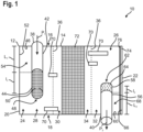
- Fig.1 shows schematically a cross-sectional view of a first embodiment of a silencer 10 according to the invention.
- the silencer 10 is part of an exhaust system of a vehicle (not shown), so that the silencer 10 is operated by a Exhaust gas flow generated by an internal combustion engine of the vehicle flows through it.
- the silencer 10 serves to dampen the noise emissions that arise from the combustion process taking place in the internal combustion engine or from the design of the entire exhaust system, in particular the pipe routing and the pipe lengths of pipes used in the exhaust system.
- the silencer 10 can also be used for other devices.
- the silencer 10 can be part of an exhaust system of a stationary engine (not shown), for example a stationary engine of a power generation device.
- the silencer 10 has a gas-tight silencer housing 12 which is formed by a casing 14 with a top side 16 and a bottom side 18 as well as a first end base 20 and a second end base 22.
- the silencer housing 12 shown has a substantially rectangular cross-section. However, it is understood that the silencer housing 12 can also be designed differently. Overall, the silencer housing 12 can be box-shaped or cylindrical, for example.
- Both the inlet chamber 24 and the outlet chamber 26 comprise several sub-chambers 28 and 30 or 32 and 34, which are each separated from each other by a partition wall 36.
- the inlet chamber 24 has an associated inlet pipe 38 which is designed to direct the exhaust gas flow of the exhaust system into the interior of the muffler housing 12, as indicated by the arrow P 1 in Fig.1 is indicated.
- the outlet chamber 26 has an associated outlet pipe 40 which is designed to discharge the exhaust gas flow from the interior of the muffler housing 12, as indicated by the arrow P 2 in Fig.1 indicated , for example in downstream components of the vehicle's exhaust system.
- the inlet pipe 38 comprises a first pipe section 42 and a second pipe section 44 along its axial extension direction, wherein the first pipe section 42 extends from an inner wall 46, which is associated with the top 16 of the silencer housing 12, to the second pipe section 44.
- the second pipe section 44 in turn runs from the connection point to the first pipe section 42 to an axial end 48 of the inlet pipe 38.
- the first pipe section 42 of the inlet pipe 38 has a length L 1 in the axial direction of the inlet pipe 38 and the second pipe section 44 of the inlet pipe 38 has a length I 1 in the axial direction of the inlet pipe 38.
- the total length of the inlet pipe 38 is thus the sum of the lengths L 1 and I 1 .
- the total length refers only to the length of the inlet pipe 38 by which the inlet pipe 38 extends into the muffler housing 12. It is understood that the inlet pipe 38 can also extend further outward from the muffler housing 12.
- the inlet pipe 38 is solid, i.e. impermeable to the exhaust gas flow.
- the inlet pipe 38 has a large number of openings 50 on the circumference, so that the inlet pipe 38 is porous on the circumference.
- the porosity of the second pipe section 44 is also referred to as porosity x 1 and is determined via the ratio of the sum of the area of all openings 50 in the circumferential surface of the second pipe section 44 to the total area of the circumferential surface of the second pipe section 44.
- the exhaust gas flow can flow from the inlet pipe 38 into the inlet chamber 24, namely into the sub-chamber 28, both via the axial end 48 and via the openings 50.
- a ⁇ /4 resonator 54 is formed, wherein the frequency at which the ⁇ /4 resonator 54 has a damping maximum, which is determined by the length L 1 .
- the damping behavior of the silencer 10 can be specifically adjusted by selecting the inlet pipe 38 used.
- the outlet pipe 40 comprises a first pipe section 56 and a second pipe section 58 along its axial extension direction, wherein the first pipe section 56 extends from an inner wall 60, which is associated with the underside 18 of the muffler housing 12, to the second pipe section 58.
- the second pipe section 58 in turn runs from the connection point to the first pipe section 56 to an axial end 62 of the outlet pipe 40.
- the first pipe section 56 of the outlet pipe 40 has a length L 2 in the axial direction of the outlet pipe 40 and the second pipe section 58 of the outlet pipe 40 has a length I 2 in the axial direction of the outlet pipe 40.
- the total length of the outlet pipe 40 is thus the sum of the lengths L 2 and I 2 .
- the total length of the outlet pipe 40 only refers to the length of the outlet pipe 40 by which the outlet pipe 40 extends into the silencer housing 12. It is understood that the outlet pipe 40, analogous to the inlet pipe 38, can also extend further outwards from the silencer housing 12.
- the outlet pipe 40 is solid, i.e. impermeable to the exhaust gas flow.
- the outlet pipe 40 has a large number of openings 64 on the circumference, so that the outlet pipe 40 is porous on the circumference.
- the porosity of the second pipe section 58 is also referred to as porosity x 2 and is determined via the ratio of the sum of the area of all openings 64 in the circumferential surface of the second pipe section 58 to the total area of the circumferential surface of the second pipe section 58.
- the exhaust gas flow can flow from the outlet chamber 26, namely the sub-chamber 32, into the outlet pipe 40 both via the axial end 62 and via the openings 64.
- a ⁇ /4 resonator 68 is formed between the inner wall 60, an inner wall 66 associated with the second end plate 22 and the first tube section 56, wherein the frequency at which the ⁇ /4 resonator 68 has a damping maximum is determined by the length L 2 .
- the lengths L 1 and L 2 can be the same or different.
- the ratio L 1 /L 2 is preferably in a range from 1 to 2.
- the porosity x 1 is preferably three to six times the porosity x 2 . That is, the inlet pipe 38 preferably has a higher porosity than the outlet pipe 40, as in Fig.1 is shown schematically.
- the resonance behavior of sound waves in the inlet chamber 24 and the outlet chamber 26 can be influenced by the positioning of the partition walls 36 along the top side 14 and bottom side 16 as well as by their porosity.
- the partition walls 36 also have connecting pipes 70 which fluidically connect the respective sub-chambers 28 and 30 or 34 and 32.
- the flow and damping behavior of the silencer 10 can be further adapted to the intended application scenario by positioning the connecting pipes 70 relative to the inlet pipe 38 or the outlet pipe 40 and by the length of the connecting pipes 70.
- an exhaust aftertreatment element 72 is arranged downstream of the inlet chamber 24 and upstream of the outlet chamber 26 .
- the exhaust aftertreatment element 72 serves to at least partially remove one or more pollutants from the exhaust gas flow flowing through the silencer 10. Accordingly, the silencer 10 shown is a coupled silencer-exhaust gas aftertreatment device.
- the type of exhaust aftertreatment element 72 is not further restricted and only needs to be tailored to the intended location and the expected composition of the exhaust gas flow.
- the exhaust aftertreatment element 72 is or includes an active or passive SCR catalyst (SCR for "selective catalytic reduction"), a filter element and/or an oxidation catalyst.
- a sound-absorbing material 74 is also attached to the inner wall 66 of the outlet chamber 26, which is associated with the end floor 22 and is used in particular to dampen high-frequency components of the noise spectrum.
- the sound-absorbing material 74 is fixed to the inner wall 66 by means of a perforated holding element 76, in particular by means of a micro-perforated holding element 76.
- the (micro-)perforated holding element 76 is used without the sound-absorbing material 74 being present.
- the acoustic damping is achieved by friction in the (micro-)perforation and by the volume lying between the respective inner wall and the holding element 76, which is selected via the distance between the respective inner wall and the holding element 76.
- Fig.2 shows schematically a second embodiment of the silencer 10 according to the invention.
- the second embodiment corresponds essentially to the first embodiment, so that only differences are discussed below.
- the same reference numerals identify the same or functionally identical components and reference is made to the above explanations.
- the inlet pipe 38 extends completely through the muffler housing 12, so that the inlet pipe 38 extends from the inner wall 46 associated with the upper side 16 to the inner wall 60 associated with the lower side 18.
- the axial end 48 is completely closed by the inner wall 60, so that an exhaust gas flow flowing through the inlet pipe 38 can reach the inlet chamber 24 exclusively via the openings 50 in the second pipe section 44 of the inlet pipe 38.
- the inlet pipe 38 in the second embodiment is designed as a mixing pipe.
- at least one treatment chemical 78 is supplied to the exhaust gas flow, which mixes with the exhaust gas flow and is transported together with the exhaust gas flow into the inlet chamber 24 and from there to the exhaust gas aftertreatment element 72.
- the treatment chemical 78 is, for example, a urea solution, which is reacted with nitrogen oxides contained in the exhaust gas flow in the exhaust gas aftertreatment element 72.
- the partition walls 36 have a first partial region 80 and a second partial region 82, wherein the partition wall 36 is gas-impermeable in the first partial region 80 and porous in the second partial region 82 and thus can be flowed through by the exhaust gas flow.
- a further ⁇ /4 resonator 84 is formed, the resonance frequency of which depends on the length L 1 of the first pipe section 42, analogously to the ⁇ /4 resonator 54.
- a further ⁇ /4 resonator 84 is formed between the first tube section 56, the inner wall 60 and the first partial region 80 of the partition wall 36 arranged in the outlet chamber 26.
- the outlet pipe 40 has a tulip-shaped axial end 62 to further prevent additional flow noise from occurring.
- the sound-absorbing material 74 is also attached to the inner wall 66 in the second embodiment. However, the sound-absorbing material 74 does not completely cover the inner wall 66 as in the first embodiment, but only partially and exclusively in the region of the inner wall 66 which is at the level of the second partial region 82 of the partition wall 36 associated with the exit chamber 26.
- Fig.3 shows schematically a third embodiment of the silencer 10 according to the invention.
- the third embodiment essentially corresponds to the first and second embodiments, so that only differences are discussed below.
- the same reference numerals identify the same or functionally identical components and reference is made to the above explanations.
- the inlet pipe 38 is not led through the top side 16, but through the first end plate 20 into the inlet chamber 24 and extends parallel to the top side 16 and the bottom side 18 into them, i.e. in the direction of the outlet chamber 26.
- outlet pipe 40 is not led out of the outlet chamber 26 through the bottom side 18, but through the second end plate 22 and extends parallel to the top side 16 and the bottom side 18.
- the changed orientations of the inlet pipe 38 and the outlet pipe 40 compared to the first and second embodiments also change where the ⁇ /4 resonators are formed.
- the ⁇ /4 resonators 54 and 68 in the third embodiment are formed between the inner walls 46, 52 and 60 and the first pipe section 42 of the inlet pipe 38 and between the inner walls 46, 66 and 60 and the first pipe section 56 of the outlet pipe 40, respectively.
- the sound-absorbing material 74 is also attached to the inner walls 46 and 60 associated with the upper side 16 and the lower side 18.
- the outlet pipe 40 has a gas-impermeable cap element 86 at its axial end 62, which completely closes the axial end 62.
- the exhaust gas flow from the outlet chamber 26 can only enter the outlet pipe 40 via the openings 64 in the second pipe section 58.
- the inlet pipe 38 can also have such a cap element 86.
- the silencer 10 is characterized by the possibility of being optimally tuned to the relevant frequency ranges in the noise spectrum without any adjustments being necessary in terms of the required installation space. In addition, an optimal compromise can be found between the damping effect and the counter pressure that occurs.
Landscapes
- Engineering & Computer Science (AREA)
- Chemical & Material Sciences (AREA)
- Combustion & Propulsion (AREA)
- Mechanical Engineering (AREA)
- General Engineering & Computer Science (AREA)
- Health & Medical Sciences (AREA)
- Chemical Kinetics & Catalysis (AREA)
- Toxicology (AREA)
- Exhaust Silencers (AREA)
Applications Claiming Priority (1)
| Application Number | Priority Date | Filing Date | Title |
|---|---|---|---|
| DE102022131738.2A DE102022131738A1 (de) | 2022-11-30 | 2022-11-30 | Schalldämpfer für eine Abgasanlage |
Publications (1)
| Publication Number | Publication Date |
|---|---|
| EP4379196A1 true EP4379196A1 (fr) | 2024-06-05 |
Family
ID=88837267
Family Applications (1)
| Application Number | Title | Priority Date | Filing Date |
|---|---|---|---|
| EP23210339.0A Withdrawn EP4379196A1 (fr) | 2022-11-30 | 2023-11-16 | Silencieux pour un système d'échappement |
Country Status (4)
| Country | Link |
|---|---|
| US (1) | US20240175381A1 (fr) |
| EP (1) | EP4379196A1 (fr) |
| CN (1) | CN118110583A (fr) |
| DE (1) | DE102022131738A1 (fr) |
Citations (7)
| Publication number | Priority date | Publication date | Assignee | Title |
|---|---|---|---|---|
| US4360076A (en) * | 1976-03-24 | 1982-11-23 | Nihon Rajieeta Kabushiki Kaisha (Nihon Radiator Co., Ltd.) | Muffler |
| US6058702A (en) * | 1996-05-13 | 2000-05-09 | Scambia Industrial Developments Aktiengesellschaft | Exhaust system for a motor vehicle, and motor vehicle |
| JP2002089230A (ja) * | 2000-09-20 | 2002-03-27 | Daihatsu Motor Co Ltd | 排気消音器の流出パイプ |
| JP2006125297A (ja) * | 2004-10-28 | 2006-05-18 | Calsonic Kansei Corp | 車両用消音器の水抜き構造 |
| US7328574B2 (en) * | 2002-02-25 | 2008-02-12 | Renault V.L. | Exhaust line and motor vehicle equipped therewith |
| US20120305330A1 (en) * | 2010-02-01 | 2012-12-06 | Futaba Industrial Co., Ltd. | Muffler for Internal Combustion Engine |
| WO2021210020A1 (fr) * | 2020-04-15 | 2021-10-21 | Tvs Motor Company Limited | Unité de traitement de bruit pour véhicule automobile |
Family Cites Families (24)
| Publication number | Priority date | Publication date | Assignee | Title |
|---|---|---|---|---|
| US1909394A (en) | 1930-05-31 | 1933-05-16 | Bendix Aviat Corp | Muffler |
| US2265342A (en) | 1940-05-18 | 1941-12-09 | Maxim Silencer Co | Silencer |
| CH289805A (de) | 1951-12-15 | 1953-03-31 | Rey Josef | Auspufftopf für Verbrennungsmotoren. |
| US3679024A (en) * | 1970-09-11 | 1972-07-25 | Stemco Mfg Co Inc | Muffler |
| CA1014028A (en) * | 1974-01-24 | 1977-07-19 | Raymon E. Hunt | Muffler method and apparatus |
| US4361206A (en) * | 1980-09-02 | 1982-11-30 | Stemco, Inc. | Exhaust muffler including venturi tube |
| JPH0536980Y2 (fr) | 1986-04-02 | 1993-09-20 | ||
| JP2000230413A (ja) | 1999-02-09 | 2000-08-22 | Honda Motor Co Ltd | 内燃機関の消音装置 |
| KR100323070B1 (ko) * | 1999-10-20 | 2002-02-08 | 정주호 | 자동차의 소음기 |
| KR200183228Y1 (ko) * | 1999-12-23 | 2000-05-15 | 대우중공업주식회사 | 중장비의 소음기 |
| JP3943818B2 (ja) * | 2000-09-21 | 2007-07-11 | 本田技研工業株式会社 | エンジンの消音器 |
| JP4392592B2 (ja) | 2003-12-12 | 2010-01-06 | トヨタ自動車株式会社 | 排気消音装置 |
| KR100842409B1 (ko) * | 2006-12-29 | 2008-07-01 | (주)성곡나노텍 | 차체 외부에 설치되는 전차(戰車)용 보조 소음기 |
| WO2011080793A1 (fr) * | 2009-12-28 | 2011-07-07 | トヨタ自動車株式会社 | Dispositif d'échappement pour moteur à combustion interne |
| CN201865723U (zh) * | 2010-11-24 | 2011-06-15 | 郑州三维内燃机净化消声技术有限公司 | 汽车排气消声器 |
| CN202811025U (zh) * | 2012-09-21 | 2013-03-20 | 厦门厦工机械股份有限公司 | 消声器的改进结构 |
| CN204703985U (zh) * | 2015-06-12 | 2015-10-14 | 襄阳楚安科技实业有限公司 | 消声器 |
| US10196947B2 (en) * | 2016-02-02 | 2019-02-05 | Kohler Co. | Muffler |
| KR102383239B1 (ko) * | 2017-10-16 | 2022-04-05 | 현대자동차 주식회사 | 환원제의 분사량을 제어하는 배기 정화 시스템 |
| KR20200006743A (ko) * | 2018-07-11 | 2020-01-21 | 현대자동차주식회사 | 차량용 헬름홀츠 소음기 |
| CN110454257A (zh) * | 2018-08-17 | 2019-11-15 | 广州威能机电有限公司 | 多孔谐振静音式消声器及发电机组 |
| US11434794B2 (en) * | 2019-06-06 | 2022-09-06 | Caterpillar Inc. | Exhaust sound attenuation device |
| DE102019132097A1 (de) * | 2019-11-27 | 2021-05-27 | Eberspächer Exhaust Technology GmbH | Abgasschalldämpfer |
| KR102869234B1 (ko) * | 2020-05-13 | 2025-10-10 | 현대자동차주식회사 | 차량의 배기계 소음 저감 장치 |
-
2022
- 2022-11-30 DE DE102022131738.2A patent/DE102022131738A1/de active Pending
-
2023
- 2023-11-16 EP EP23210339.0A patent/EP4379196A1/fr not_active Withdrawn
- 2023-11-23 CN CN202311570443.XA patent/CN118110583A/zh active Pending
- 2023-11-29 US US18/522,358 patent/US20240175381A1/en active Pending
Patent Citations (7)
| Publication number | Priority date | Publication date | Assignee | Title |
|---|---|---|---|---|
| US4360076A (en) * | 1976-03-24 | 1982-11-23 | Nihon Rajieeta Kabushiki Kaisha (Nihon Radiator Co., Ltd.) | Muffler |
| US6058702A (en) * | 1996-05-13 | 2000-05-09 | Scambia Industrial Developments Aktiengesellschaft | Exhaust system for a motor vehicle, and motor vehicle |
| JP2002089230A (ja) * | 2000-09-20 | 2002-03-27 | Daihatsu Motor Co Ltd | 排気消音器の流出パイプ |
| US7328574B2 (en) * | 2002-02-25 | 2008-02-12 | Renault V.L. | Exhaust line and motor vehicle equipped therewith |
| JP2006125297A (ja) * | 2004-10-28 | 2006-05-18 | Calsonic Kansei Corp | 車両用消音器の水抜き構造 |
| US20120305330A1 (en) * | 2010-02-01 | 2012-12-06 | Futaba Industrial Co., Ltd. | Muffler for Internal Combustion Engine |
| WO2021210020A1 (fr) * | 2020-04-15 | 2021-10-21 | Tvs Motor Company Limited | Unité de traitement de bruit pour véhicule automobile |
Also Published As
| Publication number | Publication date |
|---|---|
| CN118110583A (zh) | 2024-05-31 |
| US20240175381A1 (en) | 2024-05-30 |
| DE102022131738A1 (de) | 2024-06-06 |
Similar Documents
| Publication | Publication Date | Title |
|---|---|---|
| DE10356000B4 (de) | Schalldämpfer mit integriertem Katalysator | |
| EP0888493B1 (fr) | Systeme de silencieux | |
| DE19720410B4 (de) | Schalldämpfer | |
| EP2233708B2 (fr) | Dispositif de traitement des gaz d'échappement | |
| DE102005002289B4 (de) | Abgasbehandlungssystem | |
| DE69704351T2 (de) | Schalldämpfer | |
| DE60302555T2 (de) | Abgasstrang einer brennkraftmaschine und kraftfahrzeug aufweisend ein solcher abgasstrang | |
| DE102008046222B4 (de) | Abgasnachbehandlungseinrichtung | |
| EP1352172A1 (fr) | Silencieux comportant une pluralite de chambres de resonance | |
| DE69728891T3 (de) | Schalldämpfer für strömende gase | |
| DE102015222088B4 (de) | Schalldämpfer für eine Abgasanlage | |
| DE102016109388A1 (de) | Schalldämpfer für eine Abgasanlage einer Brennkraftmaschine, insbesondere für Kraftfahrzeuge mit Hybridantrieb | |
| DE69612948T2 (de) | Reaktionskammer für die katalytische Reinigung von Verbrennungsgasen | |
| EP1260682A1 (fr) | Ligne d'échappement d'un moteur à combustion interne, plus particulièrement d'un moteur diesel d'un véhicule utilitaire tel qu'un poids lourd ou un bus, comportant un dispositif de traitement des gaz d'échappement et d'insonorisation intégré | |
| EP1475522A2 (fr) | Dispositif combiné de traitement/ d'amortissement de gaz d' échappement dans la ligne d'échappement d'un moteur à combustion interne | |
| EP3623593B1 (fr) | Silencieux pour une conduite de gaz d'échappement d'un véhicule automobile et véhicule automobile doté d'un silencieux | |
| EP0931913A1 (fr) | Silencieux d'échappement pour moteurs à combustion interne | |
| DE19626980A1 (de) | Schalldämpfer für Kraftfahrzeuge | |
| EP2314834A1 (fr) | Système d'échappement et répartiteur en forme Y | |
| EP3704360B1 (fr) | Installation de gaz d'échappement pour le post-traitement et l'atténuation des sons de gaz d'échappement, de manière compacte et efficace | |
| EP4379196A1 (fr) | Silencieux pour un système d'échappement | |
| EP1096116A2 (fr) | Procédé et dispositif combinant la réduction catalytique de NOx et l'amortissement de son de gaz d' échappement dans la ligne d'échappement d'un moteur à combustion interne | |
| DE1426198A1 (de) | Schalldaempfer | |
| EP1541823B1 (fr) | Silencieux d'échappement | |
| EP3734033B1 (fr) | Silencieux de gaz d'échappement pour une installation d'échappement d'un moteur à combustion interne |
Legal Events
| Date | Code | Title | Description |
|---|---|---|---|
| PUAI | Public reference made under article 153(3) epc to a published international application that has entered the european phase |
Free format text: ORIGINAL CODE: 0009012 |
|
| STAA | Information on the status of an ep patent application or granted ep patent |
Free format text: STATUS: THE APPLICATION HAS BEEN PUBLISHED |
|
| AK | Designated contracting states |
Kind code of ref document: A1 Designated state(s): AL AT BE BG CH CY CZ DE DK EE ES FI FR GB GR HR HU IE IS IT LI LT LU LV MC ME MK MT NL NO PL PT RO RS SE SI SK SM TR |
|
| STAA | Information on the status of an ep patent application or granted ep patent |
Free format text: STATUS: REQUEST FOR EXAMINATION WAS MADE |
|
| 17P | Request for examination filed |
Effective date: 20240628 |
|
| RBV | Designated contracting states (corrected) |
Designated state(s): AL AT BE BG CH CY CZ DE DK EE ES FI FR GB GR HR HU IE IS IT LI LT LU LV MC ME MK MT NL NO PL PT RO RS SE SI SK SM TR |
|
| STAA | Information on the status of an ep patent application or granted ep patent |
Free format text: STATUS: EXAMINATION IS IN PROGRESS |
|
| 17Q | First examination report despatched |
Effective date: 20241022 |
|
| STAA | Information on the status of an ep patent application or granted ep patent |
Free format text: STATUS: THE APPLICATION IS DEEMED TO BE WITHDRAWN |
|
| 18D | Application deemed to be withdrawn |
Effective date: 20250423 |