EP4379261B1 - Verbrennungsdüse und brennkammer - Google Patents
Verbrennungsdüse und brennkammer Download PDFInfo
- Publication number
- EP4379261B1 EP4379261B1 EP23209242.9A EP23209242A EP4379261B1 EP 4379261 B1 EP4379261 B1 EP 4379261B1 EP 23209242 A EP23209242 A EP 23209242A EP 4379261 B1 EP4379261 B1 EP 4379261B1
- Authority
- EP
- European Patent Office
- Prior art keywords
- fuel
- air
- channel
- compressed air
- combustion
- Prior art date
- Legal status (The legal status is an assumption and is not a legal conclusion. Google has not performed a legal analysis and makes no representation as to the accuracy of the status listed.)
- Active
Links
Images




Classifications
-
- F—MECHANICAL ENGINEERING; LIGHTING; HEATING; WEAPONS; BLASTING
- F23—COMBUSTION APPARATUS; COMBUSTION PROCESSES
- F23R—GENERATING COMBUSTION PRODUCTS OF HIGH PRESSURE OR HIGH VELOCITY, e.g. GAS-TURBINE COMBUSTION CHAMBERS
- F23R3/00—Continuous combustion chambers using liquid or gaseous fuel
- F23R3/28—Continuous combustion chambers using liquid or gaseous fuel characterised by the fuel supply
- F23R3/38—Continuous combustion chambers using liquid or gaseous fuel characterised by the fuel supply comprising rotary fuel injection means
-
- F—MECHANICAL ENGINEERING; LIGHTING; HEATING; WEAPONS; BLASTING
- F23—COMBUSTION APPARATUS; COMBUSTION PROCESSES
- F23R—GENERATING COMBUSTION PRODUCTS OF HIGH PRESSURE OR HIGH VELOCITY, e.g. GAS-TURBINE COMBUSTION CHAMBERS
- F23R3/00—Continuous combustion chambers using liquid or gaseous fuel
- F23R3/02—Continuous combustion chambers using liquid or gaseous fuel characterised by the air-flow or gas-flow configuration
- F23R3/04—Air inlet arrangements
- F23R3/10—Air inlet arrangements for primary air
- F23R3/12—Air inlet arrangements for primary air inducing a vortex
- F23R3/14—Air inlet arrangements for primary air inducing a vortex by using swirl vanes
-
- F—MECHANICAL ENGINEERING; LIGHTING; HEATING; WEAPONS; BLASTING
- F23—COMBUSTION APPARATUS; COMBUSTION PROCESSES
- F23D—BURNERS
- F23D11/00—Burners using a direct spraying action of liquid droplets or vaporised liquid into the combustion space
- F23D11/36—Details
- F23D11/38—Nozzles; Cleaning devices therefor
- F23D11/383—Nozzles; Cleaning devices therefor with swirl means
-
- F—MECHANICAL ENGINEERING; LIGHTING; HEATING; WEAPONS; BLASTING
- F23—COMBUSTION APPARATUS; COMBUSTION PROCESSES
- F23R—GENERATING COMBUSTION PRODUCTS OF HIGH PRESSURE OR HIGH VELOCITY, e.g. GAS-TURBINE COMBUSTION CHAMBERS
- F23R3/00—Continuous combustion chambers using liquid or gaseous fuel
- F23R3/28—Continuous combustion chambers using liquid or gaseous fuel characterised by the fuel supply
- F23R3/286—Continuous combustion chambers using liquid or gaseous fuel characterised by the fuel supply having fuel-air premixing devices
-
- F—MECHANICAL ENGINEERING; LIGHTING; HEATING; WEAPONS; BLASTING
- F23—COMBUSTION APPARATUS; COMBUSTION PROCESSES
- F23R—GENERATING COMBUSTION PRODUCTS OF HIGH PRESSURE OR HIGH VELOCITY, e.g. GAS-TURBINE COMBUSTION CHAMBERS
- F23R2900/00—Special features of, or arrangements for continuous combustion chambers; Combustion processes therefor
- F23R2900/00002—Gas turbine combustors adapted for fuels having low heating value [LHV]
Definitions
- the invention relates to a combustor of a gas turbine engine (hereinafter referred to as "gas turbine”), and a nozzle (combustion nozzle) for discharging compressed air and fuel into a combustion chamber for combustion thereof in the combustor, and the combustor, and more specifically relates to a combustor that is suitable for a gas turbine capable of using hydrogen as fuel (hydrogen gas turbine) and a combustion nozzle thereof.
- gas turbine gas turbine engine
- nozzle combustion nozzle
- JP 2016-109309 A proposes a combustor for a gas turbine that uses hydrogen and methane as fuel.
- a combustion field is formed by injecting methane, which is the main fuel, from a premix fuel combustion main burner disposed on an upstream side of a combustion cylinder that makes up a combustion chamber.
- a plurality of diffusion combustion type reheating burners for injecting fuel from a peripheral wall into the combustion chamber is installed in the combustion field, and hydrogen is introduced from a part thereof.
- the main burner is a premix fuel combustion type burner, and accordingly the amount of nitrogen oxides (NOx) in high-temperature combustion gas generated in a primary combustion region on the upstream side of the combustion chamber is suppressed.
- the distributed layout of the reheating burners for introducing hydrogen enables fuel concentration in each combustion area of each reheating burner to be leaner, the combustion temperature of each reheating burner is suppressed overall, and the generation of NOx can be suppressed.
- adopting diffusion combustion type reheating burners reduces the risk of backfire.
- Japanese Unexamined Patent Application Publication No. 2020-106258 JP 2020-106258 A proposes a gas turbine that utilizes a highly reactive gas such as hydrogen as fuel.
- JP 2003-148734 A proposes gas turbine equipment. Fuel and air are delivered to the combustion chamber as a plurality of concentric jets, in order to reduce NOx emissions and to promote mixture of fuel and air, so as to improve flame stability in the combustion chamber.
- An air flow is formed on an outer circumferential side of a fuel flow within a premix fuel channel, around the fuel flow at the center.
- premixing enables fuel to be leaner, whereby low NOx can be advantageously realized.
- a large space is required to create a good mixture state, and as a tradeoff, the risk of backfire in which reverse flow of fuel occurs can increase.
- a configuration in which a plurality of nozzles is provided enables the fuel to be burned in a narrow space in a short time, and backfire to be suppressed.
- configurations of conventionally-known combustors for a gas turbines that can use hydrogen as fuel are intended for medium- or large-sized power generation engines and annular combustors that generate more than 1 megawatt (MW) of power, and application to small-sized engines or annular combustors such as those that generate around 1 MW of power is difficult.
- a micromix combustor e.g., JP 2020-106258 A
- a multi-cluster combustor which are known as conventional combustor configurations for gas turbines that can use hydrogen as fuel
- hydrogen is sprayed at a plurality of locations, and flames are distributed and laid out so as to be as small as possible.
- a combustion nozzle with a novel structure that is capable of mixing air and hydrogen sufficiently and uniformly in a small space before combustion, and achieving combustion in a rare fuel state, would be advantageous.
- the present disclosure provides a combustion nozzle with a novel structure that is suitable for combustors of small-sized gas turbines capable of using hydrogen as fuel.
- the present disclosure also provides a combustion nozzle that can be used in the combustors of small-sized gas turbines such as described above, with a novel structure that is capable of sufficiently mixing air and hydrogen uniformly in a small space before combustion while circumventing backfire, and achieving combustion in a rare fuel state.
- the present disclosure provides a gas turbine combustor provided with the combustion nozzle as described above.
- the combustion nozzle for discharging compressed air and fuel, to be combusted, into a combustion chamber of a combustor of a gas turbine.
- the combustion nozzle includes an air inlet configured to receive the compressed air, a nozzle orifice that opens into the combustion chamber and that is configured to discharge the compressed air, an air channel communicating between the air inlet and the nozzle orifice, a fuel channel for receiving the fuel, and one or more fuel outlets.
- the fuel channel is configured to discharge the fuel from the fuel outlets toward a flow of the compressed air discharged from the nozzle orifice.
- the air channel includes a Venturi section in which a channel cross-sectional area of the compressed air becomes relatively small. The fuel outlets are provided in the Venturi section.
- the "combustion nozzle” is a nozzle that mixes and discharges the compressed air and the fuel to be combusted into the combustion chamber in the combustor of the gas turbine, as described above.
- the "air channel” is a channel for passage of air that is defined between the “air inlet” for receiving the compressed air, and the “nozzle orifice” that opens into the combustion chamber.
- the “fuel channel” is a channel that receives fuel and performs passage thereof to the "fuel outlet”.
- the "Venturi section” is a section in which the "channel cross-sectional area” (cross-sectional area of a region through which fluid can flow) is narrowed to be relatively smaller than upstream and downstream of this section, in the air channel that communicates between the air inlet and the nozzle orifice.
- the fuel outlet which is an outlet of the fuel channel, opens into the Venturi section in the air channel, and is provided so as to discharge fuel toward the flow of compressed air flowing therethrough.
- the fuel may be hydrogen.
- the number of the fuel outlets may be determined in accordance with suitability. Furthermore, in order to more surely circumvent backfire from the combustion chamber to the fuel outlets, the fuel outlets may have an inner diameter (hole diameter) that is smaller than the quenching distance of the fuel. Specifically, when the fuel is hydrogen, the quenching distance is approximately 0.64 mm, and accordingly the diameter of the fuel outlets may be, for example, 0.6 mm or smaller.
- the Venturi section of the air channel may include a first region in which the channel cross-sectional area gradually decreases from an upstream side of the Venturi section along a direction of flow of the compressed air, and a second region in which the channel cross-sectional area gradually increases from a downstream end of the first region toward the nozzle orifice.
- the channel cross-sectional area of the flow of compressed air is smoothly and continuously constricted and then smoothly expanded. The flow of compressed air flows over the air channel while smoothly changing flow velocity, with almost no stagnation. Hardly any areas where the fuel concentration is locally high are generated, and the fuel is dispersed more uniformly. The combustion temperature is expected to become more uniformly distributed in the combustion field.
- a swirler may be provided on an upstream side of the Venturi section of the air channel, to change the flow of compressed air in accordance with an optional method into a swirling flow, in order to more uniformly disperse the fuel in the flow of compressed air.
- the flow of compressed air becomes the swirling flow and passes through the Venturi section at which the fuel is delivered, whereby the fuel is better dispersed in the air flow during the short travel distance of the air flow.
- a swirler may have a center cone disposed following a center axis along a direction of flow of the compressed air of the air channel, and a vane-like member extending in a radial direction from the center cone and having a surface inclined with respect to the center axis of the air channel.
- the flow of the compressed air flows along the surface of the vane-like member (which may have a shape like that of a screw propeller that does not rotate) to create the swirling flow.
- the swirler with such a configuration, when an outer diameter of the center cone through which air does not flow is too large with respect to an inner diameter of the air channel, the flow velocity on an extension line of the center cone will decrease, and the likelihood of reverse flow of flames from the combustion field to the center cone occurring will increase.
- a ratio of an outer diameter of the center cone of the swirler, as to an inner diameter of a portion at which the swirler is installed in the air channel may be below a predetermined value that is adjusted such that the flow velocity on the extension line of the center cone does not become excessively slow.
- the ratio of the outer diameter of the center cone of the swirler, as to the inner diameter of the portion at which the swirler is installed in the air channel may be sufficiently large to circumvent reverse flow of fluid from the combustion chamber into the air channel. According to this configuration, melting damage of a distal end of the center cone due to flames is suppressed.
- the combustion nozzle may include a center-cone-interior channel having a fluid outlet.
- the center-cone-interior channel passes through the center cone of the swirler along the center axis following the direction of flow of compressed air in the air channel.
- the fluid outlet opens at the distal end of the center cone on the downstream side of the flow of compressed air. The compressed air is passed through the center-cone-interior channel, and the compressed air is discharged from the fluid outlet toward the combustion chamber.
- the center cone may extend so that the distal end on the downstream side of the flow of compressed air is located in the section of the first region in which the channel cross-sectional area of the Venturi section of the air channel gradually decreases.
- the distal end on the downstream side of the flow of compressed air may extend to the second region in which the channel cross-sectional area of the Venturi section of the air channel gradually increases.
- the distal end of the center cone is disposed at a distance from the combustion field, whereby melting damage of the distal end of the center cone is circumvented.
- the flow velocity of the air flow around the distal end of the center cone increases, and reverse flow of the combustion fluid to the distal end of the center cone is circumvented.
- the combustion nozzle may include a center-cone-interior channel having a fluid outlet.
- the center-cone-interior channel passes through the center cone of the swirler along the center axis following the direction of flow of compressed air in the air channel.
- the fluid outlet opens at the distal end of the center cone on the downstream side of the flow of compressed air.
- the fuel is passed through the center-cone-interior channel and the fuel is discharged from the fluid outlet toward the combustion chamber. According to this configuration, the fuel is expected to be mixed better with the compressed air flow in the vicinity of the nozzle orifice.
- further flow paths for air may extend passing through the peripheral wall defining the air channel.
- Air outlets are provided on the inner-side surface of the peripheral wall in the second region of the Venturi section, or in the inner-side surface of the peripheral wall in the vicinity of the downstream end of the first region of the Venturi section.
- the flows of compressed air flowing through the peripheral-edge air flow paths are delivered from the air outlets to the flow of compressed air passing through the air channel.
- the air and the fuel are mixed better in the air-fuel mixture of the compressed air and the fuel sent to the combustion chamber. Uneven combustion density is suppressed from occurring. Further suppression in the amount of NOx generated is expected.
- the discharge direction of the fluid from the air outlets and the fuel outlets may be inclined in optional directions with respect to the radial direction from the center axis of the air channel. Thus, even better mixing of the air and the fuel is expected.
- a state in which compressed air and fuel are sufficiently mixed, and the fuel is rare in a combustion field, can be realized in a combustion chamber. Accordingly, as described above, the combustion temperature does not become excessively high, and the amount of NOx generated can be suppressed.
- Another aspect of the present disclosure is a combustor of a gas turbine, the combustor including a combustion nozzle for discharging compressed air and fuel, to be combusted, into a combustion chamber.
- the combustion nozzle includes an air inlet configured to receive the compressed air, a nozzle orifice that opens into the combustion chamber and that is configured to discharge the compressed air, an air channel communicating between the air inlet and the nozzle orifice, a fuel channel for receiving the fuel, and a fuel outlet.
- the fuel channel is configured to discharge the fuel from the fuel outlet toward a flow of the compressed air discharged from the nozzle orifice.
- the air channel includes a Venturi section in which a channel cross-sectional area of the compressed air becomes relatively small.
- the fuel outlet is provided in the Venturi section.
- the combustion nozzles may have various characteristic configurations as described above.
- the combustion nozzle of the combustor of the gas turbine described above is capable of achieving sufficiently uniform mixing of the fuel with the flow of compressed air and rarefication of fuel concentration over a relatively short distance, when delivering the flow of compressed air and fuel into the combustion chamber.
- This combustion nozzle can be used as a combustion nozzle for a combustor of a small-sized gas turbine in which backfire is circumvented and the amount of NOx generated is suppressed, even when a fuel such as hydrogen with a high combustion temperature is used.
- the combustion nozzle and the combustor equipped therewith can be used in gas turbines that use hydrogen as fuel, which are downsized so as to be installable in vehicles such as automobiles and so forth. Thus, hydrogen gas turbines are anticipated to come into more widespread use.
- a combustion nozzle according to an embodiment is advantageously used in a combustor of a gas turbine fueled by hydrogen or some other substance that is lighter in mass and has a higher combustion temperature than hydrocarbon-based materials that have been used heretofore.
- a combustion nozzle 2 is installed in an opening portion 3o in a housing 3h of a combustion chamber 3 that defines a combustion field 3f.
- compressed air PA enters from a compressor (omitted from illustration) that is linked to a turbine (omitted from illustration) through a compressed air supply ring 4 that is ring-like and that is defined on an outer circumference of the combustion chamber 3.
- fuel F flows in from a fuel tank (omitted from illustration), through a fuel supply line 2a. These are then mixed and delivered to the combustion field 3f for combustion thereof.
- a peripheral wall portion 2b that is substantially cylindrical and that extends at a middle portion thereof in an axial direction of the cylindrical shape, and defines an air channel 2x opening at a nozzle orifice 2d that fits into the opening portion 3o of the combustion chamber.
- the combustion nozzle 2 takes in compressed air PA from air inlets 4a formed on an upstream side of the peripheral wall portion 2b, and delivers this air to the combustion field 3f from the nozzle orifice 2d.
- the cross-section of the air channel 2x in a direction perpendicular to a flow direction of the fluid may be substantially circular, but is not limited to thereto.
- fuel channels 2 ⁇ through which the fuel F supplied over the fuel supply line 2a flows, are formed inside the peripheral wall portion 2b, passing through the peripheral wall portion 2b, and opening at fuel outlets 2f on an inner wall of the peripheral wall portion 2b. Fuel is injected toward the flow of compressed air PA flowing in the air channel 2x.
- the fuel outlets 2f are typically disposed at a plurality of portions at substantially equidistant intervals along a circumferential direction of the air channels 2x. Note that in the peripheral wall portion 2b, the fuel channels 2 ⁇ pass through portions where no air flow paths pass, so as not to interfere with the air flow paths from the air inlets 4a to the air channels 2x.
- a "Venturi section” 2e i.e., a section in which a cross-sectional area of the channel (the cross-sectional area in the direction perpendicular to the flow direction of the fluid in a region in which the fluid can flow) is reduced to be relatively smaller than upstream and downstream of this section, is formed in the air channel 2x as illustrated in FIG. 1C .
- the fuel outlets 2f are disposed in this Venturi section 2e.
- the fuel F is dispersed in the flow of compressed air PA in a state in which the flow velocity thereof is higher.
- This enables the fuel to be mixed more uniformly and thoroughly with the compressed air, in a shorter travel distance, than when the fuel is simply merged with the flow of compressed air. Occurrence of areas where the fuel concentration is locally high is suppressed.
- the flow of compressed air PA in which the fuel F is dispersed having passed through the Venturi section 2e, and flowing out from the nozzle orifice 2d to the combustion field 3f in the combustion chamber, spreads over a wide space. This reduces overall fuel concentration.
- the fuel outlets 2f are provided at locations where the flow velocity of the compressed air PA increases, to which the fuel F is delivered.
- the fuel is dispersed in the air at the nozzle orifice 2d in a more uniform and rarefied manner, while circumventing backfire. This enables the amount of NOx that is generated to be suppressed.
- a ratio of the channel cross-sectional area or an inner diameter ratio of the Venturi section 2e as to the regions upstream and downstream of the Venturi section 2e in the air channel 2x, and the length of the Venturi section 2e in the flow direction, may be determined such that the fuel is more uniformly dispersed in the flow of the compressed air PA.
- the inner diameter and the channel cross-sectional area of the Venturi section 2e gradually decrease along the flow direction of the fluid, from the upstream side of the Venturi section 2e (first region 2ei), and reach the smallest diameter portion. Thereafter, the inner diameter and the channel cross-sectional area gradually increase toward the nozzle orifice 2d (second region 2eii).
- the flow velocity of the flow of compressed air smoothly increases and decreases without stagnation.
- the fuel outlets 2f provided in the Venturi section 2e may be provided at locations at which the flow velocity of the compressed air flow is high. The positions at which the fuel outlets 2f are disposed may be determined such that the fuel is more uniformly distributed in the flow of compressed air PA.
- the fuel outlets 2f may be provided in the vicinity of the smallest diameter portion of the Venturi section 2e. Specifically, the vicinity of the smallest diameter portion of the Venturi section 2e is a section pt upstream and downstream from the smallest diameter portion in FIG. 2 .
- a length pt of this vicinity section may be a section satisfying pt/p ⁇ 60% with respect to a length p of the Venturi section 2e (length of section in which the inner diameter is smaller than Y).
- the hole diameter of the fuel outlet 2f is preferably set to be smaller than the quenching distance of the fuel, in order to suppress backfire in which reverse flow of the combusted fluid in the fuel channel occurs.
- the quenching distance thereof is 0.64 mm.
- the hole diameter of the fuel outlets may be smaller, such as 0.6 mm or smaller, for example.
- the fuel outlets may be provided at a plurality of portions substantially equidistantly along the circumferential direction of the flow of compressed air, so that the fuel is more uniformly dispersed in the air flow thereof.
- the outer diameter of the center cone of the swirler may be designed such that the boss ratio R1/R2 is not excessively great (e.g., 0.4 or less (0.16 or less in terms of cross-sectional area ratio)).
- a region 2et where the channel cross-sectional area of the Venturi section 2e is the smallest may have a certain level of length in the flow direction.
- the nozzle orifice 2d may be formed so as to open directly (without forming the second region 2eii where the channel cross-sectional area gradually increases) from the smallest diameter portion of the Venturi section 2e.
- the center cone 5c of the swirler may extend to the smallest diameter portion of the Venturi section 2e, to the extent that the degree of fuel dispersion in the mixed fluid discharged from the nozzle orifice 2d is not reduced. This increases the flow velocity in the Venturi section. Reverse flow of the fluid from the combustion field 3f to the nozzle orifice 2d can be made to occur less readily.
- the center cone 5c extends to the Venturi section 2e as illustrated in FIG. 5A .
- One of the fuel channels 2 ⁇ passes through the center cone 5c, and one fuel outlet 2f is formed at the distal end thereof. Air and fuel is mixed better, thereby reducing the amount of NOx generated.
- the fuel channel 2 ⁇ may be formed only in the center cone 5c (with no fuel channels 2 ⁇ formed in the peripheral wall portion 2b of the nozzle) and the fuel outlet 2f may open at the distal end thereof, as illustrated in FIG. 5B . In this case, formation of the fuel channel 2 ⁇ is facilitated.
- the fuel outlets 2f opened at the distal end of the center cone 5c may be opened along an outer circumference of the distal end thereof so as to radially inject the fuel in the vicinity of the distal end of the center cone 5c, as illustrated in FIG. 5C .
- the vane-like members 5w of the swirler 5 for rotating the direction of the flow of air may be provided at the air inlets 4a, as illustrated in FIG. 6 .
- the configuration in which the vane-like members 5w are provided at the air inlet 4a may also be applied to the configurations illustrated in FIGS. 4A to 5C .
- additional air channels may be formed as described below.
- a swirler 5 having the center cone 5c is provided in the air channel 2x, an air channel is formed through the center cone 5c in the axial direction thereof, and the compressed air flows out from a distal end (2g) of the center cone 5c.
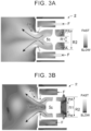
- the temperature of the center cone 5c becomes relatively high when no compressed air is discharged from the distal end of the center cone 5c, as illustrated in FIG. 7C .
- the temperature of the center cone 5c becomes relatively low, as illustrated in FIG. 7B .
- additional air channels (air channels inside the peripheral wall portion) 4b may be passed through the peripheral wall portion 2b that defines the air channel 2x, in parallel with the fuel passages 2 ⁇ .
- Air outlets 2g are provided arrayed along the circumferential direction with respect to the fuel outlets 2f. With respect to the flow of compressed air flowing through the air channel 2x, air flows are discharged from the air outlets 2g that are in the surroundings thereof. With such a configuration, the fuel F discharged from the fuel outlets 2f can be expected to be dispersed in the flow of compressed air more uniformly.
- the fuel outlets 2f and the air outlets 2g in the Venturi section 2e may be disposed alternating in the circumferential direction.
- the orientations thereof may be radially toward the center of the air channel 2x, as illustrated in FIG. 8B .
- the orientations thereof may be optionally inclined with respect to the radial directions towards the center of the air channel 2x, as illustrated in FIG. 8C . Accordingly, the fuel flows from the fuel outlets 2f collide with the air flows from the air outlets 2g in the flow of compressed air in the air channel 2x. The fuel and the air are mixed more uniformly.
- an air discharge ring 6 may be fitted to the outer circumference of the combustion nozzle 2, as illustrated in FIG. 9A , such that the compressed air PA flows out from air discharge holes 6a bored in the circumferential direction of the ring 6, as illustrated in FIG. 9B .
- the air and the fuel are mixed even more uniformly.
- the amount of NOx generated is suppressed.
- a cooling effect on the peripheral wall portion of the nozzle can also be obtained. Such an effect is particularly advantageous when the fuel is hydrogen, due to the high combustion temperature thereof.
- the air discharge ring 6 is simply a ring provided with through holes, and accordingly can be added at a relatively low cost.
- portions where the fuel and air are introduced are subdivided such that flames generated in the combustion field are minute flames, in order to suppress the combustion temperature to a low temperature. Accordingly, the nozzle occupies a large space, due to a large number of fuel supply ports and air supply ports being provided. It has been difficult to downsize the combustion nozzle or combustor.
- the fuel and air are sufficiently uniformly mixed while traveling over a relatively short distance. In the combustion field, areas where the fuel concentration is locally high are suppressed from occurring. Overall fuel concentration is also kept low. The fuel temperature does not become excessively high, locally or overall. Suppression of the amount of NOx generated is achieved.
Landscapes
- Engineering & Computer Science (AREA)
- Chemical & Material Sciences (AREA)
- Combustion & Propulsion (AREA)
- Mechanical Engineering (AREA)
- General Engineering & Computer Science (AREA)
- Gas Burners (AREA)
Claims (10)
- Verbrennungsdüse (2), die dazu ausgelegt ist, verdichtete Luft (PA) und zu verbrennenden Kraftstoff (F) in eine Verbrennungskammer (3) einer Brennkammer (1) einer Gasturbine abzugeben, wobei die Verbrennungsdüse (2) Folgendes umfasst:einen Lufteinlass (4a), der dazu ausgelegt ist, die verdichtete Luft (PA) aufzunehmen;eine Düsenöffnung (2d), die sich in die Verbrennungskammer (3) öffnet und die dazu ausgelegt ist, die verdichtete Luft (PA) abzugeben;einen Luftkanal (2x), der eine Verbindung zwischen dem Lufteinlass (4a) und der Düsenöffnung (2d) herstellt, wobei der Luftkanal (2x) einen Venturi-Abschnitt (2e) umfasst, in dem eine Querschnittsfläche des Luftkanals in Bezug auf den Luftkanal stromaufwärts und stromabwärts des Venturi-Abschnitts relativ klein wird;einen Kraftstoffkanal (2ϕ) zum Aufnehmen des Kraftstoffs (F);einen Verwirbler (5), der auf einer stromaufwärtigen Seite des Venturi-Abschnitts (2e) des Luftkanals (2x) bereitgestellt ist und der dazu ausgelegt ist, die Strömung der verdichteten Luft (PA) in eine Wirbelströmung zu ändern, wobei der Verwirbler Folgendes umfasst:einen Mittelkonus (5c), der so angeordnet ist, dass er entlang einer Strömungsrichtung der verdichteten Luft (PA) des Luftkanals (2x) einer Mittelachse folgt, undein flügelartiges Element (5w), das sich in einer radialen Richtung von dem Mittelkonus (5c) erstreckt und eine Oberfläche umfasst, die in Bezug auf die Mittelachse des Luftkanals (2x) geneigt ist, wobei die verdichtete Luft (PA) an der Oberfläche des flügelartigen Elements (5w) entlang strömt, um die Wirbelströmung zu erzeugen;wobei die Verbrennungsdüse ferner Folgendes umfasst:einen Mittelkonus-Innenkanal, der einen Fluidauslass (2g) umfasst, wobei der Mittelkonus-Innenkanal durch den Mittelkonus (5c) des Verwirblers (5) entlang der Mittelachse verläuft und sich der Fluidauslass (2g) an einem distalen Ende des Mittelkonus (5c) auf einer stromabwärtigen Seite der Strömung der verdichteten Luft (PA) öffnet, so dass die verdichtete Luft (PA) durch den Mittelkonus-Innenkanal verläuft und die verdichtete Luft (PA) aus dem Fluidauslass (2g) in Richtung der Brennkammer (3) abgegeben wird; undeinen oder mehrere Kraftstoffauslässe (2f), wobeider Kraftstoffkanal (2ϕ) dazu ausgelegt ist, den Kraftstoff (F) aus den Kraftstoffauslässen (2f) in Richtung einer Strömung der verdichteten Luft (PA) abzugeben, die aus der Düsenöffnung (2d) abgegeben wird, undwobei die Kraftstoffauslässe (2f) in dem Venturi-Abschnitt (2e) bereitgestellt sind.
- Verbrennungsdüse nach Anspruch 1, wobei die Kraftstoffauslässe (2f) im Wesentlichen äquidistant entlang einer Umfangsrichtung des Luftkanals (2x) angeordnet sind.
- Verbrennungsdüse nach Anspruch 1 oder 2, wobei der Venturi-Abschnitt (2e) Folgendes umfasst:einen ersten Bereich (2ei), in dem die Kanalquerschnittsfläche von einer stromaufwärtigen Seite des Venturi-Abschnitts (2e) entlang einer Strömungsrichtung der verdichteten Luft (PA) allmählich abnimmt, undeinen zweiten Bereich (2eii), in dem die Kanalquerschnittsfläche von einem stromabwärtigen Ende des ersten Bereichs (2ei) in Richtung der Düsenöffnung (2d) allmählich zunimmt.
- Verbrennungsdüse nach Anspruch 3, wobei:sich der Kraftstoffkanal (2ϕ) durch eine Umfangswand (2b) erstreckt, die den Luftkanal (2x) definiert; undsich die Kraftstoffauslässe (2f) auf einer innenseitigen Oberfläche der Umfangswand (2b) in dem zweiten Bereich (2eii) des Venturi-Abschnitts (2e) öffnen.
- Verbrennungsdüse nach Anspruch 3, wobei:sich der Kraftstoffkanal (2ϕ) durch eine Umfangswand (2b) erstreckt, die den Luftkanal (2x) definiert; undsich die Kraftstoffauslässe (2f) auf einer innenseitigen Oberfläche der Umfangswand (2b) in einer Nähe des stromabwärtigen Endes des ersten Bereichs (2ei) des Venturi-Abschnitts (2e) öffnen.
- Verbrennungsdüse nach Anspruch 1, wobei ein Verhältnis eines Außendurchmessers des Mittelkonus (5c) des Verwirblers (5) zu einem Innendurchmesser eines Abschnitts, an dem der Verwirbler (5) in dem Luftkanal (2x) installiert ist, unterhalb eines vorbestimmten Werts liegt.
- Verbrennungsdüse nach Anspruch 1, wobei:
der Venturi-Abschnitt (2e) Folgendes umfasst:einen ersten Bereich (2ei), in dem die Kanalquerschnittsfläche von der stromaufwärtigen Seite des Venturi-Abschnitts (2e) entlang der Strömungsrichtung der verdichteten Luft (PA) allmählich abnimmt, undeinen zweiten Bereich (2eii), in dem die Kanalquerschnittsfläche von einem stromabwärtigen Ende des ersten Bereichs (2ei) in Richtung der Düsenöffnung (2d) allmählich zunimmt; undsich der Mittelkonus (5c) des Verwirblers (5) derart erstreckt, dass sich ein distales Ende des Mittelkonus (5c) auf einer stromabwärtigen Seite der Strömung der verdichteten Luft (PA) zu einer Position auf dem stromabwärtigen Ende des ersten Bereichs (2ei) erstreckt. - Verbrennungsdüse nach Anspruch 1, wobei ein Innendurchmesser der Kraftstoffauslässe (2f) kleiner als ein Löschabstand des Kraftstoffs (F) ist.
- Verbrennungsdüse nach Anspruch 8, wobei der Kraftstoff (F) Wasserstoff ist.
- Brennkammer (1) einer Gasturbine, wobei die Brennkammer (1) die Verbrennungsdüse nach Anspruch 1 zum Abgeben von verdichteter Luft (PA) und zu verbrennendem Kraftstoff (F) in eine Verbrennungskammer (3) umfasst.
Applications Claiming Priority (1)
| Application Number | Priority Date | Filing Date | Title |
|---|---|---|---|
| JP2022193746A JP2024080498A (ja) | 2022-12-02 | 2022-12-02 | 水素ガスタービンに適した燃焼器及びその燃焼ノズル |
Publications (2)
| Publication Number | Publication Date |
|---|---|
| EP4379261A1 EP4379261A1 (de) | 2024-06-05 |
| EP4379261B1 true EP4379261B1 (de) | 2025-04-16 |
Family
ID=88778762
Family Applications (1)
| Application Number | Title | Priority Date | Filing Date |
|---|---|---|---|
| EP23209242.9A Active EP4379261B1 (de) | 2022-12-02 | 2023-11-10 | Verbrennungsdüse und brennkammer |
Country Status (4)
| Country | Link |
|---|---|
| US (1) | US12203656B2 (de) |
| EP (1) | EP4379261B1 (de) |
| JP (1) | JP2024080498A (de) |
| CN (1) | CN118129185A (de) |
Families Citing this family (5)
| Publication number | Priority date | Publication date | Assignee | Title |
|---|---|---|---|---|
| US11815269B2 (en) * | 2021-12-29 | 2023-11-14 | General Electric Company | Fuel-air mixing assembly in a turbine engine |
| WO2026027100A1 (en) * | 2024-08-02 | 2026-02-05 | Nuovo Pignone Tecnologie - S.R.L. | Fuel burner tube for a burner for highly reactive gas fuels |
| WO2026027101A1 (en) * | 2024-08-02 | 2026-02-05 | Nuovo Pignone Tecnologie - S.R.L. | Fuel burner tube for a burner for highly reactive gas fuels |
| CN119554662B (zh) * | 2025-01-03 | 2026-04-07 | 中国航发湖南动力机械研究所 | 氢燃料分级燃烧单元、全环燃烧室及航空发动机 |
| CN120083998B (zh) * | 2025-03-18 | 2025-12-16 | 成都中科翼能科技有限公司 | 一种燃气轮机及其燃烧室的双燃料喷嘴 |
Family Cites Families (29)
| Publication number | Priority date | Publication date | Assignee | Title |
|---|---|---|---|---|
| GB1307634A (en) * | 1970-07-23 | 1973-02-21 | Secr Defence | Fuel injection device for a gas turbine engine |
| US3912164A (en) * | 1971-01-11 | 1975-10-14 | Parker Hannifin Corp | Method of liquid fuel injection, and to air blast atomizers |
| JPS59108054U (ja) * | 1983-01-07 | 1984-07-20 | 株式会社東芝 | 燃料・空気予混合装置 |
| JPS6134325U (ja) * | 1984-07-31 | 1986-03-03 | 財団法人 電力中央研究所 | 接触燃焼器用予混合気形成器 |
| US4845952A (en) | 1987-10-23 | 1989-07-11 | General Electric Company | Multiple venturi tube gas fuel injector for catalytic combustor |
| JPH0792213B2 (ja) * | 1988-03-16 | 1995-10-09 | 高茂産業株式会社 | エゼクタ形バーナ装置 |
| DE4330083A1 (de) * | 1993-09-06 | 1995-03-09 | Abb Research Ltd | Verfahren zum Betrieb eines Vormischbrenners |
| JP2001280641A (ja) * | 2000-03-31 | 2001-10-10 | Mitsubishi Heavy Ind Ltd | ガスタービン燃焼器、および、ガスタービン燃焼器における燃料と空気の混合方法 |
| JP3960166B2 (ja) | 2001-08-29 | 2007-08-15 | 株式会社日立製作所 | ガスタービン燃焼器およびガスタービン燃焼器の運転方法 |
| WO2003072919A1 (en) | 2002-02-22 | 2003-09-04 | Catalytica Energy Systems, Inc. | Catalytically piloted combustion system and methods of operation |
| JP2003279043A (ja) * | 2002-03-22 | 2003-10-02 | Ishikawajima Harima Heavy Ind Co Ltd | ガスタービン用低NOx燃焼器 |
| US6862889B2 (en) * | 2002-12-03 | 2005-03-08 | General Electric Company | Method and apparatus to decrease combustor emissions |
| JP2005195284A (ja) * | 2004-01-08 | 2005-07-21 | Mitsubishi Heavy Ind Ltd | ガスタービン用燃料ノズル、ガスタービン用燃焼器、ガスタービン用燃焼器の燃焼方法 |
| US7059135B2 (en) | 2004-08-30 | 2006-06-13 | General Electric Company | Method to decrease combustor emissions |
| US7340900B2 (en) * | 2004-12-15 | 2008-03-11 | General Electric Company | Method and apparatus for decreasing combustor acoustics |
| GB0625016D0 (en) | 2006-12-15 | 2007-01-24 | Rolls Royce Plc | Fuel injector |
| US8215116B2 (en) | 2008-10-02 | 2012-07-10 | General Electric Company | System and method for air-fuel mixing in gas turbines |
| JP5581979B2 (ja) * | 2010-11-04 | 2014-09-03 | 株式会社Ihi | 燃焼加熱器 |
| US8925325B2 (en) * | 2011-03-18 | 2015-01-06 | Delavan Inc. | Recirculating product injection nozzle |
| JP6037338B2 (ja) * | 2011-06-02 | 2016-12-07 | 川崎重工業株式会社 | ガスタービン燃焼器 |
| CN104214799B (zh) * | 2014-09-03 | 2017-01-18 | 北京华清燃气轮机与煤气化联合循环工程技术有限公司 | 燃气轮机燃烧室轴向旋流喷嘴 |
| JP6440433B2 (ja) * | 2014-09-29 | 2018-12-19 | 川崎重工業株式会社 | 燃料噴射ノズル、燃料噴射モジュール、及びガスタービン |
| JP2016109309A (ja) | 2014-12-02 | 2016-06-20 | 川崎重工業株式会社 | ガスタービン用燃焼器、及びガスタービン |
| US10184665B2 (en) * | 2015-06-10 | 2019-01-22 | General Electric Company | Prefilming air blast (PAB) pilot having annular splitter surrounding a pilot fuel injector |
| JP7336848B2 (ja) | 2018-12-28 | 2023-09-01 | 川崎重工業株式会社 | 燃焼装置 |
| US20220373182A1 (en) * | 2021-05-21 | 2022-11-24 | General Electric Company | Pilot fuel nozzle assembly with vented venturi |
| CN215675303U (zh) * | 2021-07-30 | 2022-01-28 | 中国科学院工程热物理研究所 | 一种燃气轮机预混燃料喷嘴 |
| EP4614070A3 (de) * | 2021-12-21 | 2025-10-01 | General Electric Company | Gasturbinentriebwerk |
| CN115342384B (zh) * | 2022-07-06 | 2023-07-07 | 哈尔滨工程大学 | 一种燃气轮机燃烧室贫油预混一体化头部结构 |
-
2022
- 2022-12-02 JP JP2022193746A patent/JP2024080498A/ja active Pending
-
2023
- 2023-10-31 US US18/498,387 patent/US12203656B2/en active Active
- 2023-11-03 CN CN202311456272.8A patent/CN118129185A/zh active Pending
- 2023-11-10 EP EP23209242.9A patent/EP4379261B1/de active Active
Also Published As
| Publication number | Publication date |
|---|---|
| EP4379261A1 (de) | 2024-06-05 |
| JP2024080498A (ja) | 2024-06-13 |
| US20240183537A1 (en) | 2024-06-06 |
| US12203656B2 (en) | 2025-01-21 |
| CN118129185A (zh) | 2024-06-04 |
Similar Documents
| Publication | Publication Date | Title |
|---|---|---|
| EP4379261B1 (de) | Verbrennungsdüse und brennkammer | |
| EP3620719B1 (de) | Gasturbinenbrennkammer | |
| JP4162430B2 (ja) | ガスタービンエンジンの運転方法、燃焼器及びミキサ組立体 | |
| US5435126A (en) | Fuel nozzle for a turbine having dual capability for diffusion and premix combustion and methods of operation | |
| US6968692B2 (en) | Fuel premixing module for gas turbine engine combustor | |
| US5590529A (en) | Air fuel mixer for gas turbine combustor | |
| US6871501B2 (en) | Method and apparatus to decrease gas turbine engine combustor emissions | |
| US6363726B1 (en) | Mixer having multiple swirlers | |
| US5251447A (en) | Air fuel mixer for gas turbine combustor | |
| EP2530382B1 (de) | Brennstoffeinspritzdüse | |
| US9109553B2 (en) | Fuel injector | |
| US8117845B2 (en) | Systems to facilitate reducing flashback/flame holding in combustion systems | |
| JP4930921B2 (ja) | ガスタービンエンジンの燃焼室のための燃料インジェクタ | |
| US20170074521A1 (en) | Combustion device for gas turbine engine | |
| US20140182294A1 (en) | Gas turbine combustor | |
| CN109804200B (zh) | 旋流器、燃烧装置组件以及具有改善燃料/空气混合的燃气涡轮 | |
| EP1826485B1 (de) | Brenner und Verbrennungsverfahren dafür | |
| JP2015114098A (ja) | 予混合パイロットノズルを備える燃料噴射器 | |
| US20250198616A1 (en) | Nozzle assembly with a central fuel supply and at least one air channel | |
| US20240240792A1 (en) | Combustor and combustion nozzle thereof for hydrogen gas turbine | |
| EP3425281B1 (de) | Pilotdüse mit inline-vormischung | |
| CN116951471B (zh) | 燃气涡轮发动机及用于其的混合器组件、燃烧室、雾化燃料的方法 | |
| JP2025101930A (ja) | 水素ガスタービンに適した燃焼器及びその燃焼ノズル | |
| WO2025177639A1 (ja) | 2段燃焼ノズル、およびガスタービン燃焼器 |
Legal Events
| Date | Code | Title | Description |
|---|---|---|---|
| PUAI | Public reference made under article 153(3) epc to a published international application that has entered the european phase |
Free format text: ORIGINAL CODE: 0009012 |
|
| STAA | Information on the status of an ep patent application or granted ep patent |
Free format text: STATUS: REQUEST FOR EXAMINATION WAS MADE |
|
| 17P | Request for examination filed |
Effective date: 20231126 |
|
| AK | Designated contracting states |
Kind code of ref document: A1 Designated state(s): AL AT BE BG CH CY CZ DE DK EE ES FI FR GB GR HR HU IE IS IT LI LT LU LV MC ME MK MT NL NO PL PT RO RS SE SI SK SM TR |
|
| GRAP | Despatch of communication of intention to grant a patent |
Free format text: ORIGINAL CODE: EPIDOSNIGR1 |
|
| STAA | Information on the status of an ep patent application or granted ep patent |
Free format text: STATUS: GRANT OF PATENT IS INTENDED |
|
| INTG | Intention to grant announced |
Effective date: 20241125 |
|
| RIN1 | Information on inventor provided before grant (corrected) |
Inventor name: MINAMI, TAKAHIRO Inventor name: HIRANO, SHIGERU Inventor name: TATEBAYASHI, YASUSHI Inventor name: KASUGA, SHUNSUKE |
|
| GRAS | Grant fee paid |
Free format text: ORIGINAL CODE: EPIDOSNIGR3 |
|
| GRAA | (expected) grant |
Free format text: ORIGINAL CODE: 0009210 |
|
| STAA | Information on the status of an ep patent application or granted ep patent |
Free format text: STATUS: THE PATENT HAS BEEN GRANTED |
|
| AK | Designated contracting states |
Kind code of ref document: B1 Designated state(s): AL AT BE BG CH CY CZ DE DK EE ES FI FR GB GR HR HU IE IS IT LI LT LU LV MC ME MK MT NL NO PL PT RO RS SE SI SK SM TR |
|
| REG | Reference to a national code |
Ref country code: GB Ref legal event code: FG4D |
|
| REG | Reference to a national code |
Ref country code: CH Ref legal event code: EP Ref country code: DE Ref legal event code: R096 Ref document number: 602023002958 Country of ref document: DE |
|
| REG | Reference to a national code |
Ref country code: IE Ref legal event code: FG4D |
|
| REG | Reference to a national code |
Ref country code: NL Ref legal event code: MP Effective date: 20250416 |
|
| PG25 | Lapsed in a contracting state [announced via postgrant information from national office to epo] |
Ref country code: NL Free format text: LAPSE BECAUSE OF FAILURE TO SUBMIT A TRANSLATION OF THE DESCRIPTION OR TO PAY THE FEE WITHIN THE PRESCRIBED TIME-LIMIT Effective date: 20250416 |
|
| REG | Reference to a national code |
Ref country code: AT Ref legal event code: MK05 Ref document number: 1785906 Country of ref document: AT Kind code of ref document: T Effective date: 20250416 |
|
| REG | Reference to a national code |
Ref country code: DE Ref legal event code: R084 Ref document number: 602023002958 Country of ref document: DE |
|
| PG25 | Lapsed in a contracting state [announced via postgrant information from national office to epo] |
Ref country code: PT Free format text: LAPSE BECAUSE OF FAILURE TO SUBMIT A TRANSLATION OF THE DESCRIPTION OR TO PAY THE FEE WITHIN THE PRESCRIBED TIME-LIMIT Effective date: 20250818 Ref country code: FI Free format text: LAPSE BECAUSE OF FAILURE TO SUBMIT A TRANSLATION OF THE DESCRIPTION OR TO PAY THE FEE WITHIN THE PRESCRIBED TIME-LIMIT Effective date: 20250416 Ref country code: ES Free format text: LAPSE BECAUSE OF FAILURE TO SUBMIT A TRANSLATION OF THE DESCRIPTION OR TO PAY THE FEE WITHIN THE PRESCRIBED TIME-LIMIT Effective date: 20250416 |
|
| REG | Reference to a national code |
Ref country code: LT Ref legal event code: MG9D |
|
| PG25 | Lapsed in a contracting state [announced via postgrant information from national office to epo] |
Ref country code: NO Free format text: LAPSE BECAUSE OF FAILURE TO SUBMIT A TRANSLATION OF THE DESCRIPTION OR TO PAY THE FEE WITHIN THE PRESCRIBED TIME-LIMIT Effective date: 20250716 Ref country code: GR Free format text: LAPSE BECAUSE OF FAILURE TO SUBMIT A TRANSLATION OF THE DESCRIPTION OR TO PAY THE FEE WITHIN THE PRESCRIBED TIME-LIMIT Effective date: 20250717 |
|
| PG25 | Lapsed in a contracting state [announced via postgrant information from national office to epo] |
Ref country code: PL Free format text: LAPSE BECAUSE OF FAILURE TO SUBMIT A TRANSLATION OF THE DESCRIPTION OR TO PAY THE FEE WITHIN THE PRESCRIBED TIME-LIMIT Effective date: 20250416 |
|
| PG25 | Lapsed in a contracting state [announced via postgrant information from national office to epo] |
Ref country code: BG Free format text: LAPSE BECAUSE OF FAILURE TO SUBMIT A TRANSLATION OF THE DESCRIPTION OR TO PAY THE FEE WITHIN THE PRESCRIBED TIME-LIMIT Effective date: 20250416 |
|
| PG25 | Lapsed in a contracting state [announced via postgrant information from national office to epo] |
Ref country code: HR Free format text: LAPSE BECAUSE OF FAILURE TO SUBMIT A TRANSLATION OF THE DESCRIPTION OR TO PAY THE FEE WITHIN THE PRESCRIBED TIME-LIMIT Effective date: 20250416 |
|
| PG25 | Lapsed in a contracting state [announced via postgrant information from national office to epo] |
Ref country code: AT Free format text: LAPSE BECAUSE OF FAILURE TO SUBMIT A TRANSLATION OF THE DESCRIPTION OR TO PAY THE FEE WITHIN THE PRESCRIBED TIME-LIMIT Effective date: 20250416 |
|
| PGFP | Annual fee paid to national office [announced via postgrant information from national office to epo] |
Ref country code: FR Payment date: 20250930 Year of fee payment: 3 |
|
| PG25 | Lapsed in a contracting state [announced via postgrant information from national office to epo] |
Ref country code: RS Free format text: LAPSE BECAUSE OF FAILURE TO SUBMIT A TRANSLATION OF THE DESCRIPTION OR TO PAY THE FEE WITHIN THE PRESCRIBED TIME-LIMIT Effective date: 20250716 |
|
| PG25 | Lapsed in a contracting state [announced via postgrant information from national office to epo] |
Ref country code: IS Free format text: LAPSE BECAUSE OF FAILURE TO SUBMIT A TRANSLATION OF THE DESCRIPTION OR TO PAY THE FEE WITHIN THE PRESCRIBED TIME-LIMIT Effective date: 20250816 |
|
| PG25 | Lapsed in a contracting state [announced via postgrant information from national office to epo] |
Ref country code: LV Free format text: LAPSE BECAUSE OF FAILURE TO SUBMIT A TRANSLATION OF THE DESCRIPTION OR TO PAY THE FEE WITHIN THE PRESCRIBED TIME-LIMIT Effective date: 20250416 |
|
| PGFP | Annual fee paid to national office [announced via postgrant information from national office to epo] |
Ref country code: DE Payment date: 20250930 Year of fee payment: 3 |
|
| PG25 | Lapsed in a contracting state [announced via postgrant information from national office to epo] |
Ref country code: DK Free format text: LAPSE BECAUSE OF FAILURE TO SUBMIT A TRANSLATION OF THE DESCRIPTION OR TO PAY THE FEE WITHIN THE PRESCRIBED TIME-LIMIT Effective date: 20250416 Ref country code: SM Free format text: LAPSE BECAUSE OF FAILURE TO SUBMIT A TRANSLATION OF THE DESCRIPTION OR TO PAY THE FEE WITHIN THE PRESCRIBED TIME-LIMIT Effective date: 20250416 |
|
| REG | Reference to a national code |
Ref country code: DE Ref legal event code: R097 Ref document number: 602023002958 Country of ref document: DE |
|
| PG25 | Lapsed in a contracting state [announced via postgrant information from national office to epo] |
Ref country code: CZ Free format text: LAPSE BECAUSE OF FAILURE TO SUBMIT A TRANSLATION OF THE DESCRIPTION OR TO PAY THE FEE WITHIN THE PRESCRIBED TIME-LIMIT Effective date: 20250416 |
|
| PG25 | Lapsed in a contracting state [announced via postgrant information from national office to epo] |
Ref country code: EE Free format text: LAPSE BECAUSE OF FAILURE TO SUBMIT A TRANSLATION OF THE DESCRIPTION OR TO PAY THE FEE WITHIN THE PRESCRIBED TIME-LIMIT Effective date: 20250416 |
|
| PG25 | Lapsed in a contracting state [announced via postgrant information from national office to epo] |
Ref country code: SK Free format text: LAPSE BECAUSE OF FAILURE TO SUBMIT A TRANSLATION OF THE DESCRIPTION OR TO PAY THE FEE WITHIN THE PRESCRIBED TIME-LIMIT Effective date: 20250416 |
|
| PG25 | Lapsed in a contracting state [announced via postgrant information from national office to epo] |
Ref country code: IT Free format text: LAPSE BECAUSE OF FAILURE TO SUBMIT A TRANSLATION OF THE DESCRIPTION OR TO PAY THE FEE WITHIN THE PRESCRIBED TIME-LIMIT Effective date: 20250416 |
|
| PLBE | No opposition filed within time limit |
Free format text: ORIGINAL CODE: 0009261 |
|
| STAA | Information on the status of an ep patent application or granted ep patent |
Free format text: STATUS: NO OPPOSITION FILED WITHIN TIME LIMIT |
|
| REG | Reference to a national code |
Ref country code: CH Ref legal event code: L10 Free format text: ST27 STATUS EVENT CODE: U-0-0-L10-L00 (AS PROVIDED BY THE NATIONAL OFFICE) Effective date: 20260225 |
|
| PG25 | Lapsed in a contracting state [announced via postgrant information from national office to epo] |
Ref country code: RO Free format text: LAPSE BECAUSE OF FAILURE TO SUBMIT A TRANSLATION OF THE DESCRIPTION OR TO PAY THE FEE WITHIN THE PRESCRIBED TIME-LIMIT Effective date: 20250416 |
|
| 26N | No opposition filed |
Effective date: 20260119 |